GCv 4010 - Congélateur LIEBHERR - Notice d'utilisation et mode d'emploi gratuit
Retrouvez gratuitement la notice de l'appareil GCv 4010 LIEBHERR au format PDF.

| Type d'appareil | Réfrigérateur combiné ventilé |
| Capacité totale | Non précisé |
| Nombre de portes | 2 |
| Type de froid | Ventilé |
| Compartiment congélateur | Oui |
| Nombre d'étagères | 4 |
| Nombre de tiroirs congélateur | 2 |
| Type de commande | Non précisé |
| Matériau extérieur | Non précisé |
| Matériau intérieur | Non précisé |
| Type d'installation | Pose libre |
| Éclairage intérieur | Non précisé |
| Classe énergétique | Non précisé |
| Niveau sonore | Non précisé |
| Dimensions (HxLxP) | Non précisé |
| Poids | Non précisé |
| Fonction dégivrage | Automatique |
FOIRE AUX QUESTIONS - GCv 4010 LIEBHERR
Questions des utilisateurs sur GCv 4010 LIEBHERR
0 question sur cet appareil. Repondez a celles que vous connaissez ou posez la votre.
Poser une nouvelle question sur cet appareil
Téléchargez la notice de votre Congélateur au format PDF gratuitement ! Retrouvez votre notice GCv 4010 - LIEBHERR et reprennez votre appareil électronique en main. Sur cette page sont publiés tous les documents nécessaires à l'utilisation de votre appareil GCv 4010 de la marque LIEBHERR.
MODE D'EMPLOI GCv 4010 LIEBHERR
Appliance Documentation
GCv 40.. from index 21A
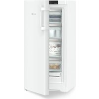
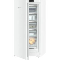
Gastro fridge/freezer combination ventilated
natural_image
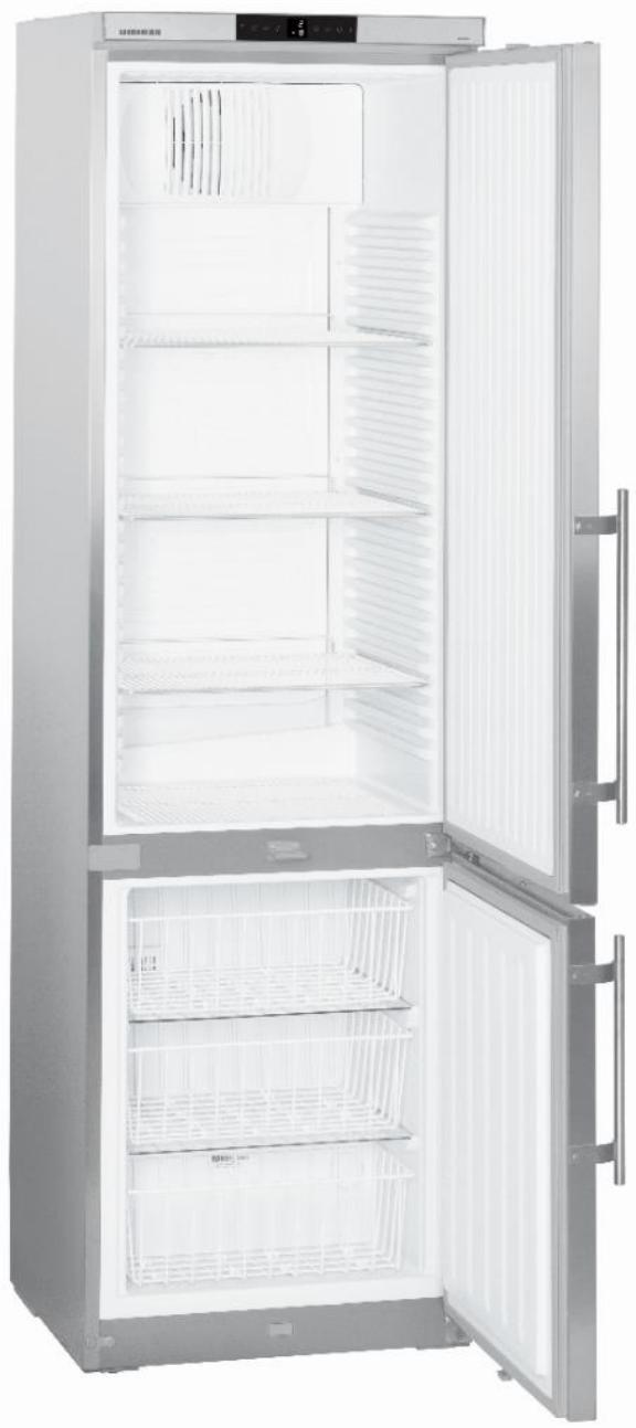
Interior view of a stainless steel refrigerator with open doors and side shelves (no visible text or symbols)Legal Notice
© 24.01.2017 Liebherr-Hausgeräte Lienz GmbH. All rights reserved.
No part of this documentation may be reproduced or processed, duplicated or distributed by means of electronic systems in any form whatsoever (print, photocopy or any other process) for purposes other than personal use without the written consent of Liebherr-Hausgeräte Lienz GmbH.
Liebherr-Hausgeräte Lienz GmbH reserves the right to change or amend the documentation at any time without prior notice. Liebherr-Hausgeräte Lienz GmbH assumes no liability for printing errors and ensuing damages.
Other brand or product names contained in this document are the brands of the respective holders of the rights and are hereby recognised as such.
Liebherr-Hausgeräte Lienz GmbH, Dr.-Hans-Liebherrstraße 1, 9900 Lienz, Austria, Phone +43 50809 20, E-Mail: info.lwl@liebherr.com, Internet: home.liebherr.com
Contents
1.0 Operating and control elements.... 4
1.1 Operating elements....4
1.2 Control elements....4
2.0 Functions at a glance....5
3.0 Description of Appliance 6
3.1 Sensor position, schematic diagram....6
4.0 Main components and their functions .... 7
4.1 Electrical components and functions 7
4.1.1 Refrigerator compartment....7
4.1.2 Freezer compartment....9
4.2 Refrigeration components and functions 10
4.2.1 Refrigerator compartment....10
4.2.2 Freezer compartment....10
4.2.3 Principle of operation of the refrigerating system 11
5.0 Assembly instructions / Parts replacement.... 12
5.1. General 12
5.1.1. Electronics....12
5.2 Refrigerator compartment 13
5.2.1 Air sensor 13
5.2.2 Evaporator sensor....13
5.2.3 Fan 14
5.2.4 Relay 15
5.3 Freezer compartment.... 16
5.3.1 Air sensor 16
5.3.2 Reed contact....16
5.4 Door closing mechanism.... 17
6.0 Technical Data....18
7.0 Service menu 19
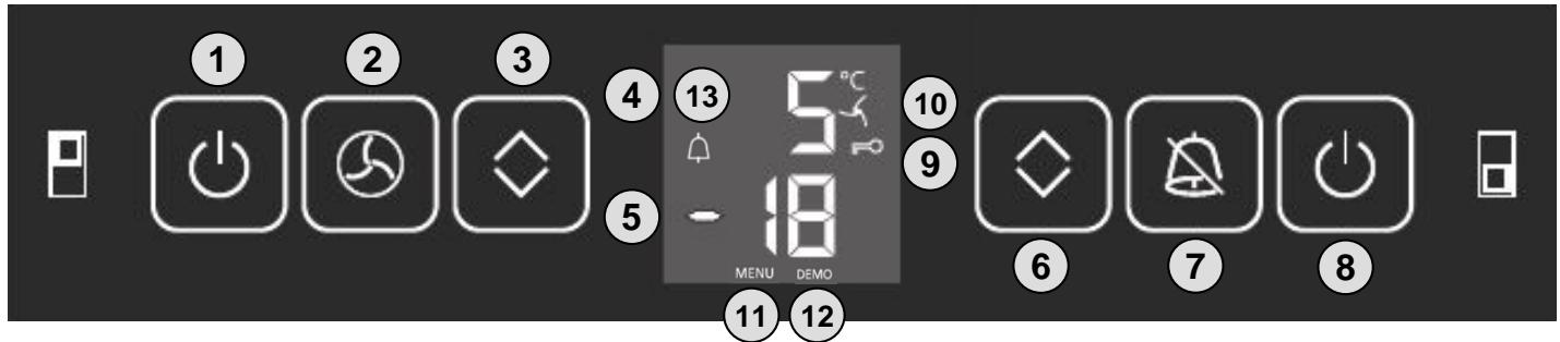
1.0 Operating and control elements
text_image
① ② ③ ④ ⑤ ⑥ ⑦ ⑧ ⑩ ⑪ MENU DEMO 5°C -181.1 Operating elements
1 ON/OFF button for refrigerator compartment
2 Ventilation button
3 Setting buttons temperature refrigerator compartment warmer / colder
4 Refrigerator compartment temperature display
5 Freezer compartment temperature display
6 Setting buttons temperature freezer compartment warmer / colder
7 OFF button for audible alarm
8 Freezer compartment ON/OFF button
1.2 Control elements
9 Key lock active
10 Ventilation activated
11 Menu active
12 Demo mode active
13 Alarm
2.0 Functions at a glance
| Control: | Electronics in conjunction with relay for the refrigerator compartment | |
| Temperature display: | Refrigerator compartment: Freezer compartment: | Actual value Actual value |
| Temperature range: | Refrigerator compartment: Freezer compartment: | +1 °C to +15 °C -14 °C to -28 °C |
| Temperature alarm: | Refrigerator compartment: Freezer compartment: | not featured visual and audible |
| Door alarm: | Refrigerator compartment: Freezer compartment: | Audible Audible |
| Volt-free contact: | Not featured | |
| Min/Max function: | Not featured | |
| Interface (RS 485): | Not featured | |
| Temperature monitor: | Not featured | |
| Fan: | Refrigerator compartment: Freezer compartment: | Featured Not featured |
| Defrosting: | Refrigerator compartment: Freezer compartment: | Automatic Manual |
| Interior light: | Refrigerator compartment: Freezer compartment: | Not featured Not featured |
| Service menu: | Featured | |
| Compressor: | Refrigerator compartment: Freezer compartment: | Standard Standard |
| Solenoid valve refrigeration circuit: | Not featured | |
3.0 Description of Appliance
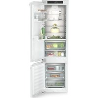
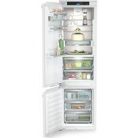
The GCv 40.. model is a gastro refrigerator/freezer combination
The refrigerator compartment is fitted with a freely suspended rear wall evaporator and a fan. Defrosting is automatic.
In the freezer compartment, the evaporator is foamed-in (wound around the inner liner). The freezer compartment must be defrosted manually.
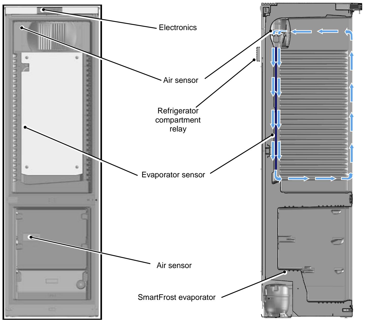
3.1 Sensor position, schematic diagram
text_image
Electronics Air sensor Refrigerator compartment relay Evaporator sensor Air sensor SmartFrost evaporator■ 3.1.1
4.0 Main components and their functions
4.1 Electrical components and functions
4.1.1 Refrigerator compartment
| Electronics | |
| Type: | Series 6 electronic control system |
| Components: | Integral PCB in conjunction with relay control for the refrigerator compartment |
| Setting range: | +1 °C to +15 °C |
| Display range: | 0 °C to +50 °C |
| Functions | |
| Door alarm: | When: Door open for longer than 3 minutes. |
| Audible: 3 beeps | |
| Defrosting: | The evaporator defrosts during the respective cooling pauses (no electrical heater). The refrigeration switches back on where required (evaporator sensor switch-on value). |
| Ventilation: | Ventilation ON: Fan in continuous operation |
| Ventilation OFF: Fan parallel to compressor | |
| Note: - The fan is generally switched off when the door is open- Upon start-up, the fan only runs if the evaporator is colder than +8°C. | |
| Child lock: | Activation is via the customer menu (see operating instructions).The ON/OFF button and the temperature adjustment buttons are inactive when the child lock is activated. The remaining functions can be used. |
| Sensors | |
| Air sensor: | Position: On the inner liner behind the fan cover |
| Function: - Switches the compressor OFF.- Generates the display value. | |
| Evaporator sensor: | Position: On the back of the evaporator |
| Function: - Switches the compressor ON.- Ends the defrost phase. | |
| Switches | |||
| Door switch: | Position: | On the underside of the front housing. | |
| Type: | Reed contact | ||
| Contact type: | Make contact switch | ||
| Function: | Activation via magnet on the door, magnet is replaceable. | ||
| Switching signal when: | |||
| Door closed: | Fan ON | ||
| Door open: | Fan OFF Door alarm ON | ||
| Relay: | Position: | mounted on the rear wall above condenser. | |
| Function: | absorbs the start-up current of the refrigerator compartment compressor. | ||
| Consumers / loads | |||
| Fan: | Position: | Rear centre in the fan cover. | |
| Function: | Runs permanently from start-up and only switches off with the door open. | ||
| Upon start-up, the fan only starts if the evaporator is colder than +8 °C. | |||
| Compressor: | Type: | Standard | |
| Upon start-up, the compressor will start with a 10 second delay. | |||
| Function: | ON: Evaporator sensor switch-on value. Note: Switch-on delay time (8 minutes) must have elapsed. | ||
| OFF: Air sensor switch-off value | |||
4.1.2 Freezer compartment
| Electronics | |||
| Type: | Series 6 electronic control system | ||
| Components: | Integral PCB | ||
| Setting range: | -28 °C to -14 °C | ||
| Display range: | -28 °C to -1 °C | ||
| Functions | |||
| Temperature alarm: | When: target value: -14 °C to -24 °CAlarm value: 4K warmer than target value.Target value: -25 °C to -28 °CAlarm value: -20 °CAudible: 4 beeps (suppressed upon start-up)Visual: Flashing temperature display and bell symbol.For temperatures above zero “- -” and bell symbolOn start-up, the temperature display flashes until the switch-off value is reached, the audible alarm is suppressed”. | ||
| Door alarm: | When: Door open for longer than 3 minutes.Audible: 3 beeps | ||
| Defrosting: | The freezer compartment must be defrosted manually. | ||
| Child lock: | Activation is via the customer menu (see operating instructions).The ON/OFF button and the temperature adjustment buttons are inactive when the child lock is activated. The remaining functions are available for unrestricted use. | ||
| Sensors | |||
| Air sensor: | Position: On the rear wall of the inner liner, behind the top drawer.Function: - Switches the compressor ON and OFF.- Generates the display value.- Activates the temperature alarm. | ||
| Switches | |||
| Door switch: | Position: In the cross connector of the appliance base.Type: Reed contactContact type: Make contact switchFunction: Activation via magnet on the bottom of the door, magnet is replaceable.Switching signal when:Door closed: Door alarm OFFDoor open: Door alarm ON | ||
| Consumers / loads | |||
| Compressor: | Type: StandardFunction: ON: Air sensor switch-on value.Note: Switch-on delay time (8 minutes) must have elapsed.OFF: Air sensor switch-off value | ||
4.2 Refrigeration components and functions
4.2.1 Refrigerator compartment
| Compressor | |
| Type of appliance: | Standard |
| Evaporator | |
| Type of appliance: | Rear wall evaporator |
| Type of installation: | Suspended freely |
| Injection point: | Top |
| Flow sequence: | From top to bottom |
4.2.2 Freezer compartment
| Compressor | |
| Type of appliance: | Standard |
| Evaporator | |
| Type of appliance: | Evaporator tube |
| Type of installation: | Foamed-in |
| Injection point: | Top |
| Flow sequence: | From top to bottom |
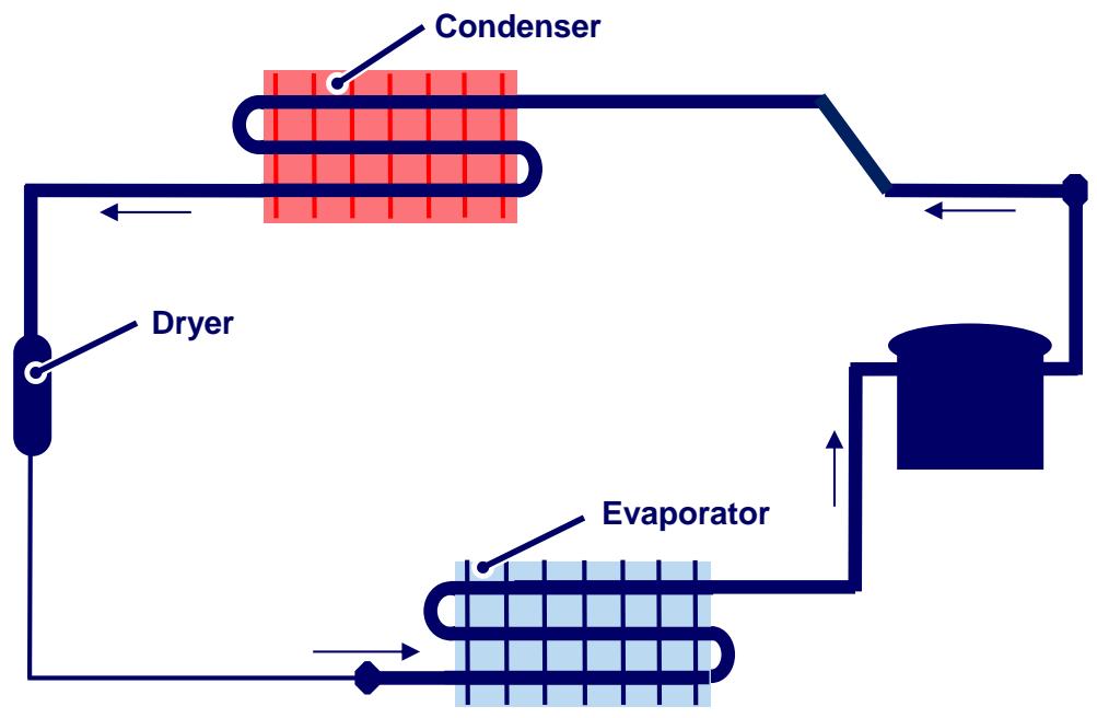
4.2.3 Principle of operation of the refrigerating system
4.2.3.1 Refrigerating

flowchart
graph TD
    A["Condenser"] --> B["Dryer"]
    B --> C["Evaporator"]
    C --> D["Recycle"]
    D --> A
4.2.3.2 Freezing
flowchart
graph TD
    A["Condenser"] --> B["Dryer"]
    B --> C["Evaporator"]
    C --> D["Refrigerator"]
    D --> A
5.0 Assembly instructions / Parts replacement
5.1. General
5.1.1. Electronics
Front housing:
- Unclip the covers on the underside of the front housing and remove both screws.
- Pull front housing forward slightly and flip up.
- Disconnect cable.
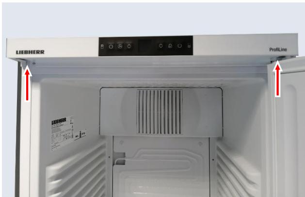
text_image
LIEBHERR ProfitLineFig. 5.1.1/1
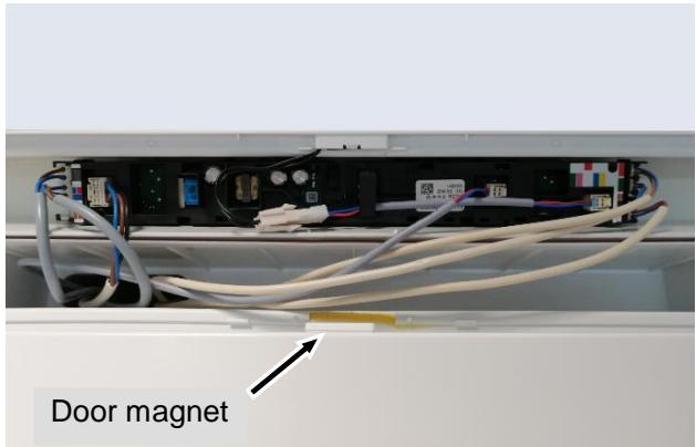
text_image
Door magnetFig. 5.1.1/2
Integral PCB carrier:
- Unlock the retaining lugs and pull out the PCB carriers belonging to the integral PCBs.
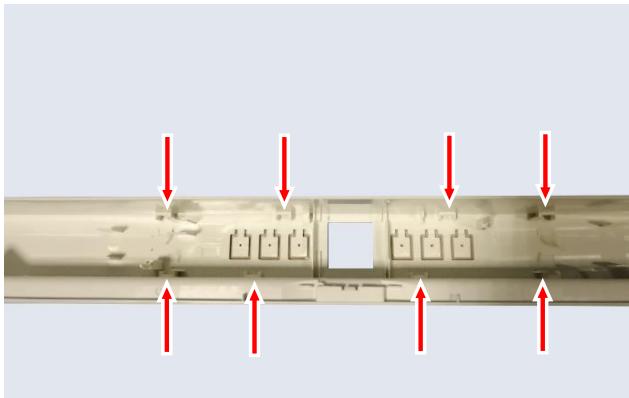
natural_image
Close-up of a mechanical component with red arrows pointing to internal features (no text or symbols visible)Fig. 5.1.1/3
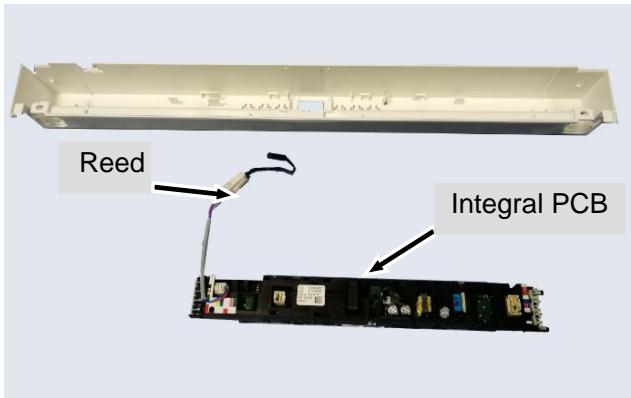
text_image
Reed Integral PCBFig. 5.1.1/4
5.2 Refrigerator compartment
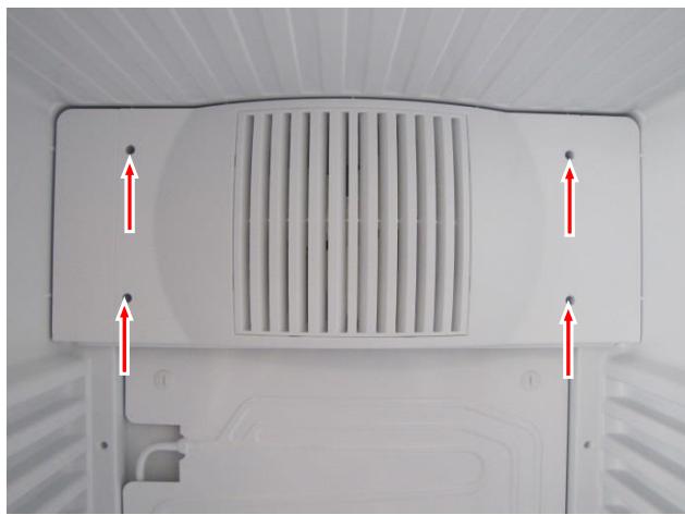
5.2.1 Air sensor
Fan cover:
- Remove stoppers and screws and tilt the fan cover forwards.
- Remove the sensor from the holder
- Pull the sensor outwards via the rear wall.
natural_image
Top-down view of a white air vent with ventilation grilles and red arrows indicating airflow direction (no text or symbols)Fig. 5.2.1/1
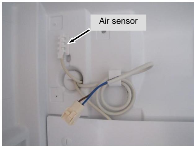
text_image
Air sensorFig. 5.2.1/2
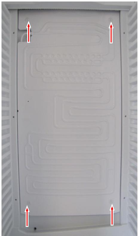
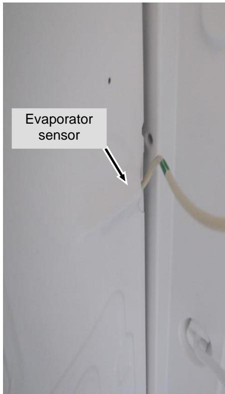
5.2.2 Evaporator sensor
Disassembly:
- Undo bayonet screw.
- Swivel the evaporator carefully to the left.
- Remove sensor from the holder and pull outwards via the rear wall.
natural_image
Interior view of a white electronic device casing with patterned circuit lines and red directional arrows indicating orientation (no text or symbols)Fig. 5.2.2/1
text_image
Evaporator sensorFig. 5.2.2/2
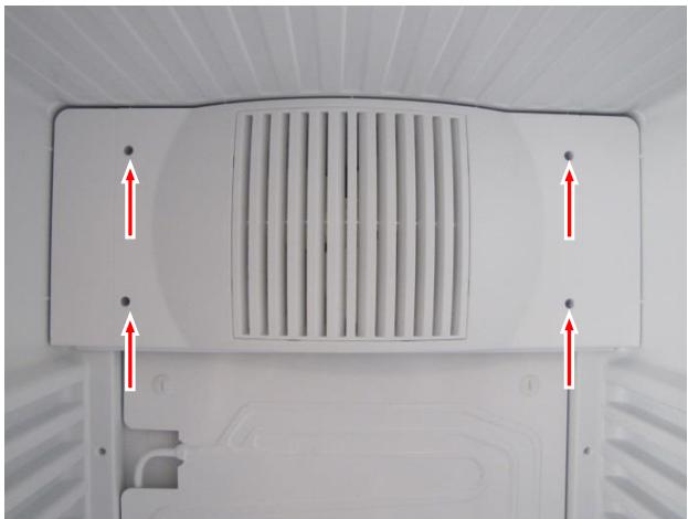
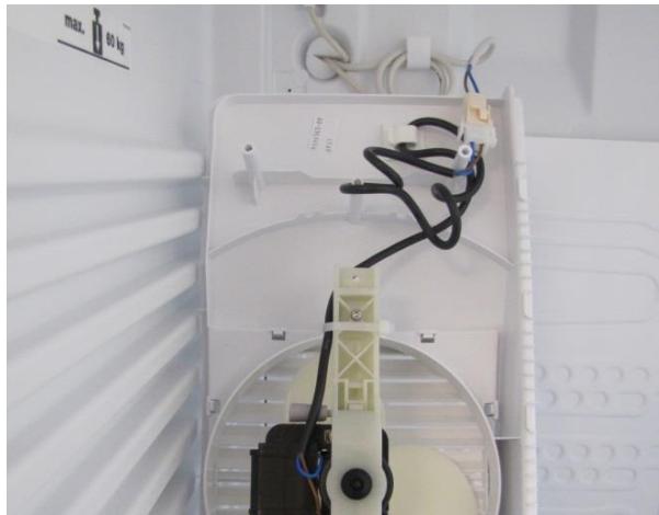
5.2.3 Fan
Fan cover:
- Undo the fan cover and tilt forwards.
- Disconnect cable and remove fan complete with cover.
natural_image
Top-down view of a white air vent or fan structure with ventilation grilles and red arrows pointing to specific points (no text or symbols visible)Fig. 5.2.3/1
natural_image
Interior view of an open air conditioner unit with visible wiring and a mounted device (no text or symbols)Fig. 5.2.3/2
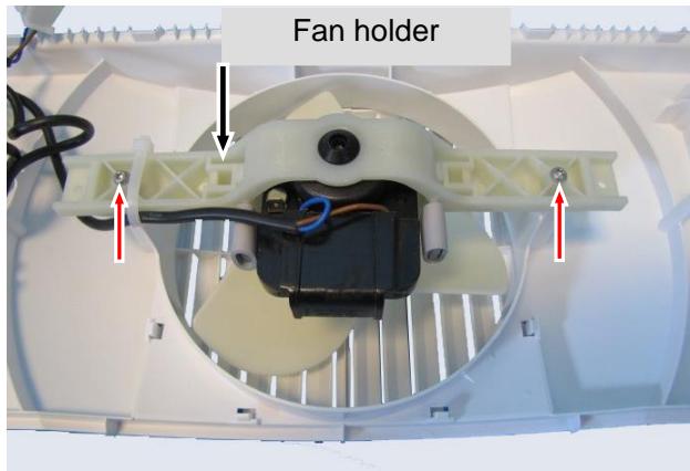
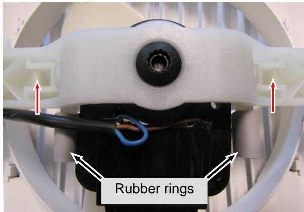
Fan:
- Unscrew fan mount from cover.
- Strip the rubber rings and undo the holder (unclip 2 lugs).
text_image
Fan holderFig. 5.2.3/3
text_image
Rubber ringsFig. 5.2.3/4
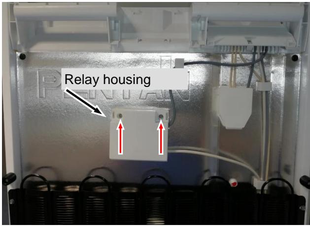
5.2.4 Relay
Relay:
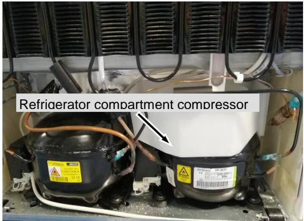
- Mounted on the back of the appliance above the condenser.
- Undo marked screws.
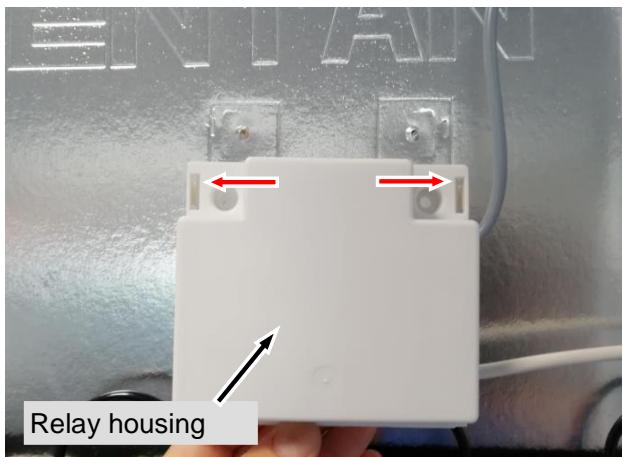
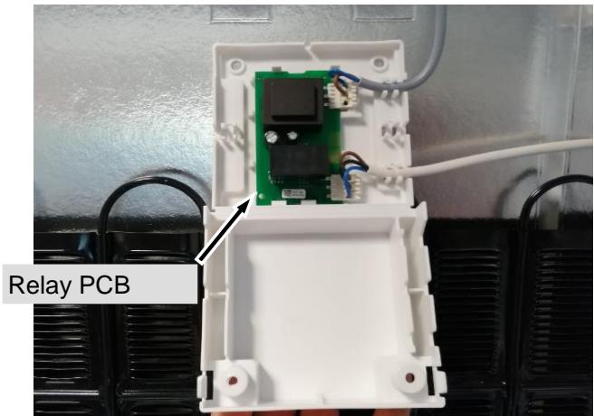
- Press apart locking catches with a flat screwdriver on both sides and open relay housing.
Note: In combination with the integral PCB controls the compressor for the refrigerator compartment and compensates the start-up current on the integral PCB.
text_image
Relay housingFig. 5.2.4/1
text_image
RELAY Relay housingFig. 5.2.4/2
text_image
Relay PCBFig. 5.2.4/3
text_image
Refrigerator compartment compressorFig. 5.2.4/ 4
5.3 Freezer compartment
5.3.1 Air sensor
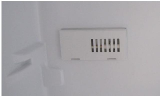
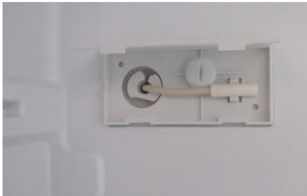
Sensor holder:
- Unclip the holder lid.
- Remove sensor from the holder and pull outwards via the rear wall.
natural_image
Close-up of a white electrical outlet or fixture mounted on a wall, with no visible text or symbols.Fig. 5.3.1/1
natural_image
Close-up of a white plastic electrical outlet with a circular component and a cylindrical tube, mounted on a wall (no text or symbols visible)Fig. 5.3.1/2
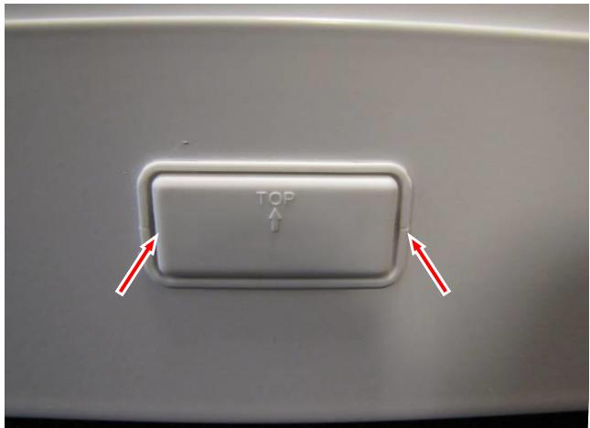
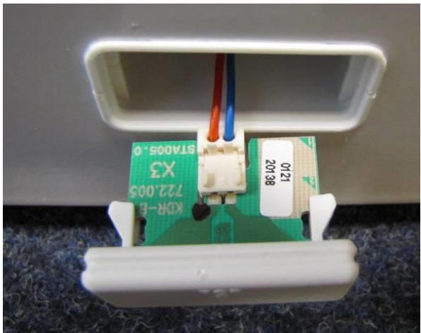
5.3.2 Reed contact
Holder: - Unclip cover on left and right. - Disconnect cable.
text_image
TOP ↑Fig. 5.3.2/1
natural_image
Close-up of a small electronic device with green circuit board and wiring, mounted on a white base (no visible text or symbols)Fig. 5.3.2/2
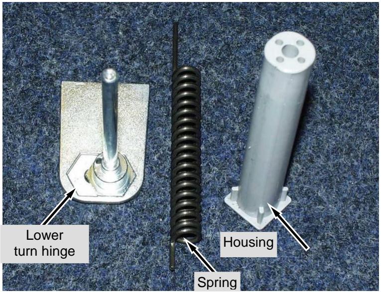
5.4 Door closing mechanism
Housing with spring:
- Changing the door hinges is described in the operating instructions.
- The ends of the spring must be inserted in the housing or turn hinge so that when mounting with the door closed, the turn hinge must be pre-tensioned by 90^ (in the closing direction).
text_image
Lower turn hinge Spring HousingFig. 5.4/1
6.0 Technical Data
| Fan: | Output: | approx. 20 Watt |
| Voltage: | 230 V/AC | |
| Speed: | 2,100 rev/min | |
| Direction of rotation: | right |
Sensor values:
| Temperature [°C] | Resistance value [kOhm] |
| +35 | 3.1 |
| +30 | 3.8 |
| +25 | 4.7 |
| +20 | 5.9 |
| +15 | 7.3 |
| +10 | 9.3 |
| +5 | 11.9 |
| 0 | 15.3 |
| -5 | 19.8 |
| -10 | 25.9 |
| -15 | 34.1 |
| -20 | 45.3 |
| -25 | 60.8 |
| -30 | 82.3 |
| -35 | 112.8 |
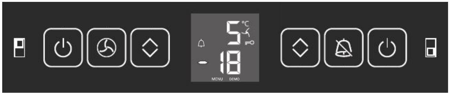
7.0 Service menu
The service menu may only be used by service engineers.
text_image
Control panel interface with icons for power, alarm, display, and function buttons7.1 Demo mode
| Step | Display | Action | Display following action | Testing option / Info |
| Activate demo mode | ||||
| 1a | Actual value | Press Up/Down (freezer compartment) + On/Off (freezer compartment) for 5 seconds | “d” flashes | Service menu activation |
| 2a | “d” flashes | Press alarm/audible alarm | “d!” | Demo mode selected |
| 3a | “d!” | Press alarm/audible alarm | Set target value | Demo mode ON |
| Deactivate demo mode (demo mode can only be deactivated by using the service menu, not by OFF/ON.) | ||||
| 1b | Set target value | Press Up/Down (freezer compartment) + On/Off (freezer compartment) for 5 seconds | “d” flashes | Service menu activation |
| 2b | “d” flashes | Press alarm/audible alarm | “d 0” | Demo mode selected |
| 3b | “d 0” | Press alarm/audible alarm | Control mode | Demo mode OFF |
| The appliance switches into the desired operating mode, either demo mode or control mode, as soon as “alarm/audible alarm” has been actuated. | ||||
7.2 Service mode
| Step | Display | Action | Display following action | Testing option / Info |
| Start service menu | ||||
| 1 | Actual value | Press Up/Down (freezer compartment) + On/Off (freezer compartment) for 5 seconds | “d” flashes | Service menu activation |
| Service mode-- control panel test | ||||
| 1 | “d” flashes | Press Up/Down (freezer compartment) | “P” flashes | Control panel test selected |
| 2 | “P” flashes | Press alarm/audible alarm | P | Control panel test activated |
| 3 | P | Press alarm/audible alarm | All LED segments light up | Control panel test active |
| 4 | All LED segments light up | ➢ Press all the buttons one after the other➢ Refrigerator compartment door open/closed➢ Freezer compartment door open/closed | Appliance logically off | |
| Service mode-- Testing electric loads -- | ||||
| 5 -> 11 | “d” flashes | Press Up/Down (freezer compartment) | “L-” flashes | Load test selected |
| 6 | “L-” flashes | Press alarm/audible alarm | L | Load test active |
| 7 | L | Press alarm/audible alarm | L | All off |
| 8 | L | Press alarm/audible alarm | L | Freezer compartment compressor ON |
| 9 | L | Press alarm/audible alarm | L | Fan ON |
| 10 | L | Press alarm/audible alarm | L | Compressor Refrigerator compartment on |
| 11 | L | Press On/Off 3 x (freezer compartment) | Control mode | |
7.3 Sensor menu
| Step | Display | Action | Display following action | Testing option / Info |
| Start service menu | ||||
| 1 | Actual value | Press Up/Down (freezer compartment) + On/Off (freezer compartment) for 5 seconds | “d” flashes | Service menu activation |
| Service mode-- sensor test | ||||
| 1 | “d” flashes | Press Up/Down (freezer compartment) | “E-” flashes | Control panel test selected |
| 2 | “E-” flashes | Press alarm/audible alarm | E | Control panel test activated |
| 3 | E | Press alarm/audible alarm | ‘18/ alternating with temperature | Refrigerator compartment air sensor |
| 4 | ‘1 | Press Up/Down (freezer compartment) | ‘23/ alternating with temperature | Refrigerator compartment evaporator sensor |
| 5 | ‘2 | Press Up/Down (freezer compartment) | ‘33/ alternating with temperature | Freezer compartment air sensor |
| 6 | ‘3 | Press Up/Down (freezer compartment) | ‘73/ alternating with temperature | Ambient temperature sensor |
| 7 | ‘7 | Press Up/Down (freezer compartment) | ‘8 | Refrigerator compartment door cL closed |
| 8 | ‘8 | Press Up/Down (freezer compartment) | ‘b | Freezer compartment door cL closed |
| 9 | ‘b | Press On/Off 3 x (freezer compartment) | Control mode | |
8.0 Table of error codes
| Error code | Defective component | Emergency mode |
| “F 1” flashes | Refrigerator compartment air sensor | 10 minutes ON / 20 minutes OFF |
| “F 2” flashes | Refrigerator compartment evaporator sensor | 10 minutes ON / 20 minutes OFF |
| “F 3” flashes | Freezer compartment air sensor | Continuous operation |