MPL520 - Serveur informatique MAXDATA - Notice d'utilisation et mode d'emploi gratuit
Retrouvez gratuitement la notice de l'appareil MPL520 MAXDATA au format PDF.


| Marque | MAXDATA |
| Modèle | MPL520 |
| Type de produit | Serveur informatique |
| Processeur | Support pour deux processeurs Intel Xeon (socket 604, FSB 800 MHz) |
| Chipset | Intel E7320 (MCH + ICH5-R) |
| Mémoire | 4 slots DDR SDRAM DIMM 184 broches, max 8 Go Registered ECC, DDR266/333 |
| Stockage | 2x Serial ATA (RAID 0/1), 2x ATA parallèles (Ultra 33/66/100), 1x disquette |
| Contrôleur graphique | ATI Rage XL intégré avec 8 Mo SDRAM |
| Réseau | 2x Gigabit Ethernet (Intel 82541 + PCI-Express) |
| USB | 4 ports USB 2.0 (2 arrière, 2 via header avant) |
| Slots d'extension | 2x PCI-X 64-bit/66 MHz, 2x PCI 32-bit/33 MHz, 1x x4 PCI-Express, 1x x16 PCI-Express (optionnel) |
| Gestion | Intel Server Management 8.0, diagnostics LED, Port-80 POST |
| Entretien | Température 10-30°C, humidité <70%, ventilation libre |
| Sécurité | Précautions ESD, installation sur surface stable, déconnexion AC avant intervention |
| Pièces détachées | Batterie lithium (CR2032), ventilateurs, processeurs, mémoire, disques durs |
| Réparabilité | Remplacement processeur, mémoire, carte PCI, batterie. Cavaliers pour effacer CMOS/mot de passe |
| Informations générales | Manuel système 31 pages, disponible en PDF |
FOIRE AUX QUESTIONS - MPL520 MAXDATA
Questions des utilisateurs sur MPL520 MAXDATA
0 question sur cet appareil. Repondez a celles que vous connaissez ou posez la votre.
Poser une nouvelle question sur cet appareil
Téléchargez la notice de votre Serveur informatique au format PDF gratuitement ! Retrouvez votre notice MPL520 - MAXDATA et reprennez votre appareil électronique en main. Sur cette page sont publiés tous les documents nécessaires à l'utilisation de votre appareil MPL520 de la marque MAXDATA.
MODE D'EMPLOI MPL520 MAXDATA
System Manual
1 Setting up the System 5
Server Position 5
Connecting the System 6
Back Panel Connectors 6
Powering up the System 7
2 Server Board Features 9
Server Board Connector and Component Locations 11
Configuration and BIOS Select Jumpers 12
Hardware Requirements 13
Processor 13
Memory 13
3 Server Board Installations and Upgrades 15
Before You Begin 15
Tools and Supplies Needed 15
Installing and Removing Memory 15
Installing DIMMs 15
Removing DIMMs 16
Installing or Replacing the Processor 17
Installing the Processor 17
Removing the Processor 19
Installing a PCI Card 19
Replacing the Backup Battery 20
4 Server Utilities 23
BIOS Setup. 23
Clearing the CMOS 24
Clearing the Password 24
LED Information 25
BIOS Error Messages 26
BIOS POST Beep Codes 27
BIOSRecoveryBeepCodes 28
5 Regulatory and Integration Information 29
Product Regulatory Compliance 29
Product Safety Compliance 29
Product EMC Compliance 29
Product Regulatory Compliance Markings 29
Electromagnetic Compatibility Notices 30
FCC (USA) 30
Europe (CE Declaration of Conformity) 30
Installation Precautions 30
Installation Requirements 31
Prevent Power Supply Overload 31
Place Battery Marking 31
Use Only for Intended Applications 31
Figures
- Back Panel Connectors 6
- The Controls 7
- Server Board Layout 11
- Configuration and BIOS Select Jumper Locations 12
- Installing Memory 15
- Opening Socket Lever and Attaching Processor 17
- Installing Heat Sink over Processor 18
- Replacing the Battery 21
Tables
- NIC LEDs. 6
- Server Board Features 9
- Configuration Jumper [J17] 12
- BIOS Select Jumper [J29] 12
- Keyboard Commands 23
- Keyboard Commands 25
- BIOS Error Messages 26
- Beep Codes 27
- BIOS Recovery Beep Codes 28
- Product Certification Markings 29
1 Setting up the System
Server Position
Please take note of the following criteria for creating a practical and safe workplace when setting up your computer:
The system can be used anywhere the temperature is suitable for people. However, rooms with humidity over 70% , and dusty or dirty areas are not appropriate. In addition, do not expose the server to any temperatures over +30^ or under +10^ .
Make sure that the cables connecting the server to peripheral devices are not tight.
Make sure that all power and connection cables are positioned so that they are not trip hazards.
When you save data to your server's hard disks or to a floppy disk, they are stored as magnetic information on the media. Make sure that they are not damaged by magnetic or electromagnetic fields.
Because the electronics in your computer can be damaged by jarring, no mechanical devices should be placed on the same surface as the server. This is especially important for impact printers whose vibrations could damage the hard disk.
Please take care to ensure a free air flow to the server at all times. Do not block the ventilation slots of the server case and particularly the power supplies. An insufficient air flow may damage the server and / or it's components.

ATTENTION
In order to fully separate the server from current, the power cord must be removed from the wall outlet.

ATTENTION
Safety instruction for upright devices: To ensure stability, the floor stands must be turned outwards.
Connecting the System
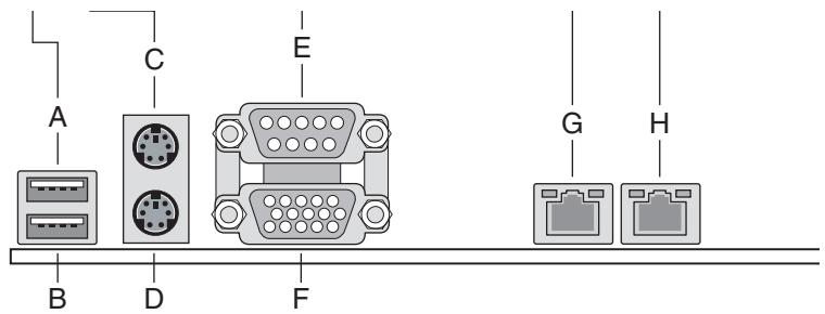
Back Panel Connectors
Figure 1. Back Panel Connectors
A. USB 1 E. Serial port A
B. USB 2 F. Video
C. Mouse G. NIC 2 (1Gbit. optional)
D. Keyboard H. NIC 1 (1Gbit)
The NIC LEDs at the right and left of each NIC provide the following information.
Table 1. NIC LEDs
| NIC | LED Color | LED State | Description |
| NIC1 (Gigabit) | Left LED | Off | No network connection |
| Solid Amber | Network connection in place | ||
| Blinking Amber | Transmit/receive activity | ||
| Right LED | Off | 10 Mbps connection (if left LED is on or blinking) | |
| Solid Amber | 100 Mbps connection | ||
| Solid Green | 1000 Mbps connection |
Powering up the System
At the front of the case, you can find the neccessary controls like power button, reset button and the HDD LEDs. Press the power button one time briefly in order to boot the server.
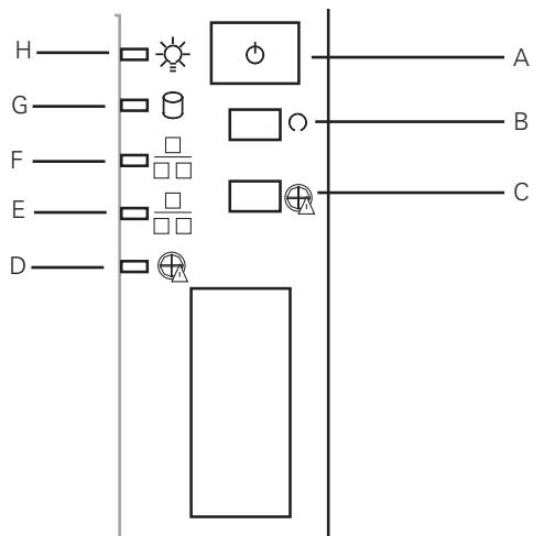
Figure 2. The Controls
A. Power switch
E. NIC1 LED
B. Reset switch
F. NIC2 LED
C. Disable Fan Warning
G. HDD LED
D. Fan Warning LED
H. Power LED
2 Server Board Features
This chapter briefly describes the main features of the server board. This chapter provides a list of server board features and diagrams showing the location of important components and connections on the server board.
The server board includes dual-channel Serial ATA and dual-channel Parallel ATA support. RAID 0 and 1 support is provided for Serial ATA drives.
Table 2 summarizes the major features of the server board.
Table 2. Server Board Features
| Feature | Description |
| Processors | Support for two Intel® Xeon™ processors in two 604-pin Intel® Xeon™ processor sockets with an 800 MHz system bus |
| Memory | Four 184-pin DDR SDRAM Dual Inline Memory Module (DIMM) socketsSupport for up to 8 GB Registered ECC system memorySupport for single-sided or double-sided DIMMs (DDR266/333) |
| Chipset | Intel® E7320 chipset, consisting of: ·Intel® 827320 Memory Controller Hub (MCH) ·Intel® 6300ESB I/O Controller Hub (ICH5-R) |
| Firmware Hub (FWH) | 8 Megabit Firmware Hub (FWH). |
| I/O Control | National PC87427 I/O controller chip |
| Peripheral Interfaces | ·Two external USB 2.0 ports on the back panel with an additional internal header that provides support for two additional USB ports for support at the front of the chassis (four total possible USB 2.0 ports) ·One serial port and one serial port header ·Two ATA interfaces with Ultra 33, 66 and 100 DMA mode ·Two serial ATA connectors with support for RAID 0 and 1 ·One floppy drive interface with support for one drive ·PS/2 keyboard and mouse ports |
| LAN | ·One Intel® 82541 Platform LAN Connect (PLC) device for 10/100/1000 Mbits/sec Ethernet LAN connectivity ·One PCI-Express device for 10/100/1000 Mbits/sec Ethernet LAN connectivity (optional) |
| Expansion Capabilities | Three / four independent PCI buses (one x4 PCI-Express; one x16 PCI-Express (optional); one 64-bit/66 MHz PCI-X, 3.3 V; one 32-bit/33 MHz PCI, 5 V) with five / six bus connectors: ·One x4 PCI-Express connector (optional) ·One x8 or one x16 PCI-Express connector ·Two 64-bit/66 MHz PCI-X connectors ·Two 32-bit/33 MHz PCI connectors |
| Integrated Capabilities | ·Integrated 2D/3D graphics controller: ATI Rage™ XL Video Controller with 8 MB of SDRAM |
| Fans | Support for up to six system fans and two processor fans |
continued
Server Board Features (Continued)
| BIOS | Intel/AMI BIOS with support for: • Advanced Configuration and Power Interface (ACPI) • 8 megabit symmetrical flash memory • Support for SMBIOS |
| Power Management | Support for ACPI: • Wake on USB, PCI, RS-232, PS/2, LAN, and control panel |
| Server Management | Intel® Server Management 8.0 support via the National Semiconductor PC87431M integrated management controller providing onboard plat-form instrumentation. |
| Leadership Technologies | • Intel® Light-Guided Diagnostics on some FRU devices (processors, power) • Port-80 Diagnostic LEDs displaying POST Codes |
Server Board Connector and Component Locations
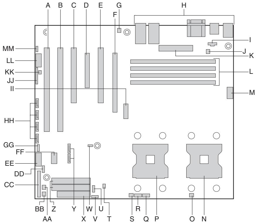
Figure 3. Server Board Layout
A. PCI-X Slot 1, 64-bit / 66 MHz
B. PCI-X Slot 2, 64-bit / 66 MHz
C. PCI Slot 3, 32-bit / 33 MHz
D. x4 PCI-Express Slot 4,
E. PCI Slot 5, 32-bit / 33 MHz
F. x16 PCI-Express Slot 6 (optional)
G. System Fan Header 2
H. Rear I/O (see figure 1 for details)
I. Auxiliary Power Connector
J. System Fan Header 1
K. Main Power Connector
L. DIMM Sockets (labeled from the top: 1B, 1A, 2B, 2A)
M. +12 V CPU Power Connector
N. Processor Socket 1
0. Processor 1 Fan Header
P. Processor Socket 2
Q. System Fan Header 6
R. System Fan Header 5
S. Processor 2 Fan Header
T. ATA Power Connector
U. Hot Swap Backplane Header
V. IPMB Connector
W. BIOS Select Jumper
X. Floppy Drive Connector
Y. SATA A1, A2 Connectors
Z. Primary and Secondary ATA Connectors
AA. System Fan Header 3
BB. System Fan Header 4
CC. Front Panel Connector
DD. SATA Backplane Header
EE. Front Panel USB Header
FF. OEM Remote Management Card Connector
GG. LCD Header
HH. SATA B1, B2, B3, B4 Connectors (optional)
II. Battery
JJ. Jumper Block
KK. Chassis Intrusion Header
LL. Serial B Header
MM. SCSI LED Connector
Configuration and BIOS Select Jumpers
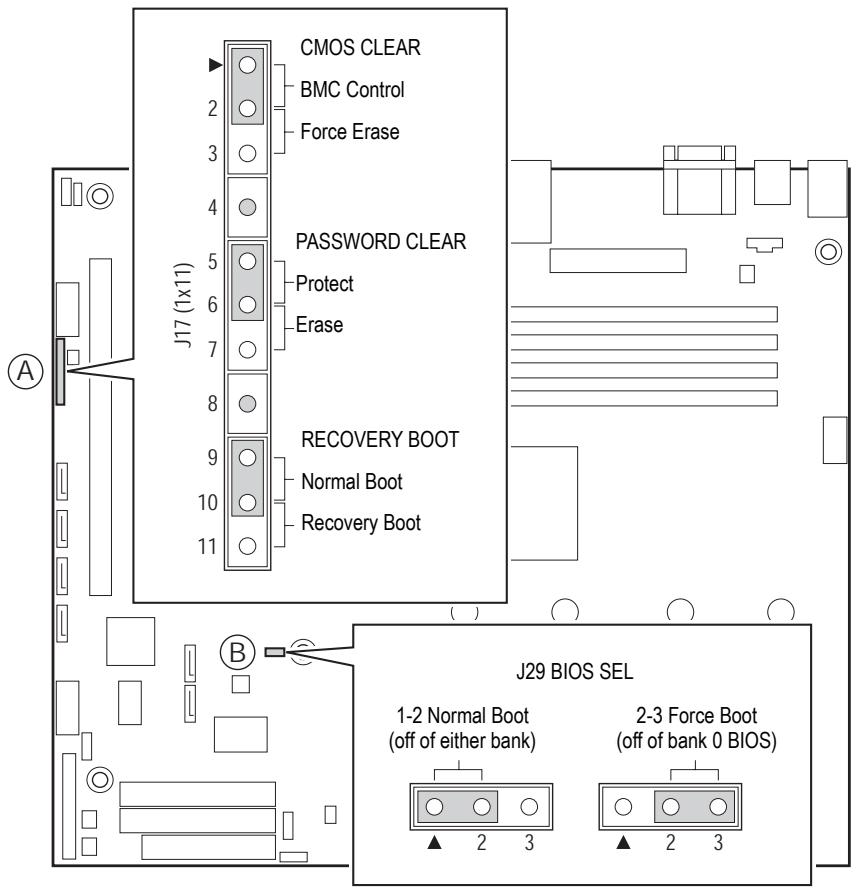
Figure 4. Configuration and BIOS Select Jumper Locations
Table 3. Configuration Jumper [J17]
| Jumper Name | Pins | What happens at System Reset |
| CMOS clear | 2-3 | If these pins are jumpered, the CMOS settings will be cleared on the next reset. These pins should be jumpered on 1-2 for normal operation. |
| Password Clear | 6-7 | If these pins are jumpered, administrator and user passwords will be cleared on the next reset. These pins should be jumpered on 5-6 for normal operation. |
| BIOS Recovery | 10-11 | If these pins are jumpered, the system will attempt to recover the BIOS by loading the BIOS code into the flash device from a floppy disk. This jumper is typically only used when the BIOS has become corrupted. These pins should be jumpered on 9-10 for normal operation. |
Table 4. BIOS Select Jumper [J29]
| Operation | Pins | What happens at System Reset |
| Normal Boot | 1-2 | If these pins are jumpered, the board will boot off of either BIOS (bank.0 or bank 1) depending on which is available first. |
| Force Boot | 2-3 | If these pins are jumpered, the board will boot off of bank 0 BIOS. |
Hardware Requirements
Processor
The server board is designed to support one or two Intel® Xeon™ processors utilizing an 800 MHz front side bus with frequencies starting at 2.8 GHz. Previous generations of the Xeon processor are not supported. The server board is designed to provide up to 120 A of current per processor. Processors with higher current requirements are not supported.
Memory
The server board provides four DDR266 / DDR333 DIMM sites in two DIMM banks. The maximum memory capacity is 8 GB for either DDR266 or DDR333 memory. Memory DIMM technologies supported are: 128 MB, 256 MB, 512 MB, 1 GB and 2 GB.
The minimum memory configuration is one DIMM, installed in DIMM socket 1B (the socket farthest from the processors). However, for optimum performance and dual-channel interleave operation, a minimum of two DIMMs should be installed. DIMMs on channel A are paired with DIMMs on channel B to configure 2-way interleaving.
Both DIMMS in Bank 1 (DIMM1B and DIMM1A) must be populated before any DIMMs are installed in Bank 2 (DIMM2B and DIMM2A). Bank 2 must be populated in pairs.
Both DIMMs in a bank must be identical (same manufacturer, CAS latency, number of rows, columns and devices, timing parameters etc.). Although DIMMs within a bank must be identical, the BIOS supports various DIMM sizes and configurations allowing the banks of memory to be different.
The mixing of DDR266 and DDR333 memory is supported on the server board. However, when mixing DIMM types, DDR333 will be treated as DDR266.
3 Server Board Installations and Upgrades
BeforeYouBegin
Before working with your server product, pay close attention to the installation precautions at the end of this manual.
Tools and Supplies Needed
- Phillips (cross head) screwdriver (#1 bit and #2 bit)
- Needle nosed pliers
- Antistatic wrist strap and conductive foam pad
Installing and Removing Memory
The silkscreen on the board for the DIMMs displays DIMM1B, DIMM1A, DIMM2B, and DIMM2A, starting from the inside of the board. DIMM2A is the socket closest to the processor socket.
Installing DIMMs
To install DIMMs, follow these steps:
- Observe the safety and ESD precautions at the end of this manual. See "Installation Precautions".
- Turn off all peripheral devices connected to the server. Turn off the server.
- Disconnect the AC power cord.
- Remove the server's cover. See your chassis documentation for instructions.
- Locate the DIMM sockets. See Figure 5.
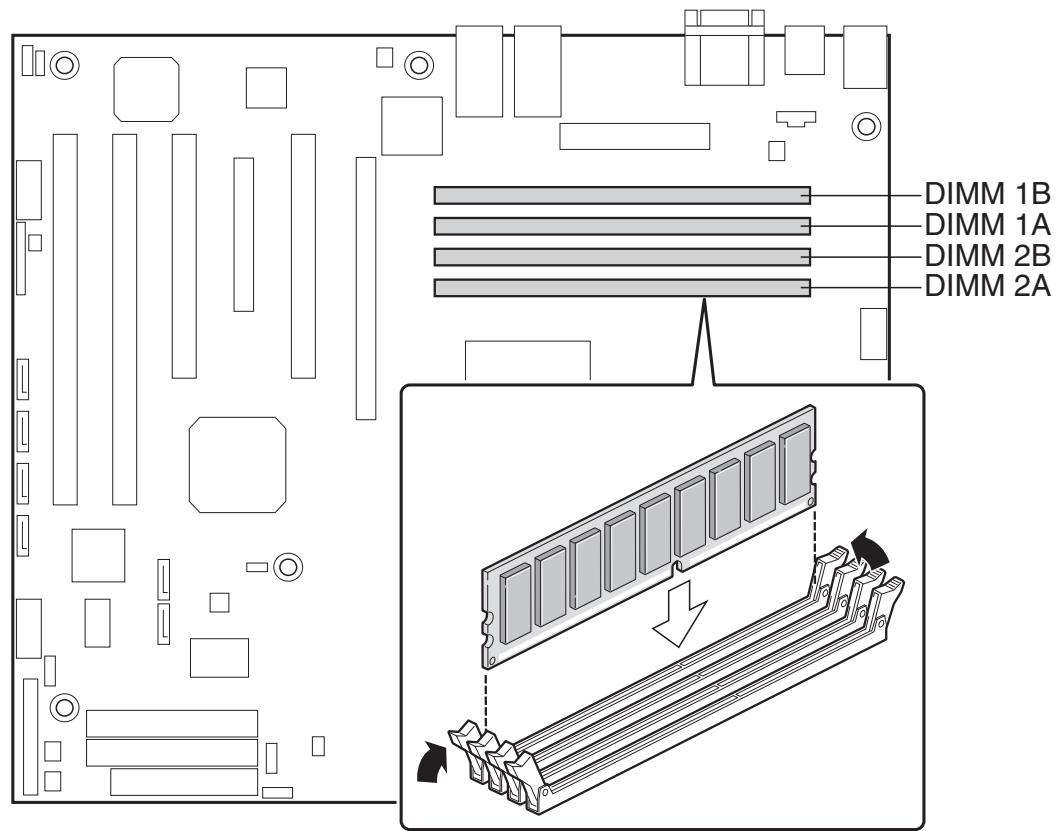
Figure 5. Installing Memory
- Make sure the clips at either end of the DIMM socket(s) are pushed outward to the open position.
- Holding the DIMM by the edges, remove it from its anti-static package.
- Position the DIMM above the socket. Align the small notch in the bottom edge of the DIMM with the keys in the socket (see inset in Figure 5.)
- Insert the bottom edge of the DIMM into the socket.
- When the DIMM is inserted, push down on the top edge of the DIMM until the retaining clips snap into place. Make sure the clips are firmly in place.
- Reconnect or replace any internal components you needed to disconnect or remove.
- Replace the server's cover. Reconnect any external components you needed to disconnect.
- Attach the AC power cord.
Removing DIMMs
To remove a DIMM, follow these steps:
- Observe the safety and ESD precautions at the end of this manual. See "Installation Precautions".
- Turn off all peripheral devices connected to the server. Turn off the server.
- Remove the AC power cord from the server.
- Remove the server's cover. See your chassis documentation for instructions.
- Gently spread the retaining clips at each end of the socket. The DIMM pops out of the socket.
- Hold the DIMM by the edges, lift it away from the socket, and store it in an anti-static package.
- Reconnect or replace any internal components you needed to disconnect or remove.
- Replace the server's cover. Reconnect any external components you needed to disconnect.
- Attach the AC power cord.
Installing or Replacing the Processor

NOTES
Use the instructions provided below to install or replace a processor instead of using the instructions that came with the processor.
If a single processor is to be used, it must be installed in the processor socket labeled CPU1. This socket is located closest to the corner of the server board.
When installing a second processor, verify that the processors are identical and of the same voltage and speed. Do not mix processors of different types or frequencies.

CAUTIONS
Processor must be appropriate: You may damage the server board if you install a processor that is inappropriate for your server.
ESD and handling processors: Reduce the risk of electrostatic discharge (ESD) damage to the processor by doing the following: (1) Touch the metal chassis before touching the processor or server board. Keep part of your body in contact with the metal chassis to dissipate the static charge while handling the processor. (2) Avoid moving around unnecessarily.
Installing the Processor
- Observe the safety and ESD precautions at the end of this manual. See "Installation Precautions".
- Turn off all peripheral devices connected to the server. Turn off the server.
- Remove power from your system by unplugging the AC power cord.
- Remove the chassis cover. See your chassis documentation for instructions.
- Lift the socket lever for the processor.
- Align the pins of the processor with the socket, and insert the processor into the socket. Lower the socket lever completely.

NOTE
Make sure the alignment triangle mark and the alignment triangle cutout align correctly. See Figure 6.
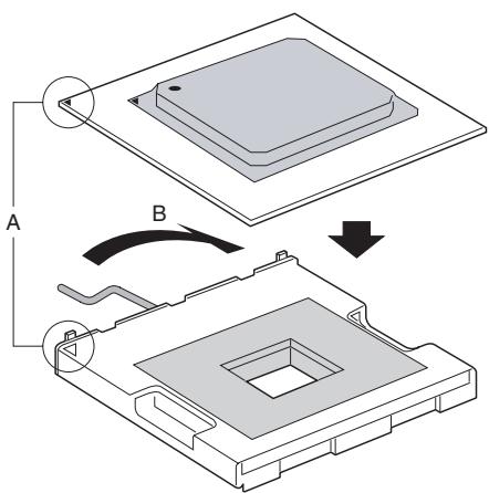
Figure 6. Opening Socket Lever and Attaching Processor
- Remove the heat sink from its packaging. The heat sink has thermal interface material (TIM) applied to the bottom of it. Be careful not to damage the TIM when you handle the heat sink.
- Set the heat sink on top of the processor, aligning the captive screws in the heat sink with the standoffs around the processor socket. See Figure 7, letter A. Your heat sink style may vary.
- Finger-tighten each captive screw, working around the heat sink. Tighten the screws evenly. Do not fully tighten one screw at a time. Continue to gradually and evenly tighten each screw, working around the heat sink. See Figure 7, letter B
- Server Chassis SC5275-E only: Connect the heat sink fan cable to the processor fan connector.
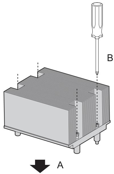
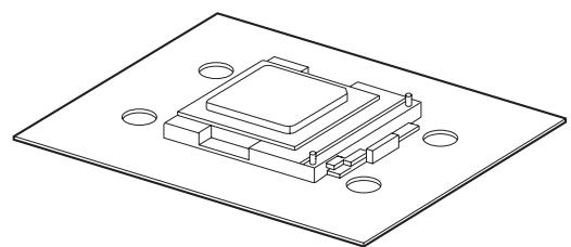
Figure 7. Installing Heat Sink over Processor
- Reconnect or replace any internal components you needed to disconnect or remove.
- Replace the server's cover. Reconnect any external components you needed to disconnect.
- Attach the AC power cord.
Removing the Processor
To remove the processor, follow these instructions:
- Observe the safety and ESD precautions at the end of this manual. See "Installation Precautions".
- Turn off all peripheral devices connected to the server. Turn off the server.
- Remove power from your system by unplugging the AC power cord.
- Remove the chassis cover. See your chassis documentation for instructions.
- Server Chassis SC5275-E only: Disconnect the processor fan cable.
- Fully loosen the four captive screws on the heat sink.
- Twist the heat sink to break the seal between the TIM and the processor.

CAUTIONS
Do not attempt to lift the heat sink from the processor without first twisting it to break the seal between the TIM and the processor. Lifting the heat sink without breaking the seal may damage the processor or the processor socket.
- Lift the heat sink from the processor.
- Lift the processor lever.
- Remove the processor.
- Reconnect or replace any internal components you needed to disconnect or remove.
- Replace the server's cover. Reconnect any external components you needed to disconnect.
- Attach the AC power cord.
Installing a PCI Card
The PCI slots support full-height add-in cards or low-profile PCI add-in cards with a standard full-height PCI mounting bracket.
- Observe the safety and ESD precautions at the end of this manual. See "Installation Precautions".
- Turn off all peripheral devices connected to the server. Turn off the server.
- Remove power from your system by unplugging the AC power cord.
- Remove the chassis cover. See your chassis documentation for instructions.
- Remove the screw that attaches the PCI bracket shield to the rear of the chassis to remove the shield. Retain the screw.
- Insert the PCI card into the PCI slot.
- Use the screw removed in step 1 to secure the PCI card to the chassis.
- Reconnect or replace any internal components you needed to disconnect or remove.
- Replace the server's cover. Reconnect any external components you needed to disconnect.
- Attach the AC power cord.
Replacing the Backup Battery
The lithium battery on the server board powers the RTC for up to 10 years in the absence of power. When the battery starts to weaken, it loses voltage, and the server settings stored in CMOS RAM in the RTC (for example, the date and time) may be wrong. Contact your customer service representative or dealer for a list of approved devices.
WARNING
Danger of explosion if battery is incorrectly replaced. Replace only with the same or equivalent type recommended by the equipment manufacturer. Discard used batteries according to manufacturer's instructions.
ADVARSEL!
Lithiumbatteri - Eksplosionsfare ved fejlagtig händtering. Udskiftning mA kun ske med batteri af samme fabrikat og type. Levér det brugte batteri til bage til leverandøren.
ADVARSEL
Danger of explosion if battery is incorrectly replaced. Replace only with the same or equivalent type recommended by the equipment manufacturer. Discard used batteries according to manufacturer's instructions.
WARNING
Explosionsfara vid felaktigt batteribyte. AnvändSAMMBatterityp ell er en ekvivalent typ som rekommenderas av apparattillverkaren. Kassera använt batteri enligt fabrikantens instruktion.
VAROITUS
Paristo voi rajähtä, jos se on virheellisesti asennettu. Vaihda paristo ainoastaan laitevalmistajan suosittelemaan tyyppiin. Hävitätä käytetty paristo valmistajan ohjeiden mukaisesti.
- Observe the safety and ESD precautions above and at the end of this book. See "Installation Precautions".
- Turn off all peripheral devices connected to the server. Turn off the server.
- Remove power from your system by unplugging the AC power cord.
- Remove the chassis cover. See your chassis documentation for instructions.
- Locate the battery. See Figure 8.
- Gently pull back on the metal tab to release the battery.
- Remove the battery from its socket.
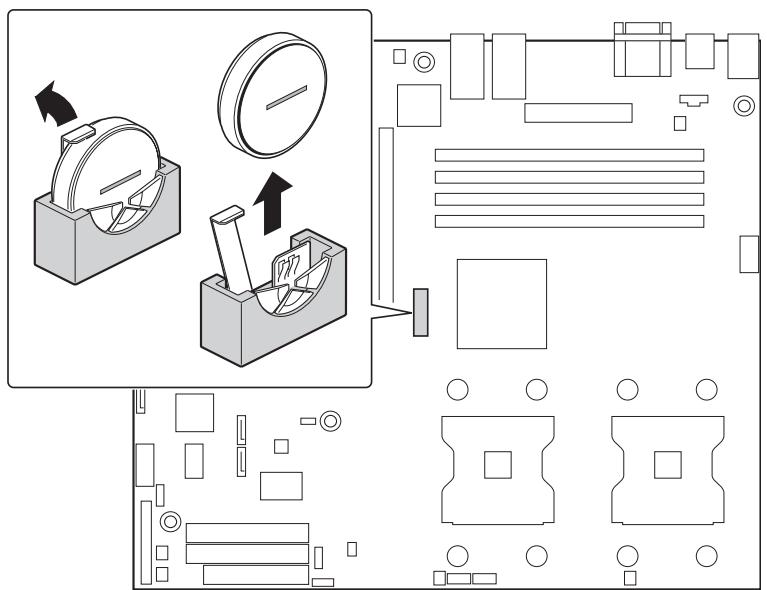
Figure 8. Replacing the Battery
- Dispose of the battery according to local ordinance.
- Remove the new lithium battery from its package, and, being careful to observe the correct polarity, insert it in the battery socket.
- Reconnect or replace any internal components you needed to disconnect or remove.
- Replace the server's cover. Reconnect any external components you needed to disconnect.
- Attach the AC power cord.
- Run Setup to restore the configuration settings to the RTC.
4 Server Utilities
BIOS Setup
Press <F2> to enter the BIOS Setup.
Table 5. BIOS Setup
| Press | Description |
| <F1> | Help - Pressing F1 on any menu invokes the general Help window. |
| ← → | The left and right arrow keys are used to move between the major menu pages. The keys have no affect if a submenu or pick list is displayed. |
| ↑ | Select Item up - The up arrow is used to select the previous value in a menu item's option list, or a value field pick list. Pressing the Enter key activates the selected item. |
| ↓ | Select Item down - The down arrow is used to select the next value in a menu item's option list, or a value field pick list. Pressing the Enter key activates the selected item. |
| F5/- | Change Value - The minus key or the F5 function key is used to change the value of the current item to the previous value. This key scrolls through the values in the associated pick list without displaying the full list. |
| F6/+ | Change Value - The plus key or the F6 function key is used to change the value of the current menu item to the next value. This key scrolls through the values in the associated pick list without displaying the full list. On 106-key Japanese keyboards, the plus key has a different scan code than the plus key on the other keyboard, but it has the same effect. |
| <Enter> | Execute Command - The Enter key is used to activate submenus when the selected feature is a submenu, or to display a pick list if a selected feature has a value field, or to select a sub-field for multi-valued features like time and date. If a pick list is displayed, the Enter key will undo the pick list, and allow another selection in the parent menu. |
| <Esc> | Exit - The ESC key provides a mechanism for backing out of any field. This key will undo the pressing of the Enter key. When the ESC key is pressed while editing any field or selecting features of a menu, the parent menu is re-entered. When the ESC key is pressed in any submenu, the parent menu is re-entered. When the ESC key is pressed in any major menu, the exit confirmation window is displayed and the user is asked whether changes can be discarded. |
| <F9> | Setup Defaults - Pressing F9 causes the following to appear: |
| Setup Confirmation | |
| Load default configuration now? | |
| [Yes] [No] | |
| If “Yes” is selected and the Enter key is pressed, all Setup fields are set to their default values. If “No” is selected and the Enter key is pressed, or if the ESC key is pressed, the user is returned to where they were before F9 was pressed without affecting any existing field values. |
continued
| <IF10> | Save and Exit - Pressing F10 causes the following message to appear: |
| Setup Confirmation | |
| Save Configuration changes and exit now? | |
| [Yes] [No] | |
| If “Yes” is selected and the Enter key is pressed, all changes are saved and Setup is exited. If “No” is selected and the Enter key is pressed, or the ESC key is pressed, the user is returned to where they were before F10 was pressed without affecting any existing values. | |
Clearing the CMOS
If you are not able to access the BIOS setup screens, the CMOS Clear jumper will need to be used to reset the configuration RAM. The CMOS Clear jumper is located on jumper block J17.
- Power down the system and disconnect the AC power.
- Open the server.
- Move the jumper from pins 1 and 2 to the Clear CMOS position, covering pins 2 and 3.
- Reconnect the AC power, power up the system.
- When the system begins beeping, power it down and disconnect the AC power.
- Return the CMOS Clear jumper to the original location, covering pins 1 and 2.
- Close the server chassis, reconnect the AC power and power up the system.
Clearing the Password
If the user or administrator password(s) is lost or forgotten, moving the password clear jumper into the "clear" position clears both passwords. The password clear jumper must be restored to its original position before a new password(s) can be set. The password clear jumper is located on jumper block J17.
- Power down the system and disconnect the AC power.
- Open the server chassis.
- Move the jumper from pins 5 and 6 to the Clear Password position, covering pins 6 and 7.
- Reconnect the AC power, power up the system.
- Power down the system and disconnect the AC power.
- Return the Password Clear jumper to the original location, covering pins 5 and 6.
- Close the server chassis.
LED Information
The MAXDATA Server Board includes LEDs that can aid in troubleshooting your system. A table of these LEDs with a description of their use is listed below.
Table 6. Keyboard Commands
| LED Name | Function | Location | Color | Correction |
| System fault | Visible fault warning | Control panel and board rear left corner | Green or Amber | • On = No Fault • Green Blink = degraded • Amber = critical error or non-recoverable • Amber blink = non-critical |
| ATA activity | Control panel | Control panel and board left side | Green | Blinking = Activity. No action required. |
| Memory fault 1-6 | Identify failing memory module | DIMM end front of board | Amber | On = Fault |
| POST code 1-4 (LSB, bit1, bit2, MSB) | Display boot 80 POST code | Left rear of board | Each LED can be Off, Green, Amber, Red | See the POST code table |
| Fan Pack Fault | Warn on fan failure | Front center board | Amber | On = Fault |
| CPU 1 & 2 Fan Fault | Identify fan failure | Front center board | Amber | On = Fault |
| CPU 1 & 2 Fault | Identify processor failure | 1" behind processor socket | Amber | On = Fault |
| 5 V Standby | Identify 5 V standby power on state | Front left board | Amber | On = 5 V standby power on |
| Power LED | Identify the power state of the system | Control panel | Green | • Off = Power is off (off or S5) • On = Power on or S0) • Slow Blink = Low power state (S1 – S3) |
BIOS Error Messages
When a recoverable error occurs during the POST, the BIOS displays an error message describing the problem (see Table 7).
Table 7. BIOS Error Messages.
| Error message | Explanation |
| GA20 Error | An error occurred with Gate A20 when switching to protected mode during the memory test. |
| Pri Master HDD Error | Could not read sector from corresponding drive. |
| Pri Slave HDD Error | |
| Sec Master HDD Error | |
| Sec Slave HDD Error | |
| Pri Master Drive - ATAPI Incompatible | Corresponding drive is not an ATAPI device. Run Setup to make sure device is selected correctly. |
| Pri Slave Drive - ATAPI Incompatible | |
| Sec Master Drive - ATAPI Incompatible | |
| Sec Slave Drive - ATAPI Incompatible | |
| A: Drive Error | No response from diskette drive. |
| CMOS Battery Low | The battery may be losing power. Replace the battery soon. |
| CMOS Display Type Wrong | The display type is different than what has been stored in CMOS. Check Setup to make sure type is correct. |
| CMOS Checksum Bad | The CMOS checksum is incorrect. CMOS memory may have been corrupted. Run Setup to reset values. |
| CMOS Settings Wrong | CMOS values are not the same as the last boot. These values have either been corrupted or the battery has failed. |
| CMOS Date/Time Not Set | The time and/or date values stored in CMOS are invalid. Run Setup to set correct values. |
| DMA Error | Error during read/write test of DMA controller. |
| FDC Failure | Error occurred trying to access diskette drive controller. |
| HDC Failure | Error occurred trying to access hard disk controller. |
| Checking NVRAM...... | NVRAM is being checked to see if it is valid. |
| Update OK! | NVRAM was invalid and has been updated. |
| Updated Failed | NVRAM was invalid but was unable to be updated |
| Keyboard Error | Error in the keyboard connection. Make sure keyboard is connected properly. |
| KB/Interface Error | Keyboard interface test failed |
| Memory Size Decreased | Memory size has decreased since the last boot. If no memory was removed, then memory may be bad. |
| Memory Size Increased | Memory size has increased since the last boot. If no memory was added, there may be a problem with the system. |
| Memory Size Changed | Memory size has changed since the last boot. If no memory was added or removed, then memory may be bad. |
| No Boot Device Available | System did not find a device to boot |
| Off Board Parity Error | A parity error occurred on an off-board card. This error is followed by an address. |
continued
BIOS Error Messages (Continued)
| Error message | Explanation |
| On Board Parity Error | A parity error occurred in onboard memory. This error is followed by an address. |
| Parity Error | A parity error occurred in onboard memory at an unknown address. |
| NVRAM / CMOS / PASSWORD cleared by Jumper | NVRAM, CMOS, and passwords have been cleared. The system should be powered down and the jumper removed. |
| <CTRL_N> Pressed | CMOS is ignored and NVRAM is cleared. User must enter Setup. |
BIOS POST Beep Codes
The table below lists the POST error beep codes. Prior to system video initialization, the BIOS uses these beep codes to inform users of error conditions. The beep code occurs only when a critical error occurs or when the BIOS fails to boot to the operating system. Please note that not all error conditions are supported by BIOS beep codes.
Table 8. Beep Codes
| Number of Beeps | Description |
| 1 | Refresh failure |
| 2 | Parity cannot be reset |
| 3 | First 64 Kb memory failure |
| 4 | Timer not operational |
| 5 | Processor failure (Reserved; not used) |
| 6 | 8042 GateA20 cannot be toggled (memory failure or not present) |
| 7 | Exception interrupt error |
| 8 | Display memory R/W error |
| 9 | (Reserved; not used) |
| 10 | CMOS Shutdown register test error |
| 11 | Invalid BIOS (such as, POST module not found) |
BIOS Recovery Beep Codes
Table 9. BIOS Recovery Beep Codes
| Beeps | Reason |
| 1 | One long beep – video is active. |
| 1-2 | One long beep and two short beeps: Insert the BIOS recovery diskette. |
An error or warning condition at boot can result in a series of beeps being issued known as „beep codes". These beeps have a code that identifies system or PCI card events. For example, some Intel® RAID cards have beep codes. Before checking for a system beep code error make sure the PCI card is not causing the beeping.
5 Regulatory and Integration Information
Product Regulatory Compliance
Product Safety Compliance
The server board complies with the following safety requirements:
- UL 1950 - CSA 950 (US/Canada)
EN 60 950 (European Union)
IEC60950(International) - CE - Low Voltage Directive (73/23/EEC) (European Union)
EMKO-TSE (74-SEC) 207/94 (Nordics)
GOST R 50377-92 (Russia)
Product EMC Compliance
The mainboard has been tested and verified to comply with the following electromagnetical compatibility (EMC) regulations when installed in a compatible Maxdata host system.
FCC (Class A Verification) - Radiated & Conducted Emissions (USA)
ICES-003 (Class A) - Radiated & Conducted Emissions (Canada)
CISPR 22, 3rd Edition (Class A) - Radiated & Conducted Emissions (International)
EN55022 (Class A) - Radiated & Conducted Emissions (European Union)
EN55024 (Immunity) (European Union)
CE - EMC Directive (89/336/EEC) (European Union)
Product Regulatory Compliance Markings
This product is marked with the following Product Certification Markings:
Table 10. Product Certification Markings
| UL Recognition Mark | ®C US |
| CE Mark | CE |
Electromagnetic Compatibility Notices
FCC (USA)
This device complies with Part 15 of the FCC Rules. Operation is subject to the following two conditions: (1) this device may not cause harmful interference, and (2) this device must accept any interference received, including interference that may cause undesired operation.
This equipment has been tested and found to comply with the limits for a Class A digital device, pursuant to Part 15 of the FCC Rules. These limits are designed to provide reasonable protection against harmful interference in a residential installation. This equipment generates, uses, and can radiate radio frequency energy and, if not installed and used in accordance with the instructions, may cause harmful interference to radio communications. However, there is no guarantee that interference will not occur in a particular installation. If this equipment does cause harmful interference to radio or television reception, which can be determined by turning the equipment off and on, the user is encouraged to try to correct the interference by one or more of the following measures:
Reorient or relocate the receiving antenna.
- Increase the separation between the equipment and the receiver.
- Connect the equipment to an outlet on a circuit other than the one to which the receiver is connected.
- Consult the dealer or an experienced radio/TV technician for help.
Any changes or modifications not expressly approved by the grantee of this device could void the user's authority to operate the equipment. The customer is responsible for ensuring compliance of the modified product.
Only peripherals (computer input/output devices, terminals, printers, etc.) that comply with FCC Class A or B limits may be attached to this computer product. Operation with noncompliant peripherals is likely to result in interference to radio and TV reception. All cables used to connect to peripherals must be shielded and grounded. Operation with cables, connected to peripherals, that are not shielded and grounded may result in interference to radio and TV reception.
Europe (CE Declaration of Conformity)
This product has been tested in accordance to, and complies with the Low Voltage Directive (73/23/ EEC) and EMC Directive (89/336/EEC). The product has been marked with the CE Mark to illustrate its compliance.
Installation Precautions
When you install and test the server board, observe all warnings and cautions in the installation instructions.
To avoid injury, be careful of:
Sharp pins on connectors
Sharp pins on printed circuit assemblies
- Rough edges and sharp corners on the chassis
- Hot components (like processors, voltage regulators, and heat sinks)
- Damage to wires that could cause a short circuit
Observe all warnings and cautions that instruct you to refer computer servicing to qualified technical personnel.
Installation Requirements

CAUTION
Follow these guidelines to meet safety and regulatory requirements when installing this board assembly.
Read and adhere to all of these instructions and the instructions supplied with the chassis and associated modules. If the instructions for the chassis are inconsistent with these instructions or the instructions for associated modules, contact the supplier's technical support to find out how you can ensure that your computer meets safety and regulatory requirements. If you do not follow these instructions and the instructions provided by chassis and module suppliers, you increase safety risk and the possibility of noncompliance with regional laws and regulations.
Prevent Power Supply Overload
Do not overload the power supply output. To avoid overloading the power supply, make sure that the calculated total current loads of all the modules within the computer is less than the output current rating of each of the power supplies output circuits.
Place Battery Marking
There is insufficient space on this server board to provide instructions for replacing and disposing of the battery. For system safety certification, the following statement or equivalent statement may be required to be placed permanently and legibly on the chassis near the battery.

CAUTION
Risk of explosion if battery is incorrectly replaced.
Replace with only the same or equivalent type recommended by the manufacturer. Dispose of used batteries according to the manufacturer's instructions.
Use Only for Intended Applications
This server board was evaluated as Information Technology Equipment (I.T.E.) for use in computers that will be installed in offices, homes, schools, computer rooms, and similar locations. The suitability of this product for other applications or environments, (such as medical, industrial, alarm systems, test equipment, etc.) may require further evaluation.