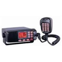
JMC RT-2500 - Radio VHF marine fixe RADIOLA - Notice d'utilisation et mode d'emploi gratuit
Retrouvez gratuitement la notice de l'appareil JMC RT-2500 RADIOLA au format PDF.


| Type de produit | Radio VHF marine fixe avec DSC |
| Marque | RADIOLA / JMC |
| Modèle | RT-2500 |
| Catégorie | Radio VHF marine fixe |
| Dimensions (L x H x P) | 160 x 63 x 168 mm (sans dissipateur) |
| Poids | 1,0 kg |
| Alimentation | 13,8 V DC négative à la masse ; consommation max 5,6 A (émission 25 W) |
| Plage de fréquences (émission) | 156 à 158 MHz |
| Plage de fréquences (réception) | 156 à 163 MHz |
| Puissance d'émission | 1 W ou 25 W (sélectionnable) |
| Canaux | Canaux VHF maritimes internationaux (01-28, 60-88) + canal 70 DSC |
| Fonctions principales | Appel sélectif numérique (DSC) individuel, groupe, tous navires ; demande/envoi de position ; réception d'appels géographiques ; veille triple (canal 16, 9 et courant) ; balayage mémoire ; horloge alarme ; mode eaux intérieures/maritime ; ATIS |
| Indicateurs | TX, TRI, HI, LO, MEM, DSC, GPS, alarme, affichage canal |
| Microphone | Microphone à condensateur 2k, 15 touches, étanche |
| Haut-parleur | Haut-parleur avant interne (cône mylar 1,82 pouce, 8 Ω) |
| Étanchéité | IPX7 (immergeable jusqu'à 1 m pendant 30 minutes) |
| Température de fonctionnement | -15 °C à +55 °C |
| Entretien et nettoyage | Nettoyer avec un chiffon doux et sec ; éviter les solvants ; vérifier périodiquement l'antenne et les connexions |
| Sécurité | Fusible de protection (250 V 6 A, à action rapide) ; arrêt automatique en cas de surchauffe ; émission interdite sans antenne |
| Pièces détachées et réparabilité | Contacter le revendeur agréé JMC pour les pièces et réparations ; support technique disponible |
| Accessoires inclus | Support de montage, câble CC, microphone, câble d'accessoires, fusible de rechange |
| Certifications | CE (RTTE 1999/5/EC), IPX7, conforme EN 300 698, EN 301 025, EN 60945 |
FOIRE AUX QUESTIONS - JMC RT-2500 RADIOLA
Questions des utilisateurs sur JMC RT-2500 RADIOLA
0 question sur cet appareil. Repondez a celles que vous connaissez ou posez la votre.
Poser une nouvelle question sur cet appareil
Téléchargez la notice de votre Radio VHF marine fixe au format PDF gratuitement ! Retrouvez votre notice JMC RT-2500 - RADIOLA et reprennez votre appareil électronique en main. Sur cette page sont publiés tous les documents nécessaires à l'utilisation de votre appareil JMC RT-2500 de la marque RADIOLA.
MODE D'EMPLOI JMC RT-2500 RADIOLA
Summary Operating Manual
for
Model RT-2500
Fixed Type VHF Marine with DSC, Submersible & 15 Key Microphone

Japan Marica Co., Ltd.
36-2-1001 UDAGAWA-CHO, SHIBUYA-KU, TOKYO 150-0042, JAPAN
PHONE: 81-3-3461-3606 FAX: 81-3-3496-2078
www.japan-marina.co.jp sales@japan-marina.co.jp
Contents
Included with your RT-2500 3
Controls and Indicators. 4
Installation 8
Choosing a Location. 8
Engine Noise Suppression 9
Antenna Considerations 9
Antenna Selection and Installation 9
Installing the RT-2500. 10
Operation 11
Power On/Off 11
Last Channel Memory 11
Squelch 12
Coast Guard Channel 16/Channel 9 Communications 13
Triple Watch 13
Manual Tuning 14
MEM (Entering channel numbers into Memory Scan) 14
Triple Watch Scan 14
Normal Scan. 14
Transmitting 15
Setting TX Output 15
Distress 16
Marine Distress Procedure 17
Menu Operation 18
Digital Selective Calling (DSC) 18
Individual 18
Group 19
All Ships 20
Position Request 21
Position Send 23
Standby 24
Call Wait. 25
Geographical Call 26
Setup 27
Alarm Clock 27
Local Time Adjust 30
Daylight Savings On/Off 31
Directory 32
Auto Channel Switch 36
Position Reply 37
CH Tag 39
Group MMSI. 41
User MMSI 42
ATIS ID 43
System 44
Contrast. 44
Lamp Adjust 45
Key Beep 46
Switching the Inland Waterway Mode/Seagoing Mode 47
Displaying GPS information. 47
Setting Position for Distress Call 47
NMEA Technical Setup 48
Optional Accessories 48
VHF FM Marine Radio Telephone Channel and Functions (International Channels) 49
Specification 50
Troubleshooting 51
Care and Maintenance 52
EC Declaration of Conformity 53
The Jmc RT-2500 VHF marine radio has been designed to give you a rugged, reliable instrument that will provide you with years of trouble-free service.
With proper care and maintenance, your marine radio could outlast your present vessel and serve you well on-board. The full features and flexibility designed into this quality transceiver will prevent it from becoming obsolete regardless of changes in craft or geographic locations.
The RT-2500 is of all solid-state design with conservatively rated, rugged components and materials compatible with the marine environment. The transceiver utilizes a number of gaskets, sealing rings, waterproof membranes, and other sealants to effect a waterproof housing for protection of the electronics. It meets the most stringent IPX7 waterproof specification. The unit may be mounted in any number of convenient locations on your vessel by utilizing the optional flash mount bracket (Black - FMB322B).
You are encouraged to thoroughly read the rest of this Operating Guide to acquaint yourself with the characteristics and operation of your transceiver so that you can contribute to the longevity of your investment.
Keep your receipt as proof-of-purchase in case warranty service is required.
Features, specifications, and availability of optional accessories are all subject to change without notice.
Note: RT-2500 meets IPX7 requirements.
Included with your RT-2500
RT-2500 Owner's Manual
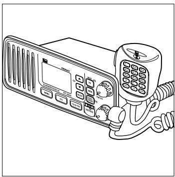
RT-2500 Radio
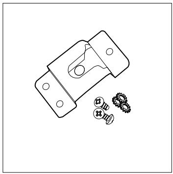
Microphone Hanger and Screws

Mounting Bracket and Knobs
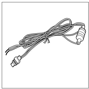
DC Cord
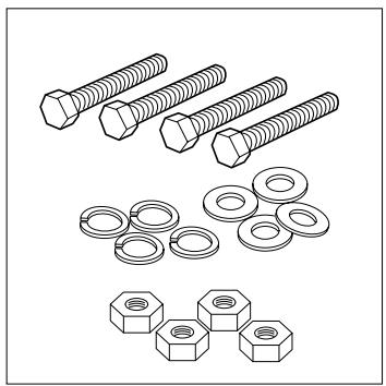
Mounting Hardware
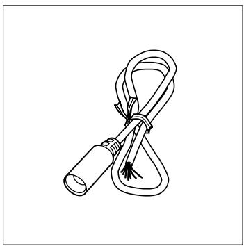
Accessory Cable
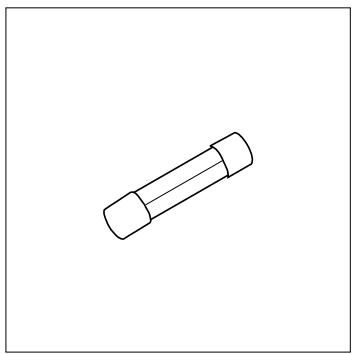
Spare Fuse 250V6A
Front panel/Microphone
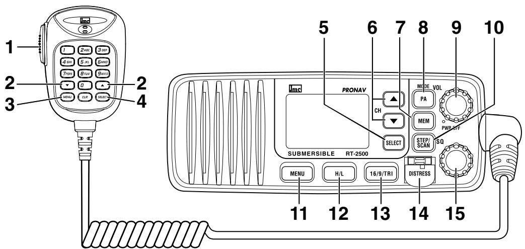
- PTT Switch - Press to transmit and release to receive.
2.6. CHANNEL/▲▼- These keys are used to change the channel number up/down. These buttons are also used to move the cursor in Menu mode.
3.11. MENU - Press this key to enter the Menu mode.
4.5. SELECT - In the Menu mode this is used to select the menu options. - STEP/SCAN - Press this key to activate the step operation. Every time this key is pushed, the radio will step to the next channel that has placed into Memory. Pressing and holding this key for 2 seconds will activate the channel scan feature.
- MEM - Pressing will place the currently selected channel into Memory.
- PA/MODE - Press this key to enable the PA (Public Address) feature. Pressing and holding this key will switch between Inland Waterway Mode and Seagoing mode.
- PWR/VOL (On/Off/Volume) - Turns the unit On or Off and adjusts the speaker volume.
- HI/LO - Press this key to change the transmit power to either High or Low.
- 16/9/TRI - Press this key instantly change to Channel 16, Channel 9 or current channel. Pressing and holding this key for 2 seconds will activate the triple Watch Feature.
- DISTRESS - Press this key to send a signal of distress in case of emergency.
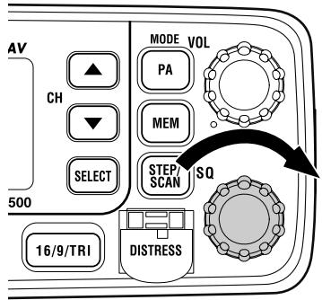
- SQ - Rotate this knob eliminate background noise when a signal is not being received.
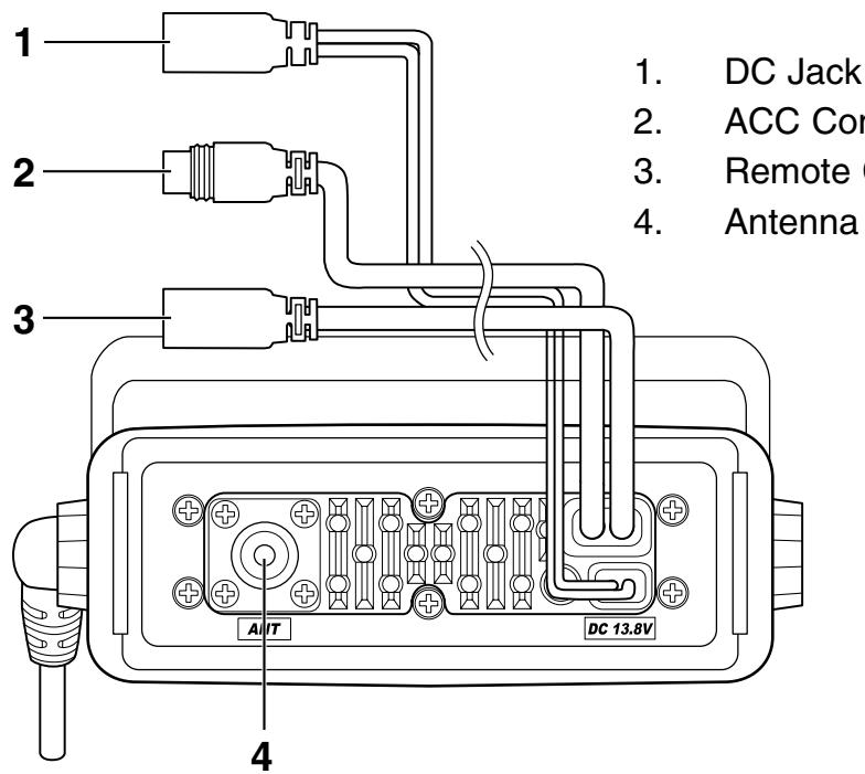
Rear Panel Connectors
ACC Connector
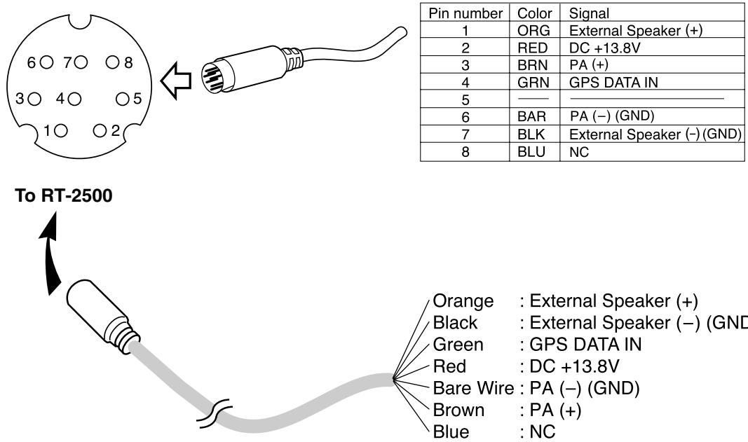
Note: DC13.8V and GND are for GPS ANT.
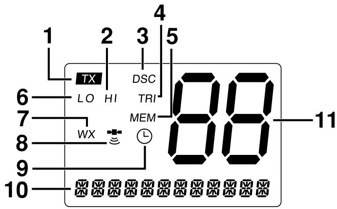
- TX (Transmit) - Indicates transmitting.
- HI (High) - Indicates transmit output is 25 Watts.
- DSC - Indicates the radio is in the DSC mode.
- TRI (Triple Watch) - Indicates Triple Watch Mode is in effect.
- MEM (Memory) - Indicates Memory Scan Mode status for each channel selected.
- LO (Low) - Indicates transmit output is 1 Watt.
- WX - It blinks when the radio in the Inland Waterway mode.
- (GPS Icon) - Indicates the following GPS receiving statuses; - Blinking: No GPS receiver is connected at power-up or no valid position fix is available for more than 4 hours continuously.
- Animating: GPS receiver is receiving valid position data.
- Stationary: GPS receiver is waiting for a Valid position fix.
- None: GPS receiver stops receiving data.
- (Alarm Icon) - It appears when the alarm clock is set.
- CH TAG - This area is used for Channel Tag, Menu, and message of DSC, GPS. These messages will continually scroll from right to the left.
- Channel Display - Indicates Channel Number in use.
Flow Chart for Menu Operation
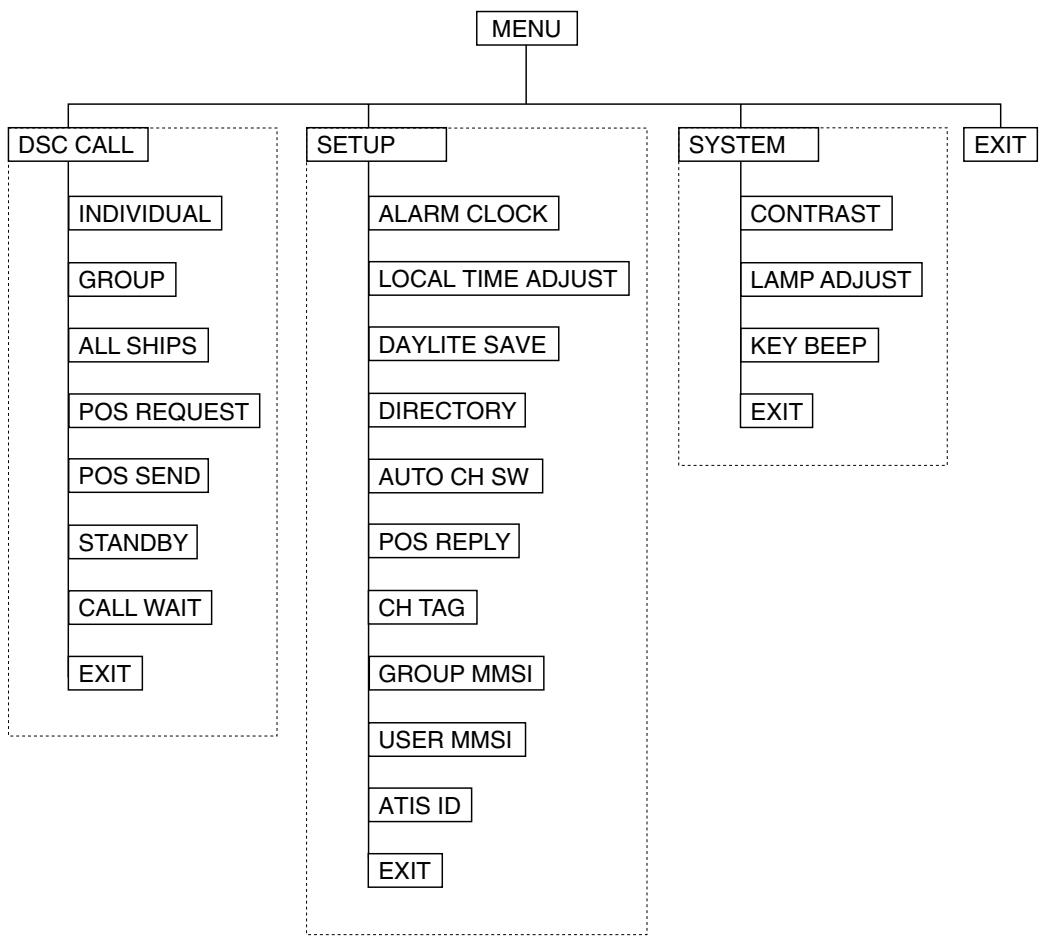
NOTES: "POS SEND", "LOCAL TIME ADJUST", "DAYLITE SAVE", and "ALARM CLOCK" are not displayed in Menu when GPS module is not connected.
When the radio is in one of the following modes: Channel 16/9 mode, Scan Mode, or Triple Watch mode, and the user presses the Menu key, all of these modes are cancelled.
The Menu mode will be cancelled if the radio receives a DSC call or "EXIT" is selected.
Installation
Caution: The RT-2500 will only operate with a nominal 12 volt negative ground battery system.
It is important to carefully determine the most suitable location for your radio on your vessel. Electrical, mechanical, and environmental considerations must all be taken into account. You should select the optimum relationship among these considerations.
Keep in mind the flexibility designed into the RT-2500 so that you can most conveniently use it. Features which should be considered are:
- The universal mounting bracket may be installed on either the top or bottom of a shelf, on a bulkhead, or for overhead mounting.
- The REMOTE speaker wires can be used with an auxiliary speaker.
- All connections are "plug-in" type for easy removal of the radio.
- Front fire internal speaker allows convenient in-dash mounting using the optional bracket (Black - FMB322B).
Choosing a Location
Some important factors to consider in selecting the location for your RT-2500.
- Select a location that is free from spray and splash.
- Keep the battery leads as short as possible. Direct connection to the battery is most desirable. If direct connection can not be made with the supplied power lead, any extension should be made with #10 AWG wire. Long extensions should use larger gauge wire.
- Keep the antenna lead as short as possible. Long antenna leads can cause substantial loss of performance for both receiving and transmitting.
- Locate your antenna as high as possible and clear from metal objects. The reliable range of coverage is a direct function of the antenna height.
- Select a location that allows free air flow around the heat sink on the rear of the radio.
- Select a location well away from the ship's compass. Auxiliary speakers also should be located away from the compass.
Engine Noise Suppression
Interference from the noise generated by the electrical systems of engines is sometimes a problem with radios. The RT-2500 has been designed to be essentially impervious to ignition noise and alternator noise. However, in some installations it may be necessary to take measures to further reduce the effect of noise interference. All DC battery wires, antenna lead, and accessory cables should be routed away from the engine and engine compartment, and from power cabling carrying high currents.
In severe cases of noise interference, it may be necessary to install a noise suppression kit. Contact your Dealer for more information.
Antenna Considerations
A variety of antennas are available from a number of quality suppliers. It is recommended you draw upon the advice of your dealer in determining a suitable antenna for your vessel and range requirements.
In general, communication range is increased by using a high-gain antenna placed as high as possible above the water line. Antennas should be located away from metal objects. Antennas should not have excessively long coaxial feed cables.
Antenna Selection and Installation
RT-2500 has been designed to accommodate all of the popular marine VHF antennas. However, the selection and the installation of the antenna is the responsibility of the user or installer.
The antenna used with this radio should be installed using the following guidelines to insure a suitable distance between the antenna and persons close by.
Small whip antennas (3 dB) or smaller should be installed keeping at least three feet separation distance between the radiating element and people.
Larger antennas (6 dB or 9 dB) should be installed keeping at least a six foot separation distance.
No person should touch the antenna or come into the separation distance when the radio is transmitting.
Installing the RT-2500
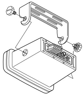
After you have carefully considered the various factors affecting your choice of location, position the radio (with the bracket, microphone, power cord, antenna and any auxiliary cables installed) into the selected location to assure there is no interference with the surrounding items. Mark the location of the mounting bracket. Remove the bracket from the radio and use it as a template to mark the holes to be drilled for the mounting hardware. Drill the holes and mount the bracket with hardware compatible with the material of the mounting surface.
Note: This HEXAGON HEAD BOLT is only for mounting the bracket with hardware. Do not use it for installing the radio in the mounting bracket.

Connect the red wire of the supplied power cord to the positive (+) battery supply. Connect the black wire of the power cord to the negative (-) battery supply. The power cord is equipped with a fuse to protect the radio. Use only a six (6) ampere fast blow fuse for replacement. Connect the power cord to the keyed connector on the power "pigtail".
Connect the antenna and all other auxiliary cables and accessories. Install the radio in the mounting bracket and connect all cables and accessories to the appropriate jacks and connectors.
Note: Do not use any other mounting knobs than the ones enclosed. Do not insert the knobs without attaching the bracket.
Operation
POWER On/Off
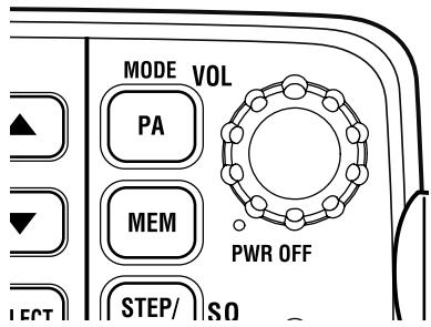
Turn the unit On by rotating the PWR/VOL control clockwise.
Adjust the volume to a comfortable level.
When you turn the unit On, you will hear a beep, and the greeting message below appears on the LCD for 3 seconds.
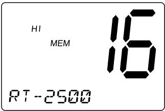
Note: When you turn On the radio for the first time after purchase, the channel 16 will appear on the LCD.
Last Channel Memory
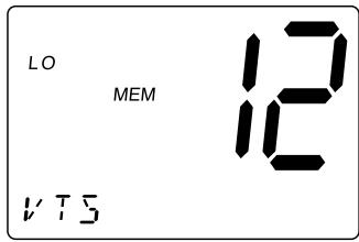
The RT-2500 memorizes the last channel selected before you turn Off the radio. For example, if you turn Off the radio on CH 12, it will be on that channel when turned back On.
Note: In order for the last channel to be memorized, you must have the radio on that channel for 3 seconds.
SQUELCH
Turn SQ fully clockwise. This raises the "Squelch Gate" so high that only very strong signals can get through.
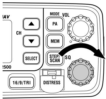
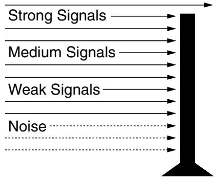
Turn SQ fully counterclockwise until you hear a hiss. This lowers the "Squelch Gate" so that everything gets through - noise, weak signals, and strong signals.
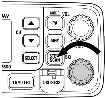
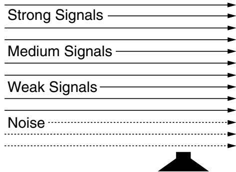
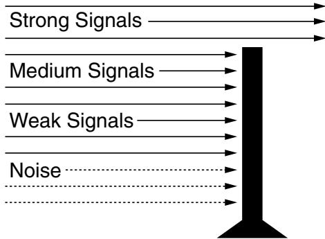
Turn SQ back clockwise until the hiss stops. Now the "Squelch Gate" allows only strong signals through.
COAST GUARD CHANNEL 16/CHANNEL 9 COMMUNICATIONS
To access Coast Guard Channel 16 or Channel 9 communications, press 16/9/TRI. You can access Coast Guard 16 CH instantly while tuned to another channel. Press 16/9/TRI again for Channel 9 Calling communications. Press 16/9/TRI a third time to return to the channel selected prior to accessing Coast Guard Channel 16/Channel 9 communications.
The display will indicate the selected channel.
To cancel Coast Guard Channel 16/Channel 9 communications:
- Press 16/9/TRI until the previous channel setting appears.
--or--
Press CH ▲, ▼ or STEP/SCAN.
TRIPLE WATCH
Triple Watch monitors Channel 16, Channel 9, and the current Marine Channel or Weather Channel.
To activate Triple Watch, press and hold 16/9/TRI for 2 seconds. TRI appears on the LCD, indicating Triple Watch mode is in effect. If a signal is received on either Channel 16 or Channel 9, the radio remains on that channel until the signal ends.
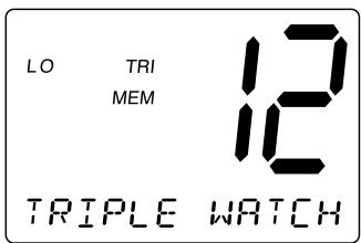
Press and hold 16/9/TRI for 2 seconds to cancel the Triple Watch mode.
Note: While in Triple Watch mode, you can change the currently selected channel using CH ▲ and ▼. A momentary press of the 16/9/TRI button interrupts Triple Watch mode and remains on channel 16, or on channel 9 if you press 16/9/TRI once more. To return to the Triple Watch mode, simply press the button again.
MANUAL TUNING
To manually select a channel, press CH ▲ or ▼. Communication channels are located on channel 01-28 and 60-88.
MEM (Entering channel numbers into Memory Scan)
You can enter channels into Memory Scan for instant scanning at any time. When a channel is selected for Memory Scan, MEM appears on the LCD display.
To enter a channel into Memory Scan, select the channel you want to store by using CH▲ and , and then press MEM. The channel is stored in Memory Scan and MEM appears on the LCD display.
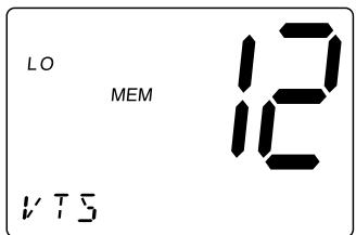
To cancel the channel in Memory, press MEM.
Triple Watch Scan
To turn Triple Watch Scan On, press and hold STEP/SCAN for 2 seconds. While the current channel is scanned, Channel 16 and Channel 9 are also scanned every 2 seconds. Then TRI appears.
Normal Scan
Normal Scan is performed only when the memory CH is registered.
To turn Normal Scan On, press and hold 16/9/TRI for 2 seconds in Triple watch Scan mode. Although Memory CH is scanned, Channel 16 and Channel 9 are not.
TRANSMITTING
Note: Channel 70 is DSC only. All the available marine channel are located on page 49.
SETTING TX OUTPUT
Caution: It is important to remember to use the LO position in port or for short range communications.
- When you turn the radio On for the first time, the unit is automatically set to transmit at 25 watts (HI).
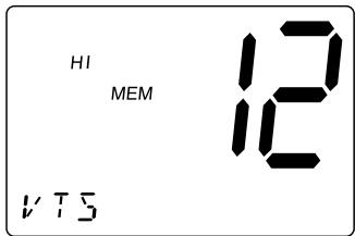
- Press HI/LO to change the transmitter output to 1 watt (LO).
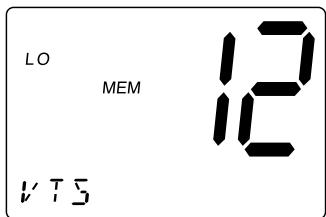
- Press HI/LO again to change back to 25 watts (HI).
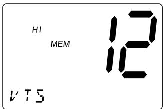
Note: Each time the HI/LO is pressed a short tone sounds. When the channel is set as LO power channel, you can transmit at 25 watts (HI) by pressing and holding HI/LO during the call (except for CH75 and CH76).
DISTRESS
Note: You must set the user MMSI in order to send a Distress call. Please see page 42 to set the MMSI.
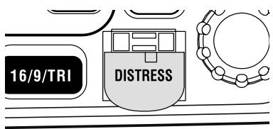
This feature will allow you to transmit a Distress call.
- Press QUICKLY DISTRESS.
UNDESIGNATED appears and starts blinking. You can skip steps 1 and 2 WHEN IMMEDIATE HELP IS NEEDED.
- Select the type of distress you desire by using CH ▲ and ∇ (fire, flooding, collision, etc.). You may skip this step if you cannot specified the type in a hurried situation.
- Press and hold DISTRESS for 3 seconds. The radio starts counting down. NEVER USE THE DISTRESS CALL WHEN YOUR SHIP OR PERSON IS NOT IN AN EMERGENCY.
- Upon elapse of the 3 second countdown period, the selected distress call is transmitted with high power.
Note: TX appears when a Distress call is transmitted. Make sure the Distress call has been transmitted by checking the status of TX.
- The Distress call is transmitted and it waits for about 210 - 270 seconds. This is continued internally.
After the Distress call has been sent, the Distress alert will sound every other second, and it also "shadow-watches" for a transmission between CH16 and CH70
until an acknowledgment signal is received from the Coast Guard shore station.
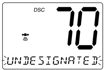
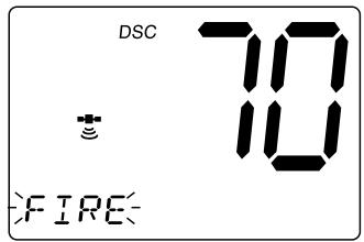
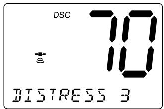
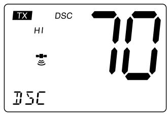
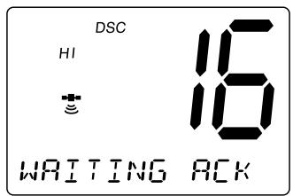
To cancel the Distress call, press 16/9/TRI.
- When the radio receives a Distress call, the following screen appears. If an acknowledgment is not received, the Distress call is repeated until an acknowledgment is received from the Coast Guard shore station.
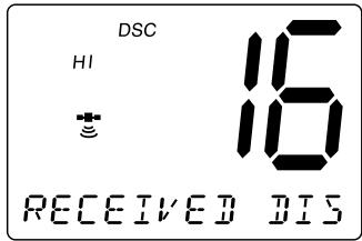
Notes: If you press and hold DISTRESS for 3 seconds instead of just pressing DISTRESS at step 1, the radio will transmit a Distress call with UNDESIGNATED as the default setting.
- If the radio receives a Distress call, it will be displayed on the LCD display. An emergency alert will sound. The name will be displayed if it is the name registered in the directory. Otherwise, sender's MMSI is displayed. Latitude, longitude, and time information will also be displayed if the GPS module is carried in the vessel that transmitted a DSC Distress call.
MARINE DISTRESS PROCEDURE
Speak slowly - clearly - calmly.
- Make sure your radio is On.
- Tune to Channel 16.
- Press the PTT button on the microphone and say: "MAYDAY - MAYDAY - MAYDAY."
- Give your ship ID.
- Say "MAYDAY [your ship name]."
- Give your location: (what navigational aids or landmarks are near).
- State the nature of your distress.
- Give the number of persons aboard and the conditions of any injured.
- Estimate present seaworthiness of your vessel.
- Give a brief description of your vessel (meters, type, color, hull).
- Say: "I will be listening on Channel 16".
- End message by saying "THIS IS [your ship name or call sign] OVER."
- Release the PTT button and listen. Someone should answer. If not, repeat call, beginning at Item 3 above.
Menu Operation
1. DIGITAL SELECTIVE CALLING (DSC)
Digital Selective Calling is a process of establishing a radio call, it has been chosen by the International Maritime Organization (IMO) as an international standard for establishing VHF, MF and HF radio calls. Digital Selective Calling has also been selected as part of the Global Maritime Distress and Safety System (GMDSS).
This service will let you instantly send a Distress call with GPS position (when optional GPS receiver is connected to the RT-2500) to the Coast Guard and other vessels within range of the transmission.
DSC will also let you initiate or receive distress, urgency, safety, position information and routine calls to or from another vessel outfitted with a DSC transceiver.
See the directory section for instructions on how to setup the directory of names.
Note: • Position SEND and ALARM CLOCK will not be displayed if GPS is not connected.
Refer to page 7 for the flow chart of Menu Operation.
- Press MENU to enter Menu Operation.
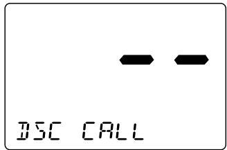
- Press SELECT to enter DSC CALL.
DSC CALL has 7 options as follows.
To exit, select EXIT.
1-A. INDIVIDUAL
- Press SELECT at DSC CALL.
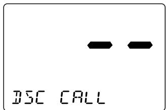
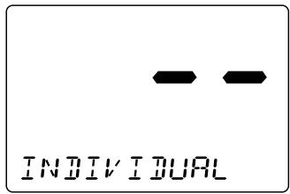
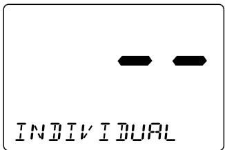
- INDIVIDUAL appears.
Press SELECT.
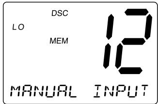
- Select MANUAL INPUT or individual you want to contact using CH ▲ and ▼, then press SELECT.
When you select MANUAL INPUT, you can contact the person who is not registered in the directly. Using the number key pad on the mic, enter the ID. Press CH ▲ to move the cursor to the right, and CH▼ to the left. When you finish entering the last digit, press SELECT.
- Select a response channel using CH ▲ and ▼. Press SELECT to transmit the individual call.
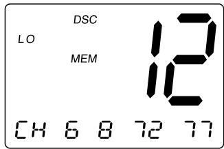
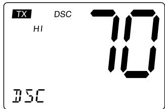
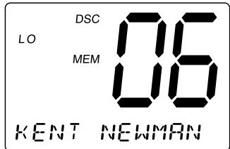
- When you receive the individual acknowledgment successfully, COMPLETED appears. Both radios tune to the selected channel. You are now ready to transmit on that channel.
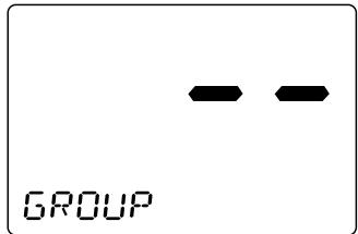
1-B. GROUP
- Press SELECT at DSC CALL (To enter DSC CALL, see page 18). INDIVIDUAL appears.
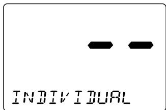
- Press CH▼ once to select GROUP.
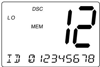
- Press SELECT. The MMSI code appears.
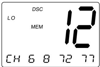
- Press SELECT and select a response channel using CH ▲ and ▼.
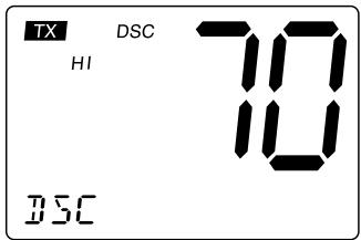
- Press SELECT to transmit the group call.
1-C. ALL SHIPS
- Press SELECT at DSC CALL (To enter DSC CALL, see page 18). INDIVIDUAL appears.
- Press CH twice to select ALL SHIPS.
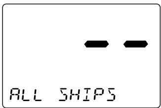
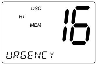
- Press SELECT. URGENCY appears.
-
Select the category of your call using CH ▲ and ▼ (URGENCY, SAFETY, EXIT).
-
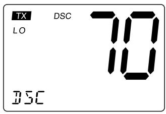
Press SELECT to transmit the ALL SHIPS DSC signal. When sending either an URGENCY or SAFETY message, all radios will automatically move to channel 70 until all of the data is received.
-
After selecting URGENCY or SAFETY ALL SHIPS call is transmitted, the radio will switch to Channel 16. You should wait a few minutes before transmitting the ALL SHIPS call information.
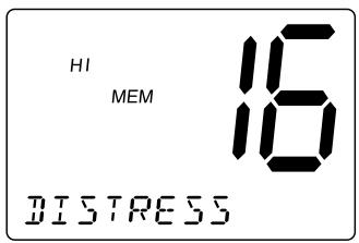
1-D. POSITION REQUEST
This radio has the ability to request the position of an individual vessel that is registered in the DIRECTORY.
- Press SELECT at DSC CALL (To enter DSC CALL, see page 18). INDIVIDUAL appears.
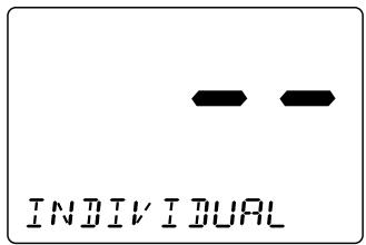
- Display POS REQUEST using CH▲ and CH▼, then press SELECT.
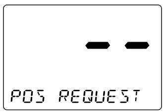
- Select the MANUAL INPUT or individual you want to request the position using CH ▲ and ▼, then press SELECT. When you select MANUAL INPUT, you can contact the person who is not registered in the directly. Using the number key pad on the mic, enter the ID. Press CH ▲ to move the cursor to the right, and CH ▼ to the left.
- When you finish entering the last digit, press SELECT to transmit the position request call.
- When the called vessel sends the position information, time and position appears followed by the individual. You can see the time and the position.
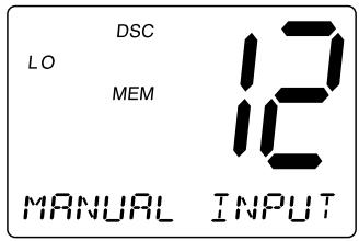
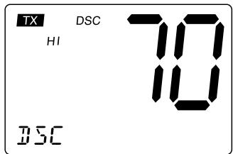
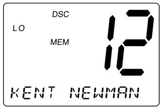
Note: The requested radio must have the ability to transmit the position information (such as having a RT-2500 radio).
1-E. POSITION SEND
This radio has the ability to send the position of your vessel to another vessel using a VHF marine radio equipped with DSC.
Note: Position send is only available when it is connected to the GPS.
- Press SELECT at DSC CALL (To enter DSC CALL, see page 18). INDIVIDUAL appears.
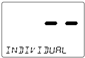
- Display POS SEND using CH▲ and CH▼, then press SELECT.
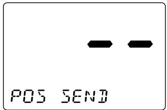
- Select MANUAL INPUT or individual you want to send your position information using CH ▲ and ▼, then press SELECT. When you select MANUAL INPUT, you can contact the person who is not registered in the directly. Using the number key pad on the mic, enter the ID. Press CH ▲ to move the cursor to the right, and CH ▼ to the left.
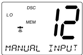
- When you finish entering the last digit, press SELECT to transmit the position send call.
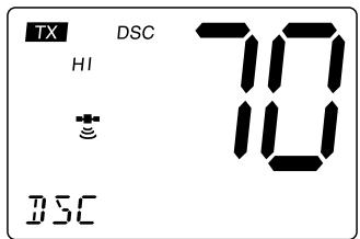
1-F. STANDBY
The DSC STANDBY function allows the RT-2500 to answer DSC calls with the UNATTENDED message and record the calls for response at another time. When you set the radio to DSC STANDBY mode, voice traffic may still be active on any chosen channel.
- Press SELECT at DSC CALL (To enter DSC CALL, see page 18). INDIVIDUAL appears.
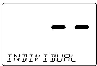
- Display STANDBY using CH▲ and CH▼. Then press SELECT.
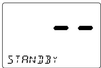
- When an individual DSC call is received, the radio will respond with the UNATTENDED message when an operator cannot answer the call. The DSC call will be recorded into the radio's Call Waiting directory.
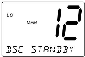
Note: If you press a key on the radio or the PTT, this feature will be canceled.
1-G. CALL WAIT
The DSC Call Waiting directory records 10 received distress calls, and records 20 individual calls that are received and not answered within 5 minutes or while the radio is set to DSC Standby. Calls will be recorded while you are busy with other communications as long as the transmitter is not keyed at the time of the call. If the call is answered within 5 minutes the call will not be recorded. When a call is recorded, a message appears.
- Press SELECT at DSC CALL (To enter DSC CALL, see page 18). INDIVIDUAL appears.
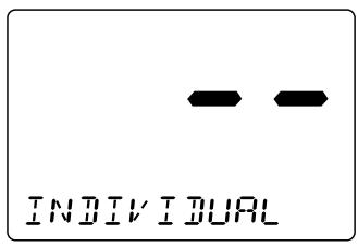
- DisplayCALLWAIT using CH and CHV
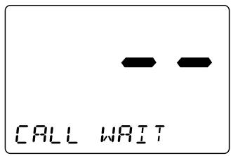
- Press SELECT. The CALL WAIT directory appears.
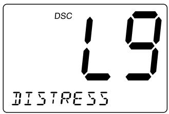
- Select the options you want to view using CH and .
Note: If a call has not been logged, the radio will beep and you will not be able to proceed to the next step.
- Press SELECT.
- If a DISTRESS call is received in Call Wait, the following display appears.

If an INDIVIDUAL call is received in Call Wait, the following display appears. At this point, you can call back any of the radios in the log.
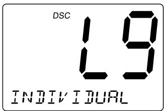
- Press SELECT. Received data appears.
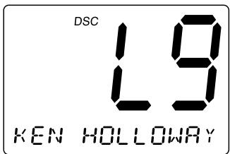
- Using CH and allows you to look through all of the data. If you press SELECT, the radio starts transmitting.
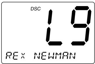
Geographical Call
This function can receive the electric wave transmitted towards the ship that is present in the domain specified from the call side.
Note: The radio receives geographical calls only, and sending geographical calls is not available. It indicates the time when the geographical call is received.
2. SETUP
-
Press MENU to enter Menu Operation.
-
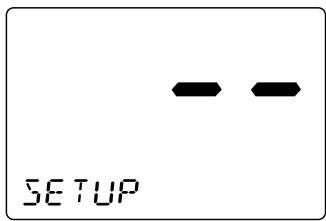
Press CH once to display SETUP, and press SELECT.
SETUP has some options as follows. To exit, select EXIT.
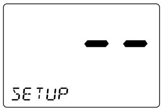
2-A. ALARM CLOCK
This feature is only available when the GPS is connected to the NMEA0183 Accessory Wires. If it is connected to the GPS, the alarms are set based on the satellite. You need to set the time previously to setting the alarm.
2-A-1. ALARM SET
This feature allows you to set the alarm.
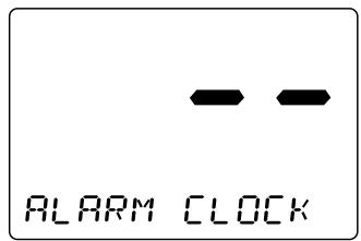
- Press SELECT at SETUP.
FLARM CLOCK appears.
-
Press SELECT.
-
Press CH ▲ or ▼ to select On. Then, press and hold SELECT.
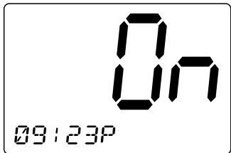
-
Select the hour and minute using the number keypad on the MIC.
-
Select AM or PM using 2 or 7 on the MIC then press SELECT.
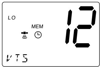
- The radio returns to the channel display screen.
2-A-2. ALARM ON
This feature allows you to turn the alarm ON.
- Press SELECT at SETUP (To enter SETUP, see page 27).
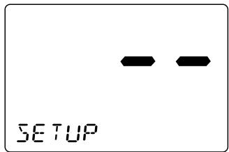
- ALARM CLOCK appears. Then, press SELECT.
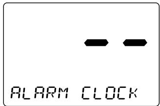
- Select On. Using CH ▲ or ▼, and press SELECT. The radio returns to the channel display screen and the ⊙ icon appears.
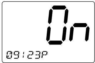
- When the radio reaches the set time the alarm sounds and the icon blinks.
Note: The alarm sounds when the set time is reached, you can turn the alarm Off by pressing any key. Alarm mode will turn Off automatically once the alarm sounds.
2-A-3. ALARM OFF
This feature allows you to turn the alarm OFF.
- Press SELECT at SETUP (To enter SETUP, see page 27).
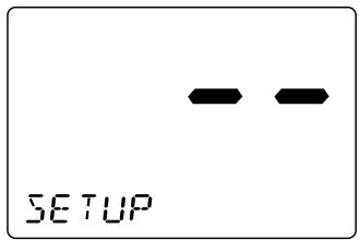
- ALARM CLOCK appears.
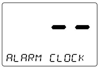
-
Press SELECT.
-
Select using CH or , then press SELECT.
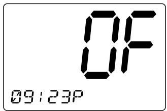
- The radio returns to the channel display screen and the icon disappears.
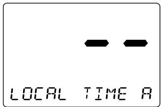
2-B. LOCAL TIME ADJUST
This feature allows you to fine tune the Local Time for any location in Europe. The feature enables you to adjust the Local time by ± 1 hour.
To set LOCAL TIME ADJUST
- Press SELECT at SETUP (To enter SETUP, see page 27).
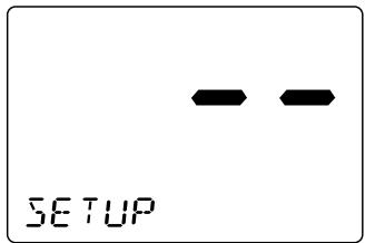
- Display LOCAL TIME ADJUST using CH▲ and CH▼.
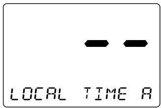
- Press SELECT. The registering screen appears. You can now adjust the time for your local area using CH▲ and CH▼.
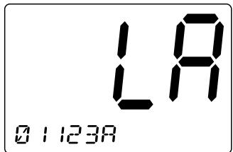
- The time will be entered when you press SELECT. The display returns to LOCAL TIME ADJUST screen.
2-C. DAYLIGHT SAVINGS On/Off
This feature enables you to select the automatic Daylight Savings clock setting.
To set DAYLIGHT SAVINGS On/Off
- Press SELECT at SETUP (To enter SETUP, see page 27).
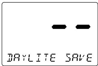
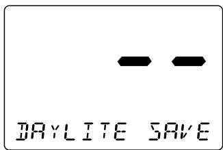
- Display DAYLITE SAVE using CH▲ and CH▼.
- Press SELECT. Then press CH▲ to set DAYLIGHT SAVINGS on or CH▼ to off (the default setting is off).
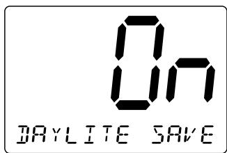
- Press SELECT. The display returns to DAYLITE SAVE screen.
2-D. DIRECTORY
This function will allow you to send an individual call, etc. The Directory function memorizes the name and MMSI number of 20 other vessels. The following screen will allow you to setup an alphanumeric identity as well as the corresponding MMSI number.
- Press SELECT at SETUP (To enter SETUP, see page 27).
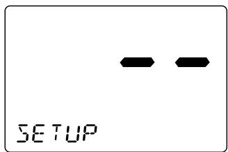
- Display DIRECTION using CH ▲ or ▼.
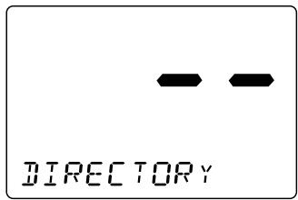
- Press SELECT. The DIRECTORY menu appears. Use CH ▲ or ▼ to select the menu.
2-D-1. NEW
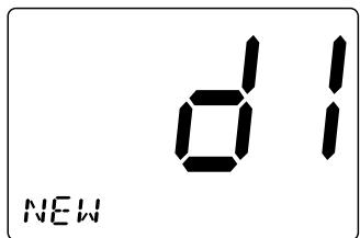
This function will allow you to enter new information into the directory.
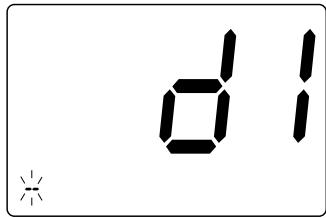
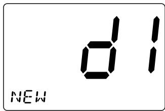
- Press SELECT at NEU. The registering screen appears.
- You can now enter the person's name. Using the number key pad on the mic, choose the alphabet. The character will be entered when SELECT or the differnft number key is pressed, and the blinking digit moves to the right.
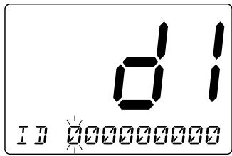
- After you enter the person's name, you can enter their MMSI number. Using the number key pad on the mic, enter their MMSI number. Press CH ▲ to move the cursor to the right, and CH▼ to the left.
- When you finish entering the last digit, press SELECT. the radio returns to New screen.
2-D-2.EDIT
If you want to edit the DIRECTORY
- Press SELECT at the individual you want to edit.
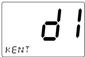
- EDIT appears, then press SELECT.
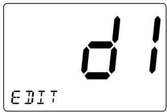
- You can now edit the person's name. Using the number key pad on the mic choose the alphabet.
- After you edit the person's name, you can edit the MMSI. The number will be entered when SELECT or the different number key is pressed, and the blinking digit moves to the right.
- After the directory data is edited, the individual appears.
2-D-3. DELETE
If you want to delete the directory
- Press SELECT at the individual you want to delete.
- Press CH▼ once. DELETE appears, then press SELECT.
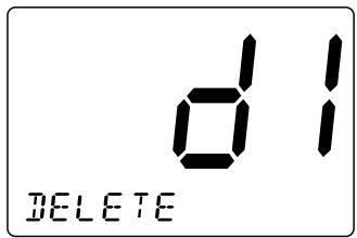
- The radio displays the next individual. If no more code remains, EXIT appears.
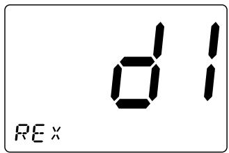
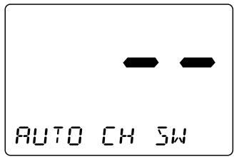
2-E. AUTO CHANNEL SWITCH
This feature is to allow you to disable the automatic channel change that happens when receiving a DSC call. This feature is useful when engaged in bridge - to - bridge or other safety related calls. When you have completed these calls, all of the incoming DSC calls received are available in the call log.
- Press SELECT at SETUP (To enter SETUP, see page 27).
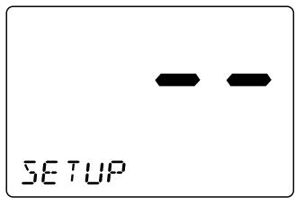
- Display AUTO CH SW using CH ▲ and ▼.
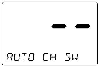
- Press SELECT to enter the setting mode.
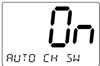
- If you want to change this mode to off, press CH once. (Default is set as ON.)
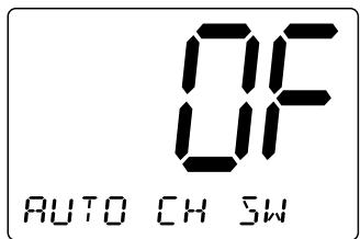
- Press SELECT. The radio returns to the AUTO CH 5U screen.
2-F. POSITION REPLY
When the calling radio has requested the position information of your radio, you can decide to transmit an acknowledgment automatically or on a call by call basis.
- Press SELECT at SETUP (To enter SETUP, see page 27).
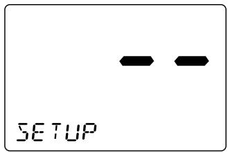
- Display POS REPLY using CH ▲ and ▼.
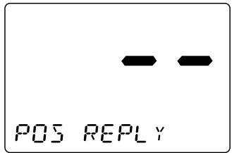
- Press SELECT to enter the setting mode.
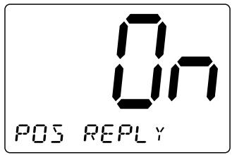
- Press CH ▲ or ▼ to make your selection.
Example: On
When the radio receives a position request, the following screen appears.
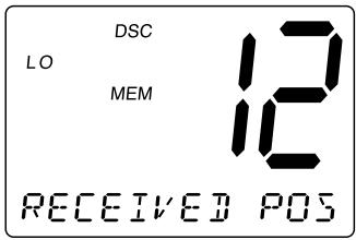
Example: DF
When the radio receives a position request, the following screen appears. You can select whether reply the request or not. If you wants to reply press SELECT.
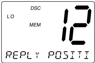
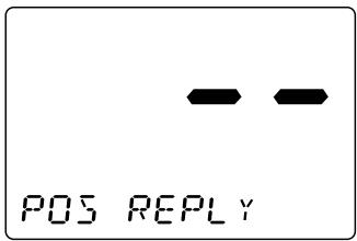
- Press SELECT. The radio returns to the POS REPLY screen.
2-G. CH TAG
This feature allows you to name each marine channel.
- Press SELECT at SETUP (To enter SETUP, see page 27).
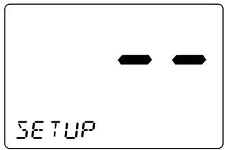
- Display CH TAG using CH ▲ and ▼.
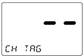
- Press SELECT. The channels and its names appear.
- Press CH ▲ and ▼ repeatedly to select the channel that you would like to EDIT.
Note: The RT-2500 radio comes pre-programmed with default channel names.
2-G-1. EDIT
If you want to edit the channel name
- Press SELECT at the individual channel you want to edit.
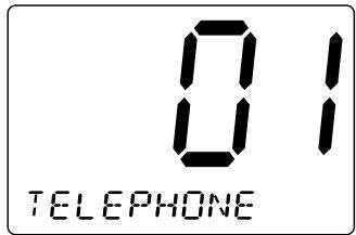
- You can edit the name. Using the number key pad on the mic select the alphabet, numeric, or symbols. The character will be entered when SELECT or the differnft number key is pressed, and the blinking digit moves to the right.
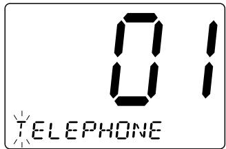
- Press and hold SELECT when you enter the last digit.
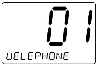
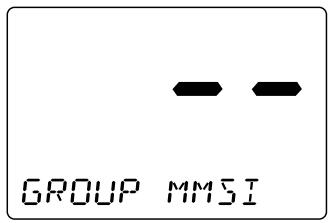
2-H. GROUP MMSI
- Press SELECT at SETUP (To enter SETUP, see page 27).
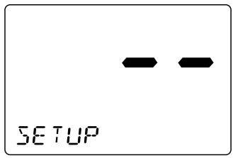
- Display GROUP MMSI using CH ▲ and ▼.
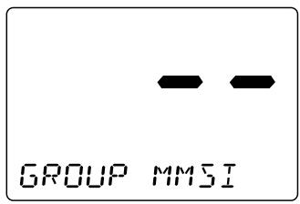
- Press SELECT. The group MMSI ID screen appears.
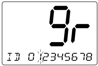
-
You can now enter the GROUP MMSI code. Use the number key pad on the mic to display the number. The number will be entered when SELECT or the different number key is pressed, and the blinking digit moves to the right.
-
After the final digit is entered, a confirmation screen appears. Press SELECT and the radio returns to the following screen.
2-1. USER MMSI
User MMSI are usually issued by the national telecommunications authority of your country. You will need to obtain a nine-digit MMSI number and program it into the RT-2500. In the event of distress, this information together with the GPS-derived position coordinates is useful in search-and-rescue (SAR) operations by rescue organizations, such as the coast guard, marine police and navy. To obtain an MMSI number, contact your authorized Jmc dealer.
This portion of the SETUP menu will allow you to program an MMSI, (Maritime Mobile Service Identity) for sending and receiving DSC calls.
To set USER MMSI code
- Press SELECT knob at SETUP.
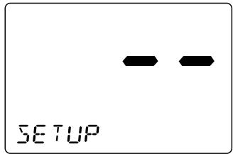
- Press CH eight times to select USER MMSI.
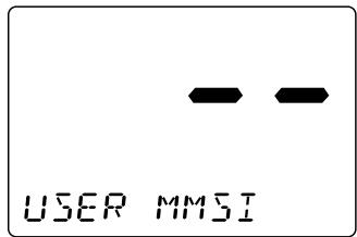
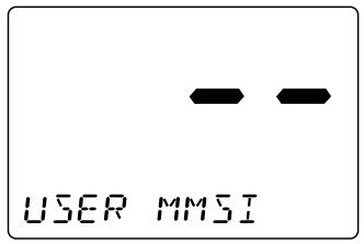
- Press SELECT. The user MMSI ID screen appears.
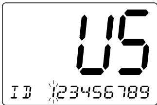
-
You can now enter the USER MMSI code. Use the number key pad on the mic to display the number. The number will be entered when SELECT is pressed, and the blinking moves to the right.
-
After the final digit is entered, press and hold SELECT. The radio returns to USER MMSI screen.
Note: You can only program your radio once with an MMSI number. After that, send your radio to Jmc for factory service.
2-J. ATIS ID
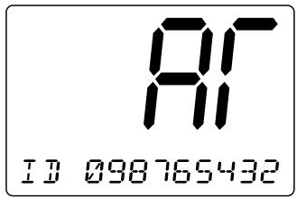
ATIS is the automatic transmitter identification system. The ATIS ID is composed by number of 10 digits, and it is already registered to your radio. The first digit is pre-selected to "9", but it doesn't appear on the display. From 2nd to last digits are displayed.
To confirm the ATIS ID
- Press SELECT knob at SETUP.
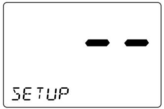
- Press CH▼ nine times to select ATIS ID.
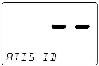
- Press SELECT. The ATIS ID number appears.
3. SYSTEM
-
Press MENU to enter Menu Operation.
-
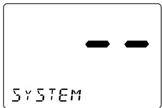
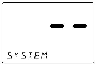
Press CH twice to display SYSTEM, and press SELECT.
SYSTEM has 3 options as follows. To exit, select EXIT.
3-A. CONTRAST
- Press SELECT at SYSTEM. CONTRAST appears.
- Press SELECT to enter the setting mode. (Default is set at 7).
- Press CH and to increase or decrease the contrast level.
- When you find the most favorable brightness, press SELECT. The radio returns to the CONTRAST screen. If you want to exit the setting screen without changing the contrast, press MENU.
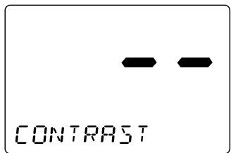
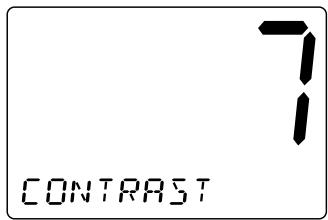
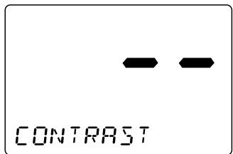
Note: There are 8 contrast levels (0 - 7).
3-B. LAMP ADJUST
- Press SELECT at SYSTEM. (To enter SYSTEM, see page 44.)
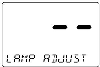
- Press CH once to select LAMP ADJUST.
- Press SELECT to enter the setting mode. (Default is set at 3).
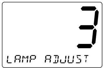
- Press CH and to select the backlight brightness level.
- When you find the most favorable brightness, press the SELECT. The radio returns to the LAMP ADJUST screen.
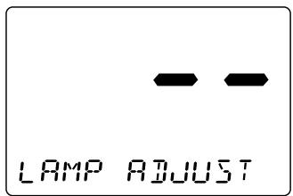
Note: The backlight settings are off, Level 1 Dim, Level 2 medium, and Level 3 bright.
3-C. KEY BEEP
- Press SELECT at SYSTEM. (To enter SYSTEM, see page 44.)

- Press CH▼ twice to select KEY BEEP.
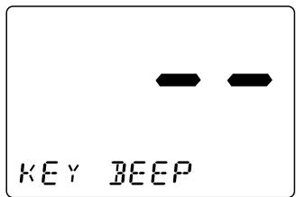
- Press SELECT to enter the setting mode.
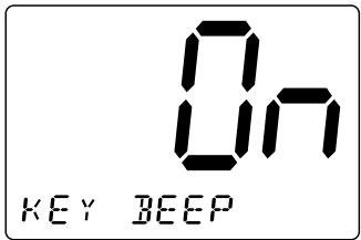
-
Press CH ▲ or ▼ to select ON or OFF.
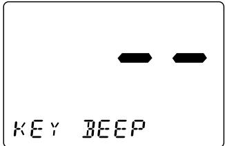
-
Press SELECT. The radio returns to the KEY BEEP screen.
Switching the Inland Waterway Mode/Seagoing Mode
You can switch between Inland Waterway mode and Seagoing mode. Press and hold PA/MODE for 5 seconds to switch between the two.
When the radio in the Inland Waterway mode; DISTRESS/DSC cannot be transmitted nor received. Only ATIS can be transmitted. WX blinks.
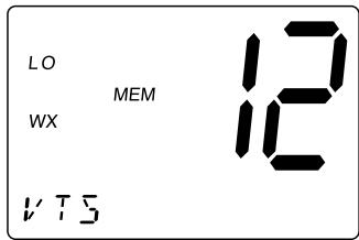
When the radio in the Seagoing mode; Transmission and reception of DISTRESS/DSC, and transmission of ATIS can be available.
Displaying GPS information
If the GPS module is properly connected to the radio and is working, press SELECT to display the current GPS information, date, time, latitude, and longitude. Press SELECT again to set the radio to its marine mode.
Setting Position for Distress Call
To set the radio to its position setting mode, press SELECT when the radio is set to its marine mode and does not have a GPS module connected. A screen appears that you can use to set the UTC time, latitude, and longitude used with Distress call.
Example:
Push 08231034 SELECT, 1234567(S) SELECT, 13579246(E) SELECT of MIC when you set day, time, the position like "08/23 10:34 12° 34.567S and 135° 79.246E". (3: East, 6: North, 7: South, 9: West)
NMEA Technical Setup
OCEANUS NMEA0183 GPS Input Connection Specification
This section is useful when attaching an external GPS to the RT-2500 radio. Many GPS units have a setup menu to be able to configure the NMEA0183 serial data output. This output can be used to supply information to other devices on the vessel, such as the RT-2500 VHF radio, auto pilots, chart plotters, etc.
To setup the GPS to be used with the RT-2500 radio, the following items need to be considered for proper operation:
- Baud Rate – Set the Baud rate to 4800.
- Data Bits - Set the Data Bits to 8.
- Parity - Set the Parity to None.
- Stop Bits - Set the Stop Bits to 1.
- GPRMC Command – This command is used by the RT-2500 and includes the UTC Time, Latitude, Longitude, Speed, Direction, and Date information.
The data amplitude : Over 3.0V
Drive capability : Over 10mA
Optional Accessories
- Flush mounting bracket for "in dash" installation.
(Black = FMB322B)
Contact your Dealer for information.
VHF FM Marine Radio Telephone Channel and Functions
(International Channels)
| CHANNEL DESIG | FREQUENCY (MHz) | TYPE OF TRAFFIC | SHIP TO SHIP | SHIP TO SHORE | CH TAG | |
| TRANSMIT | RECEIVE | |||||
| 01 | 156.050 | 160.650 | VTS, Duplex | Yes | Yes | TELEPHONE |
| 02 | 156.100 | 160.700 | Port Ops, Duplex | Yes | Yes | TELEPHONE |
| 03 | 156.150 | 160.750 | Port Ops, Duplex | Yes | Yes | TELEPHONE |
| 04 | 156.200 | 160.800 | Port Ops, Duplex | Yes | Yes | INTL |
| 05 | 156.250 | 160.850 | VTS, Duplex | Yes | Yes | INTL |
| 06 | 156.300 | 156.300 | Safety | Yes | No | SAFETY |
| 07 | 156.350 | 160.950 | Com', DuplexI | Yes | Yes | INTL |
| 08 | 156.400 | 156.400 | Com'I | Yes | No | COMMERCIAL |
| 09 | 156.450 | 156.450 | Com'I & Non Com'I | Yes | Yes | CALLING |
| 10 | 156.500 | 156.500 | Com'I | Yes | Yes | COMMERCIAL |
| 11 | 156.550 | 156.550 | Com'I | Yes | Yes | VTS |
| 12 | 156.600 | 156.600 | Port Ops | Yes | Yes | VTS |
| 13 | 156.650 | 156.650 | Navigational | Yes | Yes | BRG/BRG |
| 14 | 156.700 | 156.700 | Port Ops | Yes | Yes | VTS |
| 15 | 156.750 | 156.750 | Environmental | Yes | Yes | COMMERCIAL |
| 16 | 156.800 | 156.800 | Safety Calling | Yes | Yes | DISTRESS |
| 17 | 156.850 | 156.850 | State Control | Yes | Yes | SAR |
| 18 | 156.900 | 161.500 | Com'I, Duplex | Yes | Yes | INTL |
| 19 | 156.950 | 161.550 | Com'I, Duplex | Yes | Yes | INTL |
| 20 | 157.000 | 161.600 | Port Ops, Duplex | Yes | Yes | PORT OPR |
| 21 | 157.050 | 161.650 | Coast Guard, Duplex | Yes | Yes | INTL |
| 22 | 157.100 | 161.700 | Coast Guard, Duplex | Yes | Yes | INTL |
| 23 | 157.150 | 161.750 | Coast Guard, Duplex | Yes | Yes | INTL |
| 24 | 157.200 | 161.800 | Public Corresp, Duplex | No | Yes | TELEPHONE |
| 25 | 157.250 | 161.850 | Public Corresp, Duplex | No | Yes | TELEPHONE |
| 26 | 157.300 | 161.900 | Public Corresp, Duplex | No | Yes | TELEPHONE |
| 27 | 157.350 | 161.950 | Public Corresp, Duplex | No | Yes | TELEPHONE |
| 28 | 157.400 | 162.000 | Public Corresp, Duplex | No | Yes | TELEPHONE |
| 60 | 156.025 | 160.625 | Duplex | TELEPHONE | ||
| 61 | 156.075 | 160.675 | Duplex | INTL | ||
| 62 | 156.125 | 160.725 | Duplex | INTL | ||
| 63 | 156.175 | 160.775 | Duplex | INTL | ||
| 64 | 156.225 | 160.825 | Duplex | TELEPHONE | ||
| 65 | 156.275 | 160.875 | Port Ops, Duplex | Yes | INTL | |
| 66 | 156.325 | 160.925 | Port Ops, Duplex | Yes | Yes | INTL |
| 67 | 156.375 | 156.375 | Com'I | Yes | No | BRG/BRG |
| 68 | 156.425 | 156.425 | Non Com'I | Yes | Yes | SHIP-SHIP |
| 69 | 156.475 | 156.475 | Non Com'I | Yes | Yes | PLEASURE |
| 70 | 156.525 | 156.525 | DSC | |||
| 71 | 156.575 | 156.575 | Non Com'I | Yes | Yes | PLEASURE |
| 72 | 156.625 | 156.625 | Non Com'I | Yes | No | SHIP-SHIP |
| 73 | 156.675 | 156.675 | Port Ops | Yes | Yes | PORT OPR |
| 74 | 156.725 | 156.725 | Port Ops | Yes | Yes | PORT OPR |
| 75 | 156.775 | 156.775 | ||||
| 76 | 156.825 | 156.825 | ||||
| 77 | 156.875 | 156.875 | Port Ops | Yes | No | PORT OPR |
| 78 | 156.925 | 161.525 | Non Com'I, Duplex | Yes | Yes | INTL |
| 79 | 156.975 | 161.575 | Com'I, Duplex | Yes | Yes | INTL |
| 80 | 157.025 | 161.625 | Com'I, Duplex | Yes | Yes | INTL |
| 81 | 157.075 | 161.675 | Coast Guard, Duplex | Yes | Yes | INTL |
| 82 | 157.125 | 161.725 | US Govt Only, Duplex | Yes | Yes | INTL |
| 83 | 157.175 | 161.775 | Coast Guard, Duplex | Yes | Yes | INTL |
| 84 | 157.225 | 161.825 | Public Corresp, Duplex | No | Yes | TELEPHONE |
| 85 | 157.275 | 161.875 | Public Corresp, Duplex | No | Yes | TELEPHONE |
| 86 | 157.325 | 161.925 | Public Corresp, Duplex | No | Yes | TELEPHONE |
| 87 | 157.375 | 157.375 | Public Corresp, Duplex | No | Yes | TELEPHONE |
| 88 | 157.425 | 157.425 | Com'I, Duplex | Yes | No | TELEPHONE |
Specification
General
Controls
Status Indicators
: On-Off/Volume, Squelch
: TX (Transmit), TRI (Triple Watch), HI (High), LO (Low), U, C, I, MEM, WX, DSC, (Alarm), 三 (GPS), (WHAM), and Channel Display
: LCD with Orange backlight
: 16/9/TRI, DISTRESS, PA/MODE, MEM, SELECT, STEP/SCAN, MENU, HI/LO
: Antenna, Remote, ACC, and DC power
: H63 mm x W160 mm x L168 mm (W/O Heat Sink) H3.07 inches x W7.24 inches x L6.61 inches
: 1.0 kg / 2.65 lbs / 42.3 oz
: 13.8V DC negative ground
: Mounting bracket and hardware, DC power cord, microphone hanger, spare fuse, ACC Cable
: 50 Ω nominal
Rugged 2k condenser mic element with coiled cord
: 1.82 inch, Mylar Cone 8 Ω
: -15 °C to + 55 °C (+5 °F to +131 °F)
: Meets or exceeds EIA standards, RS152B and RS204C
Transmitter
Power Output
Power Requirement
Modulation
Hum and Noise Signal-to-Noise
Audio Distortion
Spurious Suppression
Output Power Stabilization
Frequency Range
Frequency Stability
: 1 watt or 25 watt (switch selectable)
: Not rated on LO, 25 watts output: 5.6A@13.8V DC
: FM ±5 kHz deviation
: 45 dB@1 kHz with 3 kHz deviation with 1000 Hz modulating frequency (nominal)
Less than 8% with 3 kHz deviation with 1000 Hz modulating frequency
: -70 dBm @ Hi, -70 dBm @ Lo
Built-in automatic level control (ALC)
: 156 to 158 MHz
: ±10 ppm @ -15°C to + 55°C
Receiver
Frequency Range
Sensitivity
Circuit
Squelch Sensitivity
Spurious Response
Adjacent Channel Selectivity
Audio Output Power
Power Requirement
IF Frequencies
: 156 to 163 MHz
: 0.25 V for 12 dB SINAD
: Dual Conversion Super Heterodyne PLL
: 0.8 V Threshold
:70dB
: 75 dB @ ±25 kHz
: 2.8 watts (10% Distortion)
: 200 mA @ 13.8V DC squelched, 0.7A @ 13.8V DC at maximum audio output
: 1st 21.4 MHz, 2nd -455 kHz
Troubleshooting
If the RT-2500 does not perform to your expectations, try the suggestions listed below.
| SYMPTOM | CAUSE | REMEDY |
| Won't power On. | No or low voltage. | Check for proper voltage getting to the set. |
| When the PTT is pressed - TX icon comes on but another radio can hear a “click” but no audio is heard. | Bad mic element. | Send entire unit including mic to your dealer for repairs. |
| While scanning, the radio stops on a particular channel all of the time. | A source of noise is nearby. | Eliminate the source of the noise or delete the channel from the scanner. |
| There is noise on the receiver that the squelch will not eliminate. | An external noise is being generated by some device. | Either turn off the offending device or contact its maker for possible assistance. |
If none of the above suggestions solves your problem, contact your dealer for assistance.
Care and Maintenance
Your RT-2500 is a precision of electronic equipment and you should treat it accordingly. Due to the rugged design, very little maintenance is required. However, a few precautions should be observed:
- If the antenna has been damaged, you should not transmit except in the case of an emergency. A defective antenna may cause damage to your radio.
- You are urged to arrange for periodic performance checks with your Jmc Marine dealer.
EC Declaration of Conformity
We, the undersigned,
| Manufacturer | Japan Marina Company Limited |
| Address | 36-2-1001 Udagawacho, Shibuya-ku, Tokyo |
| Country | Japan |
| Phone number | +81-3-3461-3606 |
| Fax number | +81-3-3496-2078 |
| sales@japan-marina.co.jp |
declare under our sole responsibility that the following apparatus:
| Description | Class-D VHF Marine Radio (for non-SOLAS vessels) | ||
| Manufacturer | Japan Marina Company Limited | ||
| Brand | JMC | ||
| Identification | RT-2500 | ||
| Restrictive use | Protective equipment under IEC 60945-2002, IPX 7 | ||
conforms with the essential requirements of the RTTE Directive 1999/105/EC, based on the following specifications applied:
| Standards |
| EN 300 698-2 V1.1.1 (2000-08), EN 300 698-3 V1.1.1 (2001-05), EN 301 025-2 V.1.1.1 (2000-08), EN 301 025-3 V.1.1.1 (2001-05), EN 301 843-1 V1.2.1 (2004-06), EN 301 843-2 V1.2.1 (2005-06), EN 60945, EN 60950 |
| Conformity certified by Notified Body TNO Certification B.V. (CE0336) |
and therefore complies with the essential requirements and provisions of the RTTE Directive.
| Name and position of person binding the manufacturer or his authorised representative | Hideaki Yoshihara, President |
| Signature | Date |
| 19th October, 2005 |


- Summary Operating Manual
- for
- Model RT-2500
- Fixed Type VHF Marine with DSC, Submersible & 15 Key Microphone
- Contents
- Setup 27
- System 44
- Switching the Inland Waterway Mode/Seagoing Mode 47
- VHF FM Marine Radio Telephone Channel and Functions (International Channels) 49
- Included with your RT-2500
- Front panel/Microphone
- Flow Chart for Menu Operation
- Installation
- Choosing a Location
- Engine Noise Suppression
- Antenna Considerations
- Antenna Selection and Installation
- Installing the RT-2500
- Operation
- POWER On/Off
- Last Channel Memory
- SQUELCH
- COAST GUARD CHANNEL 16/CHANNEL 9 COMMUNICATIONS
- TRIPLE WATCH
- MANUAL TUNING
- MEM (Entering channel numbers into Memory Scan)
- Triple Watch Scan
- Normal Scan
- TRANSMITTING
- SETTING TX OUTPUT
- DISTRESS
- MARINE DISTRESS PROCEDURE
- Menu Operation
- DIGITAL SELECTIVE CALLING (DSC)
- 1-A. INDIVIDUAL
- 1-B. GROUP
- 1-C. ALL SHIPS
- 1-D. POSITION REQUEST
- 1-E. POSITION SEND
- 1-F. STANDBY
- 1-G. CALL WAIT
- Geographical Call
- SETUP
- 2-A. ALARM CLOCK
- 2-A-1. ALARM SET
- 2-A-2. ALARM ON
- 2-A-3. ALARM OFF
- 2-B. LOCAL TIME ADJUST
- To set LOCAL TIME ADJUST
- 2-C. DAYLIGHT SAVINGS On/Off
- To set DAYLIGHT SAVINGS On/Off
- 2-D. DIRECTORY
- 2-D-1. NEW
- 2-D-2.EDIT
- If you want to edit the DIRECTORY
- 2-D-3. DELETE
- If you want to delete the directory
- 2-E. AUTO CHANNEL SWITCH
- 2-F. POSITION REPLY
- Example: On
- Example: DF
- 2-G. CH TAG
- 2-G-1. EDIT
- If you want to edit the channel name
- 2-H. GROUP MMSI
- 2-1. USER MMSI
- To set USER MMSI code
- 2-J. ATIS ID
- To confirm the ATIS ID
- SYSTEM
- 3-A. CONTRAST
- 3-B. LAMP ADJUST
- 3-C. KEY BEEP
- Switching the Inland Waterway Mode/Seagoing Mode
- Displaying GPS information
- Setting Position for Distress Call
- Example:
- NMEA Technical Setup
- OCEANUS NMEA0183 GPS Input Connection Specification
- Optional Accessories
- VHF FM Marine Radio Telephone Channel and Functions
- Specification
- General
- Transmitter
- Receiver
- Troubleshooting
- Care and Maintenance
- EC Declaration of Conformity
Marque : RADIOLA
Modèle : JMC RT-2500
Catégorie : Radio VHF marine fixe