Bender Pipeline Washer - Coburn - Notice d'utilisation et mode d'emploi gratuit
Retrouvez gratuitement la notice de l'appareil Bender Pipeline Washer Coburn au format PDF.


Questions des utilisateurs sur Bender Pipeline Washer Coburn
0 question sur cet appareil. Repondez a celles que vous connaissez ou posez la votre.
Poser une nouvelle question sur cet appareil
Téléchargez la notice de votre au format PDF gratuitement ! Retrouvez votre notice Bender Pipeline Washer - Coburn et reprennez votre appareil électronique en main. Sur cette page sont publiés tous les documents nécessaires à l'utilisation de votre appareil Bender Pipeline Washer de la marque Coburn.
MODE D'EMPLOI Bender Pipeline Washer Coburn

8500 PIPELINE WASHER

THE ABLILITY TO CLEAN MILKING SYSTEMS BOTH RELIABLY AND ECONOMICALLY HAS MADE THE 8500 PIPELINE WASHER THE BENCHMARK OF THE INDUSTRY.

8500 PIPELINE WASHER INSTALLATION
- Install plumbing for hot and cold water lines, with garden hose shut-off valves on each line within 3' of where the control unit will be installed. (Two 4' inlet hoses are provided.)
WARNING: All input water supply lines require ANTI-BACKFLOW VALVES to prevent chemicals from entering the water supply.
- Install the control unit on the wall
A. If possible do not install above the wash vat.
B. If the unit is installed over 7' from the input plate, longer water input hoses must be provided - 25' provided for 3 input hoses.
- Install input plate on the wash vat. See page 26.
A. 10' of 1/4" O.D. rigid tubing has been provided for the pressure switch line. - Route the 1/4" O.D. rigid tubing between the flexible tubing on the pressure switch and the rubber bushing, on the input plate. Tubing should be sloped for self-draining so condensation does not accumulate.
- Attach the 1/2" I.D. pressure switch tubing to the input plate. Tubing should be cut off 6" below the required level of water in the wash vat.
- Water input to wash vat.
A. From hot solenoid to a 9/16" nipple in the plate on the wash vat.
B. From detergent jar (rear) to a 9/16" nipple in the plate on the wash vat.
C. From acid jar (rear) to a 9/16" nipple in the plate on the wash vat.
D. Use plastic ties to route hoses neatly and insure self-draining.
- Attach the 4' long pressure hoses.
A. Hot on left side.
B. Cold on right side.
TURN FAUCETS ON.
- Wiring the control box: All wiring on installation should be done according to National Electrical Code and Local Regulations. Be absolutely certain this unit is grounded to an approved ground.
POWER INPUT: 115 VAC 60 HZ. SINGLE PHASE. Input terminal L1, N for Neutral and Ground. See page 20 for external wiring diagram.
ADJUSTMENTS
FIRST RINSE AND WASH--See 9750 sequence control rinse and wash notes for ADJUSTMENT procedure. Page 49.

8500 WIRING

115 VAC 60 HZ SINGLE PHASE 3 WIRE. ALL OUTPUT LOADS GREATER
BE ABSOLUTELY CERTAIN THIS UNIT IS
GROUNDED TO AN APPROVED GROUND. THAN 1 AMP. REQUIRE A 115 VAC
CONTACTOR INTERFACE.
ALL WIRING ON INSTALLATION SHOULD BE
DONE ACCORDING TO NATIONAL ELECTRICAL
CODE AND LOCAL REGULATIONS.
③ FOR WARM SANITIZE: CONNECT THE
BLACK/PURPLE WIRE TO A CAPPED
BLACK WIRE. NEXT TO A BLACK
FOR WARM SANITIZE: CONNECT THE BLACK / PURPLE WIRE TO A CAPPED BLACK WIRE. NEXT TO A BLACK WIRE (labelled HOT) ON THE WHITE TIMER CONNECTOR.

FIRST RINSE AND WASH NOTES:
Washer is wired for a 1 min. RINSE, 3 min. normally open DRAIN, and a 8 min. WASH.
- For a 2 min. rinse, 2 min. normally open drain; Connect the black/white wire in the black timer connector, to the DR terminal on the 16 position terminal block.
- For first rinse valve: Connect to the grey wire in the black timer connector.
- To run milk pump 1 min. at the end of each cycle: Replace the red wire in the MD terminal on the 16 position terminal block, with the red / silver wire in the white timer connector.
- Jar models are wired for liquid detergent. When using Powder detergent, move the black wire (labelled HOT) from the black wire terminal to the black / silver wire terminal on the white timer connector.
ACID RINSE, SANITIZE, DRAIN, AND DIVERTER NOTES:
- For warm acid: Connect the black / orange wire to a capped black wire. Next to a black wire (labelled HOT) on the white timer connector.
- For warm sanitize: Connect the black / purple wire to a capped black wire. Next to a black wire (labelled HOT) on the white timer connector.
- For a normally closed drain control, or diverter valve; Replace the wire in the DR, or DV terminal on the 16 position terminal block, with the blue / black wire in the black timer connector.
- For 1 min. of power at the end of each cycle: Connect to the orange / black wire in the black timer connector.

8540 INSTALLATION
8540 FAILSAFE KIT INSTALLATION
- A. On 9450 timer, remove yellow wire from timer "LITE" to timer "STEP" terminals.
B. On 9750 timer, disconnect the connected red and black wires on the black timer connector. - Mount fail timer to the 8 - 32 nuts behind the main timer bracket, or use hook and loop adhesive tape. Adjust timer to 100 minutes. (This will be correct for most installations.)
- Place fail light in the mounting hole in the timer bracket.
- Wire according to electrical diagram.


8500 PARTS LIST


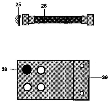
| ITEM | DESCRIPTION | PART NO. |
| 1 | WATER VALVE | 8515 |
| 2 | S.S. HOSE CLAMP - 1/2" | 2392 |
| 3 | CIRCUIT BREAKER - 10 AMP. | 2685 |
| 4 | REINFORCED RUBBER TUBING - 1/2"I.D. X 6 1/2" LONG. | 8519 |
| 5 | PLASTIC NUT - GREEN | 1401 |
| 6 | DETERGENT JAR TOP ASSEMBLY | 8513 |
| 7 | MOUNTING BRACKET | 8816 |
| 8 | LAMP | 8249 |
| 9 | TIMER BRACKET | 8232 |
| 10 | S.S. SCREW - PHILLIPS HEAD 10 - 32 X 3/8" LONG | 6135 |
| 11 | BRACKET | 2682 |
| 12 | TIMER | 9750 |
| TIMER MOTOR - .8 RPM 120VAC / 50-60HZ | 9755 | |
| 13 | SHEET METAL CLIP NUT | 6136 |
| 14 | COIL - 110 VAC | 32551 |
| 15 | PRESSURE SWITCH | 5513 |
| 16 | PLASTIC TUBING - 3/16" I.D. X 1/16" WALL X 8 1/2" LONG. | 8289 |
| 17 | FLEX PLASTIC TUBING - 1/4"O.D. X .060 WALL 10' LONG | 2849 |
| 18 | ACID JAR TOP ASSEMBLY | 8896 |
| 19 | ELBOW - 3/8" NPT X 1/2" HOSE | 8506 |
| 20 | DPDT TOGGLE SWITCH | 6265 |
| 21 | RETENSION WASHER | 2677 |
| 22 | S.S. SCREW - PHILLIPS HEAD 10-32 X 3/8" LONG | 6135 |
| 23 | TERMINAL BOARD | 8886 |
| 24 | DETERGENT AND ACID JAR | 8514 |
| 25 | HOSE GASKET | 1403 |
| 26 | 3/8" I.S. PRESSURE HOSE - 4' LONG | 2541 |
| 27 | S.S. SEAL SCREW - PHILLIPS PAN HEAD 10-24 X 1/2" LONG | 6140 |
| 28 | TIMER KNOB | 8254 |
| 29 | FAIL TIMER - 100 MINUTE | 8926 |
| 30 | S.S. SCREW - PHILLIPS PAN HEAD 8 - 32 X 1.0" LONG | 6159 |
| 31 | GROMMET | 5518 |
| 32 | DIAL INDICATOR | 8234 |
| 33 | CASE ASSEMBLY | 8520 |
| 34 | RUN TEE CHECK VALVE ASSY. - 1/2" HOSE X 3/8" NPT X 1/2" HOSE | 8507 |
| 35 | DETERGENT AND ACID JAR GASKET | 8512 |
| 36 | PLASTIC TUBING - 3/4"I.D. X 1"O.D. X 7-1/2" LONG. | 8835 |
| 37 | PLASTIC TUBING - 1/2" I.D. X 1/8" WALL / FT. | 1099 |
| 38 | PRESSURE SWITCH BUSHING | 2576 |
| 39 | INPUT PLATE | 8505 |
| WATER VALVE REPAIR KIT (not shown) | 7900 |

8500 TROUBLESHOOTING GUIDE
Water valve.
A. Hot on left
-
Front valve to dispense DETERGENT.
-
Rear valve for first rinse and wash fill.
B. Cold on right.
-
Front valve to dispense ACID on second rinse
-
Rear valve for first rinse, second rinse, and sanitize.
VALVE SEQUENCE:
FIRST RINSE = HOT AND COLD
WASH = DETERGENT AND HOT
ACID RINSE = ACID AND COLD
SANITIZE = COLD
PROBLEM
POSSIBLE CAUSE
- Vacuum pump does not start for milking.
a. No voltage on input L1.
b. Circuit breaker tripped.
c. Defective circuit breaker.
d. Defective MILK OFF WASH switch.
e. Defective safety switch.
f. Defective door interlock switch.
- Unable to start the washing cycle.
a. Defective MILK OFF WASH switch.
- No water on any cycle.
a. Defective pressure switch.
- Wash vat overflows on any fill
a. Air leak on pressure switch line. b. Defective pressure switch.
- Water leaking into wash vat.
b. Defective water valve.
- Hot first rinse
a. Defective coil on cold valve. b. Screen plugged on cold valve.
- Cold first rinse
a. Defective coil on hot valve. b. Screen plugged on hot valve.
- No detergent dispensed
a. Defective coil on detergent valve. b. Screen plugged on detergent valve.
- No acid dispensed
a. Defective coil on acid valve. b. Screen plugged on acid valve.

Marque : Coburn
Modèle : Bender Pipeline Washer