AJS1000 Ambic Jet - Matériel agricole Coburn - Notice d'utilisation et mode d'emploi gratuit
Retrouvez gratuitement la notice de l'appareil AJS1000 Ambic Jet Coburn au format PDF.


| Type de produit | Système de pulvérisation de désinfectant pour trayons |
| Marque / Modèle | Coburn AJS1000 Ambic Jet |
| Utilisation principale | Désinfection des trayons des vaches laitières après la traite |
| Alimentation | Ligne de vide régulée du système de traite (pneumatique) |
| Montage / Installation | Fixation murale ; unité de puissance à 3 m maximum au-dessus du réservoir chimique |
| Réservoir de produit chimique | Réservoir séparé (non fourni) ; le tuyau d'aspiration avec filtre repose au fond du réservoir |
| Fonctionnement | Démarrage automatique avec la mise sous vide ; pleine pression atteinte en 1 minute |
| Sécurité | Retour automatique du désinfectant sous pression dans le réservoir à l'arrêt du vide ; protège contre les projections |
| Temps de pulvérisation | Environ 1 seconde par vache |
| Distance de pulvérisation | Buse placée à environ 15 cm sous les trayons ; mouvement circulaire pour une couverture complète |
| Compatibilité des désinfectants | Tous désinfectants de trayons reconnus, à l'exclusion de l'hypochlorite de sodium |
| Entretien du filtre de valve | ATS/444 : remplacer toutes les 1000 heures ou plus tôt si encrassé |
| Entretien de l'insert de purge | ATS/447 : nettoyer toutes les 1000 heures (deux petits orifices à inspecter) |
| Remplacement de la membrane | ATS/443 : remplacer toutes les 3000 heures de fonctionnement |
| Nettoyage du filtre d'aspiration | Rinçage automatique à chaque fin de traite par le retour du désinfectant |
| Pièces détachées disponibles | Vanne directionnelle ATS/425, filtre de valve ATS/444, insert de purge ATS/447, membrane ATS/443, ressort ATS/442 |
| Informations générales | Conçu pour l'environnement d'une salle de traite ; poussiéreux, avec installation proche de la ligne de vide |
| Dimensions (approx.) | 300 × 200 × 150 mm (unité de puissance) |
| Poids (approx.) | 2 kg (unité de puissance) |
| Contenu de la livraison | Unité de puissance, adaptateur de tuyau, tuyaux, tés, pistolets, buses, colliers de serrage, filtres |
FOIRE AUX QUESTIONS - AJS1000 Ambic Jet Coburn
Questions des utilisateurs sur AJS1000 Ambic Jet Coburn
0 question sur cet appareil. Repondez a celles que vous connaissez ou posez la votre.
Poser une nouvelle question sur cet appareil
Téléchargez la notice de votre Matériel agricole au format PDF gratuitement ! Retrouvez votre notice AJS1000 Ambic Jet - Coburn et reprennez votre appareil électronique en main. Sur cette page sont publiés tous les documents nécessaires à l'utilisation de votre appareil AJS1000 Ambic Jet de la marque Coburn.
MODE D'EMPLOI AJS1000 Ambic Jet Coburn
AMBIC™
JETSTREAM
INSTRUCTIONS • ISTRUZIONI • ANLEITUNG • INSTRUCTIES MODE D'EMPLOI • INSTRUCCIONES
A Healthy Herd • A Healthy Profit
1. SCHEMATIC LAYOUT SCHEMA GENERALE
SCHEMATISCHER GRUNDRISS SCHEMATISCH OVERZICHT
SCHEMA SYNOPTIQUE DISPOSICIÓN ESQUEMÁTICA
FIG. 2

AJS/2001
2. INSTALLATION INSTALLAZIONE
INSTALLATION INSTALLATIE
INSTALLATION INSTALACIÓN
FIG. 3

FIG. 4

FIG. 5

FIG. 6

3. MAINTENANCE MANUTENZIONE
INSTANDHALTUNG ONDERHOUD
ENTRETIEN MANTENIMIENTO

- OPERATION USO
FUNKTION BEDIENING
UTILISATION OPERACIÓN

- SPARE PARTS
ELENCO RICAMBI
ERSATZTEILE RESERVEONDERDELEN
PIECES DE RECHANGE REPUESTOS




7. INSTALLATION
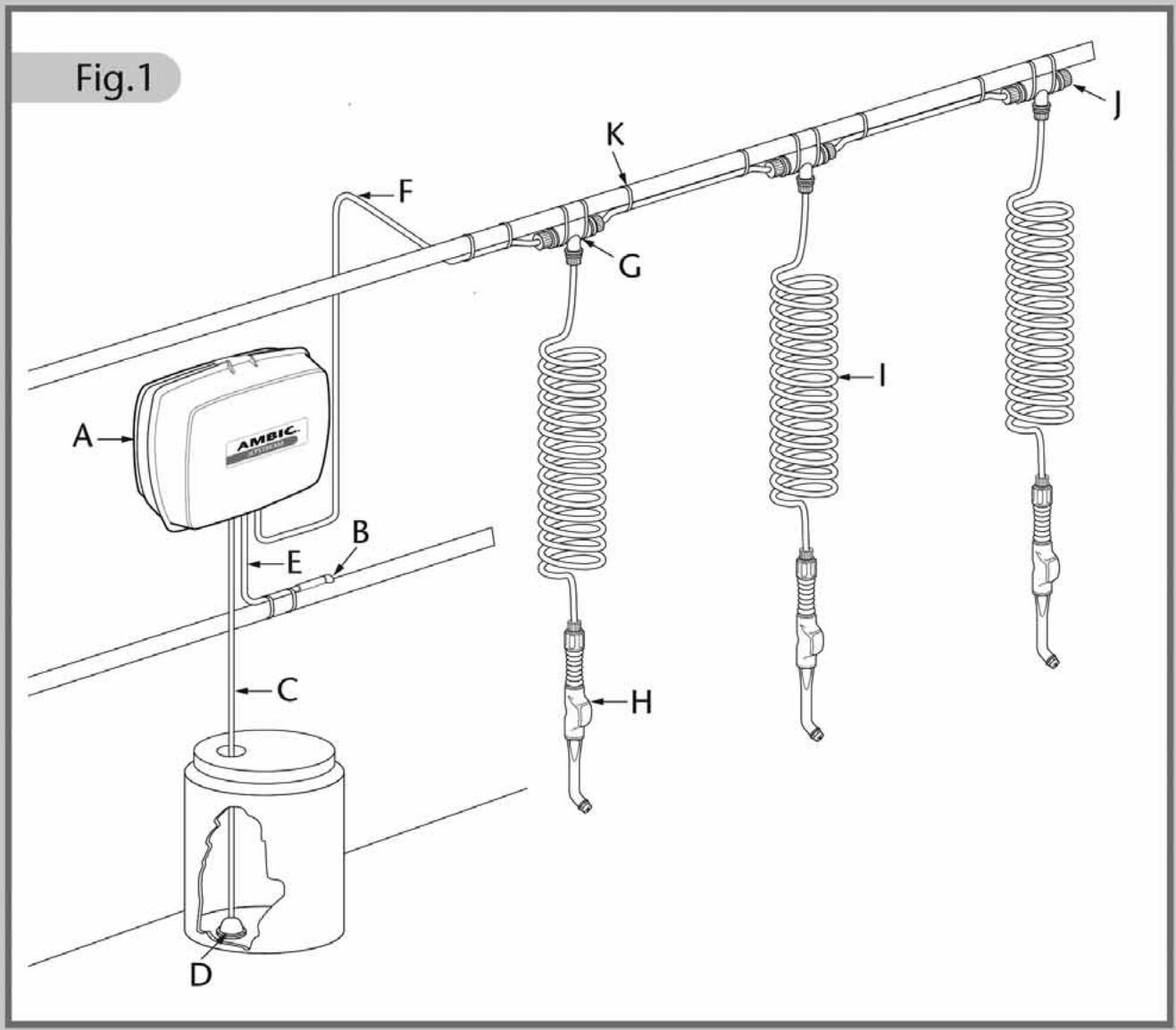
For general parlour layout refer to FIG 1.
Position Power Unit (A) not more than 3 metres (10ft) above the base of the Chemical Container, preferably in a dust free environment, close to a regulated Vacuum Line. The unit will slot onto some existing Wall Brackets. If this is a new system, fix using 2 x screws and rawlplugs. Using the drilling template on page 19, fit one screw first then carefully mark and drill the other. Accuracy between centres is most important.
VACUUM SUPPLY Drill a 10mm∅ (3/8"∅) hole in the top of a regulated main vacuum line (FIG 3). Remove burrs, lubricate Pipe Adaptor (B) and twist into hole.
Secure Tube (E) with Cable Ties (K). Do not over-tighten and avoid sharp bends. Cut tube to correct length and push firmly into Manifold rubber sleeve (FIG 6 'A').
CHEMICAL INTAKE Unscrew Nut and remove Blanking Plug from intake port ▲ (FIG 2). Cut tube (C) to correct length ensuring that the Intake Filter (D) rests on the bottom of the Chemical Container. Insert tube through nut, warm end of tube to ease assembly and push fully onto port. Tighten nut firmly with fingers. Do not use pliers or other tools. This method should be used when connecting all such fittings on Jetstream (FIG 5).
PRESSURE LINE Determine position of 'T's (G) and strap loosely to a suitable support (FIG4). Cut suitable lengths of Tubing (F) strapping and connecting to 'T's (G) and outlet port ▼ (FIG 2). Attach Coils (I) and Guns (H). Seal open end of last 'T' with Blanking Plug (J) and Nut.
Finally, once positions are correct, fully tighten Cable Ties. Do not over-tighten on tubing and avoid sharp bends.
8. INITIAL START UP
When installation is complete, turn on Vacuum Pump. Power Unit will automatically start, reaching full pressure within one minute.
There will be some air in the system. To expel this, hold each gun above the Delivery Line vertically at arms length pointing away from face. Press button until air bubbles are no longer apparent.
9. OPERATION
Jetstream is suitable for use with any recognised Teat Disinfectant except Sodium Hypochlorite. When using concentrates, ensure that the manufacturers instructions are followed. Agitation may, periodically, be required.
Important: Replenish disinfectant supply before it runs out to prevent air entering the system.
SPRAYING For effective Mastitis Pathogen control the teats must be completely covered with disinfectant.
The nozzle should ideally be positioned approximately 15cm (6") below the teats. Optimum and economical coverage is achieved by employing a circular movement (Fig 13 & 14). Application time will differ between cows, however, on average should be approximately 1 second per cow.
END OF MILKING When the main Vacuum Supply is turned off, the Power Unit automatically returns pressurised disinfectant to the Chemical Container. This ensures immediate safety and also flushes any debris from the Intake Filter (D).
10. MAINTENANCE
DIRECTIONAL VALVE ATS/425 is located at the top left of the Power Unit (FIG 2). NOTE: Most maintenance can be carried out with the Valve in place.
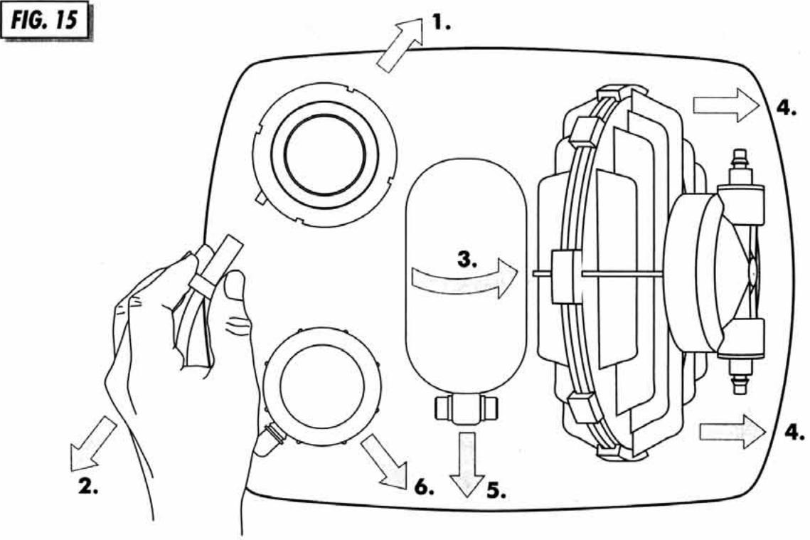
If complete removal is required, slide out of clips using a twisting action (Arrow 1 FIG 15). Grasp Valve Manifold and gently pull away from the Valve (Arrow 2). To refit, reverse the operation.
VALVE FILTER ATS/444 Replace every 1000 hours or sooner if heavily contaminated. Manually release Valve Filter Cover Clips by levering with fingers (FIG 8). Carefully remove Valve Filter taking care not to drop dust into the working parts. Fit new Valve Filter by reversing the process.
BLEED INSERT ATS/447 Pull out of main body taking care not to dislodge the 4 'O' Rings. Inspect two small holes near the end (FIG 9). Clean every 1000 hours or sooner if heavily contaminated. Use strand of wire attached to bleed insert.
DIAPHRAGM ASSEMBLY ATS/443 Replace every 3000 hours. First remove Valve Filter (see above). Remove Spring ATS/442. Pull Drive Box in direction of Arrow (FIG 9) using pliers on lug. Unscrew large black ring nut, gently prise off red cap, using a screwdriver in slot provided. Pull out Rubber Diaphragm by grasping outer rim. Re-fit Diaphragm Assembly ATS/443 taking care not to remove the pre-lubrication on the shaft. If the Spring, ATS/442 shows any sign of corrosion, replace it.
Fit new Diaphragm Assembly by reversing the operation, ensuring that the semi circular location engages in the recess on the main body. When replacing the Drive Box push hard until a click is heard indicating proper engagement. Prior to fitting the Filter and Cover, push Drive Box from end to end. An audible click should be heard, indicating proper operation.
DIAPHRAGM PUMP AJS/2004 The Pump is located on the right of the Power Unit 'A' (FIG 2). It needs no maintenance but, in the rare event of failure, it is removed by first unscrewing the Pressure Bottle ATS/436 in the direction of arrow 3 (FIG 15). Tilt Pump AJS/2004 and unclip by sliding in the direction of arrows 4 (FIG 15). Remove both rubber elbows. Unscrew 4 Nuts, on the Pump Head, ATS/445 and ATS/446 (FIG 7), warm tube ends and pull off gently, noting their positions.
When replacing the Pump, make sure that the arrows on the Pump Heads point towards the top of the Power Unit. Occasionally, debris may enter the Non Return Valves ATS/445 and ATS/446 (FIG 7). These can be unscrewed using long nosed pliers. Wash out and blow through. These components can be replaced if damaged.
RELIEF VALVE AJS/2006 The Valve is located at bottom left of Power Unit (FIG 2). To replace Diaphragm ATS/435, unscrew top with moulded lugs, this will expose Diaphragm for replacement. To fit a different Pressure Relief Module 'X' (FIG 11), AJS/2014, AJS/2016, AJS/2018, remove rubber elbow in direction of arrow. Unscrew the complete top inclusive of Spigot section, this will expose the existing Relief Module.
To replace or remove complete Relief Valve, first remove the Pump as described under Diaphragm Pump. Then tilt and slide Bottle Holder in direction of arrow 5 (FIG 15), unclip the Relief Valve in direction of arrow 6. Unscrew 3 nuts on the Relief Valve, warm tube ends and pull off gently noting their positions.
MANIFOLD ASSEMBLY AJS/2008 The Manifold is located by friction fit in the skirt of the Case Base (FIG 10). If it is damaged it can be replaced. Unscrew 4 Nuts and remove tubes. Pull out Vacuum Pipe 'A'. Cut Vacuum Pipe 'B' (FIG 6) close to rubber bush as it is glued for transportation. Lever Manifold from Case Base. Replace with new unit. Both Vacuum Pipes 'A' & 'B' need only be pushed in.
- TROUBLE SHOOTING
| FAULT | CAUSE | REMEDY |
| 1. Unit does not spray | a. Vacuum Pump not switched onb. Vacuum line not airtightc. Constricted Vacuum Supply Pipe (E)d. Chemical Container is emptye. Intake Filter (D) blockedf. Pressure Line (F) blockedg. Spray Nozzle AJS/2415 blockedh. Unsuitable chemical being usedi. Pump AJS/2004 faultyj. Directional Valve ATS/425 faultyk. Relief Valve AJS/2006 faulty | a. Switch on Vacuum Pumpb. Check that Vacuum is reaching Power Unit by pulling Supply Pipe out and test with finger.Check Vacuum Pipe adaptor is correctly installedc. Check for kinks and overtightened Cable Tiesd. Fill Containere. Clean Filterf. Clear blockage, check for constrictions, kinks and tight Cable Tiesg. Disassemble, clean Nozzle (Fig 12)h. Change to recognised Teat Disinfectanti. Check Pump and repair or replacej. Check Valve and repair or replacek. Check Valve and clean, repair or replace |
| 2. Nozzle (Fig.12) does not shut off cleanly or Leaks | a. Air in pressure Line (F)b. Control Valve ATS/405 dirty or damaged | a. Vent as described under “8. Initial start up”b. Clean or replace Control Valve |
| 3. Chemical running out of Power Unit | a. Loose Connector Nutb. Defective Pump or Relief Valve | a. Locate leak and tighten Nutb. Check Units and repair or replace |
| 4. Unit pressurised when Vacuum switched off | Relief Valve faulty | Repair or replace |
| 5. Chemical leaks into Vacuum line | Relief Valve or Pump faulty | Immediately disconnect Vacuum line & plug it. Repair or replace defective part(s). |
- TECHNICAL DATA
| Power Source | Vacuum 12-15 in. Hg (40-50Kpa) | Maximum No. of Guns operated simultaneously | 3 |
| Chemical Consumption | 6-12 ml/Sec | Maximum No. of Guns per Power Unit | 50 |
| Air Consumption | 50l/min (1.8cfm Atmospheric Air @ 50Kpa) | Maximum length of Pressure Line | 80ft |
| Spray Pressure | (Low Pressure Module) 40 psi(2.75BAR) @ 46Kpa (13.5Hg)AJS/2014(Standard Pressure Module) 50psi(3.4BAR) @ 46Kpa (13.5Hg) AJS/2016(High Pressure Module) 60psi(4.1BAR) @ 46Kpa (13.5Hg) AJS/2018 | 25m |

The Coburn Company, Inc. · P O Box 147 · Whitewater, WI 53190 U.S.A.
phone 800-776-7042 262-473-2822 · fax 800-776-7044 262-473-3522
- AMBIC™
- JETSTREAM
- SCHEMATIC LAYOUT SCHEMA GENERALE
- SCHEMATISCHER GRUNDRISS SCHEMATISCH OVERZICHT
- SCHEMA SYNOPTIQUE DISPOSICIÓN ESQUEMÁTICA
- INSTALLATION INSTALLAZIONE
- INSTALLATION INSTALLATIE
- INSTALLATION INSTALACIÓN
- MAINTENANCE MANUTENZIONE
- INSTANDHALTUNG ONDERHOUD
- ENTRETIEN MANTENIMIENTO
- INSTALLATION
- INITIAL START UP
- OPERATION
- MAINTENANCE
Marque : Coburn
Modèle : AJS1000 Ambic Jet
Catégorie : Matériel agricole