Bender Timer Control - Module de contrôle de minuterie Coburn - Notice d'utilisation et mode d'emploi gratuit
Retrouvez gratuitement la notice de l'appareil Bender Timer Control Coburn au format PDF.


Questions des utilisateurs sur Bender Timer Control Coburn
0 question sur cet appareil. Repondez a celles que vous connaissez ou posez la votre.
Poser une nouvelle question sur cet appareil
Téléchargez la notice de votre Module de contrôle de minuterie au format PDF gratuitement ! Retrouvez votre notice Bender Timer Control - Coburn et reprennez votre appareil électronique en main. Sur cette page sont publiés tous les documents nécessaires à l'utilisation de votre appareil Bender Timer Control de la marque Coburn.
MODE D'EMPLOI Bender Timer Control Coburn
Bender
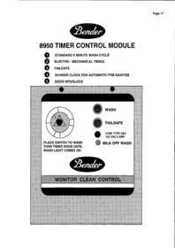
8950 TIMER CONTROL MODULE
1 STANDARD 8 MINUTE WASH CYCLE
2 ELECTRO - MECHANICAL TIMING
3 FAILSAFE
4 24-HOUR CLOCK FOR AUTOMATIC PRE-SANITIZE
5 DOOR INTERLOCK

PLACE SWITCH TO WASH TURN TIMER KNOB UNTIL WASH LIGHT COMES ON

WASH

FAILSAFE

FUSE TYPE 3AG
125 VAC 2 AMP

MILK OFF WASH
Bender
MONITOR CLEAN CONTROL

8950 TIMER CONTROL MODULE INSTALLATION
- Install the module on the wall.
A. If possible, do not install above the wash vat.
B. 10' of 1/4" OD rigid tubing has been provided for the pressure switch line.
- Route the 1/4" OD rigid tubing between the flexible tubing on the pressure switch and the rubber bushing, on the input plate. Tubing should be sloped for self-draining so condensation does not accumulate.
- Wiring the control box: All wiring on installation should be done according to National Electrical Code and Local Regulations. Be absolutely certain this unit is grounded to an approved ground. Ground both modules.
A. POWER INPUT: 115 VAC 60 HZ. SINGLE PHASE. Input terminal L1, N for Neutral and Ground.
B. The terminal blocks marked 1 through 6 are to be interconnected 1 to 1, 2 to 2, 3 to 3, 4 to 4, 5 to 5 and 6 to 6 between the control and dispenser modules.
C. REMOTE WATER VALVES: The HOT valve is wired to 3 and the COLD valve is wired to 6 on the terminal block marked 1 through 6. The water valve neutrals are wired to the main neutral buss on the 16 position terminal block.
The REMOTE WATER VALVE coils must not have a rating higher than 2 amp. Do not fill the wash tank or vat faster than the time it takes to put the required amount of chemical in.
This unit has a door interlock. Pull the button out to operate the unit with the door open. Door screws must be tightened far enough to energize this interlock.
ADJUSTMENTS
- FAILSAFE TIMER--This timer is adjustable up to 100 minutes. It monitors the time it takes to complete the wash cycle through the second rinse. It should be adjusted to a time greater than the time it takes to complete the entire wash cycle. Keep in mind, water pressure changes, cow drinking, etc. If this timer times out, the failsafe light will come on and the control unit stops.
- FIRST RINSE AND WASH--See 9750 sequence control rinse and wash notes for ADJUSTMENT procedure.
- 24-HOUR CLOCK--The 24-hour clock will only advance the main timer when the dial is in the "OFF" position, between the second rinse and sanitize.
A. Pull two (orange) trippers "ON" one hour before milking.
B. Turn (orange) tripper dial to time pointer to set time of day.
ALL WIRING ON INSTALATION SHOULD BE DONE ACCORDING TO NATIONAL ELECTRICAL CODE AND LOCAL REGULATIONS.
ALL OUTPUT LOADS GREATE
THAN 1 AMP. REQUIRE A 115 VAC
CONTACTOR INTERFACE.
115 VAC 60 HZ SINGLE PHASE 3 WRITE.
BE ABSOLUTELY CERTAIN THIS UNIT IS
GROUNDED TO AN APPROVED GROUND.
3 FOR WARM SANITIZE: CONNECT THE BLACK/
PURPLE WIDTH TO A CAPPED BLACK WRITE. NEXT TO
THE BLACK WRITE (labelled HOT) ON THE WHITE
TIME8 CONNECTOR.
FOR WARM SANITIZE: CONNECT THE BLACK /
PURPLE WRITE TO A CAPPED BLACK WRITE. NEXT TO
THE BLACK WRITE (labelled HOT) ON THE WHITE
TIMER CONNECTOR.
FOR WARM ACID: CONNECT THE BLACK / ORANGE
WRITE TO A CAPPED BLACK WRITE. NEXT TO A
BLACK WRITE (labelled HOT) ON THE WHITE TIMER
CONNECTOR.
FOR POWDER DETERGENT: MOVE THE BLACK
WRITE (labelled HOT) FROM THE BLACK WRITE
TERMINAL TO THE BLACK / SLIVER WRITE
TERMINAL ON THE WHITE TIMER CONNECTOR.


8950 WIRING DIAGRAM
FOR PODDER DETERGENT: MOVE THE BLACK WRITE (labelled hot) FROM THE BLACK WRITE
TERMINAL TO THE BLACK / SILVER WRITE
TERMINAL ON THE WHITE TIMER CONNECTION.


9750 SEQUENCE CONTROL

8950 PARTS


ITEM DESCRIPTION PART NO.
| 1 | ON AND FAIL LAMP | 8249 |
| 2 | FUSEHOLDER | 2832 |
| 3 | TOGGLE SWITCH | 6265 |
| 4 | TIMER KNOB | 8254 |
| 5 | DIAL INDICATOR | 8234 |
| 6 | S. S. SCREW 10-24 | 6140 |
| 7 | FUSE - 115 VAC 2 AMP | 2831 |
| 8 | SPACER | 6139 |
| 9 | PRESSURE SWTCH | 5513 |
| 10 | TERMINAL BLOCK 6 POS. | 8836 |
| 11 | S.S. SCREW 10-32 | 6135 |
| 12 | RETENTION WASHER | 2677 |
| 13 | TERMINAL BLOCK 16 POS. | 8886 |
ITEM DESCRIPTION PART NO.
| 14 | FAIL TIMER - 100 MINUTE | 8926 |
| 15 | S.S.SCREW 8-32 X 1.0" | 6159 |
| 16 | TIMER BRACKET | 8232 |
| 17 | TIMER | 9750 |
| TIMER MOTOR - .8 RPM 120VAC / 50-60 HZ | 9755 | |
| 18 | 24-HOUR CLOCK | 9257 |
| 19 | S.S. CASE ASSEMBLY | 8920 |
| 20 | SHEET METAL NUT 10-24 | 6136 |
| 21 | DOOR SWITCH | 9258 |
| S.S. NUT 6-32 (not shown) | 6121 |
Bender
8950 TROUBLESHOOTING GUIDE
PROBLEM
- Vacuum pump does not start for milking.
POSSIBLE CAUSE
a. No voltage on input L1.
b. Circuit breaker tripped.
c. Defective circuit breaker.
d. Defective MILK OFF WASH switch.
e. Defective safety switch.
f. Defective door interlock switch.
-
Unable to start the washing cycle.
-
On light only.
-
No water on any cycle.
-
Fail light with wash vat overflowing on any fill.
-
Milk pump does not run at the end of each cycle.
-
Fail light after wash vat is filled.
-
Fail light intermittently in the second rinse or wash.
-
Sanitize works morning or evening only
-
Sanitizes immediately after washing.
-
Sanitize does not start by itself
a. Defective MILK OFF WASH switch.
a. Defective fail timer.
a. Defective pressure switch.
a. Defective pressure switch.
b. Air leak on pressure switch tubing.
a. Defective L.O. relay.
b. Defective main timer.
a. Pressure switch not starting the main timer.
a. Changing water pressure and Failsafe timer not adjusted long enough.
a. Only one tripper on 24-hour clock pulled out.
a. 24-hour clock has not turned itself off.
a. No trippers on 24-hour clock pulled out.
b. Defective 24-hour clock.
c. Defective main timer.
Marque : Coburn
Modèle : Bender Timer Control
Catégorie : Module de contrôle de minuterie