
E5EN - Contrôleur de température OMRON - Notice d'utilisation et mode d'emploi gratuit
Retrouvez gratuitement la notice de l'appareil E5EN OMRON au format PDF.

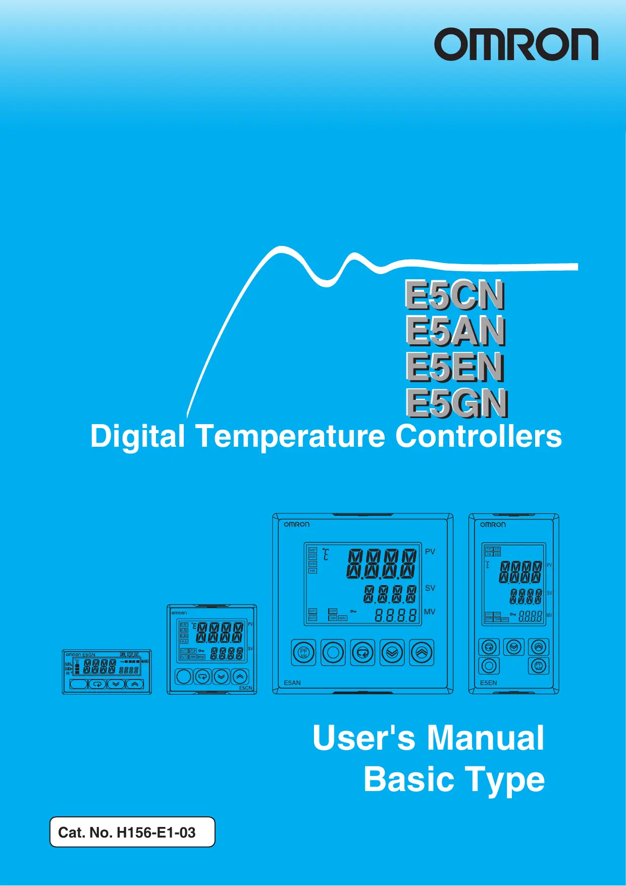

| Type de produit | Contrôleur de température numérique |
| Marque | OMRON |
| Modèle | E5EN |
| Dimensions (L × H × P) | 96 × 96 × 78 mm (approx.) |
| Poids | Environ 300 g (hors accessoires) |
| Alimentation | 100 à 240 VAC, 50/60 Hz ou 24 VAC/VDC |
| Consommation | Environ 7 VA (AC) / 3 W (DC) |
| Types d'entrée | Thermocouple (K, J, T, E, N, R, S, B, W, PLII), Pt100, JPt100, ES1B infrarouge, 4-20 mA, 0-20 mA, 1-5 V, 0-5 V, 0-10 V, 0-50 mV |
| Sortie de contrôle 1 | Relais, tension (SSR) ou courant |
| Sortie de contrôle 2 (en option) | Relais longue durée, tension (SSR) ou courant |
| Sorties auxiliaires (alarmes) | Jusqu'à 3 sorties relais (250 VAC, 3 A) |
| Fonctions de contrôle | PID, ON/OFF, auto-tuning (AT), self-tuning (ST), chauffage/refroidissement |
| Alarmes | Alarmes de valeur absolue, de dérive, de variation de PV, de boucle (LBA), de surintensité, de court-circuit chauffage (HS) |
| Communications | RS-485 (CompoWay/F, Modbus) ou RS-232C (en option) |
| Affichage | PV (rouge/vert), SV (vert), MV (vert) - affichage 3 niveaux |
| Indice de protection | IP66 (face avant), IP20 (boîtier arrière), IP00 (bornes) |
| Température ambiante | -10 à 55 °C (sans condensation) |
| Humidité ambiante | 25 à 85 % HR (sans condensation) |
| Entretien et nettoyage | Nettoyer avec un chiffon doux imbibé d'alcool ; ne pas utiliser de diluant |
| Sécurité | Conforme UL, CSA, IEC, Directive CEM ; bornes à vis à serrer à 0,74-0,90 N·m |
| Pièces détachées et réparabilité | Boîtier, bornier, couvercle de bornes, ferrite ; réparation par OMRON uniquement |
| Informations générales | Contrôleur de température numérique à microprocesseur, montage sur panneau, 355 pages de manuel |
FOIRE AUX QUESTIONS - E5EN OMRON
Questions des utilisateurs sur E5EN OMRON
0 question sur cet appareil. Repondez a celles que vous connaissez ou posez la votre.
Poser une nouvelle question sur cet appareil
Téléchargez la notice de votre Contrôleur de température au format PDF gratuitement ! Retrouvez votre notice E5EN - OMRON et reprennez votre appareil électronique en main. Sur cette page sont publiés tous les documents nécessaires à l'utilisation de votre appareil E5EN de la marque OMRON.
MODE D'EMPLOI E5EN OMRON
E5CN
E5AN
E5EN
E5GN
Digital Temperature Controllers
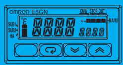
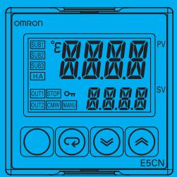
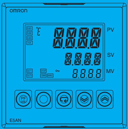
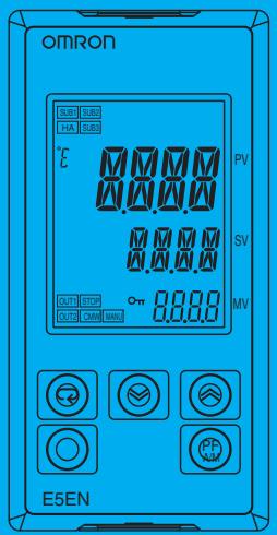
User's Manual
Basic Type
E5CN/E5AN/E5EN/E5GN Digital Temperature Controllers
User's Manual
Basic Type
Revised September 2009
Preface
The E5CN, E5CN-U, E5AN, E5EN, and E5GN are Digital Temperature Controllers. The E5CN and E5CN-U are both compact temperature controllers, with the E5CN featuring screw terminal connections, and the E5CN-U featuring socket pin connections. The E5GN can be connected using screw terminals or screwless clamp terminals. The main functions and characteristics of these Digital Temperature Controllers are as follows:
- Any of the following types of input can be used: thermocouple, platinum resistance thermometer, infrared sensor, analog voltage, or analog current.
- Either standard or heating/cooling control can be performed.
- Both auto-tuning and self-tuning are supported.
- Event inputs can be used to switch set points (multi-SP function), switch between RUN and STOP status, switch between automatic and manual operation, start/reset the simple program function, and perform other operations. (Event inputs are not applicable to the E5CN-U.)
- Heater burnout detection, heater short (HS) alarms, and heater overcurrent (OC) functions are supported. (Applicable to E5CN, E5AN, E5EN, and E5GN models with heater burnout detection function.)
- Communications are supported. (Applicable to E5CN, E5AN, E5EN, and E5GN models with communications.)
- User calibration of the sensor input is supported.
- The structure is waterproof (IP66). (Not applicable to the E5CN-U.)
- Conforms to UL, CSA, and IEC safety standards and EMC Directive.
- The PV display color can be switched to make process status easy to understand at a glance.
This manual describes the E5CN, E5CN-U, E5AN, E5EN, and E5GN. Read this manual thoroughly and be sure you understand it before attempting to use the Digital Temperature Controller and use the Digital Temperature Controller correctly according to the information provided. Keep this manual in a safe place for easy reference. Refer to the following manual for further information on communications: E5CN/E5AN/E5EN/E5GN Digital Temperature Controllers Communications Manual Basic Type (Cat. No. H158).
Refer to the following manual for information on the Advanced Type Controllers: E5CN/E5AN/E5EN-H Digital Temperature Controllers User's Manual Advanced Type (Cat. No. H157).
Visual Aids
The following headings appear in the left column of the manual to help you locate different types of information.
Note Indicates information of particular interest for efficient and convenient operation of the product.
1,2,3... 1. Indicates lists of one sort or another, such as procedures, checklists, etc.
OMRON, 2008
All rights reserved. No part of this publication may be reproduced, stored in a retrieval system, or transmitted, in any form, or by any means, mechanical, electronic, photocopying, recording, or otherwise, without the prior written permission of OMRON.
No patent liability is assumed with respect to the use of the information contained herein. Moreover, because OMRON is constantly striving to improve its high-quality products, the information contained in this manual is subject to change without notice. Every precaution has been taken in the preparation of this manual. Nevertheless, OMRON assumes no responsibility for errors or omissions. Neither is any liability assumed for damages resulting from the use of the information contained in this publication.
| Read and Understand this Manual |
| Please read and understand this manual before using the products. Please consult your OMRON representative if you have any questions or comments. |
| Warranty, Limitations of Liability |
| WARRANTY OMRON's exclusive warranty is that the products are free from defects in materials and workmanship for a period of one year (or other period if specified) from date of sale by OMRON. OMRON MAKES NO WARRANTY OR REPRESENTATION, EXPRESS OR IMPLIED, REGARDING NON-INFRINGEMENT, MERCHANTABILITY, OR FITNESS FOR PARTICULAR PURPOSE OF THE PRODUCTS. ANY BUYER OR USER ACKNOWLEDGES THAT THE BUYER OR USER ALONE HAS DETERMINED THAT THE PRODUCTS WILL SUITABLY MEET THE REQUIREMENTS OF THEIR INTENDED USE. OMRON DISCLAIMS ALL OTHER WARRANTYES, EXPRESS OR IMPLIED. |
| LIMITATIONS OF LIABILITY OMRON SHALL NOT BE RESPONSIBLE FOR SPECIAL, INDIRECT, OR CONSEQUENTIAL DAMAGES, LOSS OF PROFITS OR COMMERCIAL LOSS IN ANY WAY CONNECTED WITH THE PRODUCTS, WHETHER SUCH CLAIM IS BASED ON CONTRACT, WARRANTY, NEGLIGENCE, OR STRICT LIABILITY. In no event shall the responsibility of OMRON for any act exceed the individual price of the product on which liability is asserted. IN NO EVENT SHALL OMRON BE RESPONSIBLE FOR WARRANTY, REPAIR, OR OTHER CLAIMS REGARDING THE PRODUCTS UNLESS OMRON'S ANALYSIS CONFirms THAT THE PRODUCTSWere PROPERLY HANDLED, STORED, INSTALLED, AND MAINTAINED AND NOT SUBJECT TO CONTAMINATION, ABUSE, MISUSE, OR INAPPROPRIATE MODIFICATION OR REPAIR. |
| Application Considerations |
| SUITABILITY FOR USE OMRON shall not be responsible for conformity with any standards, codes, or regulations that apply to the combination of the products in the customer's application or use of the products. At the customer's request, OMRON will provide applicable third party certification documents identifying ratings and limitations of use that apply to the products. This information by itself is not sufficient for a complete determination of the suitability of the products in combination with the end product, machine, system, or other application or use. The following are some examples of applications for which particular attention must be given. This is not intended to be an exhaustive list of all possible uses of the products, nor is it intended to imply that the uses listed may be suitable for the products: • Outdoor use, uses involving potential chemical contamination or electrical interference, or conditions or uses not described in this manual. • Nuclear energy control systems, combustion systems, railroad systems, aviation systems, medical equipment, amusement machines, vehicles, safety equipment, and installations subject to separate industry or government regulations. • Systems, machines, and equipment that could present a risk to life or property. Please know and observe all prohibitions of use applicable to the products. NEVER USE THE PRODUCTS FOR AN APPLICATION INVOLVING SERIOUS RISK TO LIFE OR PROPERTY WITHOUT ENSURING THAT THE SYSTEM AS A WHOLE HAS BEEN DESIGNED TO ADDRESS THE RISKS, AND THAT THE OMRON PRODUCTS ARE PROPERLY RATED AND INSTALLED FOR THE INTENDED USE WITHIN THE OVERALL EQUIPMENT OR SYSTEM. |
| PROGRAMMABLE PRODUCTS OMRON shall not be responsible for the user's programming of a programmable product, or any consequence thereof. |
| Disclaimers |
| CHANGE IN SPECIFICATIONS Product specifications and accessories may be changed at any time based on improvements and other reasons. It is our practice to change model numbers when published ratings or features are changed, or when significant construction changes are made. However, some specifications of the products may be changed without any notice. When in doubt, special model numbers may be assigned to fix or establish key specifications for your application on your request. Please consult with your OMRON representative at any time to confirm actual specifications of purchased products. |
| DIMENSIONS AND WEIGHTS Dimensions and weights are nominal and are not to be used for manufacturing purposes, even when tolerances are shown. |
| PERFORMANCE DATA Performance data given in this manual is provided as a guide for the user in determining suitability and does not constitute a warranty. It may represent the result of OMRON's test conditions, and the users must correlate it to actual application requirements. Actual performance is subject to the OMRON Warranty and Limitations of Liability. |
| ERRORS AND OMISSIONS The information in this manual has been carefully checked and is believed to be accurate; however, no responsibility is assumed for clerical, typographical, or proofreading errors, or omissions. |
Safety Precautions
Definition of Precautionary Information
The following notation is used in this manual to provide precautions required to ensure safe usage of the product.
The safety precautions that are provided are extremely important to safety. Always read and heed the information provided in all safety precautions.
The following notation is used.

CAUTION
Indicates a potentially hazardous situation which, if not avoided, is likely to result in minor or moderate injury or in property damage.
Symbols
| Symbol | Meaning | |
| Caution | ! | General Caution Indicates non-specific general cautions, warnings, and dangers. |
| ! | Electrical Shock Caution Indicates possibility of electric shock under specific conditions. | |
| Prohibition | General Prohibition Indicates non-specific general prohibitions. | |
| Mandatory Caution | General Caution Indicates non-specific general cautions, warnings, and dangers. | |
| CAUTION | |
| Do not touch the terminals while power is being supplied. Doing so may occasionally result in minor injury due to electric shock. | 4 |
| Do not allow pieces of metal, wire clippings, or fine metallic shavings or filings from installation to enter the product. Doing so may occasionally result in electric shock, fire, or malfunction. | 6 |
| Do not use the product where subject to flammable or explosive gas. Otherwise, minor injury from explosion may occasionally occur. | |
| Never disassemble, modify, or repair the product or touch any of the internal parts. Minor electric shock, fire, or malfunction may occasionally occur. | |
| CAUTION - Risk of Fire and Electric Shock a) This product is UL listed as Open Type Process Control Equipment. It must be mounted in an enclosure that does not allow fire to escape externally. b) More than one disconnect switch may be required to de-energize the equipment before servicing the product. c) Signal inputs are SELV, limited energy. *1 d) Caution: To reduce the risk of fire or electric shock, do not inter-connect the outputs of different Class 2 circuits. *2 | 7 |
| If the output relays are used past their life expectancy, contact fusing or burning may occasionally occur. Always consider the application conditions and use the output relays within their rated load and electrical life expectancy. The life expectancy of output relays varies considerably with the output load and switching conditions. | |
1 A SELV circuit is one separated from the power supply with double insulation or reinforced insulation, that does not exceed 30 V r.m.s. and 42.4 V peak or 60 VDC.
2 A class 2 power supply is one tested and certified by UL as having the current and voltage of the secondary output restricted to specific levels.
| CAUTION | |
| Tighten the terminal screws to between 0.74 and 0.90 N·m. Loose screws may occasionally result in fire. *3 | |
| Set the parameters of the product so that they are suitable for the system being controlled. If they are not suitable, unexpected operation may occasionally result in property damage or accidents. | |
| A malfunction in the Temperature Controller may occasionally make control operations impossible or prevent alarm outputs, resulting in property damage. To maintain safety in the event of malfunction of the Temperature Controller, take appropriate safety measures, such as installing a monitoring device on a separate line. | |
| A semiconductor is used in the output section of long-life relays. If excessive noise or surge is impressed on the output terminals, a short-circuit failure is likely to occur. If the output remains shorted, fire will occur due to overheating of the heater or other cause. Take measures in the overall system to prevent excessive temperature increase and to prevent fire from spreading. | |
| When inserting the body of the Temperature Controller into the case, confirm that the hooks on the top and bottom are securely engaged with the case. If the body of the Temperature Controller is not inserted properly, faulty contact in the terminal section or reduced water resistance may occasionally result in fire or mal-function. | |
*3 The tightening torque is 0.5 N·m for the E5CN-U and 0.43 to 0.58 N·m for the E5GN. The terminal torque is 0.5 to 0.6 N·m for auxiliary output 2 on the E5GN.
Precautions for Safe Use
Be sure to observe the following precautions to prevent operation failure, malfunction, or adverse affects on the performance and functions of the product. Not doing so may occasionally result in unexpected events. Use the product within the specifications.
1) The product is designed for indoor use only. Do not use the product outdoors or in any of the following locations. Do not use or store the product in any of the following locations.
- Places directly subject to heat radiated from heating equipment.
- Places subject to splashing liquid or oil atmosphere.
- Places subject to direct sunlight.
- Places subject to dust or corrosive gas (in particular, sulfide gas and ammonia gas).
- Places subject to intense temperature change.
- Places subject to icing and condensation.
- Places subject to vibration and large shocks.
2) Use and store the Digital Temperature Controller within the rated ambient temperature and humidity.
Gang-mounting two or more temperature controllers, or mounting temperature controllers above each other may cause heat to build up inside the temperature controllers, which will shorten their service life. In such a case, use forced cooling by fans or other means of air ventilation to cool down the Digital Temperature Controllers.
3) To allow heat to escape, do not block the area around the product. Do not block the ventilation holes on the product.
4) Be sure to wire properly with correct polarity of terminals.
5) Use the specified size of crimp terminals for the E5CN, E5AN, or E5EN (M3.5, width of 7.2 mm or less). For open-wired connections to the E5CN, E5AN, or E5EN, use stranded or solid copper wires with a gauge of AWG24 to AWG14 (equal to a cross-sectional area of 0.205 to 2.081 mm²). (The stripping length is 5 to 6 mm.) Up to two wires of the same size and type or two crimp terminals can be connected to one terminal. Do not connect more than two wires or more than two crimp terminals to the same terminal.
Use the specified size of crimp terminals for the E5GN (M3.0, width of 5.8 mm or less). For open-wired connections to the E5GN, use stranded or solid copper wires with a gauge of AWG24 to AWG18 (equal to a cross-sectional area of 0.205 to 0.8231 mm²). (The stripping length for screw terminals is 6 to 8 mm. The stripping length for screwless clamp terminals is 10 mm. The stripping length for auxiliary output 2 is 6 mm.) Up to two wires of the same size and type or two crimp terminals can be connected to one terminal. Do not connect more than two wires or more than two crimp terminals to the same terminal.
Ferrules for screwless clamp terminals must be 0.8 to 1.4mm in diameter and the exposed conductor must be 8 to 12mm in length. Ferrules for auxiliary output 2 must be 0.8 to 1.4mm in diameter and the exposed conductor must be 6mm in length.
6) Do not wire the terminals which are not used.
7) To avoid inductive noise, keep the wiring for the Digital Temperature Controller's terminal block away from power cables carry high voltages or large currents. Also, do not wire power lines together with or parallel to Digital Temperature Controller wiring. Using shielded cables and using separate conduits or ducts is recommended.
Attach a surge suppressor or noise filter to peripheral devices that generate noise (in particular, motors, transformers, solenoids, magnetic coils or other equipment that have an inductance component).
When a noise filter is used at the power supply, first check the voltage or current, and attach the noise filter as close as possible to the temperature controller.
Allow as much space as possible between the Digital Temperature Controller and devices that generate powerful high frequencies (high-frequency welders, high-frequency sewing machines, etc.) or surge.
8) Use this product within the rated load and power supply.
9) Make sure that the rated voltage is attained within two seconds of turning ON the power using a switch or relay contact. If the voltage is applied gradually, the power may not be reset or output malfunctions may occur.
10) Make sure that the Temperature Controller has 30 minutes or more to warm up after turning ON the power before starting actual control operations to ensure the correct temperature display.
11) When executing self-tuning, turn ON power for the load (e.g., heater) at the same time as or before supplying power to the Digital Temperature Controller. If power is turned ON for the Digital Temperature Controller before turning ON power for the load, self-tuning will not be performed properly and optimum control will not be achieved.
12) A switch or circuit breaker should be provided close to this unit. The switch or circuit breaker should be within easy reach of the operator, and must be marked as a disconnecting means for this unit.
13) Always turn OFF the power supply before removing the body of the E5CN, E5AN, or E5EN from the case, and never touch nor apply shock to the terminals or electronic components. When inserting the interior of the product, do not allow the electronic components to touch the case.
Always turn OFF the power supply before removing the terminal block from the E5GN, and never touch nor apply shock to the terminals or electronic components.
14) Do not use paint thinner or similar chemical to clean with. Use standard grade alcohol.
15) Design system (control panel, etc.) considering the 2 second of delay that the controller's output to be set after power ON.
16) The output may turn OFF when shifting to certain levels. Take this into consideration when performing control.
17) The number of EEPROM write operations is limited. Therefore, use RAM write mode when frequently overwriting data during communications or other operations.
18) Always touch a grounded piece of metal before touching the Digital Temperature Controller to discharge static electricity from your body.
19) Do not remove the terminal block from the E5CN, E5AN, or E5EN. Doing so may result in failure or malfunction.
20) Control outputs that are voltage outputs are not isolated from the internal circuits. When using a grounded thermocouple, do not connect any of the control output terminals to ground. (Doing so may result in an unwanted circuit path, causing error in the measured temperature.)
21) When replacing the body of the E5CN, E5AN, or E5EN, check the condition of the terminals. If corroded terminals are used, contact failure in the terminals may cause the temperature inside the E5CN, E5AN, or E5EN to increase, possibly resulting in fire. If the terminals are corroded, replace the case as well.
When removing the terminal block of the E5GN to replace the Digital Temperature Controller, check the condition of the terminals. If corroded terminals are used, contact failure in the terminals may cause the temperature inside the Digital Temperature Controller to increase, possibly resulting in fire. If the terminals are corroded, replace the terminal block as well.
22) Use suitable tools when taking the Digital Temperature Controller apart for disposal. Sharp parts inside the Digital Temperature Controller may cause injury.
23) When applying Lloyd's standards, install the Digital Temperature Controller according to the requirements given in Shipping Standards.
24) Do not use the Temperature Controller if the front sheet is peeling off or torn.
Service Life
Use the Temperature Controller within the following temperature and humidity ranges:
Temperature: -10 to 55^ (with no icing or condensation), Humidity: 25% to 85%
If the Controller is installed inside a control board, the ambient temperature must be kept to under 55^ , including the temperature around the Controller.
The service life of electronic devices like Temperature Controllers is determined not only by the number of times the relay is switched but also by the service life of internal electronic components. Component service life is affected by the ambient temperature: the higher the temperature, the shorter the service life and, the lower the temperature, the longer the service life. Therefore, the service life can be extended by lowering the temperature of the Temperature Controller.
When two or more Temperature Controllers are mounted horizontally close to each other or vertically next to one another, the internal temperature will increase due to heat radiated by the Temperature Controllers and the service life will decrease. In such a case, use forced cooling by fans or other means of air ventilation to cool down the Temperature Controllers. When providing forced cooling, however, be careful not to cool down the terminals sections alone to avoid measurement errors.
- Ambient Noise
To avoid inductive noise, keep the wiring for the Digital Temperature Controller's terminal block wiring away from power cables carrying high voltages or large currents. Also, do not wire power lines together with or parallel to Digital Temperature Controller wiring. Using shielded cables and using separate conduits or ducts is recommended.
Attach a surge suppressor or noise filter to peripheral devices that generate noise (in particular, motors, transformers, solenoids, magnetic coils or other equipment that have an inductance component). When a noise filter is used at the power supply, first check the voltage or current, and attach the noise filter as close as possible to the Temperature Controller.
Allow as much space as possible between the Digital Temperature Controller and devices that generate powerful high frequencies (high-frequency welders, high-frequency sewing machines, etc.) or surge.
- Ensuring Measurement Accuracy
When extending or connecting the thermocouple lead wire, be sure to use compensating wires that match the thermocouple types.
When extending or connecting the lead wire of the platinum resistance thermometer, be sure to use wires that have low resistance and keep the resistance of the three lead wires the same.
Mount the Temperature Controller so that it is horizontally level.
If the measurement accuracy is low, check to see if input shift has been set correctly.
Waterproofing
The degree of protection is as shown below. Sections without any specification on their degree of protection or those with IP 0 are not waterproof.
Front panel: IP66
Rear case: IP20, Terminal section: IP00
(E5CN-U: Front panel: IP50, rear case: IP20, terminals: IP00)
Precautions for Operation
1) It takes approximately two seconds for the outputs to turn ON from after the power supply is turned ON. Due consideration must be given to this time when incorporating Temperature Controllers into a control panel or similar device.
2) Make sure that the Temperature Controller has 30 minutes or more to warm up after turning ON the power before starting actual control operations to ensure the correct temperature display.
3) When executing self-tuning, turn ON power for the load (e.g., heater) at the same time as or before supplying power to the Temperature Controller. If power is turned ON for the Temperature Controller before turning ON power for the load, self-tuning will not be performed properly and optimum control will not be achieved. When starting operation after the Temperature Controller has warmed up, turn OFF the power and then turn it ON again at the same time as turning ON power for the load. (Instead of turning the Temperature Controller OFF and ON again, switching from STOP mode to RUN mode can also be used.)
4) Avoid using the Controller in places near a radio, television set, or wireless installing. The Controller may cause radio disturbance for these devices.
Shipping Standards
The E5CN, E5CN-H, E5AN, E5AN-H, E5EN, and E5EN-H comply with Lloyd's standards. When applying the standards, the following installation and wiring requirements must be met in the application.
■ Application Conditions
1) Installation Location
The E5CN, E5CN-H, E5AN, E5AN-H, E5EN, and E5EN-H comply with installation category ENV1 and ENV2 of Lloyd's standards. Therefore, they must be installed in a location equipped with air conditioning. They must therefore be installed in a location equipped with air conditioning. They cannot be used on the bridge or decks, or in a location subject to strong vibration.
2) Wiring Conditions
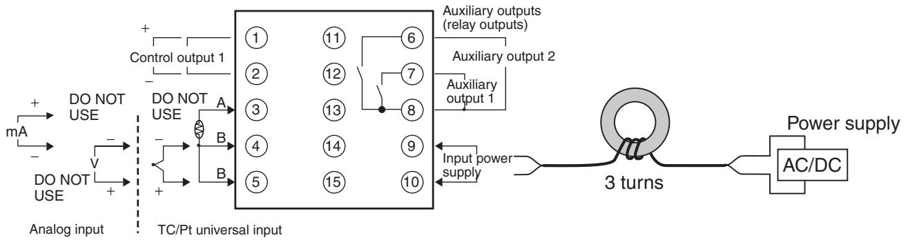
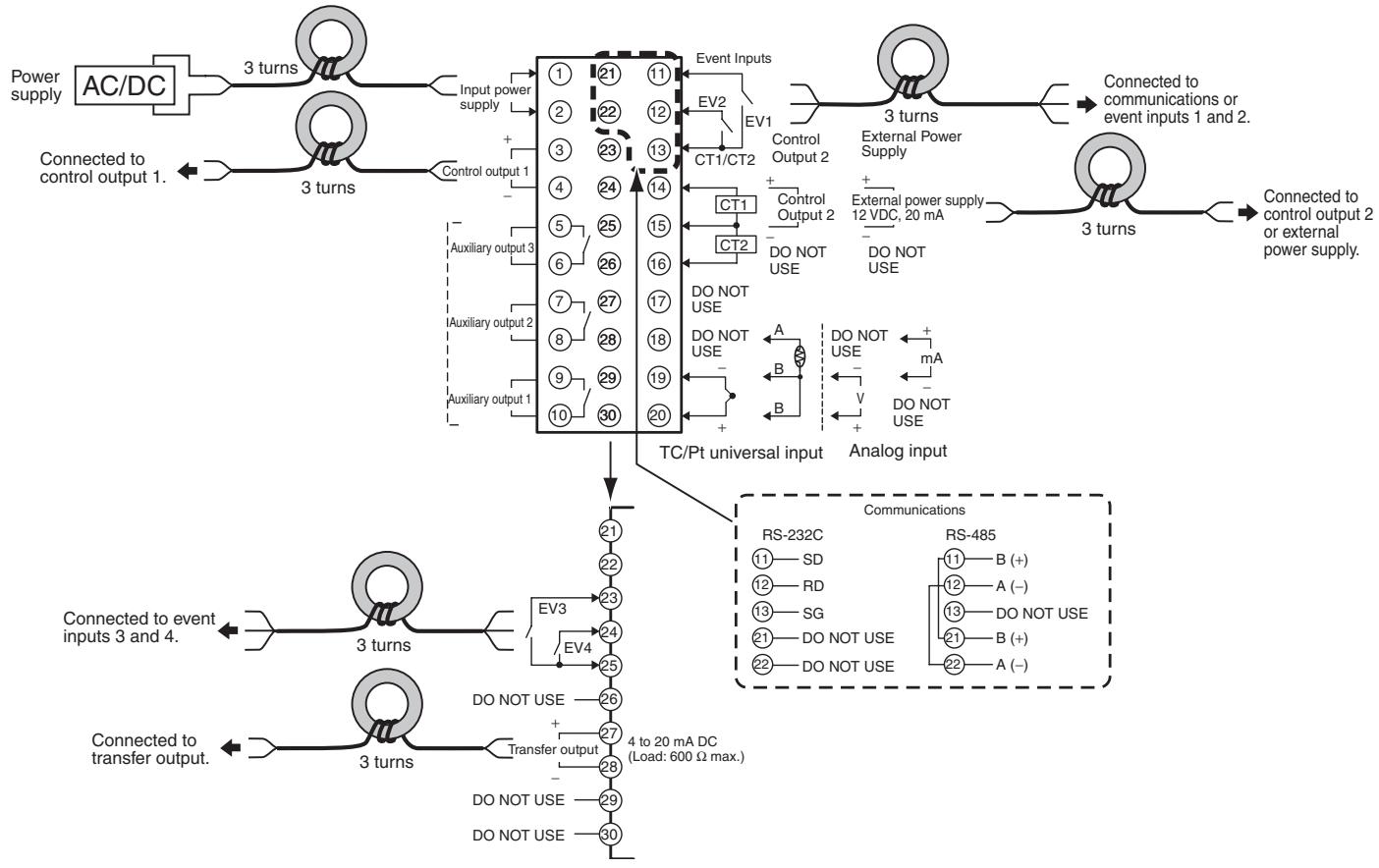
Install the recommended ferrite core and wrap the line around it three turns for the applicable lines (e.g., power supply cable line and signal lines) of the models listed in the following table. (See illustrations.) Install the ferrite cores as close to the terminal block of the E5□N as possible. (As a guideline, the ferrite core should be within 10 cm of the terminal block.)
- Lines Requiring Ferrite Cores
| Model | Signal and power lines provided with ferrite cores |
| E5CN, E5CN-U, or E5CN-H | Input power supply |
| E5EN, E5AN, E5EN-H, or E5AN-H | Input power supply and I/O lines (control outputs (1 and 2), communications, event inputs (1 to 4), transfer output, and external power supply (Advanced Type models do not have an external power supply.) |
Recommended Ferrite Core
| Manufacturer | Seiwa Electric Mfg. Co., Ltd. |
| Model | E04RA310190100 |
Ferrite Core Connection Examples
1. E5CN/E5CN-H
2. E5AN/E5EN/E5AN-H/E5EN-H
Preparations for Use
Be sure to thoroughly read and understand the manual provided with the product, and check the following points.
| Timing | Check point | Details |
| Purchasing the product | Product appearance | After purchase, check that the product and packaging are not dented or otherwise damaged. Damaged internal parts may prevent optimum control. |
| Product model and specifications | Make sure that the purchased product meets the required specifications. | |
| Setting the Unit | Product installation location | Provide sufficient space around the product for heat dissipation. Do not block the vents on the product. |
| Wiring | Terminal wiring | Do not subject the terminal screws to excessive stress (force) when tightening them. Make sure that there are no loose screws after tightening terminal screws to the specified torque of 0.74 to 0.90 N·m (see note). |
| Be sure to confirm the polarity for each terminal before wiring the terminal block and connectors. | ||
| Power supply inputs | Wire the power supply inputs correctly. Incorrect wiring will result in damage to the internal circuits. | |
| Operating environment | Ambient temperature | The ambient operating temperature for the product is -10 to 55°C (with no condensation or icing). To extend the service life of the product, install it in a location with an ambient temperature as low as possible. In locations exposed to high temperatures, if necessary, cool the products using a fan or other cooling method. |
| Vibration and shock | Check whether the standards related to shock and vibration are satisfied at the installation environment. (Install the product in locations where the conductors will not be subject to vibration or shock.) | |
| Foreign particles | Install the product in a location that is not subject to liquid or foreign particles entering the product. |
Note The tightening torque is 0.5 N·m for the E5CN-U and 0.43 to 0.58 N·m for the E5GN. The terminal torque is 0.5 to 0.6 N·m for auxiliary output 2 on the E5GN.
Upgraded Functions
The functionality of the E5CN, E5CN-U, E5AN, and E5EN was improved starting from December 2007 production.
The functionality of the E5GN was improved starting from August 2009 production.
The design of the front panel can be used to differentiate between the previous and upgraded models.
E5CN/CN-U
The upgraded Controllers are basically compatible with the previous Controllers. Terminal arrangements, terminal sizes, and panel mounting depth have not been changed.
E5AN/EN
Although the upgraded Controllers are compatible with the previous Controllers, terminal arrangements have been changed. Terminal sizes and panel mounting depth have not been changed.
E5GN
Model numbers have changed accompanying the introduction of universal input capability. The default setting of the input type parameter of the E5GN-□□□P (models with resistance thermometers) has been changed from a Pt100 resistance thermometer to a K thermocouple. Make sure the setting of the input type parameter agrees with the temperature sensor that is being used.
The terminal block has also been changed, which means the wiring methods and terminal arrangement are different.
Other changes outlined in the following tables. Refer to relevant pages in the manual for details.
| Previous models | ||||||||||||||||||||||||||||||||||||||||||||||||||||||||||||||||||||||||||||||||||||||||||||||||||||||||||||||||||||||||||||||||||||||||||||||||||||||||||||||||||||||||||||||||||||||||||||||||||||||||||||||||||||||||||||||||||||||||||||||||||||||||||||||
| E5CN/CN-U | ALM1 | °E | ||||||||||||||||||||||||||||||||||||||||||||||||||||||||||||||||||||||||||||||||||||||||||||||||||||||||||||||||||||||||||||||||||||||||||||||||||||||||||||||||||||||||||||||||||||||||||||||||||||||||||||||||||||||||||||||||||||||||||||||||||||||||||||
| ALM2 | ||||||||||||||||||||||||||||||||||||||||||||||||||||||||||||||||||||||||||||||||||||||||||||||||||||||||||||||||||||||||||||||||||||||||||||||||||||||||||||||||||||||||||||||||||||||||||||||||||||||||||||||||||||||||||||||||||||||||||||||||||||||||||||||
| ALM3 | ||||||||||||||||||||||||||||||||||||||||||||||||||||||||||||||||||||||||||||||||||||||||||||||||||||||||||||||||||||||||||||||||||||||||||||||||||||||||||||||||||||||||||||||||||||||||||||||||||||||||||||||||||||||||||||||||||||||||||||||||||||||||||||||
| HA | OUT1 | STOP | OUT1 | OUT2 | CMW | MANU | OUT1 | OUT2 | CMW | MANU | OUT1 | OUT2 | CMW | MANU | OUT1 | OUT2 | CMW | MANU | OUT1 | OUT2 | CMW | MANU | OUT1 | OUT2 | CMW | MANU | OUT1 | OUT2 | CMW | MANU | OUT1 | OUT2 | CMW | MANU | OUT1 | OUT2 | CMW | MANU | OUT1 OUT2 | CMW | MANU | OUT1 OUT2 | CMW | MANU | OUT1 OUT2 | CMW | MANU | OUT1 OUT2 | CMW | MANU | OUT1 OUT2 | CMW | MANU | OUT1 OUT2 | CMW | MANU | OUT1 OUT2 | CMW | MANU | OUT1 OUT2 | CMW | MANU | OUT1 OUT2 | cmw CMW | MANU | OUT1 OUT2 | cmw CMW | MANU | OUT1 OUT2 | cmw CMW | MANU | OUT1 OUT2 | cmw CMW | MANU | OUT1 OUT2 | cmw CMW | MANU | OUT1 OUT2 | cmw CMW | MANU | OUT1 OUT2 | cmw CMW | MANU | OUT1 CDW OUT2 | cmw CMW | MANU | OUT1 CDW OUT2 | cmw CMW | MANU | OUT1 CDW OUT2 | cmw CMW | MANU | OUT1 CDW OUT2 | cmw CMW | MANU | OUT1 CDW OUT2 | cmw CMW | MANU | OUT1 CDW OUT2 | cmw CMW OUT2 | cmw CMW OUT2 | cmw CMW OUT2 | cmw CMW OUT2 | cmw CMW OUT2 | cmw CMW OUT2 | cmw CMW OUT2 | cmw CMW OUT2 | cmw CMW OUT2 | cmw CMW OUT2 | cmw CMW OUT2 | cmw CMw OUT2 | cmw CMW OUT2 | cmw CMW OUT2 | cmw CMW OUT2 | cmw CMW OUT2 | cmw CMW OUT2 | cmw CMW OUT2 | cmw CMW OUT2 | cmw CMW OUT2 | cmw CMW OUT2 | cmw CMW OUT2 | cmw CMW\NOUT2 | cmw CMW OUT2 | cmw CMW OUT2 | cmw CMW OUT2 | cmw CMW OUT2 | cmw CMW OUT2 | cmw CMW OUT2 | cmw CMW OUT2 | cmw CMW OUT2 | cmw CMW OUT2 | cmw CMW OUT2 | cmw CMW IN2 | cmw CMW OUT2 | cmw CMW IN2 | cmw CMW OUT2 | cmw CMW IN2 | cmw CMW OUT2 | cmw CMW IN2 | cmw CMW OUT2 | cmw CMW IN2 | cmw CMW OUT2 | cmw CMW IN2 | cmw CMW OUT1 | cmw CMW IN2 | cmw CMW OUT1 | cmw CMW IN2 | cmw CMW OUT1 | cmw CMW IN2 | cmw CMW OUT1 | cmw CMW IN2 | cmw CMW OUT1 | cmw CMW IN2 | cmw CMW OUT1 | cmw CMW IN2 | |||||||||||||||||||||||||||||||||||||||||||||||||||||||||||||||||||||||||||||||||||||||||||||||||||
| E5AN | ALM1 | °E | ||||||||||||||||||||||||||||||||||||||||||||||||||||||||||||||||||||||||||||||||||||||||||||||||||||||||||||||||||||||||||||||||||||||||||||||||||||||||||||||||||||||||||||||||||||||||||||||||||||||||||||||||||||||||||||||||||||||||||||||||||||||||||||
| ALM2 | ||||||||||||||||||||||||||||||||||||||||||||||||||||||||||||||||||||||||||||||||||||||||||||||||||||||||||||||||||||||||||||||||||||||||||||||||||||||||||||||||||||||||||||||||||||||||||||||||||||||||||||||||||||||||||||||||||||||||||||||||||||||||||||||
| ALM3 | ||||||||||||||||||||||||||||||||||||||||||||||||||||||||||||||||||||||||||||||||||||||||||||||||||||||||||||||||||||||||||||||||||||||||||||||||||||||||||||||||||||||||||||||||||||||||||||||||||||||||||||||||||||||||||||||||||||||||||||||||||||||||||||||
| HA | ||||||||||||||||||||||||||||||||||||||||||||||||||||||||||||||||||||||||||||||||||||||||||||||||||||||||||||||||||||||||||||||||||||||||||||||||||||||||||||||||||||||||||||||||||||||||||||||||||||||||||||||||||||||||||||||||||||||||||||||||||||||||||||||
| OUT1 | STOP | °TJ | ||||||||||||||||||||||||||||||||||||||||||||||||||||||||||||||||||||||||||||||||||||||||||||||||||||||||||||||||||||||||||||||||||||||||||||||||||||||||||||||||||||||||||||||||||||||||||||||||||||||||||||||||||||||||||||||||||||||||||||||||||||||||||||
| Previous models | Upgraded models | |
| E5EN | ·Number of displays: 2 (PV and SV) | ·Number of displays: 3 (PV, SV, and MV) ·ALM indicator was changed to SUB indicator. |
| E5GN | ·OMRON E5GN CMW STOP OUT ·Display Segments PV: 7 segments, SV: 7 segments ·Character Heights PV: 7 mm, SV: 3.5 mm | ·OMRON E5GN CMW STOP OUT SUB1 SUB2 SUB3 OUT1 OUT2 OUT3 OUT4 MANU OEMON HANU OEMON HANU OEMON HANU OEMON HANU OEMON HANU OEMON HANU OEMON HANU OEMON HANU OEMON HANU OEMON HANU OEMON HANU OEMON HANU OEMON HANU OIMRON OIMRON OIMRON OIMRON OIMRON OIMRON OIMRON OIMRON OIMRON OIMRON OIMRON OIMRON OIMRON OIMRON OIMRON OIMRON OIMRON OIMRON OIMRON OIMRON OIMRON OIMRON OIMRON OIMRON OIMRON OIMron OIMron OIMron OIMron OIMron OIMron OIMron OIMron OIMron OIMron OIMron OIMron OIMron OIMron OIMron OIMron OIMron OIMron OIMron OIMron OIMron OIMron OIMron OIMron OIMron OIMtron OIMtron OIMtron OIMtron OIMtron OIMtron OIMtron OIMtron OIMtron OIMtron OIMtron OIMtron OIMtron OIMtron OIMtron OIMtron OIMtron OIMtron OIMtron OIMtron OIMtron OIMtron OIMtron OIMtron OIMtron OIMron OIMron OIMron OIMron OIMron OIMron OIMron OIMron OIMron OIMron OIMron OIMron OIMron OIMron OIMron OIMron OIMron OIMron OIMron OIMron OIMron OIMron OIMron OIMron OIMatron OIMatron OIMatron OIMatron OIMatron OIMatron OIMatron OIMatron OIMatron OIMatron OIMatron OIMatron OIMatron OIMatron OIMatron OIMatron OIMatron OIMatron OIMatron OIMatron OIMatron OIMatron OIMatron OIMatron OIMatron OIMcat OIMcat OIMcat OIMcat OIMcat OIMcat OIMcat OIMcat OIMcat OIMcat OIMcat OIMcat OIMcat OIMcat OIMcat OIMcat OIMcat OIMcat OIMcat OIMcat OIMcat OIMcat OIMcat OIMcat OIMcat OIMatron OIMatron OIMatron OIMatron OIMatron OIMatron OIMatron OIMatron OIMatron OIMatron OIMatron OIMatron OIMatron OIMatron OIMatron OIMatron OIMatron OIMatron OIMatron OIMatron OIMatron OIMatron OIMatron OIMatron OIMaton OIMatron OIMatron OIMatron OIMatron OIMatron OIMatron OIMatron OIMatron OIMatron OIMatron OIMatron OIMatron OIMatron OIMatron OIMatron OIMatron OIMatron OIMatron OIMatron OIMatron OIMatron OIMatron OIMatron OIMatron OIMotron OIMatron OIMatron OIMatron OIMatron OIMatron OIMatron OIMatron OIMatron OIMatron OIMatron OIMatron OIMatron OIMatron OIMatron OIMatron OIMatron OIMatron OIMatron OIMatron OIMatron OIMatron OIMatron OIMatron OIMatron OIMCAT OIMcat OIMcat OIMcat OIMcat OIMcat OIMcat OIMcat OIMcat OIMcat OIMcat OIMcat OIMcat OIMcat OIMcat OIMcat OIMcat OIMcat OIMcat OIMcat OIMcat OIMcat OIMcat OIMcat OIMcat OIMCAT OIMcat OIMcat OIMcat OIMcat OIMcat OIMcat OIMcat OIMcat OIMcat OIMcat OIMcat OIMcat OIMcat OIMcat OIMcat OIMcat OIMcat OIMcat OIMcat OIMcat OIMcat OIMcat OIMcat OIMatron OIMcat OIMcat OIMcat OIMcat OIMcat OIMcat OIMcat OIMcat OIMcat OIMcat OIMcat OIMcat OIMcat OIMcat OIMcat OIMcat OIMcat OIMcat OIMcat OIMcat OIMcat OIMcat OIMcat OIMatron OIMCAT OIMcat OIMcat OIMcat OIMcat OIMcat OIMcat OIMcat OIMcat OIMcat OIMcat OIMcat OIMcat OIMcat OIMcat OIMcat OIMcat OIMcat OIMcat OIMcat OIMcat OIMcat OIMcat OIMCAT OIMcat OIMCAT OIMcat OIMcat OIMcat OIMcat OIMcat OIMcat OIMcat OIMcat OIMcat OIMcat OIMcat OIMcat OIMcat OIMcat OIMcat OIMcat OIMcat OIMcat OIMcat OIMcat OIMcat OIMcat OIMCAT OIMCAT OIMcat OIMcat OIMcat OIMcat OIMcat OIMcat OIMcat OIMcat OIMcat OIMcat OIMcat OIMcat OIMcat OIMcat OIMcat OIMcat OIMcat OIMcat OIMcat OIMcat OIMcat OIMcat OIMcat OIMCAT OIMCAT OIMCAT OIMcat OIMcat OIMcat OIMcat OIMcat OIMcat OIMcat OIMcat OIMcat OIMcat OIMcat OIMcat OIMcat OIMcat OIMcat OIMcat OIMcat OIMcat OIMcat OIMcat OIMcat OIMcat OIMCAT OIMAT OIMAT OIMAT OIMAT OIMAT OIMAT OIMAT OIMAT OIMAT OIMAT OIMAT OIMAT OIMAT OIMAT OIMAT OIMAT OIMAT OIMAT OIMAT OIMAT OIMAT OIMAT OIMAT OIMAT OIMAT OIMat OIMat OIMat OIMat OIMat OIMat OIMat OIMat OIMat OIMat OIMat OIMat OIMat OIMat OIMat OIMat OIMat OIMat OIMat OIMat OIMat OIMat OIMat OIMat OIMat OIMAT OIMAT OIMAT OIMAT OIMAT OIMAT OIMAT OIMAT OIMAT OIMAT OIMAT OIMAT OIMAT OIMAT OIMAT OIMAT OIMAT OIMAT OIMAT OIMAT OIMAT OIMAT OIMAT OIMAT OIMCAT OIMCAT OIMCAT OIMCAT OIMCAT OIMCAT OIMCAT OIMCAT OIMCAT OIMCAT OIMCAT OIMCAT OIMCAT OIMCAT OIMCAT OIMCAT OIMCAT OIMCAT OIMCAT OIMCAT OIMCAT OIMCAT OIMCAT OIMCAT OIMCAT OIMAT OIMAT OIMAT OIMAT OIMAT OIMAT OIMAT OIMAT OIMAT OIMAT OIMAT OIMAT OIMAT OIMAT OIMAT OIMAT OIMAT OIMAT OIMAT OIMAT OIMAT OIMAT OIMAT OIMCAT OIMAT OIMAT OIMAT OIMAT OIMAT OIMAT OIMAT OIMAT OIMAT OIMAT OIMAT OIMAT OIMAT OIMAT OIMAT OIMAT OIMAT OIMAT OIMAT OIMAT OIMAT OIMAT OIMAT OIMat OIMAT OIMAT OIMAT OIMAT OIMAT OIMAT OIMAT OIMAT OIMAT OIMAT OIMAT OIMAT OIMAT OIMAT OIMAT OIMAT OIMAT OIMAT OIMAT OIMAT OIMAT OIMAT OIMAT OIMCAT OIMCat OIMCat OIMCat OIMCat OIMCat OIMCat OIMCat OIMCat OIMCat OIMCat OIMCat OIMCat OIMCat OIMCat OIMCat OIMCat OIMCat OIMCat OIMCat OIMCat OIMCat OIMCat OIMCat OIMCat OIMCat OIMCAT OIMCAT OIMCAT OIMCAT OIMCAT OIMCAT OIMCAT OIMCAT OIMCAT OIMCAT OIMCAT OIMCAT OIMCAT OIMCAT OIMCAT OIMCAT OIMCAT OIMCAT OIMCAT OIMCAT OIMCAT OIMCAT OIMCAT OIMCAT OIMCat OIMCat OIMCat OIMCat OIMCat OIMCat OIMCat OIMCat OIMCat OIMCat OIMCat OIMCat OIMCat OIMCat OIMCat OIMCat OIMCat OIMCat OIMCat OIMCat OIMCat OIMCat OIMCat OIMCAT OIMCat OIMCat OIMCat OIMCat OIMCat OIMCat OIMCat OIMCat OIMCat OIMCat OIMCat OIMCat OIMCat OIMCat OIMCat OIMCat OIMCat OIMCat OIMCat OIMCat OIMCat OIMCat OIMCat OIMcat OIMCat OIMCat OIMCat OIMCat OIMCat OIMCat OIMCat OIMCat OIMCat OIMCat OIMCat OIMCat OIMCat OIMCat OIMCat OIMCat OIMCat OIMCat OIMCat OIMCat OIMCat OIMCat OIMCat OIMCat OIMcat OIMcat OIMCat OIMCat OIMCat OIMCat OIMCat OIMCat OIMCat OIMCat OIMCat OIMCat OIMCat OIMCat OIMCat OIMCat OIMCat OIMCat OIMCat OIMCat OIMCat OIMCat OIMCat OIMCat OIMCat OIMCAT OIMcat OIMCat OIMCat OIMCat OIMCat OIMCat OIMCat OIMCat OIMCat OIMCat OIMCat OIMCat OIMCat OIMCat OIMCat OIMCat OIMCat OIMCat OIMCat OIMCat OIMCat OIMCat OIMCat OIMCat OIMcat OIMCAT OIMCat OIMCat OIMCat OIMCat OIMCat OIMCat OIMCat OIMCat OIMCat OIMCat OIMCat OIMCat OIMCat OIMCat OIMCat OIMCat OIMCat OIMCat OIMCat OIMCat OIMCat OIMCat OIMCat OIMMat OIMMat OIMMat OIMMat OIMMat OIMMat OIMMat OIMMat OIMMat OIMMat OIMMat OIMMat OIMMat OIMMat OIMMat OIMMat OIMMat OIMMat OIMMat OIMMat OIMMat OIMMat OIMMat OIMMat OIMMat OIMPat OIMPat OIMPat OIMPat OIMPat OIMPat OIMPat OIMPat OIMPat OIMPat OIMPat OIMPat OIMPat OIMPat OIMPat OIMPat OIMPat OIMPat OIMPat OIMPat OIMPat OIMPat OIMPat OIMPat OIMPat OIMCat OIMCat OIMCat OIMCat OIMCat OIMCat OIMCat OIMCat OIMCat OIMCat OIMCat OIMCat OIMCat OIMCat OIMCat OIMCat OIMCat OIMCat OIMCat OIMCat OIMCat OIMCat OIMCat OIMCat OIMMat OIMCat OIMMat OIMMat OIMMat OIMMat OIMMat OIMMat OIMMat OIMMat OIMMat OIMMat OIMMat OIMMat OIMMat OIMMat OIMMat OIMMat OIMMat OIMMat OIMMat OIMMat OIMMat OIMMat OIMMat OIMCat OIMCat OIMCat OIMCat OIMCat OIMCat OIMCat OIMCat OIMCat OIMCat OIMCat OIMCat OIMCat OIMCat OIMCat OIMCat OIMCat OIMCat OIMCat OIMCat OIMCat OIMCat OIMCat OIMCat OIMPat OIMPat OIMPat OIMPat OIMPat OIMPat OIMPat OIMPat OIMPat OIMPat OIMPat OIMPat OIMPat OIMPat OIMPat OIMPat OIMPat OIMPat OIMPat OIMPat OIMPat OIMPat OIMPat OIMPat OIMMat OIMMat OIMMat OIMMat OIMMat OIMMat OIMMat OIMMat OIMMat OIMMat OIMMat OIMMat OIMMat OIMMat OIMMat OIMMat OIMMat OIMMat OIMMat OIMMat OIMMat OIMMat OIMMat OIMMat OIMmat OIMMat OIMMat OIMMat OIMMat OIMMat OIMMat OIMMat OIMMat OIMMat OIMMat OIMMat OIMMat OIMMat OIMMat OIMMat OIMMat OIMMat OIMMat OIMMat OIMMat OIMMat OIMMat OIMMat OIMMat OIMCat OIMMat OIMMat OIMMat OIMMat OIMMat OIMMat OIMMat OIMMat OIMMat OIMMat OIMMat OIMMat OIMMat OIMMat OIMMat OIMMat OIMMat OIMMat OIMMat OIMMat OIMMat OIMMat OIMPat OIMPat OIMMat OIMMat OIMMat OIMMat OIMMat OIMMat OIMMat OIMMat OIMMat OIMMat OIMMat OIMMat OIMMat OIMMat OIMMat OIMMat OIMMat OIMMat OIMMat OIMMat OIMMat OIMMat OIMPat OIMPat OIMCat OIMCat OIMCat OIMCat OIMCat OIMCat OIMCat OIMCat OIMCat OIMCat OIMCat OIMCat OIMCat OIMCat OIMCat OIMCat OIMCat OIMCat OIMCat OIMCat OIMCat OIMCat OIMMat OIMMat OIMCat OIMCat OIMCat OIMCat OIMCat OIMCat OIMCat OIMCat OIMCat OIMCat OIMCat OIMCat OIMCat OIMCat OIMCat OIMCat OIMCat OIMCat OIMCat OIMCat OIMCat OIMCat OIMMat OIMMat OIMPat OIMPat OIMPat OIMPat OIMPat OIMPat OIMPat OIMPat OIMPat OIMPat OIMPat OIMPat OIMPat OIMPat OIMPat OIMPat OIMPat OIMPat OIMPat OIMPat OIMPat OIMPat OIMMat OIMMat OIMPat OIMPat OIMPat OIMPat OIMPat OIMPat OIMPat OIMPat OIMPat OIMPat OIMPat OIMPat OIMPat OIMPat OIMPat OIMPat OIMPat OIMPat OIMPat OIMPat OIMPat OIMPat OIMCat OIMCat OIMMat OIMMat OIMMat OIMMat OIMMat OIMMat OIMMat OIMMat OIMMat OIMMat OIMMat OIMMat OIMMat OIMMat OIMMat OIMMat OIMMat OIMMat OIMMat OIMMat OIMMat OIMMat OIMPat OIMMat OIMMat OIMMat OIMMat OIMMat OIMMat OIMMat OIMMat OIMMat OIMMat OIMMat OIMMat OIMMat OIMMat OIMMat OIMMat OIMMat OIMMat OIMMat OIMMat OIMMat OIMMat OIMMat OIMPat OIMMat OIMPat OIMMat OIMMat OIMMat OIMMat OIMMat OIMMat OIMMat OIMMat OIMMat OIMMat OIMMat OIMMat OIMMat OIMMat OIMMat OIMMat OIMMat OIMMat OIMMat OIMMat OIMMat OIMMat OIMPat OIMMat OIMCat OIMMat OIMMat OIMMat OIMMat OIMMat OIMMat OIMMat OIMMat OIMMat OIMMat OIMMat OIMMat OIMMat OIMMat OIMMat OIMMat OIMMat OIMMat OIMMat OIMMat OIMMat OIMMat OIMCat OIMMat OIMCat OIMMat OIMMat OIMMat OIMMat OIMMat OIMMat OIMMat OIMMat OIMMat OIMMat OIMMat OIMMat OIMMat OIMMat OIMMat OIMMat OIMMat OIMMat OIMMat OIMMat OIMMat OIMPat OIMMat OIMMat OIMPat OIMMat OIMMat OIMMat OIMMat OIMMat OIMMat OIMMat OIMMat OIMMat OIMMat OIMMat OIMMat OIMMat OIMMat OIMMat OIMMat OIMMat OIMMat OIMMat OIMMat OIMMat OIMPat OIMMat OIMMat OIMCat OINMat OINMat OINMat OINMat OINMat OINMat OINMat OINMat OINMat OINMat OINMat OINMat OINMat OINMat OINMat OINMat OINMat OINMat OINMat OINMat OINMat OINMat OINMat OINMat OINMat OINPat OINMat OINMat OINMat OINMat OINMat OINMat OINMat OINMat OINMat OINMat OINMat OINMat OINMat OINMat OINMat OINMat OINMat OINMat OINMat OINMat OINMat OINMat OINMat OINMat OINCat OINMat OINMat OINMat OINMat OINMat OINMat OINMat OINMat OINMat OINMat OINMat OINMat OINMat OINMat OINMat OINMat OINMat OINMat OINMat OINMat OINMat OINMat OINMat OINMat OIRMat OIRMat OIRMat OIRMat OIRMat OIRMat OIRMat OIRMat OIRMat OIRMat OIRMat OIRMat OIRMat OIRMat OIRMat OIRMat OIRMat OIRMat OIRMat OIRMat OIRMat OIRMat OIRMat OIRMat OIRMat OINMat OINMat OINMat OINMat OINMat OINMat OINMat OINMat OINMat OINMat OINMat OINMat OINMat OINMat OINMat OINMat OINMat OINMat OINMat OINMat OINMat OINMat OINMat OINMat OIRCat OIRMat OIRMat OIRMat OIRMat OIRMat OIRMat OIRMat OIRMat OIRMat OIRMat OIRMat OIRMat OIRMat OIRMat OIRMat OIRMat OIRMat OIRMat OIRMat OIRMat OIRMat OIRMat OIRMat OIRMat OIRPat OIRMat OIRMat OIRMat OIRMat OIRMat OIRMat OIRMat OIRMat OIRMat OIRMat OIRMat OIRMat OIRMat OIRMat OIRMat OIRMat OIRMat OIRMat OIRMat OIRMat OIRMat OIRMat OIRMat OIRMat OIRCat OIRMat OIRMat OIRMat OIRMat OIRMat OIRMat OIRMat OIRMat OIRMat OIRMat OIRMat OIRMat OIRMat OIRMat OIRMat OIRMat OIRMat OIRMat OIRMat OIRMat OIRMat OIRMat OIRMat OIBCat OIBMat OIBCat OIBMat OIBCat OIBMat OIBCat OIBMat OIBCat OIBMat OIBCat OIBMat |
A 2-level display is set when shipped from the factory.
A 3-level display is activated if parameters are initialized.
Terminal Arrangements
| Previous models | Upgraded models | |||||||
| E5AN/EN | Terminals 16 through 20 were changed. Terminals 1 through 15 were not changed. | One CT Two CTs | Control Output 2 | External power supply | ||||
| Voltage output | Long-life relay output | External power supply for ES1B | One CT Two CTs | 14 | + | + | External power supply | |
| 14 + Control Output 2 | 14 Control Output 2 | 14 + | 14 | 15 | + | + | 12 VDC, 20 mA | |
| 15 + 12 VDC, 21 mA | 250 VAC, 3 A (Resistive load) | 12 VDC, 20 mA | 15 | CT1 | 16 | DO NOT USE | DO NOT USE | |
| 16 A B | mA V | 19 | CT2 | 17 | DO NOT USE | |||
| 17 + | + | + | 18 | 19 | DO NOT USE | DO NOT USE | + mA | |
| 18 + | + | + | 20 | + | B | V | DO NOT USE | |
| 19 TC/Pt universal input | Analog input | TC/Pt universal input | Analog input | |||||
| Previous models | |||||||||||||||||||||||||||||||||||||||||||||||||||||||||||||||||||||||||||||||||||||||||||||||||||||||||||||||||||||||||||||||||||||||||||||||||||||||||||||||||||||||||||||||||||||||||||||||||||||||||||||||||||||||||||||||||||||||||||||||||||||||||||||||||||||||||||||||||||||||||||||||||||||||||||||||||||||||||||||||||||||||||||||||||||||||||||||||||||||||||||||||||||||||||||||||||||||||||||||||||||||||||||||||||||||||||||||||||||||||||||||||||||||||||||||||||||||||||||||||||||||||||||||||||||||||||||||||||||||||||||||||||||||||||||||||||||||||||||||||||||||||||||||||||||||||||||||||||||||||||||||||||||||||||||||||||||||||||||||||||||||||||||||||||||||||||||||||||||||||||||||||||||||||||||||||||||||||||||||||||||||||||||||||||||||||||||||||||||||||||||||||||||||||||||||||||||||||||||||||||||||||||||||||||||||||||||||||||||||||||||||||||||||||||||||||||||||||||||||||||||||||||||||||||||||||||||||||||||||||||||||||||||||||||||||||||||||||||||||||||||||||||||||||||||||||||||||||||||||||
| E5GN | Number of terminals: 9 (1 to 9)Input terminals: 7 to 9RS-485 communications terminals: 5 and 6 | Number of terminals: 14 (1 to 14)Input terminals: 10 to 12RS-485 communications terminals: 7 and 8 | |||||||||||||||||||||||||||||||||||||||||||||||||||||||||||||||||||||||||||||||||||||||||||||||||||||||||||||||||||||||||||||||||||||||||||||||||||||||||||||||||||||||||||||||||||||||||||||||||||||||||||||||||||||||||||||||||||||||||||||||||||||||||||||||||||||||||||||||||||||||||||||||||||||||||||||||||||||||||||||||||||||||||||||||||||||||||||||||||||||||||||||||||||||||||||||||||||||||||||||||||||||||||||||||||||||||||||||||||||||||||||||||||||||||||||||||||||||||||||||||||||||||||||||||||||||||||||||||||||||||||||||||||||||||||||||||||||||||||||||||||||||||||||||||||||||||||||||||||||||||||||||||||||||||||||||||||||||||||||||||||||||||||||||||||||||||||||||||||||||||||||||||||||||||||||||||||||||||||||||||||||||||||||||||||||||||||||||||||||||||||||||||||||||||||||||||||||||||||||||||||||||||||||||||||||||||||||||||||||||||||||||||||||||||||||||||||||||||||||||||||||||||||||||||||||||||||||||||||||||||||||||||||||||||||||||||||||||||||||||||||||||||||||||||||||||||||||||||||||||
| 1 | 2 | 3 | 4 | 5 | 6 | 7 | 8 | 9 | RS-485 communications | B(+) | A(-) | DO NOT USE | A(-) | DO NOT USE | A(-) | DO NOT USE | A(-) | DO NOT USE | A(-) | DO NOT USE | A(-) | DO NOT USE | A(-) | DO NOT USE | A(-) | DO NOT USE | A(-) | DO NOT USE | A(-) | DO NOT USE | A(-) | DO NOT USE | A(-) | DO NOT USE | A(-) | DO NOT USE | A(-)\(^{+}\) | DO NOT USE | A(-)\(^{+}\) | DO NOT USE | A(-)\(^{+}\) | DO NOT USE | A(-)\(^{+}\) | DO NOT USE | A(-)\(^{+}\) | DO NOT USE | A(-)\(^{+}\) | DO NOT USE | A(-)\(^{+}\) | DO NOT USE | A(-)\(^{+}\) | DO NOT USE | A(-) | DO NOT USE | A(-)\(^{+}\) | DO NOT USE | A(-)\(^{+}\) | DO NOT USE | A(-)\(^{+}\) | DO NOT USE | A(-)\(^{+}\) | DO NOT USE | A(-)\(^{+}\) | DO NOT USE | A(-)\(^{+}\) | DO NOT USE | A(-)\(^{+}\)\(^{+}\) | DO NOT USE | A(-)\(^{+}\) | DO NOT USE | A(-)\(^{+}\) | DO NOT USE | A(-)\(^{+}\) | DO NOT USE | A(-)\(^{+}\) | DO NOT USE | A(-)\(^{+}\) | DO NOT USE | A(-)\(^{+}\) | DO NOT USE | A(-)\(^{+}\) | DONOT USE | A(-)\(^{+}\) | DO NOT USE | A(-)\(^{+}\) | DO NOT USE | A(-)\(^{+}\) | DO NOT USE | A(-)\(^{+}\) | DO NOT USE | A(-)\(^{+}\) | DO NOT USE | A(-)\(^{+}\) | DO NOT USE | A(-)\(^{+}\) | DO NOT USE | A(-)\(^{+} \) | DO NOT USE | A(-)\(^{+}\) | DO NOT USE | A(-)\(^{+}\) | DO NOT USE | A(-)\(^{+}\) | DO NOT USE | A(-)\(^{+}\) | DO NOT USE | A(-)\(^{+}\) | DO NOT USE | A(-)\(^{+}\) | DO NOT USE | A(-)\(^{+}\) | DO NOT USE | A(-)- | DO NOT USE | A(-)\(^{+}\) | DO NOT USE | A(-)\(^{+}\) | DO NOT USE | A(-)\(^{+}\) | DO NOT USE | A(-)\(^{+}\) | DO NOT USE | A(-)\(^{+}\) | DO NOT USE | A(-)\(^{+}\) | DO NOT USE | A(-)\(^{+}\) | DO NOT USE | A(-)\)^{+}\(^{+}\) | DO NOT USE | A(-)\(^{+}\) | DO NOT USE | A(-)\(^{+}\) | DO NOT USE | A(-)\(^{+}\) | DO NOT USE | A(-)\(^{+}\) | DO NOT USE | A(-)\(^{+}\) | DO NOT USE | A(-)\(^{+}\) | DO NOT USE | A(-)\(^{+}\) | DO NOTUSE | A(-)\(^{+}\) | DO NOT USE | A(-)\(^{+}\) | DO NOT USE | A(-)\(^{+}\) | DO NOT USE | A(-)\(^{+}\) | DO NOT USE | A(-)\(^{+}\) | DO NOT USE | A(-)\(^{+}\) | DO NOT USE | A(-)\(^{+}\) | DO NOT USE | A(-)\(^{+}\)\(^{+}\) | DO\(^{+}\) | 1 | 2 | 3 | 4 | 5 | 6 | 7 | 8 | 9 | 10 | 11 | 12 | 13 | 14 | 15 | 16 | 17 | 18 | 19 | 20 | 21 | 22 | 23 | 24 | 25 | 26 | 27 | 28 | 29 | 30 | 31 | 32 | 33 | 34 | 35 | 36 | 37 | 38 | 39 | 40 | 41 | 42 | 43 | 44 | 45 | 46 | 47 | 48 | 49 | 50 | 51 | 52 | 53 | 54 | 55 | 56 | 57 | 58 | 59 | 60 | 61 | 62 | 63 | 64 | 65 | 66 | 67 | 68 | 69 | 70 | 71 | 72 | 73 | 74 | 75 | 76 | 77 | 78 | 79 | 80 | 81 | 82 | 83 | 84 | 85 | 86 | 87 | 88 | 89 | 90 | 91 | 92 | 93 | 94 | 95 | 96 | 97 | 98 | 99 | 100 | 101 | 102 | 103 | 104 | 105 | 106 | 107 | 108 | 109 | 110 | 111 | 112 | 113 | 114 | 115 | 116 | 117 | 118 | 119 | 120 | 121 | 122 | 123 | 124 | 125 | 126 | 127 | 128 | 129 | 130 | 131 | 132 | 133 | 134 | 135 | 136 | 137 | 138 | 139 | 140 | 141 | 142 | 143 | 144 | 145 | 146 | 147 | 148 | 149 | 150 | 151 | 152 | 153 | 154 | 155 | 156 | 157 | 158 | 159 | 160 | 161 | 162 | 163 | 164 | 165 | 166 | 167 | 168 | 169 | 170 | 171 | 172 | 173 | 174 | 175 | 176 | 177 | 178 | 179 | 180 | 181 | 182 | 183 | 184 | 185 | 186 | 187 | 188 | 189 | 190 | 191 | 192 | 193 | 194 | 195 | 196 | 197 | 198 | 199 | 200 | 201 | 202 | 203 | 204 | 205 | 206 | 207 | 208 | 209 | 210 | 211 | 212 | 213 | 214 | 215 | 216 | 217 | 218 | 219 | 220 | 221 | 222 | 223 | 224 | 225 | 226 | 227 | 228 | 229 | 230 | 231 | 232 | 233 | 234 | 235 | 236 | 237 | 238 | 239 | 240 | 241 | 242 | 243 | 244 | 245 | 246 | 247 | 248 | 249 | 250 | 251 | 252 | 253 | 254 | 255 | 256 | 257 | 258 | 259 | 260 | 261 | 262 | 263 | 264 | 265 | 266 | 267 | 268 | 269 | 270 | 271 | 272 | 273 | 274 | 275 | 276 | 277 | 278 | 279 | 280 | 281 | 282 | 283 | 284 | 285 | 286 | 287 | 288 | 289 | 290 | 291 | 292 | 293 | 294 | 295 | 296 | 297 | 298 | 299 | 300 | 301 | 302 | 303 | 304 | 305 | 306 | 307 | 308 | 309 | 310 | 311 | 312 | 313 | 314 | 315 | 316 | 317 | 318 | 319 | 320 | 321 | 322 | 323 | 324 | 325 | 326 | 327 | 328 | 329 | 330 | 331 | 332 | 333 | 334 | 335 | 336 | 337 | 338 | 339 | 340 | 341 | 342 | 343 | 344 | 345 | 346 | 347 | 348 | 349 | 350 | 351 | 352 | 353 | 354 | 355 | 356 | 357 | 358 | 359 | 360 | 361 | 362 | 363 | 364 | 365 | 366 | 367 | 368 | 369 | 370 | 371 | 372 | 373 | 374 | 375 | 376 | 377 | 378 | 379 | 380 | 381 | 382 | 383 | 384 | 385 | 386 | 387 | 388 | 389 | 390 | 391 | 392 | 393 | 394 | 395 | 396 | 397 | 398 | 399 | 400 | 401 | 402 | 403 | 404 | 405 | 406 | 407 | 408 | 409 | 410 | 411 | 412 | 413 | 414 | 415 | 416 | 417 | 418 | 419 | 420 | 421 | 422 | 423 | 424 | 425 | 426 | 427 | 428 | 429 | 430 | 431 | 432 | 433 | 434 | 435 | 436 | 437 | 438 | 439 | 440 | 441 | 442 | 443 | 444 | 445 | 446 | 447 | 448 | 449 | 450 | 451 | 452 | 453 | 454 | 455 | 456 | 457 | 458 | 459 | 460 | 461 | 462 | 463 | 464 | 465 | 466 | 467 | 468 | 469 | 470 | 471 | 472 | 473 | 474 | 475 | 476 | 477 | 478 | 479 | 480 | 481 | 482 | 483 | 484 | 485 | 486 | 487 | 488 | 489 | 490 | 491 | 492 | 493 | 494 | 495 | 496 | 497 | 498 | 499 | 500 | 501 | 502 | 503 | 504 | 505 | 506 | 507 | 508 | 509 | 510 | 511 | 512 | 513 | 514 | 515 | 516 | 517 | 518 | 519 | 520 | 521 | 522 | 523 | 524 | 525 | 526 | 527 | 528 | 529 | 530 | 531 | 532 | 533 | 534 | 535 | 536 | 537 | 538 | 539 | 540 | 541 | 542 | 543 | 544 | 545 | 546 | 547 | 548 | 549 | 550 | 551 | 552 | 553 | 554 | 555 | 556 | 557 | 558 | 559 | 560 | 561 | 562 | 563 | 564 | 565 | 566 | 567 | 568 | 569 | 570 | 571 | 572 | 573 | 574 | 575 | 576 | 577 | 578 | 579 | 580 | 581 | 582 | 583 | 584 | 585 | 586 | 587 | 588 | 589 | 590 | 591 | 592 | 593 | 594 | 595 | 596 | 597 | 598 | 599 | 600 | 601 | 602 | 603 | 604 | 605 | 606 | 607 | 608 | 609 | 610 | 611 | 612 | 613 | 614 | 615 | 616 | 617 | 618 | 619 | 620 | 621 | 622 | 623 | 624 | 625 | 626 | 627 | 628 | 629 | 630 | 631 | 632 | 633 | 634 | 635 | 636 | 637 | 638 | 639 | 640 | 641 | 642 | 643 | 644 | 645 | 646 | 647 | 648 | 649 | 650 | 651 | 652 | 653 | 654 | 655 | 656 | 657 | 658 | 659 | 660 | 661 | 662 | 663 | 664 | 665 | 666 | 667 | 668 | 669 | 670 | 671 | 672 | 673 | 674 | 675 | 676 | 677 | 678 | 679 | 680 | 681 | 682 | 683 | 684 | 685 | 686 | 687 | 688 | 689 | 690 | 691 | 692 | 693 | 694 | 695 | 696 | 697 | 698 | 699 | 700 | 701 | 702 | 703 | 704 | 705 | 706 | 707 | 708 | 709 | 710 | 711 | 712 | 713 | 714 | 715 | 716 | 717 | 718 | 719 | 720 | 721 | 722 | 723 | 724 | 725 | 726 | 727 | 728 | 729 | 730 | 731 | 732 | 733 | 734 | 735 | 736 | 737 | 738 | 739 | 740 | 741 | 742 | 743 | 744 | 745 | 746 | 747 | 748 | 749 | 750 | 751 | 752 | 753 | 754 | 755 | 756 | 757 | 758 | 759 | 760 | 761 | 762 | 763 | 764 | 765 | 766 | 767 | 768 | 769 | 770 | 771 | 772 | 773 | 774 | 775 | 776 | 777 | 778 | 779 | 780 | 781 | 782 | 783 | 784 | 785 | 786 | 787 | 788 | 789 | 790 | 791 | 792 | 793 | 794 | 795 | 796 | 797 | 798 | 799 | 800 | 801 | 802 | 803 | 804 | 805 | 806 | 807 | 808 | 809 | 810 | 811 | 812 | 813 | 814 | 815 | 816 | 817 | 818 | 819 | 820 | 821 | 822 | 823 | 824 | 825 | 826 | 827 | 828 | 829 | 830 | 831 | 832 | 833 | 834 | 835 | 836 | 837 | 838 | 839 | 840 | 841 | 842 | 843 | 844 | 845 | 846 | 847 | 848 | 849 | 850 | 851 | 852 | 853 | 854 | 855 | 856 | 857 | 858 | 859 | 860 | 861 | 862 | 863 | 864 | 865 | 866 | 867 | 868 | 869 | 870 | 871 | 872 | 873 | 874 | 875 | 876 | 877 | 878 | 879 | 880 | 881 | 882 | 883 | 884 | 885 | 886 | 887 | 888 | 889 | 890 | 891 | 892 | 893 | 894 | 895 | 896 | 897 | 898 | 899 | 900 | 901 | 902 | 903 | 904 | 905 | 906 | 907 | 908 | 909 | 910 | 911 | 912 | 913 | 914 | 915 | 916 | 917 | 918 | 919 | 920 | 921 | 922 | 923 | 924 | 925 | 926 | 927 | 928 | 929 | 930 | 931 | 932 | 933 | 934 | 935 | 936 | 937 | 938 | 939 | 940 | 941 | 942 | 943 | 944 | 945 | 946 | 947 | 948 | 949 | 950 | 951 | 952 | 953 | 954 | 955 | 956 | 957 | 958 | 959 | 960 | 961 | 962 | 963 | 964 | 965 | 966 | 967 | 968 | 969 | 970 | 971 | 972 | 973 | 974 | 975 | 976 | 977 | 978 | 979 | 980 | 981 | 982 | 983 | 984 | 985 | 986 | 987 | 988 | 989 | 990 | 991 | 992 | 993 | 994 | 995 | 996 | 997 | 998 | 999 | 1000 |
Body Drawout
| Previous models | Upgraded models | |
| E5AN/EN | · Using Screws | · Using Hooks |
| · OMRON PVT SV ESAN | · OMRON PVT SV ESAN | |
| · OMRON PVT SV ESAN | · OMRON PVT SV ESAN |
Dimensions
| Previous models | Upgraded models | |
| E5GN | 3 100 Bezel thickness: 3 mm Depth: 100 mm | Models with Screw Terminal Blocks Bezel thickness: 2 mm Depth: 99 mm Shape of slits changed (2) 99 (3) 22 (2) 22 (2) 22 |
■ Terminal Block Configuration
| Previous models | Upgraded models | |
| E5GN | ·Models with Screw Terminal Blocks Terminals 1 to 6: M2.6 screw terminals Terminals 7 to 9: M2 screw terminals | ·Models with Screw Terminal Blocks Terminals 1 to 12: M3 screw terminals |
| ×PON< Y92F-34 100to240 OUTPUT ALARN 50/60Hz TVA 250VAC~ 250VAC~ | ·Models with Screwless Clamp Terminal Blocks Terminals 1 to 12: None | |
| ×PON< Y92F-34 100to240 OUTPUT ALARN 50/60Hz TVA 250VAC~ 250VAC~ | ×PON< Y92F-34 100to240 OUTPUT ALARN 50/60Hz TVA 250VAC~ 250VAC~ |
Wire Connections
| Previous models | Upgraded models | |
| E5GN | · Wire connection direction: Perpendicular to back surface | · Models with Screw Terminal Blocks Wire connection direction: Horizontal from the top and bottom of back surface |
| · Models with Screwless Clamp Terminal Blocks Wire connection direction: Perpendicular to back surface | ||
| · Models with Screwless Clamp Terminal Blocks Wire connection direction: Perpendicular to back surface | ||
| · Models with Screwless Clamp Terminal Blocks Wire connection direction: Perpendicular to back surface | ||
■ Wiring Terminals
| Previous models | Upgraded models | |||
| E5GN | • Models with Screw Terminal Blocks | • Models with Screw Terminal Blocks Changed from ferrules to crimp terminals for M3 screws. Tightening torque: 0.5 N·m 5.8 mm max. Models with Screwless Clamp Terminal Blocks Wires: Changed to 10 mm from 5 to 6 mm. Ferrules: Changed to 8 to 12 mm from 5 to 6 mm. | ||
| Terminals | Wire gauge | Ferrules | ||
| Terminals 1 to 6 | AWG24 to AWG14 | 2.1 mm dia. max. | ||
| Terminals 7 to 9 | AWG28 to AWG22 | 1.3 mm dia. max. | ||
| Wires | 5 to 6 mm | 5 to 6 mm | ||
| Terminals | Screws | Tightening torque | ||
| Terminals 1 to 6 | M2.6 | 0.23 to 0.25 N·m | ||
| Terminals 7 to 9 | M2 | 0.12 to 0.14 N·m | ||
■ Removing the Terminal Block
| Previous models | Upgraded models | |
| E5GN | Press firmly in on both sides of the terminal block to release the lock and then pull up on the terminal block. | Insert a tool into the tool holes (one on the top and one on the bottom) to release the hooks and pull out the terminal block. |
| Terminal hole | ||
| Note The method for removing the terminal block is the same for both screw terminal blocks and screwless clamp terminal blocks. |
Ratings
| Previous models | Upgraded models | |
| Input sensor types for thermocouple inputs | --- | The following types of thermocouple input were added: W and PLII. |
| Input range for E thermocouple: 0 to 600°C | Input range increased for E thermocouple: -200 to 600°C | |
| Input accuracy (There are no changes in thermocouple specifications for E5CN-U.) | • Thermocouple: (±0.5% PV or ±1°C, whichever is greater) ±1 digit • Platinum resistance thermometer: (±0.5%PV or ±1°C, whichever is greater) ±1 digit • Analog input: ±0.5% FS ±1 digit | • Thermocouple: (±0.3% PV or ±1°C, whichever is greater) ±1 digit • Platinum resistance thermometer: (±0.2% PV or ±0.8°C, whichever is greater) ±1 digit • Analog input: ±0.2% FS ±1 digit |
| Influence of signal source resistance | • Thermocouple: 0.1°C/Ω (except B, R, S), 0.2°C/Ω (B, R, S) • Platinum resistance thermometer: 0.4°C/Ω | • Thermocouple: 0.1°C/Ω (for all specifications) • Platinum resistance thermometer: 0.1°C/Ω |
| Current outputs | Current output resolution: Approx. 2,700 | Current output resolution: Approx. 10,000 |
| Auxiliary outputs (alarm outputs) | E5CN/E5CN-U/E5GN 250 VAC, 1 A | E5CN/E5CN-U E5GN 250 VAC, 3 A 250 VAC, 2 A |
| Input sampling cycle | E5GN 500 ms | E5GN 250 ms |
Characteristics
| Previous models | Upgraded models | |
| Model numbers for the E5CN | Models with 24-VAC/VDC power supply specificationsExample: E5CN-R2MT-500 (24 VAC/VDC) | A “D” was added to the model numbers for models with 24-VAC/VDC power supply specifications.Example: E5CN-R2MTD-500 (24 VAC/VDC) |
| Model numbers for the E5AN/EN | Example: E5AN-R3MT-500 (100 to 240 VAC)Example: E5AN-R3MT-500 (24 VAC/VDC) | “-N” was added to all model numbersA “D” was added to the model numbers for models with 24-VAC/VDC power supply specifications.Example:E5AN-R3MT-500-N (100 to 240 VAC)E5AN-R3MTD-500-N (24 VAC/VDC) |
| Model numbers for the E5GN | Examples: E5GN-RTC (100 to 240 VAC)E5GN-RP (100 to 240 VAC)24-VAC/DC SpecificationExample: E5GN-RTC (24 VAC/DC) | Model numbers have changed accompanying the introduction of universal input capability.A “D” was added to the model numbers for models with 24-VAC/VDC power supply specifications.Example: E5GN-RT (100 to 240 VAC)E5GN-RTD (24 VAC/VDC) |
| Front panel | --- | PV status display and SV status display |
| ### | PF Key added (E5AN/EN only). | |
| --- | PV/SP display selection for three-level display (E5AN/EN only) * | |
| Inputs | --- | Square root extraction (for models with ana-log inputs) |
| Outputs | --- | Control output ON/OFF count alarm |
| --- | MV change rate limiter | |
| Controls | --- | 40% AT |
| --- | Automatic cooling coefficient adjustment for heating/cooling control | |
| Alarms | --- | PV rate of change alarm |
| --- | OC alarm (only for models with heater burn-out detection) | |
| Other | --- | Logic operations |
| --- | Inverting direct/reverse operation using event inputs or communications commands |
- A 2-level display is set when shipped from the factory. A 3-level display is activated if parameters are initialized.
Communications Characteristics
| Previous models | Upgraded models | |
| Communications access size | Double word access only | Word access and double word access |
| CompoWay/F services | --- | Composite Read from Variable Area and Composite Write to Variable Area |
| Communications buffer size | 40 bytes | 217 bytes |
| Baud rate | 38.4 kbps max. E5GN: 19.2k max. | 57.6 kbps max. Setup Tool Cable Communications: 38.4k (fixed) |
| External communications | RS-485/RS-232C external communications and Setup Tool communications cannot be used at the same time. | RS-485/RS-232C external communications and Setup Tool communications can be used at the same time. |
Other Upgrades
| Previous models | Upgraded models | ||
| Mounting Bracket (E5AN/EN only) | Mounting Bracket for previous models | Modified section Mounting Bracket for upgraded models Note The Mounting Bracket for the previous models cannot be used for upgraded models. | |
| Packing case (E5AN/EN only) | · Previous ID code: N5 TYPE E5AN-R3MT-500 TEMPERATURE CONTROLLER TEMP. MULTI-RANGE Ro VOLTS 100-240 VAC N5 LOT No.**** QYT.1 OMRON Corporation MADE IN CHINA OMRON | · New ID code: N6 TYPE E5AN-R3MT-500-N TEMPERATURE CONTROLLER TEMP. MULTI-RANGE Ro VOLTS 100-240 VAC N6 LOT No.**** QYT.1 OMRON Corporation MADE IN CHINA OMRON | |
| Terminal Cover (sold separately) for E5CN | · E53-COV10 (for E5CN only) | · E53-COV17 (for E5CN only) Note The Terminal Cover for the previous models cannot be used for improved models. | |
| Previous models | Upgraded models | ||
| Terminal Cover (sold separately) for E5AN/EN | ·E53-COV11 | ·E53-COV16 Note The Terminal Cover for the previous models cannot be used for improved models. | |
| Front Panel Labels (E5GN) | omRON E5GN CMW STOP OUT Display area dimensions: 36.1 × 9.8 mm (W × H) ·Display area dimensions: 36.1 × 9.8 mm (W × H) | omRON E5GN CMW STOP OUT SUB1 SUB2 HA ·The design has been changed. ·Added characters: MANU, SUB1, SUB2, and HA ·Display area dimensions: 36.8 × 10.1 mm (W × H) | |
| Previous models | Upgraded models | ||
| Body Labels (E5GN) | 1. Body labels: 3 2. Model number: Refer to the model number legend. 3. Lot No.: Year of manufacture (last digit of year □□□□□□ ①②③④⑤⑥ 1, 2: Manufacture day: 01 to 31 3: Manufacture month: 1 to 9, X, Y, and Z (January to December) 4: Last digit of year. 5, 6: Manufacturing factory code Top of Controller Bottom of Controller | 1. Body labels: All labels combined into one label. 2. Model number: Refer to the model number legend. 3. Lot No.: Year of manufacture (last two digits of year) □□□□□□ ①②③④⑤⑥⑦ 1, 2: Manufacture day: 01 to 31 3: Manufacture month: 1 to 9, X, Y, and Z (January to December) 4, 5: Year of manufacture (last two digits of year) 6, 7: Manufacturing factory code Top of Controller | |
| Box Labels (E5GN) | No ID number | “N6” has been added to identify the new models. | |
| TYPE E5GN-RTC TEMPERATURE CONTROLLER TEMP MULTI-RANGE RO VOLTS 100-240 VAC LOT No.**** QYT.1 OMRON Corporation MADE IN CHINA OMRON | TYPE E5GN-RT TEMPERATURE CONTROLLER TEMP. MULTI-RANGE RO VOLTS 100-240 VAC LOT No.**** QYT.1 OMRON Corporation MADE IN CHINA OMRON | ||
Conventions Used in This Manual
Model Notation
The E5CN-□□□, E5CN-□□□U, E5AN-□□□, E5EN-□□□, and E5GN-□□□ are given as the E5CN, E5CN-U, E5AN, E5EN, and E5GN when they share functionality.
The following notation is used when specifying differences in functionality.
| Notation | Options |
| E5☐N-☐☐B | Two event inputs |
| E5☐N-☐☐03 | RS-485 communications |
| E5☐N-☐☐H | One of HB, HS, and heater overcurrent detection |
| E5☐N-☐☐HH | Two of HB, HS, and heater overcurrent detection (See note 1.) |
| E5☐N☐Q | Control output 2 (voltage output) (See note 1.) |
| E5☐N-☐☐P | External power supply to ES1B (See note 1.) |
| E5☐N-☐☐01 | RS-232C communications (See note 2.) |
| E5☐N-☐☐F | Transfer output (See note 3.) |
Note: (1) Excluding the E5GN.
(2) Excluding the E5CN.
(3) The E5AN and E5EN only.
Meanings of Abbreviations
The following abbreviations are used in parameter names, figures and in text explanations. These abbreviations mean the following:
| Symbol | Term |
| PV | Process value |
| SP | Set point |
| SV | Set value |
| AT | Auto-tuning |
| ST | Self-tuning |
| HB | Heater burnout |
| HS | Heater short (See note 1.) |
| OC | Heater overcurrent |
| LBA | Loop burnout alarm |
| EU | Engineering unit (See note 2.) |
Note: (1) A heater short indicates that the heater remains ON even when the control output from the Temperature Controller is OFF because the SSR has failed or for any other reason.
(2) "EU" stands for Engineering Unit. EU is used as the minimum unit for engineering units such as ^ C , m, and g. The size of EU varies according to the input type.
For example, when the input temperature setting range is -200 to +1300^ , 1 EU is 1^ , and when the input temperature setting range is -20.0 to +500.0^ , 1 EU is 0.1^ .
For analog inputs, the size of EU varies according to the decimal point position of the scaling setting, and 1 EU becomes the minimum scaling unit.
How to Read Display Symbols
The following tables show the correspondence between the symbols displayed on the displays and alphabet characters. The default is for 11-segment displays.
| A | B | C | D | E | F | G | H | I | J | K | L | M |
| N | ∅ | P | ∅ | R | 5 | E | U | V | W | X | Y | Z |
| N | O | P | Q | R | S | T | U | V | W | X | Y | Z |
The Character Select parameter in the advanced function setting level can be turned OFF to display the following 7-segment characters. (Refer to page 243.)
| A | B | C | D | E | F | G | H | I | J | K | L | M |
| n | ð | P | 9 | r | 5 | t | u | u | u | u | y | y | z |
| N | O | P | Q | R | S | T | U | V | W | X | Y | Z |
TABLE OF CONTENTS
SECTION 1
Introduction. 1
1-1 Names of Parts. 2
1-2 I/O Configuration and Main Functions 6
1-3 Setting Level Configuration and Key Operations 15
1-4 Communications Function. 18
1-5 Insulation Block Diagrams 20
SECTION 2
Preparations 21
2-1 Installation 22
2-2 Wiring Terminals 31
2-3 Using the Support Software Port. 45
SECTION 3
Basic Operation. 49
3-1 Initial Setting Examples. 50
3-2 Setting the Input Type 52
3-3 Selecting the Temperature Unit 54
3-4 Selecting PID Control or ON/OFF Control 54
3-5 Setting Output Specifications 54
3-6 Setting the Set Point (SP) 59
3-7 Using ON/OFF Control 60
3-8 Determining PID Constants (AT, ST, Manual Setup) 62
3-9 Alarm Outputs 69
3-10 Using Heater Burnout, Heater Short, and Heater Overcurrent Alarms. 73
3-11 Setting the No. 3 Display. 84
SECTION 4
Applications Operations. 87
4-1 Shifting Input Values 89
4-2 Alarm Hysteresis 93
4-3 Setting Scaling Upper and Lower Limits for Analog Inputs. 94
4-4 Executing Heating/Cooling Control 95
4-5 Using Event Inputs 99
4-6 Setting the SP Upper and Lower Limit Values 104
4-7 Using the SP Ramp Function to Limit the SP Change Rate 106
4-8 Moving to the Advanced Function Setting Level 108
4-9 Using the Key Protect Level 110
4-10 PV Change Color. 113
4-11 Alarm Delays. 116
4-12 Loop Burnout Alarm 118
4-13 Performing Manual Control. 122
4-14 Using the Transfer Output 126
TABLE OF CONTENTS
4-15 Using the Simple Program Function 129
4-16 Output Adjustment Functions 136
4-17 Using the Extraction of Square Root Parameter 137
4-18 Setting the Width of MV Variation 139
4-19 Setting the PF Key. 141
4-20 Counting Control Output ON/OFF Operations 143
4-21 Displaying PV/SV Status. 145
4-22 Logic Operations 147
SECTION 5
Parameters. 157
5-1 Conventions Used in this Section 158
5-2 Protect Level 159
5-3 Operation Level 163
5-4 Adjustment Level. 177
5-5 Monitor/Setting Item Level 196
5-6 Manual Control Level 197
5-7 Initial Setting Level 199
5-8 Advanced Function Setting Level 218
5-9 Communications Setting Level 255
SECTION 6
CALIBRATION 257
6-1 Parameter Structure 258
6-2User Calibration. 260
6-3 Thermocouple Calibration (Thermocouple/Resistance Thermometer Input) 260
6-4 Platinum Resistance Thermometer Calibration (Thermocouple/Resistance Thermometer Input). 264
6-5 Analog Input Calibration (Thermocouple/Resistance Thermometer Input) 265
6-6 Calibrating Analog Input (Analog Input) 267
6-7 Checking Indication Accuracy 270
Appendix 275
Index. 309
Revision History 317
About this Manual:
This manual describes the E5CN/CN-U/AN/EN Digital Temperature Controllers and includes the sections described below.
Please read this manual carefully and be sure you understand the information provided before attempting to set up or operate an E5CN/CN-U/AN/EN Digital Temperature Controller.
- Overview
Section 1 introduces the features, components, and main specifications of the E5CN/CN-U/AN/EN/GN Digital Temperature Controllers.
- Setup
Section 2 describes the work required to prepare the E5CN/CN-U/AN/EN/GN Digital Temperature Controllers for operation, including installation and wiring.
- Basic Operations
Section 3 describes the basic operation of the E5CN/CN-U/AN/EN/GN Digital Temperature Controllers, including key operations to set parameters and descriptions of display elements based on specific control examples.
Section 5 describes the individual parameters used to setup, control, and monitor operation.
Operations for Applications
Section 4 describes scaling, the SP ramp function, and other special functions that can be used to make the most of the functionality of the E5CN/CN-U/AN/EN/GN Digital Temperature Controllers.
Section 5 describes the individual parameters used to setup, control, and monitor operation.
- User Calibration
Section 6 describes how the user can calibrate the E5CN/CN-U/AN/EN/GN Digital Temperature Controllers.
- Appendix
The Appendix provides information for easy reference, including lists of parameters and settings.

WARNING
Failure to read and understand the information provided in this manual may result in personal injury or death, damage to the product, or product failure. Please read each section in its entirety and be sure you understand the information provided in the section and related sections before attempting any of the procedures or operations given.
SECTION 1 Introduction
This section introduces the features, components, and main specifications of the E5CN, and E5AN, and E5EN Digital Temperature Controllers.
1-1 Names of Parts 2
1-1-1 Front Panel 2
1-1-2 Explanation of Indicators 4
1-1-3 Using the Keys 5
1-2 I/O Configuration and Main Functions 6
1-2-1 I/O Configuration 6
1-2-2 Main Functions. 12
1-3 Setting Level Configuration and Key Operations 15
1-3-1 Selecting Parameters. 17
1-3-2 Saving Settings 18
1-4 Communications Function 18
1-5 Insulation Block Diagrams 20
1-1 Names of Parts
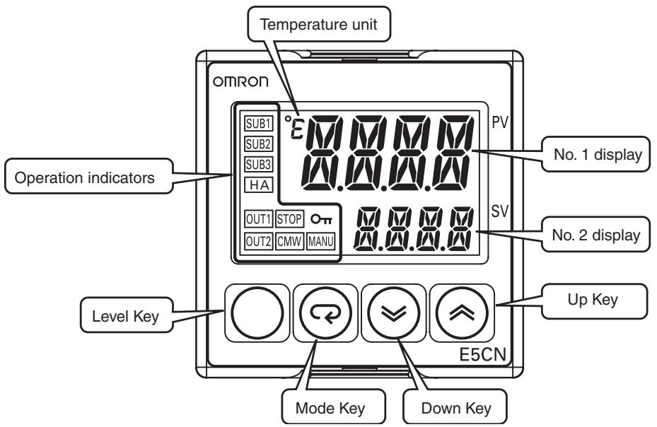
1-1-1 Front Panel
E5CN/CN-U
The front panel is the same for the E5CN and E5CN-U.
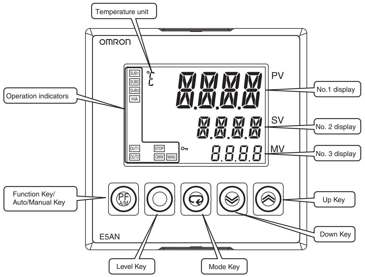
E5AN
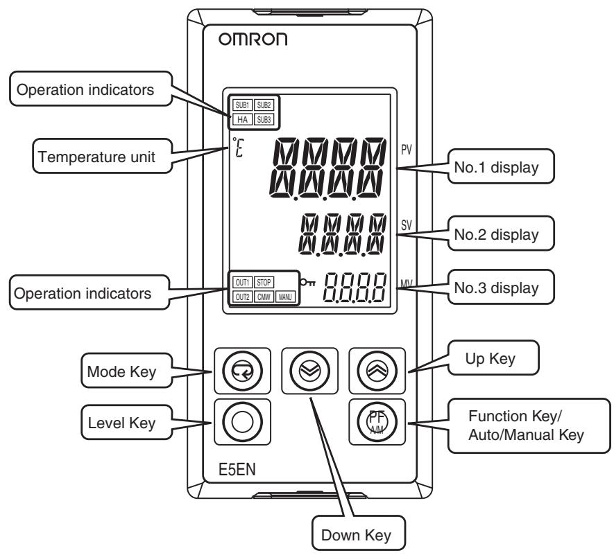
E5EN
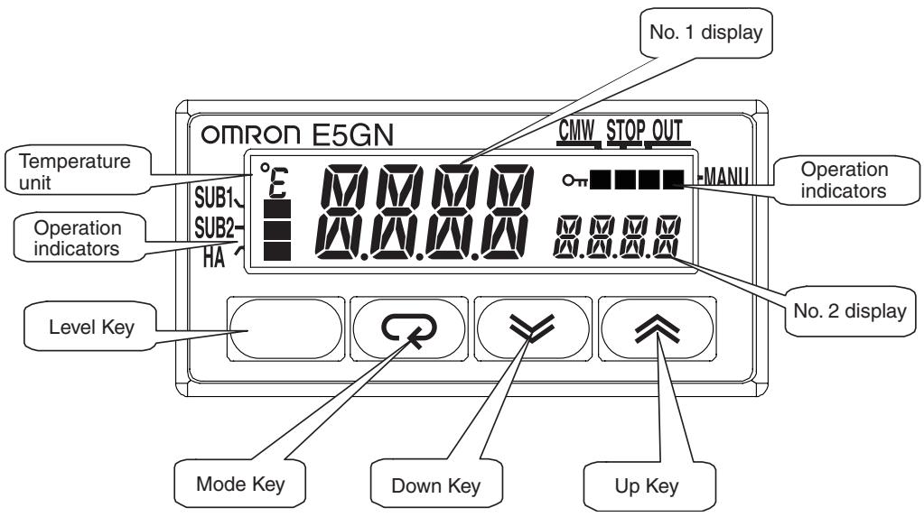
E5GN
1-1-2 Explanation of Indicators
| No. 1 Display | Displays the process value or parameter name. Lights for approximately one second during startup. |
| No. 2 Display | Displays the set point, parameter operation read value, or the variable input value. Lights for approximately one second during startup. The set point will flash during autotuning. |
| No. 3 Display (E5AN/EN Only) | Displays MV, soak time remaining, or multi SP. Lights for approximately one second during startup. A 2-level display is set when shipped from the factory. A 3-level display is activated if parameters are initialized. |
| Operation Indicators | |
| 1,2,3... | 1. SUB1 (Sub 1) Lights when the function set for the Auxiliary Output 1 Assignment parameter is ON. SUB2 (Sub 2) Lights when the function set for the Auxiliary Output 2 Assignment parameter is ON. SUB3 (Sub 3) (E5AN/EN Only) Lights when the function set for the Auxiliary Output 3 Assignment parameter is ON. 2. HA (Heater Burnout, Heater Short Alarm, Heater Overcurrent Detection Output Display) Lights when a heater burnout, heater short alarm, or heater overcurrent occurs. 3. OUT1 (Control Output 1) Lights when the control output function assigned to control output 1 turns ON. For a current output, however, OFF for a 0% output only. OUT2 (Control Output 2) (Excluding the E5GN) Lights when the control output function assigned to control output 2 turns ON. For a current output, however, OFF for a 0% output only. 4. STOP Lights when operation is stopped. During operation, this indicator lights when operation is stopped by an event or by key input using the RUN/STOP function. 5. CMW (Communications Writing) Lights when communications writing is enabled and is not lit when it is disabled. 6. MANU (Manual Mode) Lights when the auto/manual mode is set to manual mode. 7. On (Key) Lights when settings change protect is ON (i.e., when the ☑ and ☑ Keys are disabled by protected status.) |
| Temperature Unit | The temperature unit is displayed when parameters are set to display a temperature. The display is determined by the currently set value of the Temperature Unit parameter. °F indicates °C and °F indicates °F. This indicator flashes during ST operation. It is OFF on models with linear inputs. |
1-1-3 Using the Keys
PF (Function (Auto/ Manual)) Key (E5AN/EN Only)
This section describes the basic functions of the front panel keys.
This is a function key. When it is pressed for at least 1 second, the function set in the PF Setting parameter will operate.
Example: When A-M (auto/manual) is selected in the PF Setting parameter (initial value: A-M), the key operates as an auto/manual switch, switching between Auto Mode and Manual Mode. If the key is pressed for more than 1 second (regardless of key release timing), the mode will switch.
Key
Press this key to move between setting levels. The setting level is selected in the following order: operation level: adjustment level, initial setting level, communications setting level.
Key
Press this key to change parameters within a setting level.
The parameters can be reversed by holding down the key (moving one per second in reverse order).
Key
Each press of this key increments the value displayed on the No. 2 display or advances the setting. Holding the key down speeds up the incrementation.
Key
Each press of this key decrements values displayed on the No. 2 display or reverses the setting. Holding the key down speeds up the incrementation.
- Keys
Press these keys to change to the protect level. For details on operations involving holding these keys down simultaneously, refer to 1-3 Setting Level Configuration and Key Operations. For details on the protect level, refer to SECTION 5 Parameters.
O + Keys
O + Keys
To restrict set value changes (in order to prevent accidental or incorrect operations), these key operations require simultaneously pressing the key along with or key. This applies only to the parameter for the password to move to protect level. (Refer to page 162.)
1-2 I/O Configuration and Main Functions
1-2-1 I/O Configuration
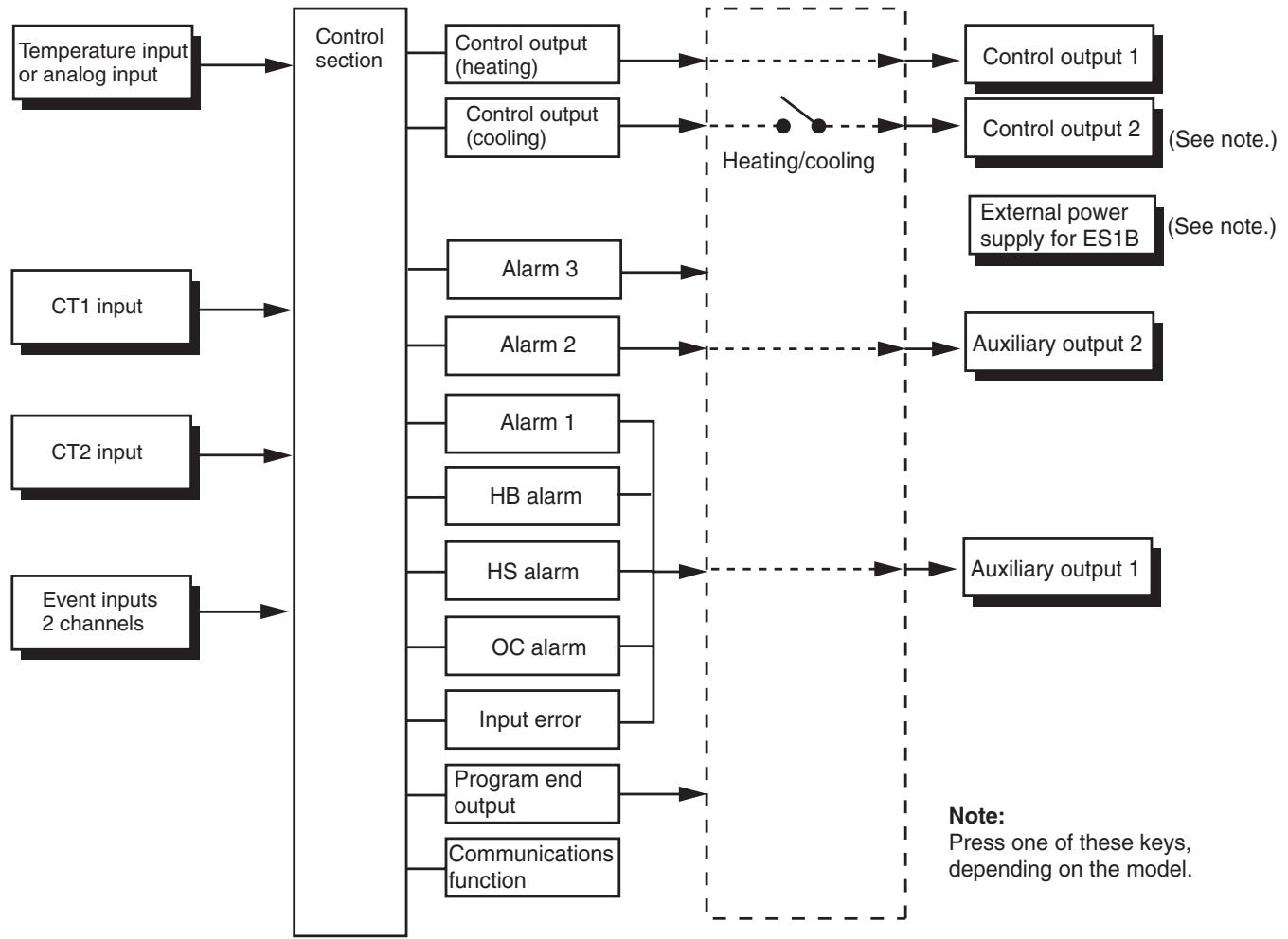
E5CN
Note
Functions can be assigned individually for each output by changing the set values for the Control Output 1 Assignment, the Control Output 2 Assignment, the Auxiliary Output 1 Assignment, and the Auxiliary Output 2 Assignment parameters in the advanced function setting level.
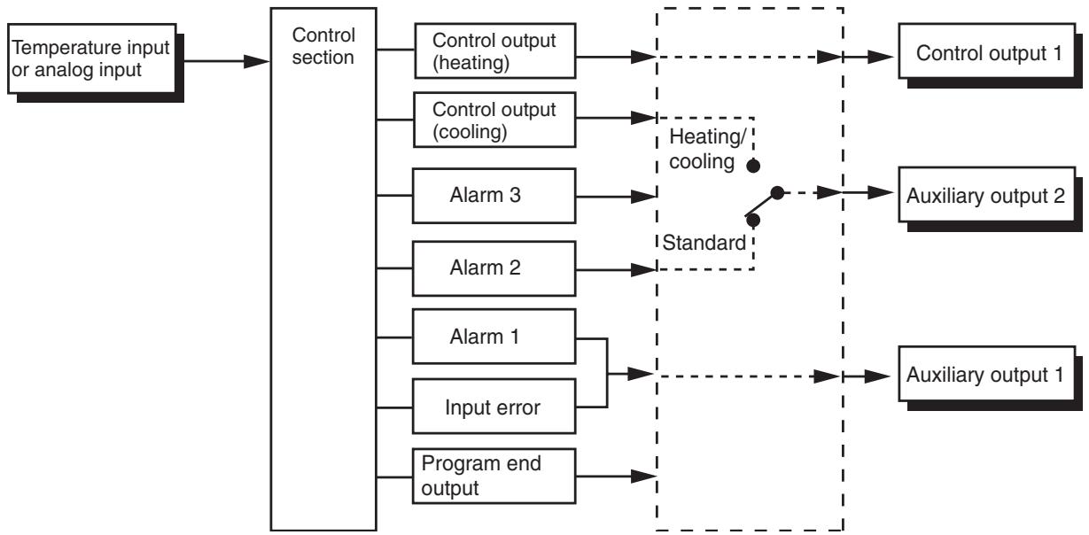
E5CN-U
Note
Functions can be assigned individually for each output by changing the set values for the Control Output 1 Assignment, the Auxiliary Output 1 Assignment, and the Auxiliary Output 2 Assignment parameters in the advanced function setting level.
Model Number Structure
Model Number Legend
Controllers
E5CN-□M□-500 1234567
1. Control Output 1
R: Relay output
Q: Voltage output (for driving SSR)
C: Current output
Y: Long-life relay output (hybrid) *1
2. Auxiliary Outputs *2
Blank: None
2: Two outputs
- Option
M: Option Unit can be mounted.
4. Input Type
T: Universal thermocouple/platinum resistance thermometer
L: Analog current/voltage input
5. Power Supply Voltage
Blank: 100 to 240 VAC
D: 24 VAC/VDC
6. Case Color
Blank: Black
W: Silver
- Terminal Cover
-500: With terminal cover
Option Units
E53-CN□□□ 1234
1. Applicable Controller
CN: E5CN or E5CN-H
2. Function 1
Blank: None
Q: Control output 2 (voltage for driving SSR)
P: Power supply for sensor
3. Function 2
Blank: None
H: Heater burnout/SSR failure/Heater overcurrent detection (CT1)
HH: Heater burnout/SSR failure/ Heater overcurrent detection (CT2)
B: Two event inputs
03: RS-485 communications
H03: Heater burnout/SSR failure/ Heater overcurrent detection (CT1) + RS-485 communications
HB: Heater burnout/SSR failure/ Heater overcurrent detection (CT1) + Two event inputs
HH03: Heater burnout/SSR failure/ Heater overcurrent detection (CT2) + RS-485 communications
4. Version
N2: Applicable only to models released after January 2008
E5CN-□U 1234
1. Output Type
R: Relay output
Q: Voltage output (for driving SSR)
C: Current output
2. Number of Alarms
Blank: No alarm
1: One alarm
2: Two alarms
3. Input Type
T: Universal thermocouple/platinum resistance thermometer
L: Analog Input
4. Plug-in type
U: Plug-in type
Note Not all combinations of function 1 and function 2 specifications are possible for Option Units (E53-□□□□).
*1 Always connect an AC load to a long-life relay output. The output will not turn OFF if a DC load is connected because a triac is used for switching the circuit. For details, check the conditions in Ratings.
*2 Auxiliary outputs are contact outputs that can be used to output alarms or results of logic operations.
E5AN/EN
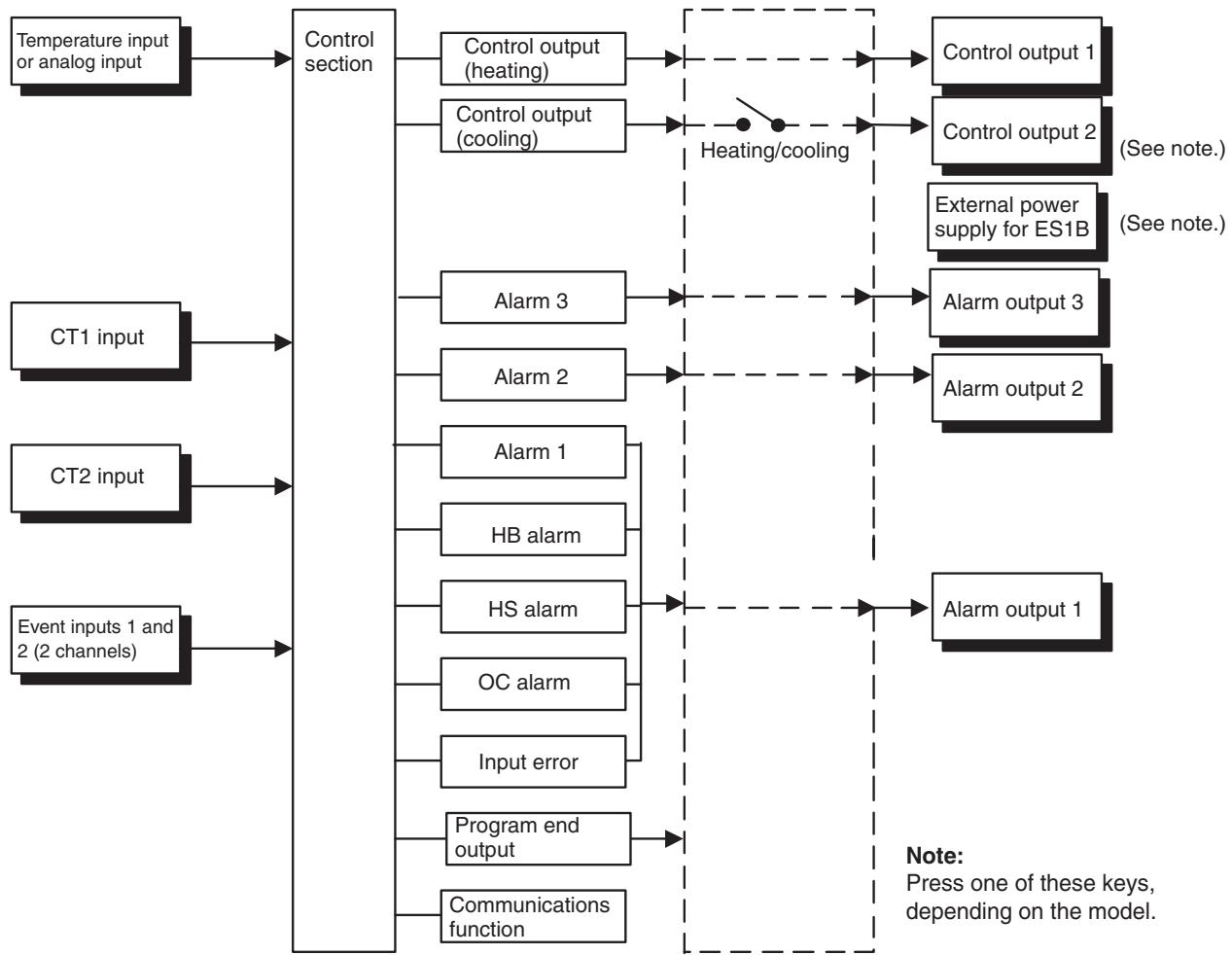
Note
Functions can be assigned individually to each output by changing the set values for the Control Output 1 Assignment, Control Output 2 Assignment, Auxiliary Output 1 Assignment, Auxiliary Output 2 Assignment, and Auxiliary Output 3 Assignment parameters in the advanced function setting level.
Model Number Structure
Model Number Legends
Controllers
E5AN/EN-3M-500-N 123456789
1. Control Output 1
R: Relay output
Q: Voltage output (for driving SSR)
C: Current output
2. Auxiliary Outputs
3: Three outputs
3. Heater Burnout/Heater Short, Control Output 2, or External Power Supply for ES1B
Blank: None
Q: Control output 2 (voltage output for driving SSR)
Y: Long-life relay output (hybrid)
H: Heater burnout/Heater short/Heater overcurrent detection (CT1)
HH: Heater burnout/Heater short/Heater overcurrent detection (CT2)
P: Power supply for sensor
4. Option
M: Option Unit can be mounted.
5. Input Type
T: Universal thermocouple/platinum resistance thermometer input
L: Analog current/voltage input
6. Power Supply Voltage
Blank: 100 to 240 VAC
D:24 VAC/VDC
7. Case Color
Blank: Black
W: Silver
8. Terminal Cover
500: With terminal cover
9. Version
N: Available only to models released after January 2008.
Option Units
1. Function
EN01: RS-232C communications
EN03: RS-485 communications
AKB: Event input
E5GN
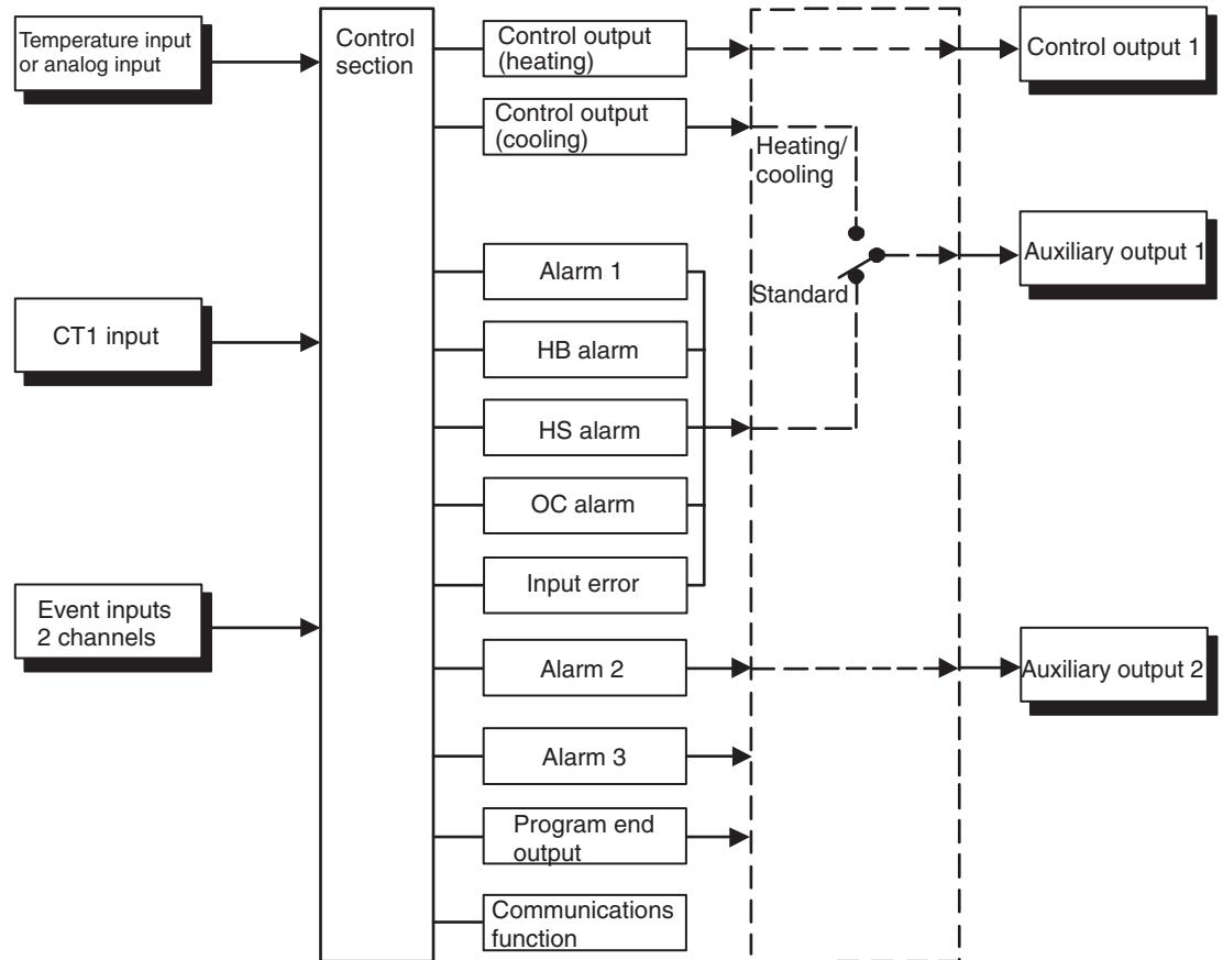
Note Functions can be assigned individually for each output by changing the set values for the Control Output 1 Assignment, the Auxiliary Output 1 Assignment, and the Auxiliary Output 2 Assignment parameters in the advanced function setting level.
Model Number Structure
Model Number Legends
Controllers
E5GN-□□□□□-□-□-□ 12345678
1. Control Output 1
R: Relay output
Q: Voltage output (for driving SSR)
C: Current output
2. Auxiliary Outputs
Blank: None
1: One outputs
2: Two outputs
3. Option
Blank: None
01: RS-232C communications
03: RS-485 communications
B: Two event inputs
H: Heater burnout/Heater short/Heater overcurrent detection (CT1)
4. Input Type
T: Universal thermocouple/platinum resistance thermometer input
L: Analog current/voltage input
5. Power Supply Voltage
Blank: 100 to 240 VAC
D:24 VAC/VDC
6. Terminal Type
Blank: Models with Screw Terminal Blocks
C: Models with Screwless Clamp Terminal Blocks
7. Case Color
Blank: Black
W: Silver
8. Communications Protocol
Blank: None
FLK: CompoWay/F communications
Note Silver is available by special order only.
1-2-2 Main Functions
This section introduces the main E5CN/CN-U/AN/EN/GN functions. For details on particular functions and how to use them, refer to SECTION 3 Basic Operation and following sections.
Input Sensor Types
- The following input sensors can be connected for temperature input (i.e., E5_N-□□□□T):
Thermocouple: K, J, T, E, L, U, N, R, S, B, W, PLII Infrared temperature sensor: ES1B
10 to 70^ , 60 to 120^ , 115 to 165^ , 140 to 260^
Platinum resistance thermometer: Pt100, JPt100
Analog input: 0 to 50mV
Control Outputs
- Inputs with the following specifications can be connected for analog input (i.e., E5_N-□□□□L):
Current input: 4 to 20mA DC, 0 to 20mA DC
Voltage input: 1 to 5 VDC, 0 to 5 V DC, 0 to 10 V DC
- A control output can be a relay, voltage (for driving SSR), or current output, depending on the model.
- Long-life relay outputs (see note) use semiconductors for switching when closing and opening the circuit, thereby reducing chattering and arcing and improving durability. However, if high levels of noise or surge are imposed between the output terminals, short-circuit faults may occasionally occur. If the output becomes permanently shorted, there is the danger of fire due to overheating of the heater. Design safety into the system, including measures to prevent excessive temperature rise and spreading of fire. Take countermeasures such as installing a surge absorber. As an additional safety measure, provide error detection in the control loop. (Use the Loop Burnout Alarm (LBA) and HS alarm that are provided for the E5□N.)
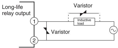
Select a surge absorber that satisfies the following conditions.
| Voltage used | Varistor voltage | Surge resistance |
| 100 to 120 VAC | 240 to 270 V | 1,000 A min. |
| 200 to 240 VAC | 440 to 470 V |
- Always connect an AC load to a long-life relay output (see note). The output will not turn OFF if a DC load is connected.
Note Long-life relay outputs are not supported for the E5GN.
Alarms
- Set the alarm type and alarm value or the alarm value upper and lower limits.
- If necessary, a more comprehensive alarm function can be achieved by setting a standby sequence, alarm hysteresis, auxiliary output close in alarm/open in alarm, alarm latch, alarm ON delay, and alarm OFF delay.
- If the Input Error Output parameter is set to ON, the output assigned to alarm 1 function will turn ON when an input error occurs.
Control Adjustment
- Optimum PID constants can be set easily by performing AT (auto-tuning) or ST (self-tuning).
Event Inputs
- With the E53-CN□B□N2 for the E5CN or the E5AN/EN-□M□-500-N with the E53-AKB for the E5AN/EN, the following functions can be executed using event inputs: switching set points (multi-SP, 4 points max.), switching RUN/STOP, switching between automatic and manual operation, starting/resetting the program, inverting direct/reverse operation, 100% AT execute/cancel, 40% AT execute/cancel, setting change enable/disable, and canceling the alarm latch.
Heater Burnout, HS Alarm, and Heater Overcurrent
- With the E53-CN□H□N2 or E53-CN□HH□N2 for the E5CN, or the E5AN/EN-□□H□-500-N or E5AN/EN-□□HH□-500-N, the heater burnout detection function, HS alarm function, and heater overcurrent detection function can be used.
| Communications Functions | ● Communications functions utilizing CompoWay/F (See note 1.), SYSWAY (See note 2.), or Modbus (See note 3.) can be used. RS-485 Interface Use the E53-CN□03N2 for the E5CN or the E53-EN03 for the E5AN/EN. RS-232C Interface Use the E53-EN01 for the E5AN/EN. |
| Note | (1) CompoWay/F is an integrated general-purpose serial communications protocol developed by OMRON. It uses commands compliant with the well-established FINS, together with a consistent frame format on OMRON Programmable Controllers to facilitate communications between personal computers and components. (2) SYSWAY communications do not support alarm 3. (3) Modbus is a communications control method conforming to the RTU Mode of Modbus Protocol. Modbus is a registered trademark of Schneider Electric. (4) The E5CN and E5CN-U do not support the RS-232C interface. |
| External Power Supply for ES1B | The E5AN-□P□-N or E5EN-□P□-N with the E53-CN□P□N2 can be used as the power supply for ES1B Infrared Temperature Sensors. |
| Note | The E5GN does not provide a power supply for an ES1B Infrared Temperature Sensor. |
| Transfer Output | A transfer output for 4 to 20 mA can be used with the E5AN/E5EN-□□F. For E5□N-C□□ models (models without “F” in the model number), the current output can be used as a simple transfer output. |
1-3 Setting Level Configuration and Key Operations
Parameters are divided into groups, each called a level. Each of the set values (setting items) in these levels is called a parameter. The parameters on the E5CN/CN-U/AN/EN/GN are divided into the following 9 levels.
When the power is turned ON, all of the display lights for approximately one second.
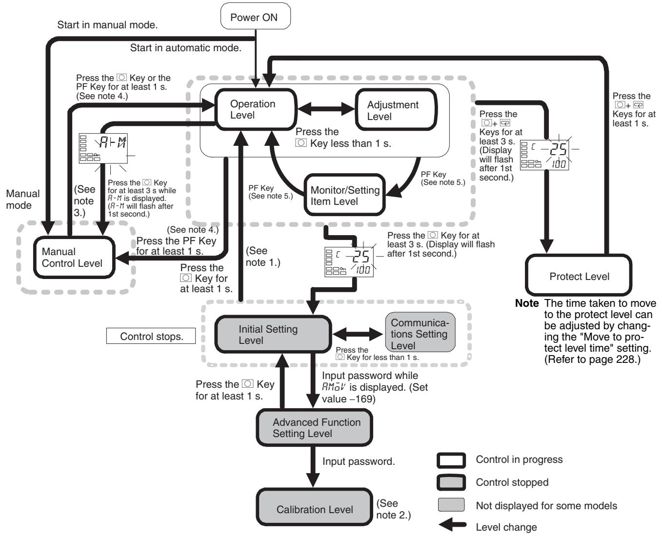
Note
(1) You can return to the operation level by executing a software reset.
(2) You cannot move to other levels by operating the keys on the front panel from the calibration level. You must turn OFF the power supply.
(3) From the manual control level, key operations can be used to move to the operation level only.
| Level | Control in progress | Control stopped |
| Protect level | Can be set. | --- |
| Operation level | Can be set. | --- |
| Adjustment level | Can be set. | --- |
| Manual control level | Can be set. | --- |
| Monitor/setting item level | Can be set. | --- |
| Initial setting level | --- | Can be set. |
| Advanced function setting level | --- | Can be set. |
| Calibration level | --- | Can be set. |
| Communications setting level | --- | Can be set. |
Of these levels, the initial setting level, communications setting level, advanced function setting level, and calibration level can be used only when control is stopped. Control outputs are stopped when any of these four levels is selected.
(4) When the PF Setting is set to A-M in models with a PF Key (E5AN/EN)
(5) When the PF Setting is set to PFDP in models with a PF Key (E5AN/EN)
Protect Level
- To switch to the protect level from the operation level, the adjustment level, or the monitor/setting item level, simultaneously hold down the and Keys for at least 3 seconds. (See note.) This level is for preventing unwanted or accidental modification of parameters. Protected levels will not be displayed, and so the parameters in that level cannot be modified.
Note The key pressing time can be changed in Move to Protect Level parameter (advanced function setting level).
Operation Level
- The operation level is displayed when the power is turned ON. You can move to the protect level, initial setting level, or adjustment level from this level.
- Normally, select this level during operation. While operation is in progress, items such as the PV and manipulated variable (MV) can be monitored, and the set points, alarm values, and alarm upper and lower limits can be monitored and changed.
Adjustment Level
- To move to the adjustment level, press the Key once (for less than 1 s).
- This level is for entering set values and offset values for control. In addition to AT (auto-tuning), communications write enable/disable switching, hysteresis settings, multi-SP settings, and input offset parameters, it includes HB alarm, HS alarm, OC alarm, and PID constants. From the adjustment level, it is possible to move to the top parameter of the initial setting level, protect level, or operation level.
Monitor/Setting Item Level
- To switch to the monitor/setting item level, press the PF Key from the operation level or adjustment level. The contents set for monitor/setting items 1 to 5 can be displayed. You can move from the monitor/setting item level to the operation level or initial setting level. (This level is supported by the E5AN and E5EN only.)
Manual Control Level
- When the Key is pressed for at least 3 seconds from the operation level's auto/manual switching display, the manual control level will be displayed. (The MANU indicator will light.)
- When the PF Setting is set to A-M (auto/manual) and the PF Key is pressed for more than one second from the operation level or adjustment level, the manual control level will be displayed (E5AN and E5EN only.)
- This is the level for changing the MV in manual mode.
- To return to the operation level, press the Key for at least one second. It is also possible to return to the operation level by pressing the PF Key for more than one second when the PF Setting is set to A-M.
Initial Setting Level
- To move to the initial setting level from the operation level or the adjustment level, press the Key for at least 3 seconds. The PV display flashes after one second. This level is for specifying the input type and selecting the control method, control period, setting direct/reverse operation, setting the alarm types, etc. You can move to the advanced function setting level or communications setting level from this level. To return to the operation level, press the Key for at least one second. To move to the communications setting level, press the Key for less than one second.
(When moving from the initial setting level to the operation level, all the indicators will light.)
Note Pressing the Key for at least 3 seconds in the operation level's auto/manual switching display will move to the manual control level, and not the initial setting level.
Advanced Function Setting Level
- To move to the advanced function setting level, set the Initial Setting/Communications Protect parameter in the protect level to 0 and then, in the initial setting level, input the password (-169).
- From the advanced function setting level, it is possible to move to the calibration level or to the initial setting level.
- This level is for setting the automatic display return time and standby sequence, and it is the level for moving to the user calibration and other functions.
Communications Setting Level
- To move to the communications setting level from the initial setting level, press the Key once (for less than 1 s). When using the communications function, set the communications conditions in this level. Communicating with a personal computer (host computer) allows set points to be read and written, and manipulated variables (MV) to be monitored.
Calibration Level
- To move to the calibration level, input the password (1201) from the advanced function setting level. The calibration level is for offsetting error in the input circuit.
- You cannot move to other levels from the calibration level by operating the keys on the front panel. To cancel this level, turn the power OFF then back ON again.
1-3-1 Selecting Parameters
- Within each level, the parameter is changed in order (or in reverse order) each time the l Key is pressed. (In the calibration level, however, parameters cannot be changed in reverse order.) For details, refer to SECTION 5 Parameters.
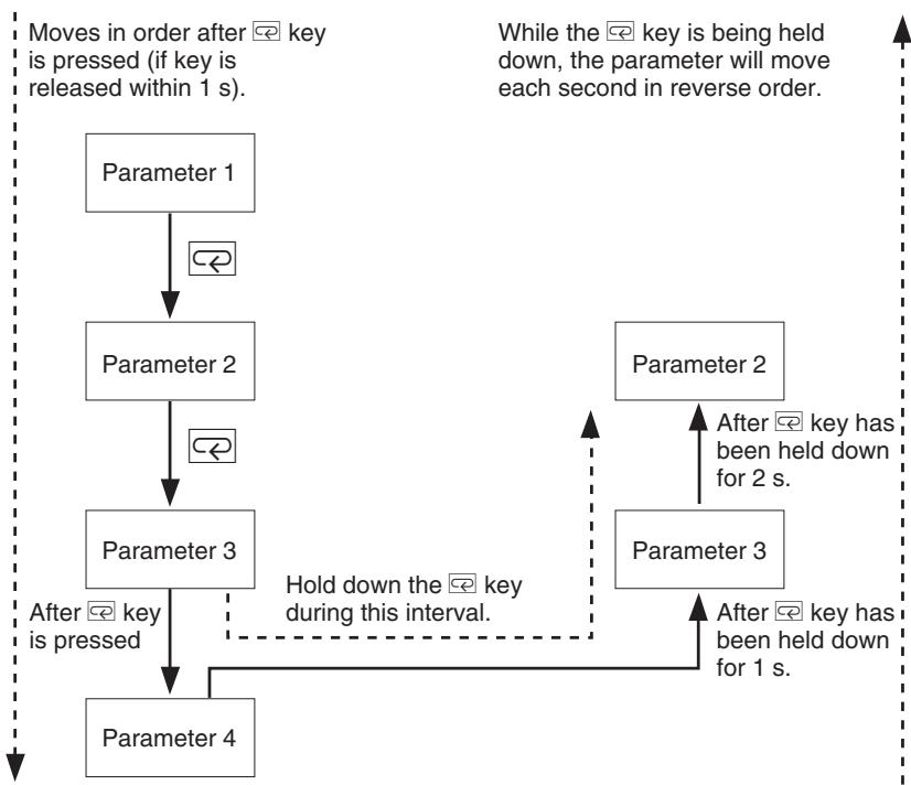
1-3-2 Saving Settings
- If you press the Key at the final parameter, the display returns to the top parameter for the current level.
- To change parameter settings, specify the setting using the or Key, and either leave the setting for at least two seconds or press the Key. This saves the setting.
- When another level is selected after a setting has been changed, the contents of the parameter prior to the change is saved.
- When you turn the power OFF, you must first save the settings (by pressing the Key). The settings are sometimes not changed by merely pressing the or Keys.
1-4 Communications Function
The E5CN/AN/EN/GN are provided with a communications function that enables parameters to be checked and set from a host computer. If the communications function is required, use the E53-CN□03N2 with the E5CN, or the E53-EN03 or E53-EN01 with the E5AN/EN/GN. For details on the communications function, see the separate Communications Manual Basic Type. Use the following procedure to move to the communications setting level.
1,2,3... 1. Press the Key for at least three seconds to move from the operation level to the initial setting level.
2. Press the Key for less than one second to move from the initial setting level to the communications setting level.
3. Select the parameters as shown below by pressing the Key.
4. Press the or Key to change the parameter setting.
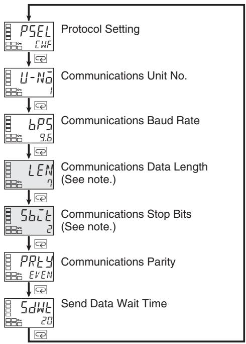
Note The Protocol Setting parameter is displayed only when CompoWay/F communications are being used.
Setting Communications Data
Match the communications specifications of the E5CN/AN/EN/GN and the host computer. If a 1:N connection is being used, ensure that the communications specifications for all devices in the system (except the communications Unit No.) are the same.
| Parameter name | Symbol | Setting (monitor) value | Selection symbols | Default | Unit |
| Protocol Setting | PSEL | CompoWay/F (SYSWAY), Modbus | EWF, Mad | CompoWay/F (SYSWAY) | None |
| Communications Unit No. | U-NO | 0 to 99 | 1 | None | |
| Communications Baud Rate | bPS | 1.2, 2.4, 4.8, 9.6, 19.2, 38.4, 57.6 | 1.2, 2.4, 4.8, 9.6, 19.2, 38.4, 57.6 | 9.6 | kbps |
| Communications Data Length | LEN | 7, 8 | 7 | Bits | |
| Communications Stop Bits | SbCT | 1, 2 | 2 | Bits | |
| Communications Parity | PREY | None, Even, Odd | None, Even, add | Even | None |
| Send Data Wait Time | SdWE | 0 to 99 | 20 | ms |
1-5 Insulation Block Diagrams
The insulation block diagrams for the E5CN, E5AN, E5EN, and E5GN are provided in this section.
E5CN
| Power supply | Input, CT input, Q outputs (outputs 1 and 2) |
| Communications and events | |
| External power supply | |
| C output | |
| R output | |
| Y output | |
| Auxiliary outputs 1 and 2 |
E5CN-U
: Reinforced insulation : Functional insulation
| Power supply | Input and Q output (output 1) |
| C output | |
| R output | |
| Y output | |
| Auxiliary outputs 1 and 2 |
E5AN/EN
: Reinforced insulation : Functional insulation
| Power supply | Input, CT input, and Q output (output 1) |
| Communications and events | |
| External power supply and Q output (output 2) | |
| C output and transfer output | |
| R output | |
| Y output | |
| Auxiliary output 1 | |
| Auxiliary output 2 | |
| Auxiliary output 3 |
E5GN
: Reinforced insulation : Functional insulation
| Power supply | Input, CT input, Q output (output 1) |
| Communications and events | |
| C output | |
| R output | |
| Auxiliary output 1 | |
| Auxiliary output 2 |
: Reinforced insulation : Functional insulation
SECTION 2 Preparations
This section describes the work required to prepare the E5CN, E5AN, and E5EN Digital Temperature Controllers for operation, including installation and wiring.
2-1 Installation. 22
2-1-1 Dimensions 22
2-1-2 Panel Cutout 24
2-1-3 Mounting. 25
2-1-4 Removing the Temperature Controller from the Case 28
2-2 Wiring Terminals. 31
2-2-1 Terminal Arrangement 31
2-2-2 Precautions when Wiring 33
2-2-3 Wiring. 35
2-3 Using the Support Software Port. 45
2-1 Installation
2-1-1 Dimensions
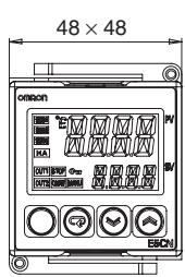
Unit: mm
E5CN
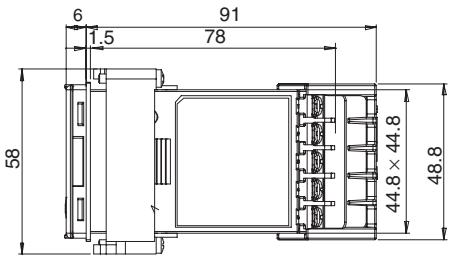
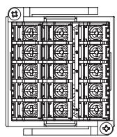
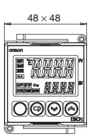
E5CN-U
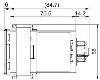
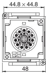
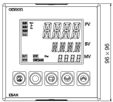
E5AN
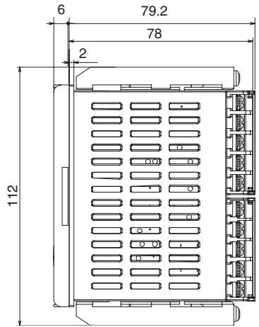
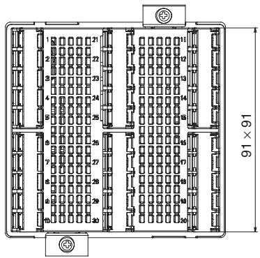
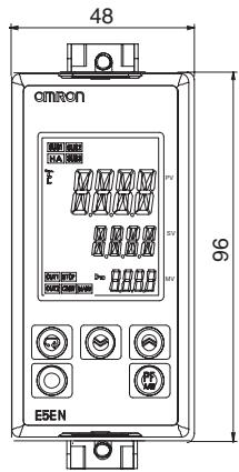
E5EN
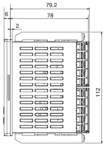
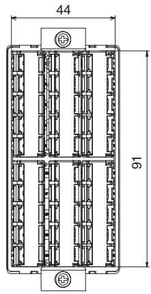
E5GN
- Models with Screw Terminal Blocks
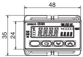

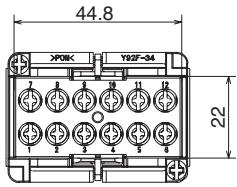
- Models with Screwless Clamp Terminal Blocks
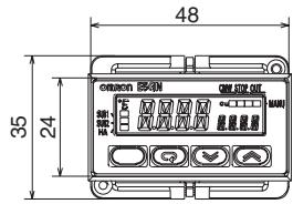
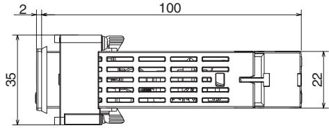
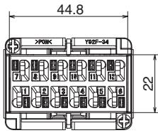
2-1-2 Panel Cutout
Unit: mm
E5CN/CN-U
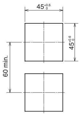
Individual Mounting
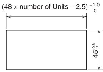
Group Mounting
E5AN
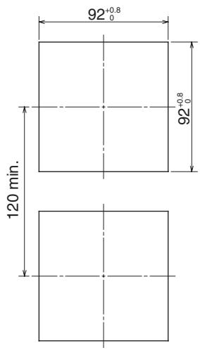
Individual Mounting
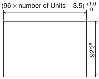
Group Mounting
E5EN

Individual Mounting
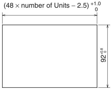
Group Mounting
E5GN
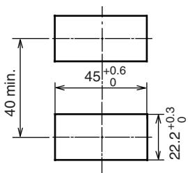
Individual Mounting
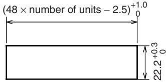
Group Mounting
- Waterproofing is not possible when group mounting several Controllers.
- The recommended panel thickness is 1 to 5mm for the E5CN, E5CN-U, and E5GN, and 1 to 8mm for E5AN and E5EN.
- Units must not be closely mounted vertically. (Observe the recommended mounting space limits.)
- When group mounting several Controllers, ensure that the surrounding temperature does not exceed the ambient operating temperature listed in the specifications.
2-1-3 Mounting
E5CN/CN-U
E53-COV17
Terminal Cover
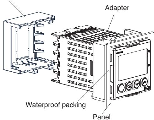
E5CN
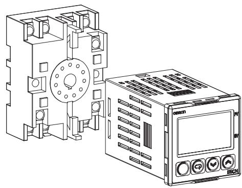
E5CN-U
For the Wiring Socket for the E5CN-U, order the P2CF-11 or P3GA-11 separately.
Mounting to the Panel
1,2,3...
- For waterproof mounting, waterproof packing must be installed on the Controller. Waterproofing is not possible when group mounting several Controllers. Waterproof packing is not necessary when there is no need for the waterproofing function. There is no waterproof packing included with the E5CN-U.
- Insert the E5CN/E5CN-U into the mounting hole in the panel.
- Push the adapter from the terminals up to the panel, and temporarily fasten the E5CN/E5CN-U.
- Tighten the two fastening screws on the adapter. Alternately tighten the two screws little by little to maintain a balance. Tighten the screws to a torque of 0.29 to 0.39N· m .
Mounting the Terminal Cover
For the E5CN, make sure that the "UP" mark is facing up, and then attach the E53-COV17 Terminal Cover to the holes on the top and bottom of the Temperature Controller.
E5AN/EN

E5AN
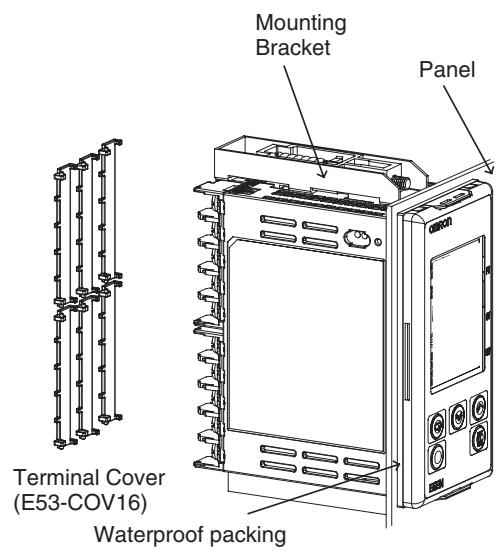
E5EN
Mounting to the Panel
1,2,3...
- For waterproof mounting, waterproof packing must be installed on the Controller. Waterproofing is not possible when group mounting several Controllers. Waterproof packing is not necessary when there is no need for the waterproofing function.
- Insert the E5AN/E5EN into the square mounting hole in the panel (thickness: 1 to 8mm ). Attach the Mounting Brackets provided with the product to the mounting grooves on the top and bottom surfaces of the rear case.
- Use a ratchet to alternately tighten the screws on the top and bottom Mounting Brackets little by little to maintain balance, until the ratchet turns freely.
Mounting the Terminal Cover
Slightly bend the E53-COV16 Terminal Cover to attach it to the terminal block as shown in the following diagram. The Terminal Cover cannot be attached in the opposite direction.
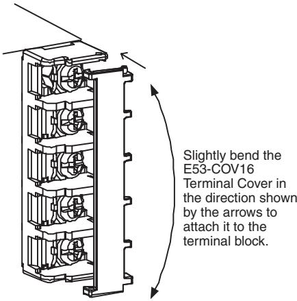
Enlarged Illustration of Terminal Section
E5GN
Mounting to the Panel
1,2,3...
- For waterproof mounting, waterproof packing must be installed on the Controller. Waterproofing is not possible when group mounting several Controllers.
Waterproof packing is not necessary when there is no need for the waterproofing function. - Insert the E5GN into the mounting hole in the panel.
- Push the adapter from the terminals up to the panel, and temporarily fasten the E5GN.
- Tighten the two fastening screws on the adapter. Alternately tighten the two screws little by little to maintain a balance. Tighten the screws to a torque of 0.29 to 0.39N· m .
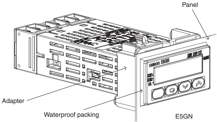
2-1-4 Removing the Temperature Controller from the Case
The Temperature Controller can be removed from the case to perform maintenance without removing the terminal leads. This is possible for only the E5CN, E5AN, and E5EN, and not for the E5CN-U or E5GN. Check the specifications of the case and Temperature Controller before removing the Temperature Controller from the case.
E5CN
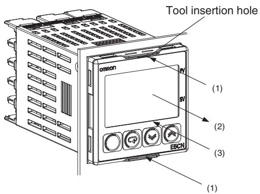
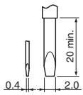
Flat-blade screwdriver (Unit: mm)
1,2,3...
- Insert a flat-blade screwdriver into the two tool insertion holes (one on the top and one on the bottom) to release the hooks.
- Insert the flat-blade screwdriver in the gap between the front panel and rear case, and pull out the front panel slightly. Hold the top and bottom of the front panel and carefully pull it out toward you, without applying unnecessary force.
- When inserting the body of the Temperature Controller into the case, make sure the PCBs are parallel to each other, make sure that the sealing rubber is in place, and press the E5CN toward the rear case into position. While pushing the E5CN into place, push down on the hooks on the top and bottom surfaces of the rear case so that the hooks are securely locked in place. Be sure that electronic components do not come into contact with the case.
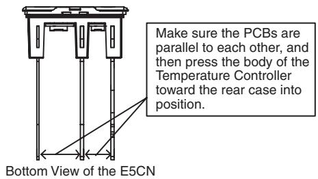
E5AN/EN
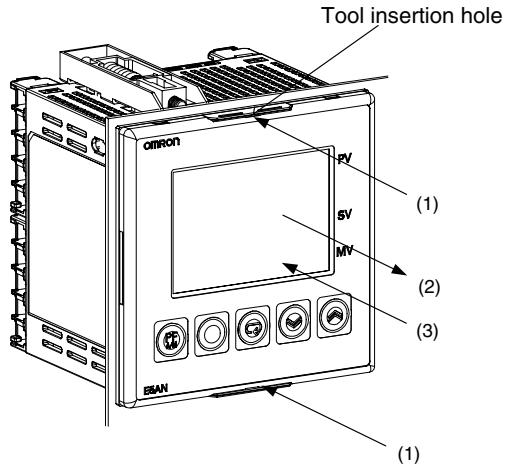
E5AN
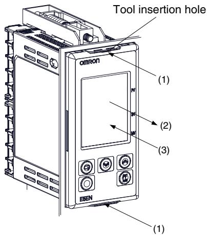
E5EN
Flat-blade screwdriver (Unit: mm)
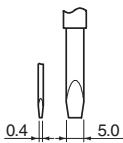
1,2,3...
- Insert a flat-blade screwdriver into the two tool insertion holes (one on the top and one on the bottom) to release the hooks.
- Insert the flat-blade screwdriver in the gap between the front panel and rear case (two on the top and two on the bottom), and use it to pry and pull out the front panel slightly. Then, pull out on the front panel gripping both sides. Be sure not to impose excessive force on the panel.
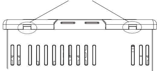
Gap between the Front Panel and Rear Case Four gaps, two on the top and two on the bottom
Top View of E5AN
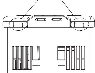
Gap between the Front Panel and Rear Case Four gaps, two on the top and two on the bottom
Top View of E5EN
- When inserting the body of the Temperature Controller into the case, make sure the PCBs are parallel to each other, make sure that the sealing rubber is in place, and press the E5AN/EN toward the rear case until it snaps into position. While pressing the E5AN/EN into place, press down on the hooks on the top and bottom surfaces of the rear case so that the hooks securely lock in place. Make sure that electronic components do not come into contact with the case.
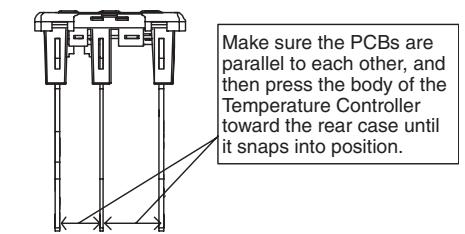
Bottom View of the E5EN

Bottom View of the E5AN
Removing the Terminal Block
E5GN
The terminal block can be removed from the E5GN. It is not possible for the E5CN, E5AN, E5EN, and E5CN-U.
The body of the Controller can be replaced by removing the terminal block from the E5GN.
1,2,3...
- Insert a flat-blade screwdriver into the tool holes (one on the top and one on the bottom) to release the hooks. Do not apply excessive force.

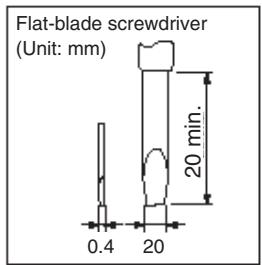
2. Pull the terminal block out while the hooks are released.
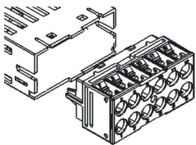
Note
The method for removing the terminal block is the same for both screw terminal blocks and screwless clamp terminal blocks.
Do not connect a different type of terminal block to a Controller. For example, do not replace a screw terminal block with a screwless clamp terminal block. The temperature indication accuracy will decrease.
2-2 Wiring Terminals
Confirm the location of the terminals (terminals 1 to 15 for the E5CN, 1 to 30 for the E5AN and E5EN, and terminals 1 to 14 for the E5GN) using the product labels and case markings.
2-2-1 Terminal Arrangement
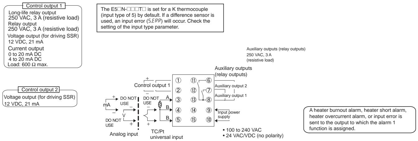
E5CN Controllers
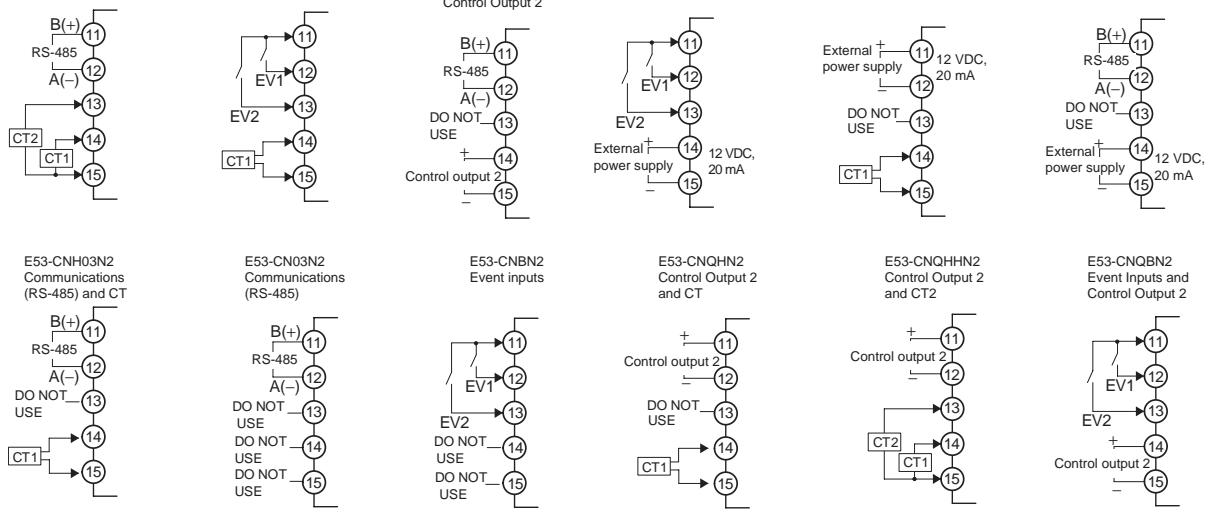
Option Units E53-CNHH03N2 Communications (RS-485) and CT2
Since the voltage output (control output) is not electrically insulated from the internal wiring, one or other of the control output terminals must be left unearthed when using an earthed thermocouple thermometer. (Connection makes measurements unreliable due to sneak currents.)
To comply with EMC standards, the length of the cable connecting the analog input or universal TC/Pt input sensor must be 30m or less. If the cable is longer than 30m , the EMC standards will not be satisfied.
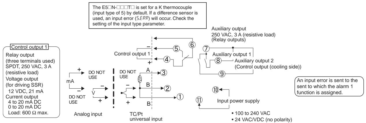
E5CN-U
Note For the Wiring Socket, purchase the P2CF-11 or PG3A-11 separately.
Since the voltage output (control output) is not electrically insulated from the internal wiring, one or other of the control output terminals must be left unearthed when using an earthed thermocouple thermometer. (Connection makes measurements unreliable due to sneak currents.)
To comply with EMC standards, the length of the cable connecting the analog input or universal TC/Pt input sensor must be 30m or less. If the cable is longer than 30m , the EMC standards will not be satisfied.
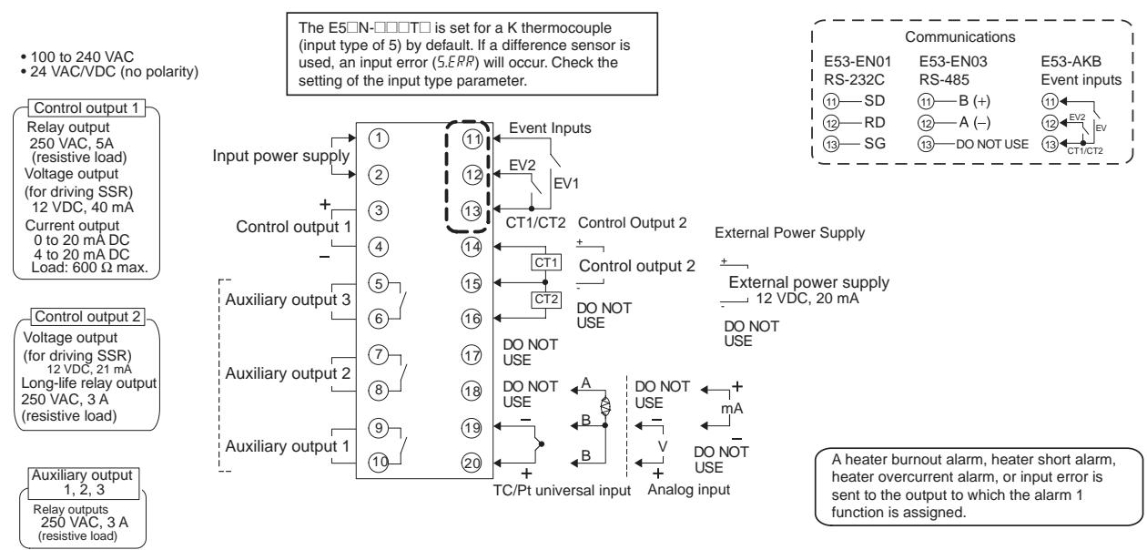
E5AN/EN Controllers
Since the voltage output (control output) is not electrically insulated from the internal wiring, one or other of the control output terminals must be left unearthed when using an earthed thermocouple thermometer. (Connection makes measurements unreliable due to sneak currents.)
To comply with EMC standards, the length of the cable connecting the analog input or universal TC/Pt input sensor must be 30m or less. If the cable is longer than 30m , the EMC standards will not be satisfied.
E5GN
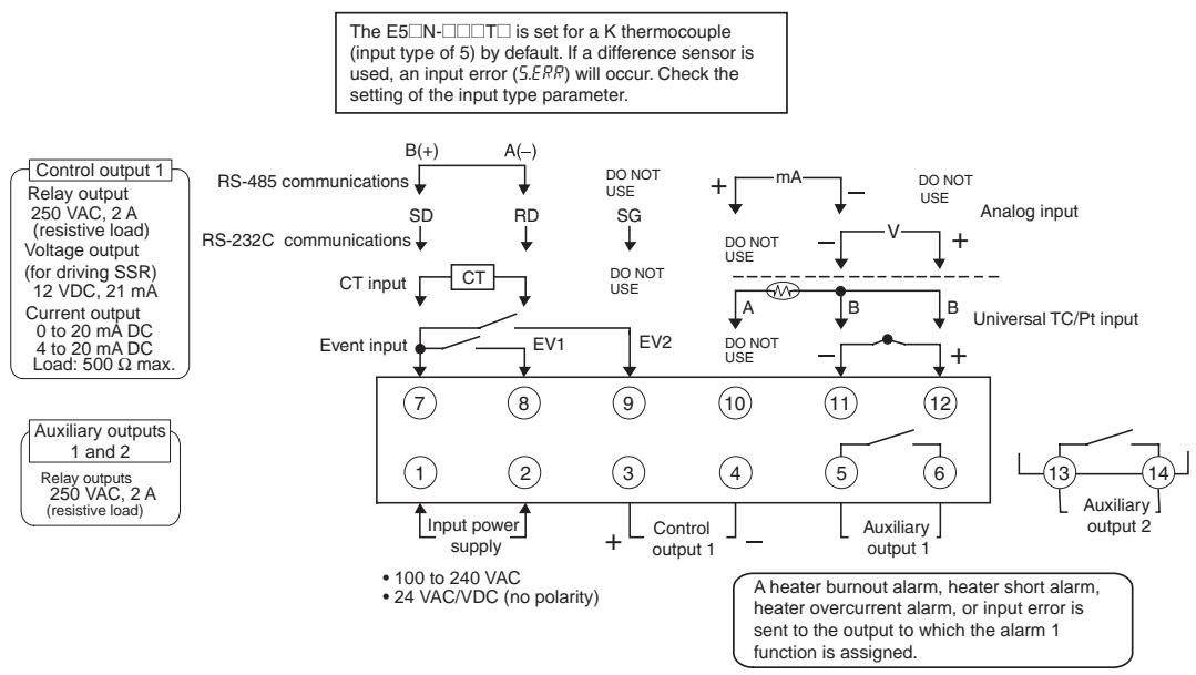
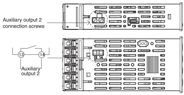
Since the voltage output (control output) is not electrically insulated from the internal wiring, one or other of the control output terminals must be left unearthed when using an earthed thermocouple thermometer. (Connection makes measurements unreliable due to sneak currents.)
To comply with EMC standards, the length of the cable connecting the analog input or universal TC/Pt input sensor must be 30m or less. If the cable is longer than 30m , the EMC standards will not be satisfied.
2-2-2 Precautions when Wiring
- Separate input leads and power lines in order to prevent external noise.
- Use a shielded, AWG24 to AWG14 (cross-sectional area of 0.205 to 2.081 ~mm^2 ) twisted-pair cable for the E5CN, E5EN, or E5AN. Use a shielded, AWG24 to AWG18 (cross-sectional area of 0.205 to 0.823 ~mm^2 ) twisted-pair cable for the E5GN. The stripping length is 5 to 6 mm for the E5CN, E5AN, or E5EN, and 6 to 8 mm for the E5GN.
- Use crimp terminals when wiring the terminals.
- Use the suitable wiring material and crimp tools for crimp terminals.
- Tighten the terminal screws to a torque of 0.5N· m for the E5CN-U and E5GN and to 0.74 to 0.90N· m for other models. The terminal torque is 0.5 to 0.6N· m for auxiliary output 2 on the E5GN.
- For the E5CN, E5AN, or E5EN, use the following types of crimp terminals for M3.5 screws.
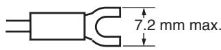
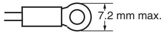
- For the E5GN, use the following types of crimp terminals for M3.0 screws.
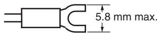
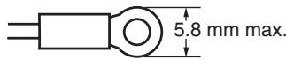
- For E5GN screwless clamp terminal blocks, use wires with a gauge of AWG24 to AWG18 (equal to a cross-sectional area of 0.205 to 0.823 ~mm^2 ). The length of the conductive portion inserted into the terminal must be 10 ~mm for wires and 8 to 12 ~mm for ferrules. Ferrules must be 0.8 to 1.4 ~mm in diameter.
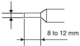
0.8 to 1.4mm
Ferrules
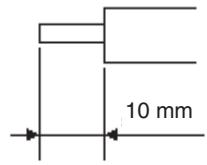
wires
- Recommended Ferrules for E5GN Screwless Clamp Terminals
| Manufacturer | Model number | |
| Altech Corp. | 2623.0 | |
| Daido Solderless Terminal Mfg. Co. | AVA-0.5 | |
| J.S.T. Mfg. Co. | TUB-0.5 | |
| Nichifu Co. | Single (1 wire) | TGNTC-1.25-9T TGVTC-1.25-11T TGNTC-1.25-11T TC0.3-9.5 TC1.25-11S-ST TC1.25-11S TC2-11S |
| Double (2 wires) | TGWVTC-1.25-9T TGWVTC-1.25-11T | |
- Use wires with a gauge of AWG24 to AWG18 (0.205 to 0.823 mm²) for auxiliary output 2 on the E5GN.
The exposed conductor length inserted into the terminal for wires or ferrules must be 6mm . Ferrules must be 0.8 to 1.5mm in diameter.
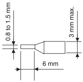
Ferrules
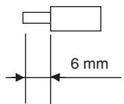
Wires
- Recommended Ferrules for SUB2 on E5GN
| Manufacturer | Model number |
| Phoenix Contact | AI 0,25-6 BU |
| AI 0,34-6 TQ | |
| AI 0,5-6 WH | |
| AI 0,75-6 GY | |
| AI 1-6 RD |
Note Do not remove the terminal block from the E5AN, E5EN, or E5CN. Doing so may cause product malfunction or incorrect operation.
2-2-3 Wiring
Power supply
In the connection diagrams, the left side of the terminal numbers represents the inside of the Controller and the right side represents the outside.
- With the E5CN, connect to terminals 9 and 10; with the E5CN-U, connect to pins 10 and 11; with the E5AN, E5EN, and E5GN, connect pins 1 and 2. The following table shows the specifications.
| Input power supply | E5CN | E5CN-U | E5AN/EN | E5GN |
| 100 to 240 VAC, 50/60 Hz | 7.5 VA | 6 VA | 10 VA | 5.5 VA |
| 24 VAC, 50/60 Hz | 5 VA | 3 VA | 5.5 VA | 3 VA |
| 24 VDC (no polarity) | 3 W | 2 W | 4 W | 2 W |
- These models have reinforced insulation between the input power supply, the relay outputs, and other terminals.
Input
- Make the connections according to the input type as shown below, using terminals 3 to 5 for the E5CN, pins 1 to 3 for the E5CN-U, pins 18 to 20 for the E5AN or E5EN and pins 10 to 12 for the E5GN.
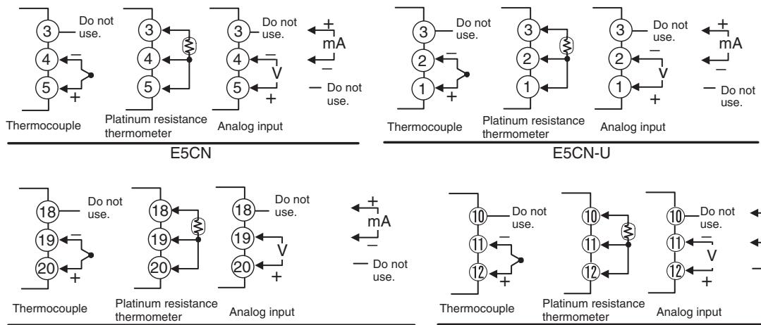
E5AN/EN
E5GN
When extending the thermocouple lead wires, be sure to use compensating wires that match the thermocouple type. When extending the lead wires of a platinum resistance thermometer, be sure to use wires that have low resistance and keep the resistance of the three lead wires the same.
Control Output 1
- Outputs are sent from terminals 1 and 2 with the E5CN, from pins 4 to 6 with the E5CN-U, and from pins 3 and 4 with the E5AN/EN/GN. The following diagrams show the available outputs and their internal equalizing circuits.
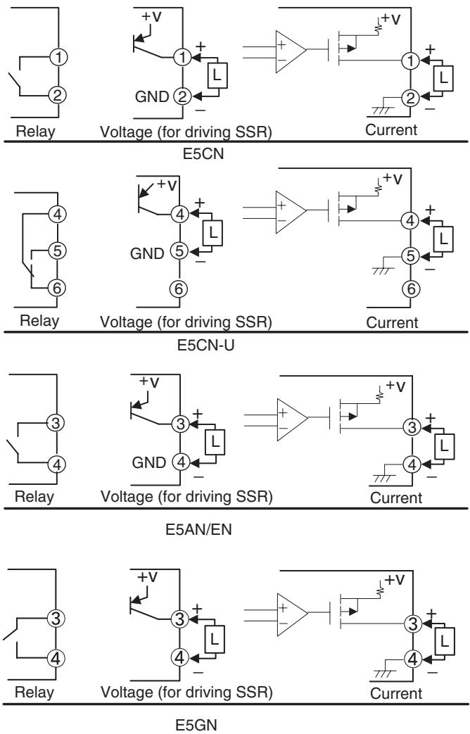
- The following table shows the specifications for each output type.
E5CN/CN-U
| Output type | Specifications |
| Relay | 250 VAC, 3 A (resistive load), electrical durability: 100,000 operations |
| Long-life relay (using a triac) | 250 VAC, 3 A (resistive load), electrical durability: 1,000,000 operations |
| Voltage (for driving SSR) | PNP type, 12 VDC ±15%, 21 mA (with short-circuit protection) |
| Current | DC 4 to 20 mA/DC 0 to 20 mA, resistive load: 600 Ω max. Resolution: Approx. 10,000 |
E5AN/EN
| Output type | Specifications |
| Relay | 250 VAC, 5 A (resistive load), electrical durability: 100,000 operations |
| Voltage (for driving SSR) | PNP type, 12 VDC +15%, 40 mA (with short-circuit protection) |
| Current | DC 4 to 20 mA/DC 0 to 20 mA, resistive load: 600 Ω max. Resolution: Approx. 10,000 |
E5GN
| Output type | Specifications |
| Relay | 250 VAC, 2 A (resistive load), electrical durability: 100,000 operations |
| Voltage (for driving SSR) | PNP type, 12 VDC ±15%, 21 mA (with short-circuit protection) |
| Current | DC 4 to 20 mA/DC 0 to 20 mA, resistive load: 500 Ω max. Resolution: Approx. 10,000 |
- Always connect an AC load to a long-life relay output. The output will not turn OFF if a DC load is connected.
- The voltage output (for driving SSR) is not electrically isolated from the internal circuits. When using a grounding thermocouple, do not connect any of the control output terminals to the ground. If a control output terminal is connected to the ground, errors will occur in the measured temperature as a result of leakage current.
- Control output 1 (voltage output for driving SSR) and control output 2 (voltage output for driving SSR) are not isolated. For the E5AN/EN, however, the internal circuits are functionally isolated.
- Long-life relay outputs use semiconductors for switching when closing and opening the circuit, thereby reducing chattering and arcing and improving durability. However, if high levels of noise or surge are imposed between the output terminals, short-circuit faults may occasionally occur. If the output becomes permanently shorted, there is the danger of fire due to overheating of the heater. Design safety into the system, including measures to prevent excessive temperature rise and spreading of fire.
- Take countermeasures such as installing a surge absorber. As an additional safety measure, provide error detection in the control loop. (Use the Loop Burnout Alarm (LBA) and HS alarm that are provided for the E5☐N.)
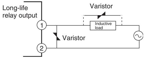
Select a surge absorber that satisfies the following conditions.
| Voltage used | Varistor voltage | Surge resistance |
| 100 to 120 VAC | 240 to 270 V | 1,000 A min. |
| 200 to 240 VAC | 440 to 470 V |
Control Output 2
- Outputs are sent from terminals 11, 12, 14, and 15 with the E5CN, and from pins 14 and 15 with the E5AN/EN. The following diagrams show the available outputs and their internal equalizing circuits.
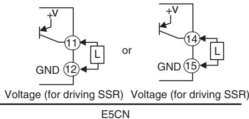
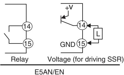
- The following table shows the specifications for each output type.
E5CN
| Output type | Specifications |
| Voltage (for driving SSR) | PNP type, 12 VDC ±15%, 21 mA (with short-circuit protection) |
E5AN/EN
| Output type | Specifications |
| Long-life relay (using a triac) | 250 VAC, 3 A (resistive load), electrical durability: 1,000,000 operations |
| Voltage (for driving SSR) | PNP type, 12 VDC ±15%, 21 mA (with short-circuit protection) |
- Always connect an AC load to a long-life relay output. The output will not turn OFF if a DC load is connected.
- The voltage output (for driving SSR) is not electrically isolated from the internal circuits. Therefore, when using a grounding thermocouple, do not connect any of the control output terminals to the ground. If a control output terminal is connected to the ground, errors will occur in the measured temperature as a result of leakage current. With E5AN/EN, however, control output 2 (voltage output for driving SSR) is functionally isolated from the internal circuits.
- Control output 2 of the E5CN is a voltage output (for driving SSR) only, and outputs across terminals 11(+) and 12(-) , or 14(+) and 15(-) .
- Control output 1 (voltage output for driving SSR) and control output 2 (voltage output for driving SSR) are not isolated.
-
Long-life relay outputs use semiconductors for switching when closing and opening the circuit, thereby reducing chattering and arcing and improving durability. However, if high levels of noise or surge are imposed between the output terminals, short-circuit faults may occasionally occur. If the output becomes permanently shorted, there is the danger of fire due to overheating of the heater. Design safety into the system, including measures to prevent excessive temperature rise and spreading of fire.
-
Take countermeasures such as installing a surge absorber. As an additional safety measure, provide error detection in the control loop. (Use the Loop Burnout Alarm (LBA) and HS alarm that are provided for the E5□N.)
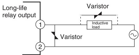
Select a surge absorber that satisfies the following conditions.
| Voltage used | Varistor voltage | Surge resistance |
| 100 to 120 VAC | 240 to 270 V | 1,000 A min. |
| 200 to 240 VAC | 440 to 470 V |
Auxiliary Outputs 1, 2, and 3
- On the E5CN- 2 □, auxiliary output 1 (SUB1) is output across terminals 7 and 8, and auxiliary output 2 (SUB2) is output across terminals 6 and 8.
- On the E5CN- 1 U, auxiliary output 1 (SUB1) is output across terminals 7 and 8.
- On the E5CN-□2□□U, auxiliary output 1 (SUB1) is output across terminals 7 and 8, and auxiliary output 2 (SUB2) is output across terminals 7 and 9.
- On the E5AN/EN-□3□□□, auxiliary output 1 (SUB1) is output across terminals 9 and 10, auxiliary output 2 (SUB2) is output across terminals 7 and 8, and auxiliary output 3 (SUB3) is output across terminals 5 and 6.
- On the E5GN-□2□□□, auxiliary output 1 (SUB1) is output across terminals 5 and 6, and auxiliary output 2 (SUB2) is output across terminals 13 and 14 on the bottom of the Controller. Wire terminals 13 and 14 and tighten the screws.
- When the Input Error Output parameter is set to ON, the output assigned to the alarm 1 function turns ON when an input error occurs.
- When the HB alarm, HS alarm, or heater overcurrent alarm is used with the E5CN-□□H□, E5CN-□□HH□, or E5GN-□□H□, alarms are output to the output assigned to the alarm 1 function.
- When the HB alarm, HS alarm, or heater overcurrent alarm is used with the E5AN/EN-□□H□□, alarms are output to the output assigned to the alarm 1 function.
- On the E5CN and E5CN-U, when heating/cooling control is used, auxiliary output 2 becomes control output (cooling).
- On the E5AN and E5EN, when heating/cooling control is used, auxiliary output 3 becomes control output (cooling).
- On the E5GN, when heating/cooling control is used, auxiliary output 1 becomes control output (cooling).
- For models that have a heater burnout alarm, an OR of the alarm 1 function and the HB alarm, HS alarm, or heater overcurrent alarm is sent to the output assigned to the alarm 1 function (auxiliary output 1). If the alarm 1 function is to be used for HB alarm only, set the alarm 1 type to 0 (i.e., do not use alarm 1 function).
- The following diagrams show the internal equalizing circuits for auxiliary outputs 1, 2, and 3.
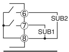
E5CN
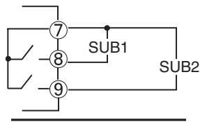
E5CN-U
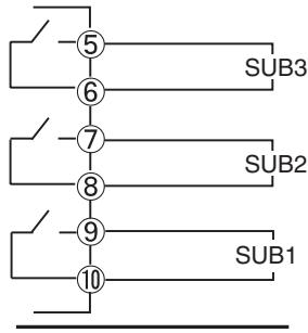
E5AN/EN
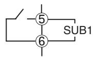
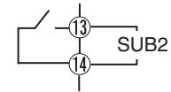
Terminal 14 is on the bottom.
E5GN
ALM1, 2, 3 can be output to auxiliary output 1, 2, 3, or changed with the advanced function setting level.
- The relay specifications are as follows:
| E5CN/AN/EN | SPST-NO, 250 VAC, 3 A |
| E5GN | SPST-NO, 250 VAC, 2 A |
Event Inputs
- The E5□N-□□□B supports event inputs. When event inputs 1/2 are to be used, connect to terminals 11 to 13 or terminals 7 to 9. When event inputs 3/4 are to be used, connect to terminals 23 to 25.
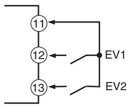
E53-CN□B□N2 in the E5CN-□M□-500 (for E5CN)
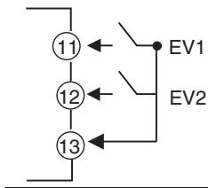
E53-AKB in the E5AN/EN-□M□-500-N (for E5AN/EN)
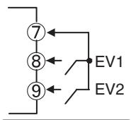
E5GN-□□□B
- Use event inputs under the following conditions:
- The outflow current is approximately 7mA .
| Contact input | ON: 1 kΩ max., OFF: 100 kΩ min. |
| No-contact input | ON: Residual voltage 1.5 V max.; OFF: Leakage current 0.1 mA max. |
Polarities during no-contact input are as follows:
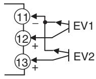
E53-CN□B□N2 in the E5CN-□M□-500 (for E5CN)
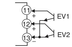
E53-AKB in the E5AN/EN-□M□-500-N (for E5AN/EN)
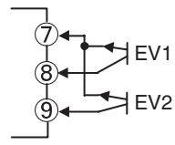
E5GN-□□B
CT Inputs
- When the HB alarm, HS alarm, or heater overcurrent alarm is to be used with the E5CN-□M□-500 with an E53-CN□H/HH□N2 Option Unit, connect a current transformer (CT) across terminals 14 and 15 or terminals 13 and 15 (no polarity).
- When the HB alarm, HS alarm, or heater overcurrent alarm is to be used with the E5AN/EN-□□H□-500-N or E5AN/EN-□□HH□-500-N, connect a current transformer (CT) across terminals 14 and 15 or terminals 15 and 16 (no polarity).
- When using the HB alarm, HS alarm, or heater overcurrent alarm with the E5GN-□□H□, connect the current transformer (CT) across terminals 7 and 8. (no polarity)
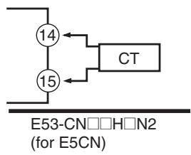
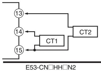
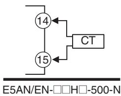
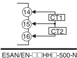
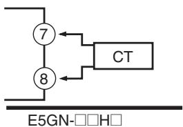
Communications
RS-485
- When communications are to be used with the E5□N-□□□03, connect communications cable across terminals 11 and 12, terminals 21 and 22, or terminals 7 and 8.
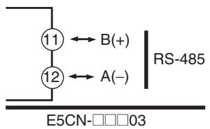
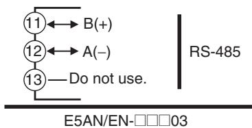
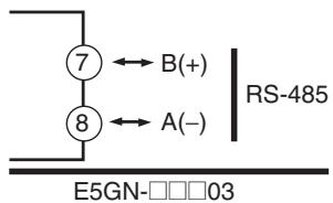
Specify both ends of the transmission path including the host computer as end nodes (that is, connect terminators to both ends). The minimum terminal resistance is 54 Ω.
Communications Unit Connection Diagram
E5CN
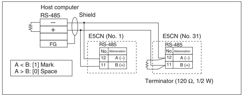
E5AN/EN
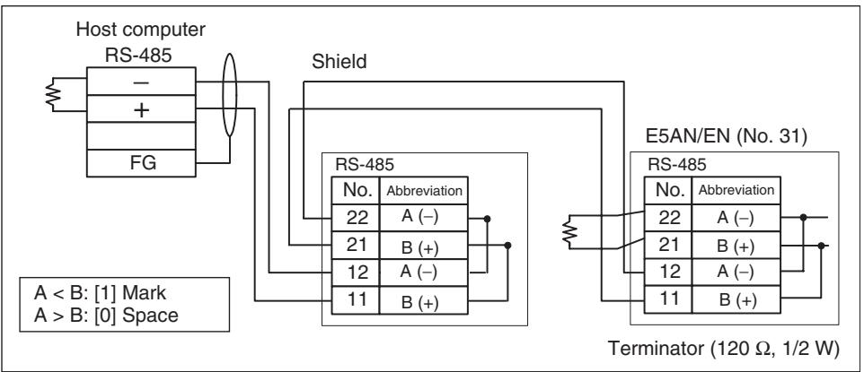
E5GN
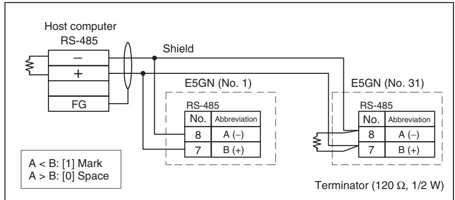
- The RS-485 connection can be either one-to-one or one-to-N. A maximum of 32 Units (including the host computer) can be connected in one-to-N systems. The maximum total cable length is 500m . Use a shielded, AWG24 to AWG14 (cross-sectional area of 0.205 to 2.081mm^2 ) twisted-pair cable for the E5CN, E5EN, or E5AN. Use a shielded, AWG24 to AWG18 (cross-sectional area of 0.205 to 0.823mm^2 ) twisted-pair cable for the E5GN.

RS-232C (E5AN/EN/GN Only)
- When communications are to be used with the E5AN/E5EN/E5GN□□□01□, connect communications cable across terminals 11 to 13 or terminals 7 to 9.
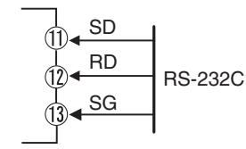
E5AN/EN-□□□01□
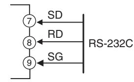
E5GN-□□□01□
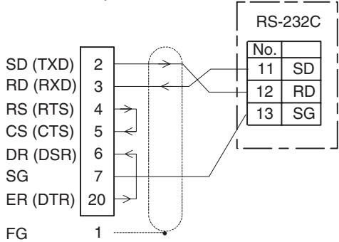
Host computer
RS-232C: 25-pin
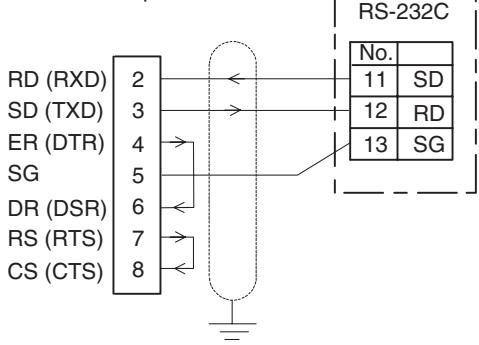
Host computer (DOS/V)
RS-232C: 9-pin
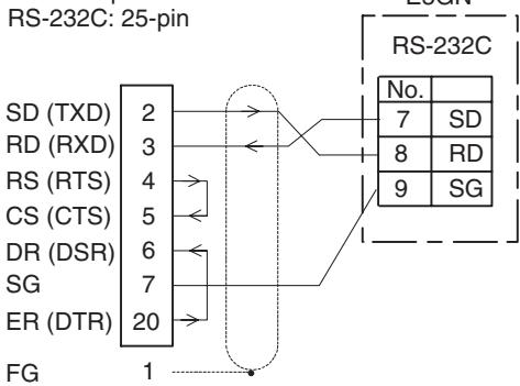
Host computer
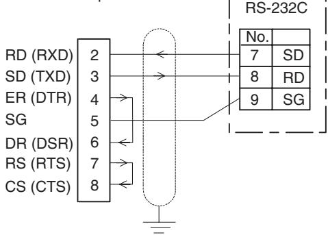
Host computer (DOS/V)
RS-232C: 9-pin
- A 1:1 connection is used. The maximum cable length is 15m . To extend the transmission path, use the OMRON Z3R RS-232C Optical Interface.
- Use a shielded, AWG24 to AWG14 (cross-sectional area of 0.205 to 2.081 ~mm^2 ) twisted-pair cable for the E5CN, E5EN, or E5AN. Use a shielded, AWG24 to AWG18 (cross-sectional area of 0.205 to 0.823 ~mm^2 ) twisted-pair cable for the E5GN.
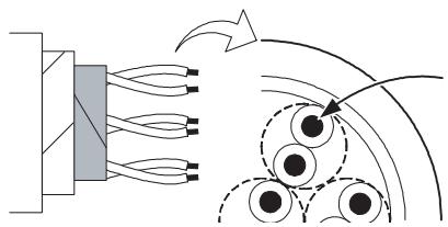
Cross-sectional area of
conductor
AWG24: 0.205 mm²
AWG14:2.081 mm²
External Power Supply for ES1B
-
Connect terminals 11 and 12 when using the E53-CN□□PH□N2 as the external power supply for the ES1B.
-
Connect terminals 14 and 15 when using the E53-CN□□PBN2 as the external power supply for the ES1B.
- Connect terminals 14 and 15 when using the E5AN/EN- P -N as the external power supply for the ES1B.
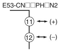
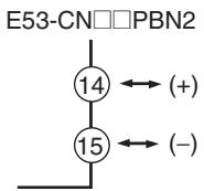
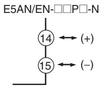
- The following table provides the specifications of the external power supply for ES1B.
| Output voltage | 12 VDC ±10% |
| Output current | 20 mA max. |
Note Contact your OMRON representative for information on using the external power supply for ES1B for other applications.
2-3 Using the Support Software Port
Use the communications port for Support Software to connect the personal computer to the Temperature Controller when using EST2-2C-MV4 CX-Thermo or a version of CX-Thermo higher than 4.00, or other Support Software. The E5GN is supported from CX-Thermo version 4.2. The E58-CIFQ1 USB-Serial Conversion Cable is required to make the connection.
For information concerning the models that can be used with CX-Thermo, contact your OMRON sales representative.
Procedure
Use the following procedure to connect the Temperature Controller to the personal computer using the USB-Serial Conversion Cable. The USB-Serial Conversion Cable is used to communicate with the COM port of the personal computer. To perform communications using USB-Serial Conversion Cable, set the communications port (COM port) number to be used for the software to the COM port assigned to the Cable.
1,2,3... 1. Turn ON the power to the Temperature Controller.
Note If the Cable is connected when the power to the Temperature Controller is OFF, power will be supplied from the personal computer and impose a load on the internal circuits of the Temperature Controller.
- Connect the Cable.
Connect the personal computer's USB port with the Support Software port on the Temperature Controller using the Cable.
- Temperature Controller Connection Method
Personal computer's USB port

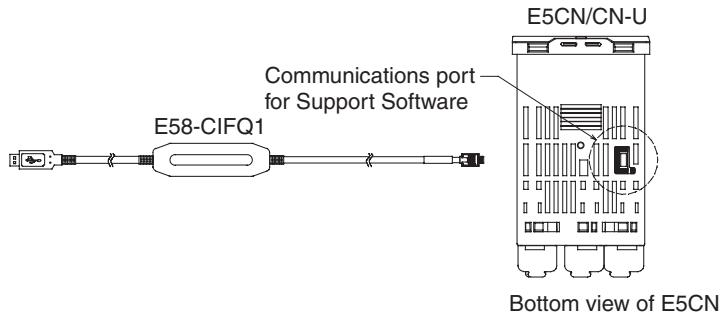
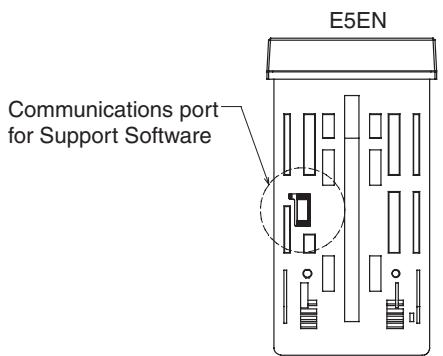
Communications port for Support Software
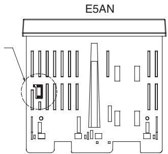
Bottom view of E5AN
Bottom view of E5EN
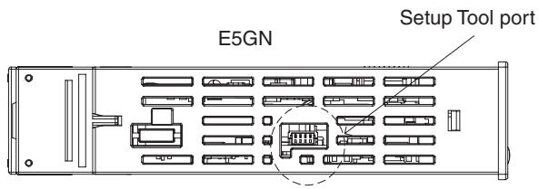
Side View of the E5GN
Note Hold the connector when inserting or disconnecting the Cable.
- Install the driver.
Install the driver to enable the Cable to be used with the personal computer.
- Installation
When the Cable is connected with the personal computer, the OS detects the product as a new device. At this time, install the driver using the installation wizard. For details on installation methods, refer to the user's manual for the E58-CIFQ1 USB-Serial Conversion Cable.
- Setting Setup Tool Communications Conditions
Set the communications port (COM port) number to be used for the CX-Thermo Setup Tool to the COM port number assigned to the USB-Serial Conversion Cable.
Refer to the E58-CIFQ1 USB-Serial Conversion Cable Instruction Manual
and Setup Manual for details on how to check the COM port assigned to the USB-Serial Conversion Cable.
The communications conditions for Setup Tool COM ports are fixed as shown in the table below. Set the communications conditions for the CX-Thermo Setup Tool according to the following table.
| Parameter | Set value |
| Communications Unit No. | 01 |
| Communications baud rate | 38.4 (kbps) |
| Communications data length | 7 (bits) |
| Communications stop bits | 2 (bits) |
| Communications parity | Even |
SECTION 3
Basic Operation
This section describes the basic operation of the E5CN, E5AN, and E5EN Digital Temperature Controllers, including key operations to set parameters and descriptions of display elements based on specific control examples.
3-1 Initial Setting Examples 50
3-2 Setting the Input Type 52
3-2-1 Input Type. 52
3-3 Selecting the Temperature Unit. 54
3-3-1 Temperature Unit 54
3-4 Selecting PID Control or ON/OFF Control 54
3-5 Setting Output Specifications 54
3-5-1 Control Periods. 54
3-5-2 Direct and Reverse Operation. 55
3-5-3 Assigned Output Functions. 56
3-6 Setting the Set Point (SP) 59
3-6-1 Changing the SP 59
3-7 Using ON/OFF Control. 60
3-7-1 ON/OFF Control. 60
3-7-2 Settings 61
3-8 Determining PID Constants (AT, ST, Manual Setup) 62
3-8-1 AT (Auto-tuning) 62
3-8-2 ST(Self-tuning) 64
3-8-3 RT (Robust Tuning) 66
3-8-4 Manual Setup 68
3-9 Alarm Outputs. 69
3-9-1 Alarm Types 69
3-9-2 Alarm Values 71
3-10 Using Heater Burnout, Heater Short, and Heater Overcurrent Alarms. 73
3-10-1 Heater Burnout, Heater Short, and Heater Overcurrent Alarm Operations. 73
3-10-2 Installing Current Transformers (CT). 74
3-10-3 Calculating Detection Current Values 75
3-10-4 Application Examples. 76
3-10-5 Settings: HB Alarm. 80
3-10-6 Settings: Heater Short Alarm 81
3-10-7 Settings: Heater Overcurrent Alarm 82
3-11 Setting the No. 3 Display 84
3-11-1 PV/SP Display Selection 84
3-1 Initial Setting Examples
Initial hardware setup, including the sensor input type, alarm types, control periods, and other settings, is done using parameter displays. The and Keys are used to switch between parameters, and the amount of time that you press the keys determines which parameter you move to.
This section describes two typical examples.
Explanation of Examples
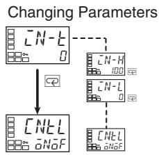
A image means that there are parameters. Continue pressing the key to change parameters until you reach the intended parameter.
Changing Numbers
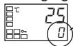
- Numeric data and selections in each screen can be changed by using the and keys.
Example 1
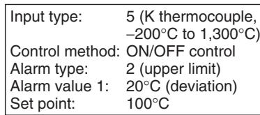
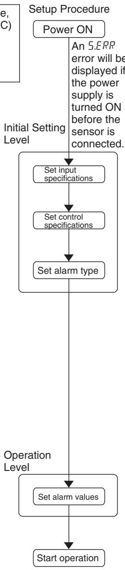
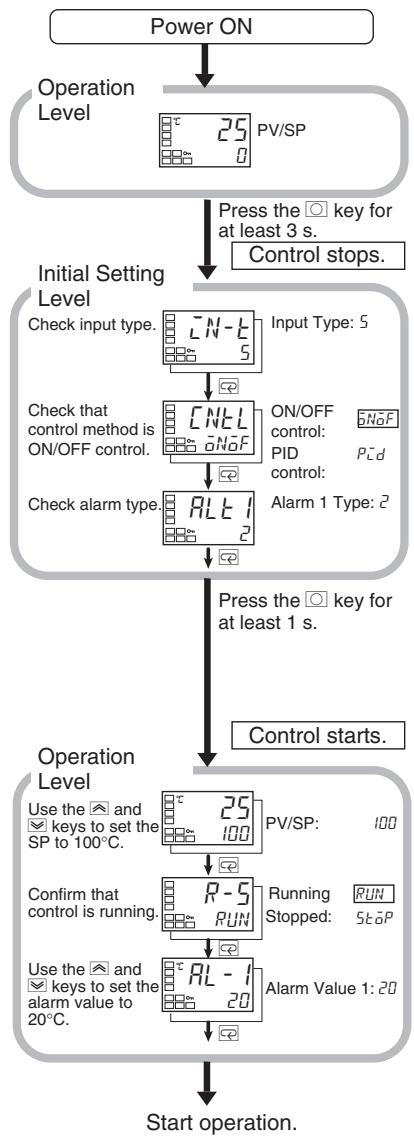
Example 2
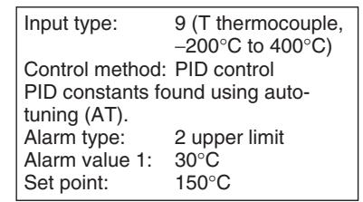

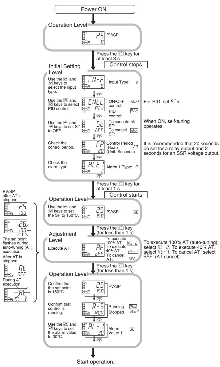
3-2 Setting the Input Type
The Controller supports four input types: platinum resistance thermometer, thermocouple, infrared temperature sensor, and analog inputs. Set the input type that matches the sensor that is used. In the product specifications, there are models with thermocouple/resistance thermometer inputs (universal inputs) and models with analog input. The settings differ depending on the model. Check to make sure which model you are using.
3-2-1 Input Type
Operating Procedure
Operation Level
Initial Setting Level
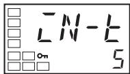
Input Type

The following example shows how to set a K thermocouple for -20.0 to 500.0^ .
- Press the Key for at least three seconds to move from the operation level to the initial setting level.
- Press the Key to enter the set value of the desired sensor. When you use a K thermocouple (-20.0 to 500.0^ ), enter 6 as the set value.
Hint: The key operation is saved two seconds after the change, or by pressing the l or .
List of Input Types
| Input type | Specifications | Set value | Input temperature setting range | |
| Controllers with Ther-mocouple/ResistanceThermometer Multi-input | Platinum resistance thermometer | Pt100 | 0 | -200 to 850 (°C)/-300 to 1,500 (°F) |
| 1 | -199.9 to 500.0 (°C)/-199.9 to 900.0 (°F) | |||
| 2 | 0.0 to 100.0 (°C)/0.0 to 210.0 (°F) | |||
| JPt100 | 3 | -199.9 to 500.0 (°C)/-199.9 to 900.0 (°F) | ||
| 4 | 0.0 to 100.0 (°C)/0.0 to 210.0 (°F) | |||
| Thermocouple | K | 5 | -200 to 1,300 (°C)/-300 to 2,300 (°F) | |
| 6 | -20.0 to 500.0 (°C)/0.0 to 900.0 (°F) | |||
| J | 7 | -100 to 850 (°C)/-100 to 1,500 (°F) | ||
| 8 | -20.0 to 400.0 (°C)/0.0 to 750.0 (°F) | |||
| T | 9 | -200 to 400 (°C)/-300 to 700 (°F) | ||
| 10 | -199.9 to 400.0 (°C)/-199.9 to 700.0 (°F) | |||
| E | 11 | -200 to 600 (°C)/-300 to 1,100 (°F) | ||
| L | 12 | -100 to 850 (°C)/-100 to 1,500 (°F) | ||
| U | 13 | -200 to 400 (°C)/-300 to 700 (°F) | ||
| 14 | -199.9 to 400.0 (°C)/-199.9 to 700.0 (°F) | |||
| N | 15 | -200 to 1,300 (°C)/-300 to 2,300 (°F) | ||
| R | 16 | 0 to 1,700 (°C)/0 to 3,000 (°F) | ||
| S | 17 | 0 to 1,700 (°C)/0 to 3,000 (°F) | ||
| B | 18 | 100 to 1,800 (°C)/300 to 3,200 (°F) | ||
| Infrared temperature sensor ES1B | 10 to 70°C | 19 | 0 to 90 (°C)/0 to 190 (°F) | |
| 60 to 120°C | 20 | 0 to 120 (°C)/0 to 240 (°F) | ||
| 115 to 165°C | 21 | 0 to 165 (°C)/0 to 320 (°F) | ||
| 140 to 260°C | 22 | 0 to 260 (°C)/0 to 500 (°F) | ||
| Analog input | 0 to 50 mV | 23 | Either of the following ranges, by scaling:-1,999 to 9,999-199.9 to 999.9 | |
| Thermocouple | W | 24 | 0 to 2,300 (°C)/0 to 3,200 (°F) | |
| PLII | 25 | 0 to 1,300 (°C)/0 to 2,300 (°F) |
- The default is 5.
- If a platinum resistance thermometer is mistakenly connected while a setting for other than a platinum resistance thermometer is in effect, S.ErrR will be displayed. To clear the S.ErrR display, check the wiring and then turn the power OFF and back ON. Make sure that the setting of the input type parameter agrees with the sensor that is connected.
| Input type | Specifications | Set value | Input temperature setting range | |
| Models with analog input | Current input | 4 to 20 mA | 0 | Either of the following ranges, by scaling: -1,999 to 9,999 -199.9 to 999.9 -19.99 to 99.99 -1.999 to 9.999 |
| 0 to 20 mA | 1 | |||
| Voltage input | 1 to 5 V | 2 | ||
| 0 to 5 V | 3 | |||
| 0 to 10 V | 4 |
- The default is 0.
3-3 Selecting the Temperature Unit
3-3-1 Temperature Unit
Operating Procedure
Operation Level
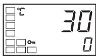
Initial Setting Level
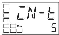
Input Type
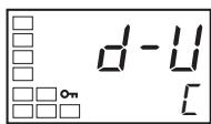
Temperature Unit
- Either ^ C or ^ F can be selected as the temperature unit.
- Set the temperature unit in the Temperature Unit parameter of the initial setting level. The default is (^o C)
The following example shows how to select ^ C as the temperature unit.
-
Press the Key for at least three seconds to move from the operation level to the initial setting level.
-
Select the Temperature Unit parameter by pressing the 或 Key. Press the 或 Key to select either ^ C or ^ F .
E:°C
F:°F
- To return to the operation level, press the Key for at least one second.
3-4 Selecting PID Control or ON/OFF Control
Two control methods are supported: 2-PID control and ON/OFF control. Switching between 2-PID control and ON/OFF control is executed by means of the PID ON/OFF parameter in the initial setting level. When this parameter is set to L^-d , 2-PID control is selected, and when set to ^N , ON/OFF control, is selected. The default is ^N_ .
2-PID Control
PID control is set by AT (auto-tuning), ST (self-tuning), or manual setting.
For PID control, set the PID constants in the Proportional Band (P), Integral Time (I), and Derivative Time (D) parameters.
ON/OFF Control
In ON/OFF control, the control output is turned ON when the process value is lower than the current set point, and the control output is turned OFF when the process value is higher than the current set point (reverse operation).
3-5 Setting Output Specifications
3-5-1 Control Periods
Control Period (Heating)
Control Period (Cooling)
- Set the output periods (control periods). Though a shorter period provides better control performance, it is recommended that the control period be set to 20 seconds or longer for a relay output to preserve the service life of the relay. After the settings have been made in the initial setup, readjust the control period, as required, by means such as trial operation.
- Set the control periods in the Control Period (Heating) and Control Period (Cooling) parameters in the initial setting level. The default is 20 seconds.
- The Control Period (Cooling) parameter is used only for heating/cooling control.
- When control output 1 is used as a current output, Control Period (Heating) cannot be used.
3-5-2 Direct and Reverse Operation
- Direct operation increases the manipulated variable whenever the process value increases. Reverse operation decreases the manipulated variable whenever the process value increases.
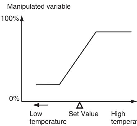
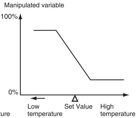
Direct operation
Reverse operation
For example, when the process value (PV) is lower than the set point (SP) in a heating control system, the manipulated variable increases according to the difference between the PV and SP. Accordingly, reverse operation is used in a heating control system. Direct operation is used in a cooling control system, in which the operation is the opposite of a heating control system. The Control Output 1 Assignment is set to (control output (heating)) for either direct or reverse operation.
- Direct/reverse operation is set in the Direct/Reverse Operation parameter in the initial setting level. The default is ^R - (reverse operation).
Operating Procedure
In this example, the input type, temperature unit, direct/reverse operation, and control period (heat) parameters are checked.
Input type = 5 (K thermocouple)
Temperature unit = (^) Direct/reverse operation = R - R (reverse operation)
Control period (heat) = 20 (seconds)
Operation Level
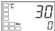
Initial Setting Level
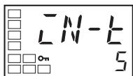
Input Type
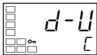
Temperature Unit
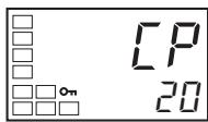
Control Period (Heating)
- Press the Key for at least three seconds to move from the operation level to the initial setting level.
- The input type is displayed. When the input type is being set for the first time, 5 (K thermocouple) is set. To select a different sensor, press the 火 or 火 Key.
- Select the Temperature Unit parameter by pressing the Key. The default is (^ C) . To select F ( ^ F ), press the Key.
- Select the Control Period (Heating) parameter by pressing the 回 Key. The default is 20.
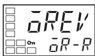
Direct/Reverse Operation
- Select the Direct/Reverse Operation parameter by pressing the Key. The default is R - (reverse operation). To select R - d (direct operation), press the Key.
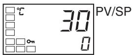
Operation Level
- To return to the operation level, press the Key for at least one second.
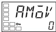
Move to Advanced Function Setting Level
- Select the Move to Advanced Function Setting Level parameter by pressing the 回 Key.
3-5-3 Assigned Output Functions
- Function assignments can be changed by changing the settings for control and auxiliary output assignments.
- The default function assignments for each output are shown below.
| Parameter name | Symbol | Initial status |
| Control Output 1 Assignment | aUb1 | Control output (heating) |
| Control Output 2 Assignment | aUb2 | Not assigned. |
| Auxiliary Output 1 Assignment | 5Ub1 | Alarm 1 |
| Auxiliary Output 2 Assignment | 5Ub2 | Alarm 2 |
| Auxiliary Output 3 Assignment (E5AN/EN only) | 5Ub3 | Alarm 3 |
- Refer to pages 240 to 242 for the functions that can be assigned to the outputs.
- Each output is automatically initialized as shown below by changing the control mode.
Example: E5CN
| Parameter name | Symbol | Without control output 2 | With control output 2 | ||
| Standard | Heating/cooling | Standard | Heating/cooling | ||
| Control Output 1 Assignment | \( \bar{u} \) | Control output (heating) | Control output (heating) | Control output (heating) | Control output (heating) |
| Control Output 2 Assignment | \( \bar{u} \) | Not assigned. (See note 1.) | Not assigned. (See note 1.) | Not assigned. | Control output (cooling) |
| Auxiliary Output 1 Assignment | \( \bar{S} \) | Alarm 1 (See note 2.) | Alarm 1 (See note 2.) | Alarm 1 (See note 2.) | Alarm 1 (See note 2.) |
| Auxiliary Output 2 Assignment | \( \bar{S} \) | Alarm 2 (See note 3.) | Control output (cooling) (See note 3.) | Alarm 2 | Alarm 2 |
Example: E5GN
| Parameter name | Symbol | Standard | Heating/cooling |
| Control Output 1 Assignment | \( \bar{a}U_{\text{ct}} \) | Control output (heating) | Control output (heating) |
| Auxiliary Output 1 Assignment | \( \bar{S}U_{\text{ct}} \) | Alarm 1 (See note 2.) | Control output (cooling) |
| Auxiliary Output 2 Assignment | \( \bar{S}U_{\text{ct}} \) | Alarm 2 | Alarm 2 |
Note
(1) There is no control output 2 and no parameter assignment is displayed for that output.
(2) The Auxiliary Output 1 Assignment parameter becomes the program end output unless the Program Pattern parameter is set to OFF.
(3) For the E5AN/EN, the Auxiliary Output 3 Assignment parameter is set as the control output for cooling. (The Auxiliary Output 2 Assignment parameter is set for alarm 2).
Alarms
It will be specified in this section when an alarm must be assigned, i.e., when an alarm must be set for the Control Output 1 or 2 Assignment parameters, or for the Auxiliary Output 1 to 3 Assignment parameters. For example, if alarm 1 is set for the Control Output 1 Assignment parameter, then alarm 1 has been assigned.
Assigning a work bit to either control output 1 or 2 or to auxiliary output 1 to 3 is also considered to be the same as assigning an alarm. For example, if work bit 1 is set for the Auxiliary Output 1 Assignment parameter, then alarms 1 to 3 have been assigned.
Operating Procedure
This procedure sets the following control and auxiliary output assignments.
Control output 1: Control output (heating); Control output 2: Control output (cooling); Auxiliary output 1: Alarm 1; Auxiliary output 2: Alarm 2
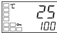
Operation Level
PV/SP
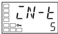
Initial Setting Level
Input Type
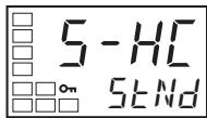
Initial Setting Level
Standard or Heating/Cooling
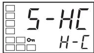
Initial Setting Level
Move to Advanced Function Setting Level
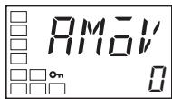
Parameter Initialization
- Press the Key for at least three seconds to move from the operation level to the initial setting level.
-
Select the Standard or Heating/Cooling parameter by pressing the 心 Key.
-
Press the Key to set the parameter to H -
Note The following output assignments do not need to be set because they are set automatically by changing the control mode, but they are shown here as a reference for checking the assignments for each output.
- Select the Move to Advanced Function Setting Level parameter by pressing the . (For details on moving between levels, refer to 4-8 Moving to the Advanced Function Setting Level.)
- Press the Key to enter the password ("-169"), and move from the initial setting level to the advanced function setting level.
Advanced Function Setting Level
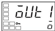
Control Output 1 Assignment
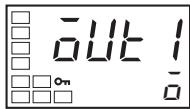
Advanced Function Setting Level
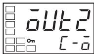
Control Output 2 Assignment
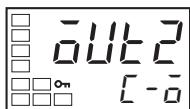
Advanced Function Setting Level
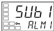
Auxiliary Output 1 Assignment
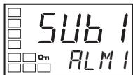
Advanced Function Setting Level
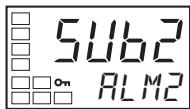
Auxiliary Output 2 Assignment
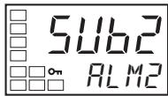
Initial Setting Level
Input Type
Operation Level
PV/SP
Auxiliary Output Opening or Closing in Alarm
- Select the Control Output 1 Assignment parameter by pressing the Key.
- Press the or Key to set . (The default is .)
- Select the Control Output 2 Assignment parameter by pressing the Key.
- Press the or Key to set - (When H - is selected for the Standard or Heating/Cooling parameter, the setting will be - .)
- Select the Auxiliary Output 1 Assignment parameter by pressing the Key.
- Press the 四 or 四 Key to set RLM I. (The default is RLM I.)
- Select the Auxiliary Output 2 Assignment parameter by pressing the Key.
- Press the or Key to set RLM . (The default is RLM .)
- Press the Key for at least one second to move from the advanced function setting level to the initial setting level.
-
Press the Key for at least one second to move from the initial setting level to the operation level.
-
When "close in alarm" is set, the status of the auxiliary output is output unchanged. When "open in alarm" is set, the status of the auxiliary output function is reversed before being output.
Each auxiliary output can be set independently. - These settings are made in the Auxiliary Output 1 to 3 Open in Alarm parameters (advanced function setting level).
-
The default is N - : Close in Alarm.
-
When "open in alarm" is set for the alarm 1 output, the open in alarm status is also applied to heater burnout, HS alarm, heater overcurrent, and input error outputs.
| Auxiliary output functions 1 to 3 | Auxiliary output | Indicators (SUB1 to SUB3) | |
| Close in Alarm | ON | ON | Lit |
| OFF | OFF | Not lit | |
| Open in Alarm | ON | OFF | Lit |
| OFF | ON | Not lit |
- The alarm output will turn OFF (i.e., the relay contacts will open) when power is interrupted and for about two seconds after the power is turned ON regardless of the setting of the Auxiliary Output 1 to 3 Open in Alarm parameter.
3-6 Setting the Set Point (SP)
Operation Level
Operation Level
The operation level is displayed when the power is turned ON. The process value (PV) is at the top of the display, and the set point (SP) is at the bottom.
For Controllers that support a No. 3 display (E5AN/E5EN), the contents set in the PV/SP Display Screen Selection parameter (advanced function setting level) are displayed below the PV and SP.
The MV is displayed as the default. For details, refer to 3-11 Setting the No. 3 Display.
3-6-1 Changing the SP
Operating Procedure
Operation Level
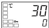
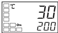
- The set point cannot be changed when the Operation/Adjustment Protect parameter is set to 3. For details, refer to 4-9 Using the Key Protect Level.
- To change the set point, press the 或 in the Process Value/Set Point parameter (in the operation level), and set the desired set value. The new set point is selected two seconds after you have specified the new value.
- Multi-SP is used to switch between two or four set points. For details, refer to 4-5 Using Event Inputs for details.
In this example, the set point is changed from 0^ to 200^ .
- Normally, the Process Value/Set Point parameter is displayed. The set point is 0^ .
- Use the and Keys to set the set point to 200^ .
3-7 Using ON/OFF Control
In ON/OFF control, the control output turns OFF when the temperature being controlled reaches the preset set point. When the manipulated variable turns OFF, the temperature begins to fall and the control turns ON again. This operation is repeated over a certain temperature range. At this time, how much the temperature must fall before control turns ON again is determined by the Hysteresis (Heating) parameter. Also, what direction the manipulated variable must be adjusted in response to an increase or decrease in the process value is determined by the Direct/Reverse Operation parameter.
3-7-1 ON/OFF Control
Hysteresis
- Switching between 2-PID control and ON/OFF control is performed using the PID ON/OFF parameter in the initial setting level. When this parameter is set to L^-d , 2-PID control is selected, and when it is set to N^-F , ON/OFF control is selected. The default is N_^-F .
- With ON/OFF control, hysteresis is used to stabilize operation when switching between ON and OFF. The control output (heating) and control output (cooling) functions are set in the Hysteresis (Heating) and Hysteresis (Cooling) parameters, respectively.
- In standard control (heating or cooling control), the setting of the Hysteresis (Heating) parameter in the adjustment level is used as the hysteresis regardless of whether the control type is heating control or cooling control.
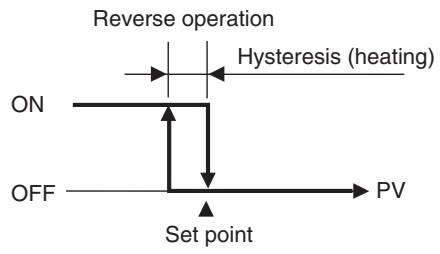
Three-position Control
- In heating/cooling control, a dead band (an area where both control outputs are 0) can be set to either the heating or cooling side. This makes it possible to use 3-position control.
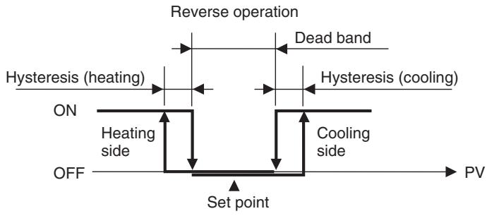
Parameters
| Symbol | Parameter: level | Application |
| S-HE | Standard or Heating/Cooling: Initial setting level | Specifying control method |
| CNEL | PID ON/OFF: Initial setting level | Specifying control method |
| aREV | Direct/Reverse Operation: Initial setting level | Specifying control method |
| c-db | Dead Band: Adjustment level | Heating/cooling control |
| HYS | Hysteresis (Heating): Adjustment level | ON/OFF control |
| CHYS | Hysteresis (Cooling): Adjustment level | ON/OFF control |
3-7-2 Settings
To execute ON/OFF control, set the Set Point, PID ON/OFF, and Hysteresis parameters.
Setting the PID ON/OFF Parameter
Operating Procedure
Operation Level
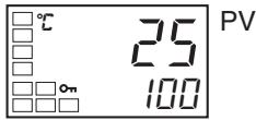
Initial Setting Level
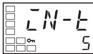
Input Type
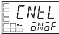
PID ON/OFF
Confirm that the PID ON/OFF parameter is set to N F in the initial setting level.
- Press the Key for at least three seconds to move from the operation level to the initial setting level.
- The Input Type parameter is displayed in the initial setting level.
- Select the PID ON/OFF parameter by pressing the
- Check that the set value is N F (i.e., the default).
- To return to the operation level, press the Key for at least one second. Next, set the set point value.
Setting the SP
Operating Procedure
Operation Level
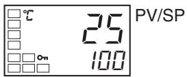
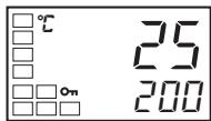
In this example, the set point is set to 200. The set value (i.e., the SP) is shown at the bottom of the display.
- Select the Process Value/Set Point parameter in the operation level.
- Use the and Keys to set the SP. (In this example, it is set to 200.) The new set value can be saved by pressing the Key, or it will go into effect after two seconds have elapsed.
Next, set the hysteresis.
Setting the Hysteresis
Operating Procedure
Operation Level
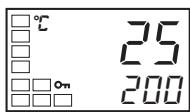
PV
Adjustment Level
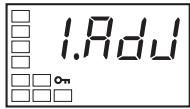
Adjustment Level Display
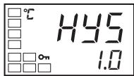
Hysteresis (Heating)
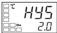
Set the hysteresis to 2.0^
- Press the Key to move from the operation level to the adjustment level.
- The Adjustment Level Display parameter will be displayed in the adjustment level.
- Select the Hysteresis (Heating) parameter by pressing the Key.
- Press the and Keys to set the hysteresis (2.0 in this example). Either press the Key or wait for at least two seconds after setting the hysteresis value to confirm the setting.
- To return to the operation level, press the Key.
3-8 Determining PID Constants (AT, ST, Manual Setup)
3-8-1 AT (Auto-tuning)
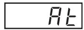
- When AT is executed, the optimum PID constants for the set point at that time are set automatically. A method (called the limit cycle method) for forcibly changing the manipulated variable and finding the characteristics of the control object is employed.
- Either 40% AT or 100% AT can be selected depending on the width of MV variation in the limit cycle. In the AT Execute/Cancel parameter, specify - (100% AT) or - (40% AT). To cancel AT, specify (AT cancel).
- Only 100% AT can be executed for heating and cooling control.
- AT cannot be executed when control has stopped or during ON/OFF control.
- The results of AT are reflected in the Proportional Band (P), Integral Time (I), and Derivative Time (D) parameters in the adjustment level.
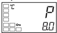
Adjustment Level
Proportional Band
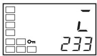
Integral Time
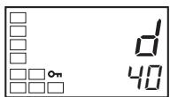
Derivative Time
AT Operations
AT is started when either - (100% AT) or - 1 (40% AT) is specified for the AT Execute/Cancel parameter. During execution, the AT Execute/Cancel parameter on the No. 1 display flashes. When AT ends, the AT Execute/Cancel parameter turns OFF, and the No. 1 display stops flashing.
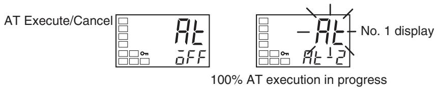
If you move to the operation level during AT execution, the No. 2 display flashes to indicate that AT is being executed.
PV/SP
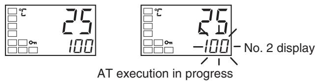
Only the Communications Writing, RUN/STOP, AT Execution/Cancel, and Program Start parameters can be changed during AT execution. Other parameters cannot be changed.
AT Calculated Gain
The AT Calculated Gain parameter sets the gain for when PID values are calculated using AT. When emphasizing response, decrease the set value. When emphasizing stability, increase the set value.
AT Hysteresis
The AT Hysteresis parameter sets the hysteresis when switching ON and OFF for the limit cycle operation during auto-tuning.
Limit Cycle MV Amplitude
The Limit Cycle MV Amplitude parameter sets the MV amplitude for limit cycle operation during auto-tuning.
Note This setting is disabled for 100% AT.
40% AT
The width of MV variation in the limit cycle can be changed in the Limit Cycle MV Amplitude parameter, but the AT execution time may be longer than for 100% AT. The limit cycle timing varies according to whether the deviation (DV) at the start of auto-tuning execution is less than 10% FS.
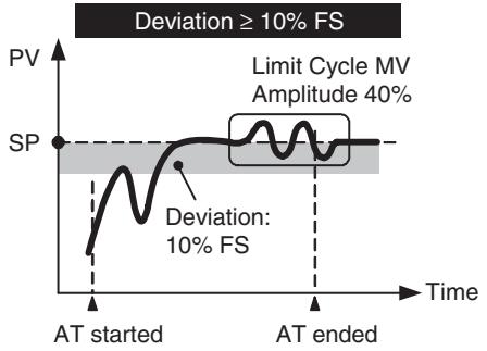
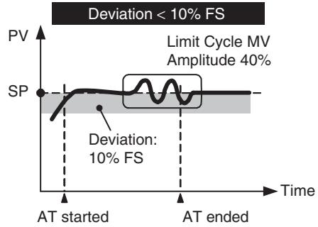
100% AT
Operation will be as shown in the following diagram, regardless of the deviation (DV) at the start of AT execution. To shorten the AT execution time, select 100% AT.
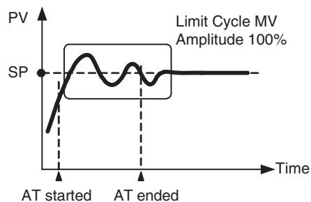
Note The Limit Cycle MV Amplitude parameter is disabled.
Operating Procedure
Adjustment Level
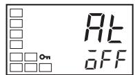
AT Execute/Cancel
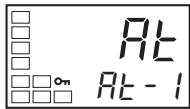
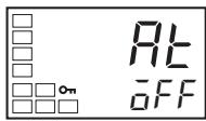
Operation Level
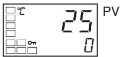
This procedure executes 40% AT.
- Press the l Key to move from the operation level to the adjustment level.
- Press the to select Rt - I . The No. 1 display for AT Execute/Cancel will flash during AT execution.
- F will be displayed when AT ends.
- To return to the operation level, press the Key.
3-8-2 ST (Self-tuning)
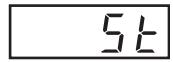
ST (self-tuning) is a function that finds PID constants by using step response tuning (SRT) when Controller operation begins or when the set point is changed.
Once the PID constants have been calculated, ST is not executed when the next control operation is started as long as the set point remains unchanged.
ST (self-tuning) is enabled when the ST parameter is set to ON in the initial setting level.
When the ST function is in operation, be sure to turn the power supply of the load connected to the control output ON simultaneously with or before starting Controller operation.
When executing self-tuning, turn ON power for the load (e.g., heater) at the same time as or before supplying power to the Digital Temperature Controller. If power is turned ON for the Digital Temperature Controller before turning ON power for the load, self-tuning will not be performed properly and optimum control will not be achieved.
Note
PID Constants
When control characteristics are already known, PID constants can be set directly to adjust control. PID constants are set in the Proportional Band (P), Integral Time (I), and Derivative Time (D) parameters in the adjustment level.
Operating Procedure
Initial Setting Level
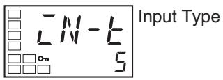
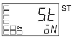
Operation Level
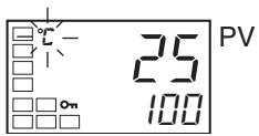
This procedure executes self-tuning (ST).
- Press the Key for at least three seconds to move from the operation level to the initial setting level.
- Select the ST parameter by pressing the Key.
- Press the Key to select ^N . ON is the default.
- To return to the operation level, press the Key for at least one second. The temperature display flashes during self-tuning (ST) execution.
Startup Conditions
Self-tuning by step response tuning (SRT) is started when the following conditions are met after program execution is started and the set point is changed.
| At start of operation | When set point is changed |
| 1. The set point at the start of operation differs from the set point when the previous SRT was executed. (See note 1.)2. The difference between the temperature at the start of operation and the set point is greater both of the following: (Present proportional band × 1.27 + 4°C) and the ST stable range.3. The temperature at the start of operation is lower than the set point during reverse operation, and is larger than the set point during direct operation.4. There is no reset from input errors. | 1. The new set point differs from the set point used when the previous SRT was executed. (See note 1.)2. The set point change width is greater both of the following: (Present proportional band × 1.27 + 4°C) and the ST stable range.3. During reverse operation, the new set point is larger than the set point before the change; and during direct operation, the new set point is smaller than the set point before the change.4. The temperature is stable. (See note 2.) (Equilibrium with the output amount at 0% when the power is turned ON is also all right.) (See note 3.) |
Note
(1) The previous SRT-implemented set point is the set point that was used for calculating the PID constants for the previous SRT.
(2) In this state, the measurement point is within the ST stable range.
(3) In this state, the change width of the PV every 60 seconds is within the ST stable range or less.
In the following instances, PID constants are not changed by self-tuning (ST) for the present set point.
1,2,3...
- When the PID constants have been changed manually with ST set to ON.
- When auto-tuning (AT) has been executed.
ST Stable Range
Operating Procedure
The ST stable range determines the condition under which ST (self-tuning) functions.
Advanced Function Setting Level
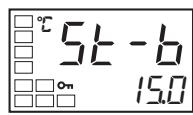
ST Stable Range
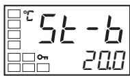
This procedure sets the ST stable range to 20.0^
-
Select the ST Stable Range parameter by pressing the Key in the advanced function setting level.
-
Use the Key to set the parameter to 20.0^ .
3-8-3 RT (Robust Tuning)
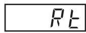
- When AT or ST is executed with RT selected, PID constants are automatically set that make it hard for control performance to degenerate even when the characteristics of the controlled object are changed.
- RT can be set in the advanced function setting level when PID control has been set.
- The RT mode cannot be selected while an analog input is set.
-
Selecting the RT mode in the following cases will help to prevent hunting from occurring.
-
When the set temperature is not constant and is changed in a wide range
- When there are large variations in ambient temperatures due to factors such as seasonal changes or differences between day and night temperatures
- When there are large variations in ambient wind conditions and air flow
- When heater characteristics change depending on the temperature
- When an actuator with disproportional I/O, such as a phase-control-type power regulator, is used
- When a rapidly heating heater is used
- When the control object or sensor has much loss time
- When hunting occurs in normal mode for any reason
- PID constants are initialized to the factory settings by switching to RT mode.
- When the RT mode is selected, the derivative time setting unit becomes the second.
RT Features
- Even when hunting occurs for PID constants when AT or ST is executed in normal mode, it is less likely to occur when AT or ST is executed in RT mode.
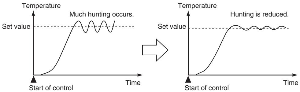
- When the temperature (PV) falls short of the set point for the PID constants when using AT or ST in normal mode, executing AT or ST in RT mode tends to improve performance.
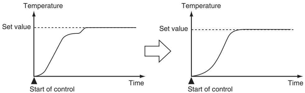
- When the manipulated variable (MV) is saturated, the amount of overshooting may be somewhat higher in comparison to PID control based on AT or ST in normal mode.
Operating Procedure
Operation Level
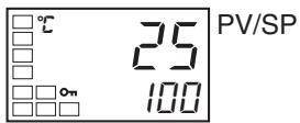
Initial Setting Level
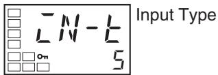
Initial Setting Level
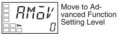
Advanced Function Setting Level
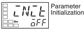
Advanced Function Setting Level
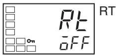
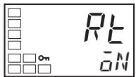
Initial Setting Level
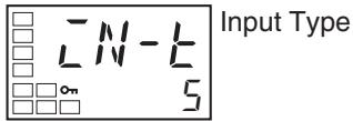
This procedure selects RT mode.
- Press the Key for at least three seconds to move from the operation level to the initial setting level.
- Select the Move to Advanced Function Setting Level parameter by pressing the 回 Key.
- Use the Key to enter "−169" (the password).
It is possible to move to the advanced function setting level by pressing the 回 Key or leaving the setting for at least two seconds. - Press the Key to select RL.
- Press the Key to select N . F F is the default.
- To return to the initial setting level, press the Key for at least one second.
Operation Level
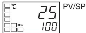
- To return to the operation level, press the Key for at least one second.
3-8-4 Manual Setup
Operating Procedure
Individual PID constants can be manually set in the Proportional Band, Integral Time, and Derivative Time parameters in the adjustment level.
Adjustment Level
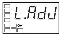
Adjustment Level Display
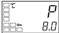
Proportional Band
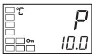
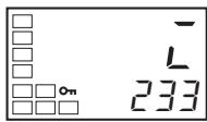
Integral Time
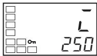
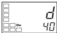
Derivative Time
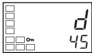
In this example, the Proportional Band parameter is set to 10.0, the Integral Time parameter to 250, and the Derivative Time parameter to 45.
- Press the l Key to move from the operation level to the adjustment level.
- Press the Key to select the proportional band" parameter.
- Use the 和 and 和 Keys to set 10.0.
- Press the Key to select the Integral Time parameter.
- Use the and Keys to set 250.
- Select the Derivative Time operation by pressing the Key.
- Use the 和 and 和 Keys to set 45.
- To return to the operation level, press the Key.
Note Proportional Action
When PID constants I (integral time) and D (derivative time) are set to 0, control is executed according to proportional action. As the default, the center value of the proportional band becomes the set point.
Related parameter: Manual reset value (adjustment level)
When P (Proportional Band) Is Adjusted
| Increased | Set value | The curve rises gradually, and a long stabilization time is created, but over-shooting is prevented. |
| Decreased | Set value | Overshooting and hunting occur, but the set value is quickly reached and the temperature stabilizes. |
When I (Integral Time) Is Adjusted
| Increased | Set value | It takes a long time to reach the set point. It takes time to achieve a stable state, but overshooting, undershooting, and hunting are reduced. |
| Decreased | Set value | Overshooting and undershooting occur. Hunting occurs. The Controller starts up faster. |
When D (Derivative Time) Is Adjusted
| Increased | Set value | Overshooting, undershooting, and stabilization times are reduced, but fine hunting occurs on changes in the curve itself. |
| Decreased | Set value | Overshooting and undershooting increase, and it takes time to return to the set point. |
3-9 Alarm Outputs
- Alarms can be used by the E5CN-□2□□ (2 auxiliary outputs), E5AN/E5EN-□1□□□ (1 auxiliary output), E5AN/E5EN-□3□□□ (3 auxiliary outputs), the E5CN-□1□□□U (1 auxiliary output), the E5CN-□2□□□U (2 auxiliary outputs), E5GN-□1□□□ (1 auxiliary output), and E5GN-□2□□□ (2 auxiliary outputs).
Alarms can also be used by setting the Control Output 1 Assignment or Control Output 2 Assignment parameter to any of the alarms from alarm 1 to 3. The alarm output condition is determined by a combination of the alarm type, alarm value, alarm hysteresis, and the standby sequence. For details, refer to 4-2 Alarm Hysteresis.
- This section describes the Alarm Type, Alarm Value, Upper-limit Alarm and Lower-limit Alarm parameters.
3-9-1 Alarm Types
| Set value | Alarm type | Alarm output operation | Description of function | |
| When alarm value X is positive | When alarm value X is negative | |||
| 0 | Alarm function OFF | Output OFF | No alarm | |
| 1 (See note 1.) | Upper- and lower-limit | ON L;H←OFF SP | See note 2. | Set the deviation in the set point by setting the alarm upper limit (H) and alarm lower limit (L). |
| 2 | Upper-limit | ON X←OFF SP | ON X←OFF SP | Set the upward deviation in the set point by setting the alarm value (X). |
| 3 | Lower-limit | ONOFFSP | ONOFFSP | Set the downward deviation in the set point by setting the alarm value (X). |
| 4 (See note 1.) | Upper- and lower-limit range | ONOFFSP | See note 3. | Set the deviation in the set point by setting the alarm upper limit (H) and alarm lower limit (L). |
| 5 (See note 1.) | Upper- and lower-limit with standby sequence | ONOFFSPSee note 5. | See note 4. | A standby sequence is added to the upper- and lower-limit alarm (1). (See note 6.) |
| 6 | Upper-limit with standby sequence | ONOFFSP | ONOFFSP | A standby sequence is added to the upper-limit alarm (2). (See note 6.) |
| 7 | Lower-limit with standby sequence | ONOFFSP | ONOFFSP | A standby sequence is added to the lower-limit alarm (3). (See note 6.) |
| 8 | Absolute-value upper-limit | ONOFF0 | ONOFF0 | The alarm will turn ON if the process value is larger than the alarm value (X) regardless of the set point. |
| 9 | Absolute-value lower-limit | ONOFF0 | ONOFF0 | The alarm will turn ON if the process value is smaller than the alarm value (X) regardless of the set point. |
| 10 | Absolute-value upper-limit with standby sequence | ONOFF0 | ONOFF0 | A standby sequence is added to the absolute-value upper-limit alarm (8). (See note 6.) |
| 11 | Absolute-value lower-limit with standby sequence | ONOFF0 | ONOFF0 | A standby sequence is added to the absolute-value lower-limit alarm (9). (See note 6.) |
| 12 | LBA (alarm 1 type only) | --- | Refer to page 118. (See note 7.) | |
| 13 | PV change rate alarm | --- | Refer to page 72. (See note 8.) | |
Note
(1) With set values 1, 4, and 5, the upper- and lower-limit values can be set independently for each alarm type, and are expressed as “L” and “H.”
(2) Set value: 1 (Upper- and lower-limit alarm)
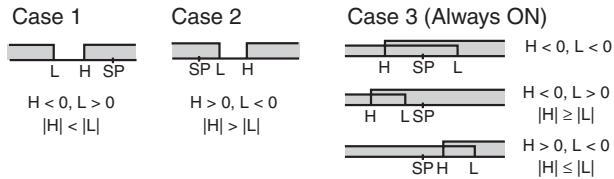
(3) Set value: 4 (Lower limit range)
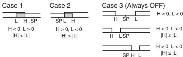
(4) Set value: 5 (Upper- and lower-limit with standby sequence)
- For the lower-limit alarms in cases 1 and 2 above, the alarm is always OFF if upper- and lower-limit hysteresis overlaps.
- In case 3, the alarm is always OFF.
(5) Set value: 5 (Upper- and lower-limit with standby sequence)
- The alarm is always OFF if upper- and lower-limit hysteresis overlaps.
(6) Refer to 4-2-1 Standby Sequence for information on the operation of the standby sequence.
(7) Refer to 4-12-1 Loop Burnout Alarm (LBA).
(8) Refer to PV Change Rate Alarm on page 72.
- Set the alarm type independently for each alarm in the Alarm 1 to 3 Type parameters in the initial setting level. The default is 2 (Upper-limit alarm).
3-9-2 Alarm Values
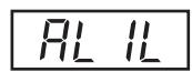
Alarm Lower Limit Value
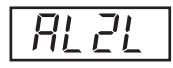
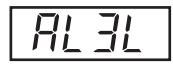
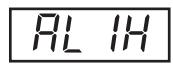
Alarm Upper Limit Value
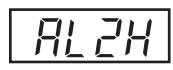
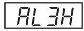
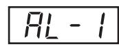
Alarm Value
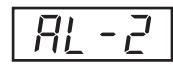
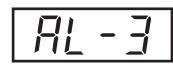
Operating Procedure
- Alarm values are indicated by "X" in the table on the previous page. When the upper and lower limits are set independently, "H" is displayed for upper limit values, and "L" is displayed for lower limit values.
- To set the alarm value upper and lower limits for deviation, set the upper and lower limits in each of the Alarm 1 to 3 Upper Limit, and Alarm 1 to 3 Lower Limit parameters in the operation level.
This procedure sets alarm 1 as an upper-limit alarm. The related parameters and settings are shown below. The alarm is output when the set point exceeds 10^ . (In this example, the temperature unit is ^ C .)
Alarm 1 type = 2 (Upper-limit alarm)
Alarm value 1 = 10
Initial Setting Level
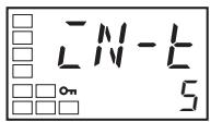
Input Type
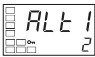
Alarm 1 Type
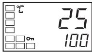
PV/SP
- Press the Key for at least three seconds to move from the operation level to the initial setting level.
- Select the Alarm 1 Type parameter by pressing the Key. Confirm that the set value is 2. The default value is 2 (Upper-limit alarm).
- To return to the operation level, press the Key for at least one second.
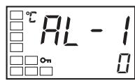
Alarm Value 1
- Select the Alarm Value 1 parameter by pressing the 一 Key.
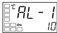
- Use the Key to set the parameter to 10.
PV Change Rate Alarm
The change width can be found for PV input values in any set period. Differences with previous values in each set period are calculated, and an alarm is output if the result exceeds the alarm value. The PV rate of change calculation period can be set in units of 250 ms.
If a positive value is set for the alarm value, the PV will operate as a change rate alarm in the rising direction. If a negative value is set, the PV will operate as a change rate alarm in the falling direction.
Precaution
If a shorter PV rate of change calculation period is set, outputs set for the PV change rate alarm function may repeatedly turn ON and OFF for a short period of time. It is therefore recommended that the PV change rate alarm be used with the alarm latch turned ON.
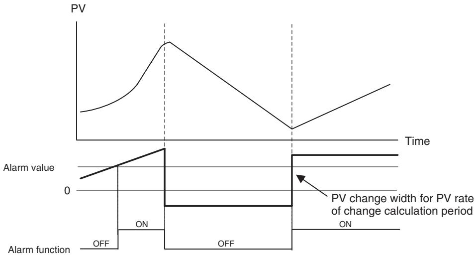
| Parameter name | Setting range | Unit | Default |
| PV Rate of Change Calcu-lation Period | 1 to 999 | Sampling cycle | 4 (1 s) |
3-10 Using Heater Burnout, Heater Short, and Heater Overcurrent Alarms
3-10-1 Heater Burnout, Heater Short, and Heater Overcurrent Alarm Operations
- Heater burnout detection and heater overcurrent detection are executed by measuring heater current while the control output (heating) is ON, and heater short detection is executed by measuring heater current while it is OFF. For details, refer to the following table. (Heater burnout detection, heater short detection, and heater overcurrent detection cannot be used with the control output for cooling.)
| Control output (heating) status | Power to heater | HB alarm output | HS alarm output | Heater overcurrent alarm output | |
| Control output (heating) | Operation indicator | ||||
| ON | Lit | Yes (Normal) (See note 1.) | OFF | --- | --- |
| No (Heater burnout) | ON | --- | --- | ||
| OFF | Not lit | Yes (HS alarm) | --- | ON | --- |
| No (Normal) (See note 2.) | --- | OFF | --- | ||
| ON | Lit | Normal | --- | --- | OFF |
| Heater overcurrent status (See note 3.) | --- | --- | ON | ||
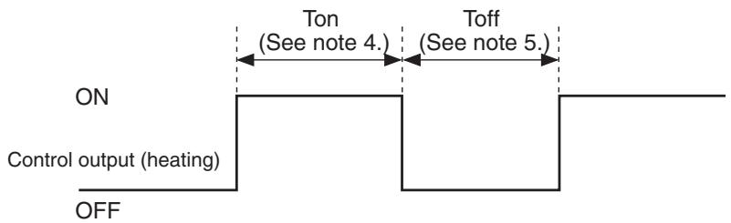
Note
(1) In the above diagram, power is considered to be ON (normal) if the heater current is greater than the heater burnout detection current during the Ton interval. If the heater is burned out, the measured current decreases and falls below the heater burnout detection value. The output is then activated as the heater burnout alarm.
(2) In the above diagram, power is considered to be OFF (normal) if the leakage current is less than the HS alarm current during the Toff interval. If the SSR output is short-circuited, the measured current increases beyond the HS alarm value. The output is then activated as the HS alarm.
(3) In the above diagram, it is regarded as normal when the heater current is less than the heater overcurrent detection current during the Ton period. Current is increased when excessive current flows to the heater, causing the heater overcurrent detection value to be exceeded and an OC (heater overcurrent) alarm to be output.
(4) Heater burnout and heater overcurrent are not detected if the control output (heating) ON time (Ton) is 100 ms or less.
(5) HS alarms are not detected if the control output (heating) OFF time (Toff) is 100 ms or less.
- For Controllers with heater burnout, HS, and heater overcurrent alarms, an OR output is established between the ALM 1 function and the alarms. If the ALM1 function is to be used for the heater burnout, HS, and heater overcurrent alarms only, set 0 as the alarm 1 type (i.e., do not use ALM1).
- Turn the heater power ON simultaneously or before turning ON the E5□N power. If the heater power is turned ON after turning ON the E5AN power, the HB alarm will be activated.
- Control is continued even when the heater burnout, HS, or heater overcurrent alarm is active.
- The rated current value may sometimes differ slightly from the actual current flowing to the heater.
Use the Heater Current 1 Value Monitor, Heater Current 2 Value Monitor, Leakage Current 1 Monitor, and Leakage Current 2 Monitor parameters to check the actual current being used.
- If there is little difference between the current in normal and abnormal states, detection may become unstable. To stabilize detection, set a current value difference of at least 1.0A for heaters of less than 10.0A , and at least 2.5A for heaters of 10.0A or more. If the heater current is too low, loop the load line several times through a CT, as shown in the diagram below. Looping it through once will double the detection current.
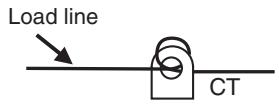
3-10-2 Installing Current Transformers (CT)
- This function can be used with E5□N models that have the HB alarm, HS alarm, and OC alarm.
For the E5CN, connect the CT in advance to terminals 14 and 15 (CT1), or 13 and 15 (CT2). For the E5AN/E5EN, connect the CT in advance to terminals 14 and 15 (CT1) or 15 and 16 (CT2). For the E5GN, connect the CT in advance to terminals 7 and 8 (CT1). Then pass the heater power line through the CT's hole. For specifications, models and dimensions of current transformers that can be used with this Controller, refer to Appendix Current Transformer (CT) on page 279.
Single-phase Heaters
For single-phase heaters, install the CT in the position shown in the following diagram.
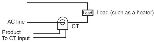
Three-phase Heaters (E5AN-□□HH□-N, E5EN-□□HH□-N, and E53-CN□□HHN2 (for E5CN) 3-phase Heater Detection Models)
When a 3-phase power supply is used, regardless of the types of connecting lines, two current transformers (CTs) are required to detect heater burnout, HS, and OC.
1,2,3... 1. Delta connecting lines: Refer to the following diagram for CT installation positions.
Note Heater voltage fluctuations are not considered here, so be take that into account when setting the detection current.
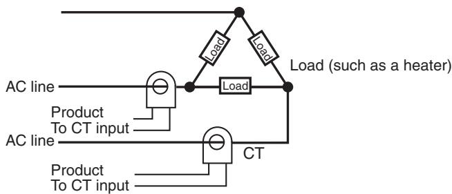
- Star connecting lines: Refer to the following diagram for CT installation positions.
Note Heater voltage fluctuations are not considered here, so be take that into account when setting the detection current.
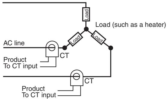
- V connecting lines: Refer to the following diagram for CT installation positions.
Note Heater voltage fluctuations are not considered here, so be take that into account when setting the detection current.
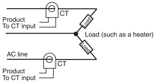
3-10-3 Calculating Detection Current Values
- Calculate the set value using the following equation:
$$ \text {H e a t e r B u r n o u t D e t e c t i o n 1 / 2 s e t v a l u e} = \frac {\text {N o r m a l c u r r e n t v a l u e} + \text {B u r n o u t c u r r e n t v a l u e}}{2} $$
$$ H S A l a r m 1 / 2 s e t v a l u e = \frac {\text {L e a k a g e c u r r e n t v a l u e (o u t p u t O F F) + H S c u r r e n t v a l u e}}{2} $$
$$ \text {H e a t e r o v e r c u r r e n t 1 / 2 s e t v a l u e} = \frac {\text {N o r m a l c u r r e n t v a l u e} + \text {O v e r c u r r e n t v a l u e}}{2} $$
-
To set the current for heater burnout when two or more heaters are connected through the CT, use the value from when the heater with the smallest current burns out. If all of the heaters have the same current, use the value from when any one of them burns out.
-
Make sure that the following conditions are satisfied:
Heater with a current of less than 10.0 A:
(Current value at normal operation) - (Current value at heater burnout) ≥ 1 A
When the difference is less than 1 A, detection is unstable.
Heater with a current of 10.0 A or more:
(Current value at normal operation) - (Current value at heater burnout) ≥ 2.5 A
When the difference is less than 2.5A , detection is unstable.
- The setting range is 0.1 to 49.9 A. Heater burnout, HS, and heater overcurrent are not detected when the set value is 0.0 or 50.0. When the set value is 0.0, the heater burnout alarm is always OFF, the HS alarm is always ON, and the heater overcurrent alarm is always ON. When the set value is 50.0, the heater burnout alarm is always ON, the HS alarm is always OFF, and the heater overcurrent alarm is always OFF.
- Set the total current value for normal heater operation to 50 A or less. When a current value of 55.0 A is exceeded, FFFF is displayed in the Heater Current 1 (or 2) Value Monitor and Leakage Current 1 (or 2) Monitor parameters.
3-10-4 Application Examples
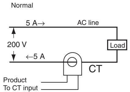
Single-phase Heaters
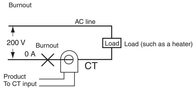
Example: Using a 200-VAC, 1-kW Heater
The heater power supply provides 5 A when the current is normal, and 0 A when there is a burnout, so the heater burnout detection current is calculated as follows:
$$ \begin{array}{l} \text {H e a t e r b u r n o u t d e t e c t i o n c u r r e n t} = \frac {\text {(N o r m a l c u r r e n t)} + \text {(H e a t e r b u r n o u t c u r r e n t)}}{2} \ = \frac {5 + 0}{2} = 2. 5 [ A ] \ \end{array} $$
Example: Using Three 200-VAC, 1-kW Heaters
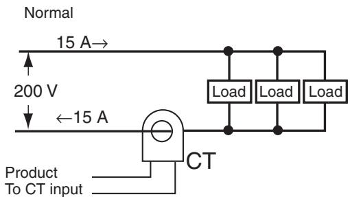
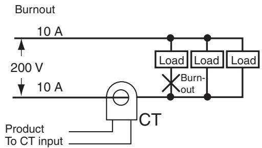
The heater power supply provides 15 A when the current is normal, and 10 A when there is a burnout, so the heater burnout detection current is calculated as follows:
Heater burnout detection current = (Normal current) + (Heater burnout current)2
$$ = \frac {1 5 + 1 0}{2} = 1 2. 5 [ A ] $$
Three-phase Heaters
Delta Connecting Lines
Example: Using Three 200-VAC, 2-kW Heaters
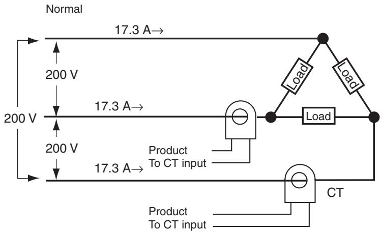
The current when each phase is normal is 17.3 A ( ≈ 3 × 10 A).
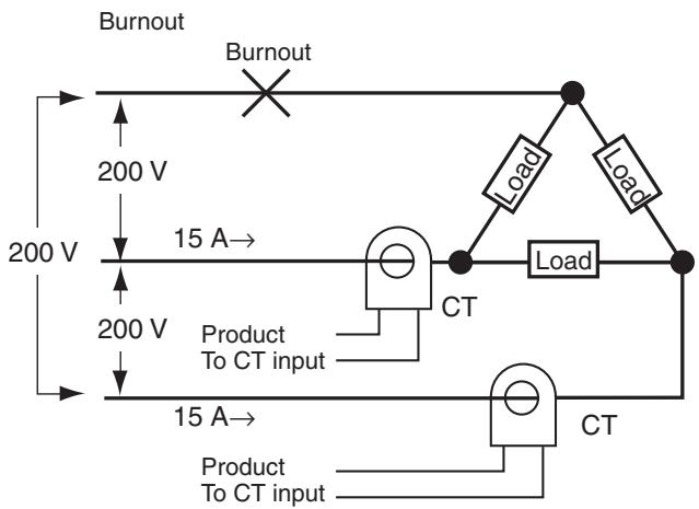
Current when there is a burnout = 10A× 3×
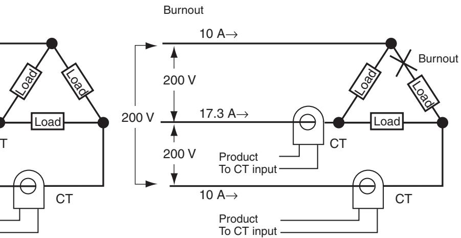
Current when there is a burnout = 10A× 3×
The heater burnout current when there is a burnout at the load line is as follows:
(1 / 3) = 10A
(Heater burnout detection current) = (17.3 + 15) / 2 ≈ 16.1 [A]
The heater burnout current when there is a burnout at the load is as follows:
(Heater burnout detection current) = (17.3 + 10) / 2 ≈ 13.65 [A]
To enable detection in either case, use 16.1 A as the heater burnout detection current.
Star Connecting Lines
Example: Using Three 200-VAC, 2-kW Heaters
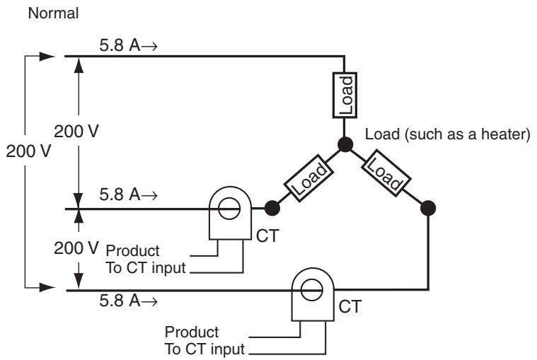
The current when each phase is normal is 5.8A (≈ 10A × (1 / 3))
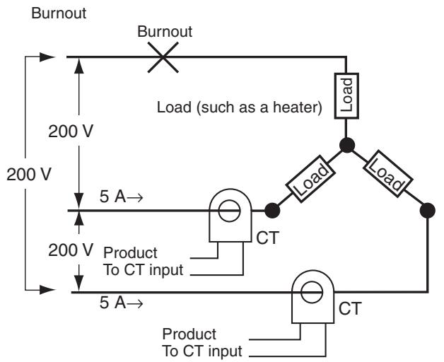
Current when there is a burnout = 10A× (1 / 3)
× ( 3/2) = 5 A

Current when there is a burnout = 10A× (1 / 3)
× (3 / 2) = 5A
The heater burnout detection current for this connecting line is 5.4 A ( = (5.8 + 5) / 2 ).
V Connecting Lines
Example: Using Two 200-VAC, 2-kW Heaters

Normal
Burnout
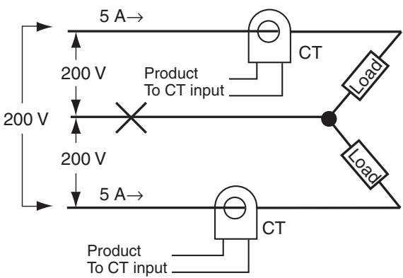
Current when there is a burnout = 10A× (1 / 2) = 5A
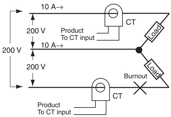
Current when there is a burnout = 0 A
The heater burnout current when there is a burnout at the common is as follows:
Heater burnout detection current = (10 + 5) / 2 ≈ 7.5 [A]
The heater burnout current when there is a burnout at the load is as follows: Heater burnout detection current = (10 + 0) / 2 ≈ 5 [A]
To enable detection in either case, use 7.5 A as the heater burnout detection current.
3-10-5 Settings: HB Alarm
To activate the heater burnout alarm, set the HB ON/OFF parameter to ON in the advanced function setting level and set the Heater Burnout Detection 1 and Heater Burnout Detection 2 parameters in the adjustment level.
Operating Procedure
This procedure sets the Heater Burnout Detection 1 parameter to 2.5.
■ Moving to the Advanced Function Setting Level
The Heater Burnout Detection parameter setting is already ON by default, so set the Heater Burnout Detection 1 parameter.
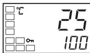
Operation Level
PV/SP
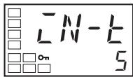
Initial Setting Level
Input Type
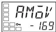
Initial Setting Level
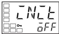
Advanced Function Setting Level
Moves to Advanced Function Setting Level
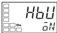
Heater Burnout Detection
- Move to the advanced function setting level.
Press the Key for at least three seconds to move from the operation level to the initial setting level.
- Select Move to Advanced Function Setting Level by pressing the Key.
(For details on moving between levels, refer to 4-8 Moving to the Ad
vanced Function Setting Level.)
- Press the × Key to enter the password (-169), and move from the initial
setting level to the advanced function setting level.
The top parameter in the advanced function setting level is displayed.
- Select the Heater Burnout Detection parameter by pressing the 一 Key.
Check that this parameter is set to ON (the default).
Next, set the Heater Burnout Detection 1 parameter.
Setting Heater Burnout Detection
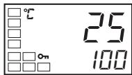
Operation Level
PV/SP
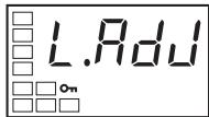
Adjustment Level
Adjustment Level Display

Heater Current 1 Value Monitor
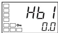
Heater Burnout Detection 1
- Press the Key for at least one second to move from the advanced
function setting level to the initial setting level. Press the l key again for
at least one second to move to the operation level.
- Press the Key for less than one second to move from the operation
level to the adjustment level.
- Select the Heater Current 1 Value Monitor parameter by pressing the
Key. Check the current value. Next, set the Heater Burnout Detection 1
parameter.
- Select the Heater Burnout Detection 1 parameter by pressing the Key.
Refer to Calculating Detection Current Values on page 75 on when mak
ing the settings.
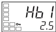
- For this example, set 2.5. To return to the operation level, press the Key for less than one second.
3-10-6 Settings: Heater Short Alarm
To activate the HS alarm, set the HS Alarm Use parameter to ON in the advanced function setting level and set the HS Alarm 1 and HS Alarm 2 parameters in the adjustment level.
Operating Procedure
This procedure sets the HS Alarm 1 parameter to 2.5.
■ Moving to the Advanced Function Setting Level
The HS Alarm Use parameter setting is already ON by default, so set the HS Alarm 1 parameter.
Operation Level
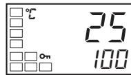
PV/SP
Initial Setting Level
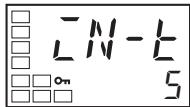
Input Type
Initial Setting Level

Advanced Function Setting Level
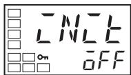
Move to the Advanced Function Setting Level
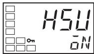
HS Alarm Use
- Move to the advanced function setting level.
Press the Key for at least three seconds to move from the operation level to the initial setting level. - Select Move to Advanced Function Setting Level by pressing the l Key. (For details on moving between levels, refer to 4-8 Moving to the Advanced Function Setting Level.)
- Press the to enter the password (-169), and move from the initial setting level to the advanced function setting level.
The top parameter in the advanced function setting level is displayed.
- Select the HS Alarm Use parameter by pressing the Key. Check that this parameter is set to ON (the default). Next, set the HS Alarm 1 parameter.
HS Alarm Settings
Operation Level
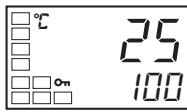
PV/SP
- Press the Key for at least one second to move from the advanced function setting level to the initial setting level. Press the key again for at least one second to move to the operation level.
Adjustment Level
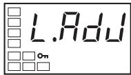
Adjustment Level Display
- Press the Key for less than one second to move from the operation level to the adjustment level.
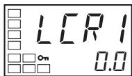
Leakage Current 1 Monitor
- Select the Leakage Current 1 Monitor parameter by pressing the Key. Check the current value. Next, set the HS Alarm 1 parameter.
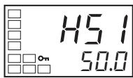
HS Alarm 1
- Select the HS Alarm 1 parameter by pressing the . Refer to Calculating Detection Current Values on page 75 when setting the values.

- For this example, set 2.5. To return to the operation level, press the Key for less than one second.
3-10-7 Settings: Heater Overcurrent Alarm
To activate heater overcurrent alarm, set the Heater Overcurrent Use parameter to ON in the advanced function setting level and set the Heater Overcurrent Detection 1 and Heater Overcurrent Detection 2 parameters in the adjustment level.
Operating Procedure
This procedure sets the Heater Overcurrent Detection 1 parameter to 20.0.
■ Moving to the Advanced Function Setting Level
The default setting for the Heater Overcurrent Use parameter is ON, so set the Heater Overcurrent Detection 1 parameter.
Operation Level
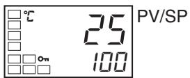
PV/SP
- Move to the advanced function setting level.
Press the Key for at least three seconds to move from the operation level to the initial setting level.
Initial Setting Level
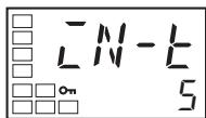
Input Type
- Press the l Key to select the Move to Advanced Function Setting Level parameter. (For details on moving between levels, refer to 4-8 Moving to the Advanced Function Setting Level.)
Initial Setting Level
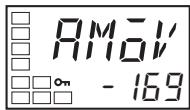
- Press the to enter the password (-169), and move from the initial setting level to the advanced function setting level.
Advanced Function Setting Level
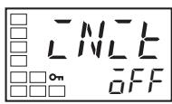
Move to the Advanced Function Setting Level
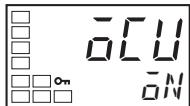
Heater Overcurrent Use
The top parameter in the advanced function setting level is displayed.
- Press the l Key to select the Heater Overcurrent Use parameter. Check that this parameter is set to ON (the default), and then set the Heater Overcurrent Detection 1 parameter.
Setting Heater Overcurrent Detection
Operation Level
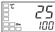
PV/SP
- Press the Key for at least one second to move from the advanced function setting level to the initial setting level. Press the key again for at least one second to move to the operation level.
- Press the Key for less than one second to move from the operation level to the adjustment level.
Adjustment Level
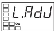
Adjustment Level Display
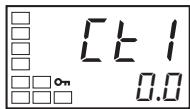
Heater Current 1 Value Monitor
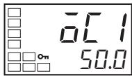
Heater Overcurrent Detection 1
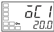
- Press the Key to select the Heater Current 1 Value Monitor parameter. Check the current value, and then set the Heater Overcurrent Detection parameter.
- Press the Key to select the Heater Overcurrent Detection 1 parameter. Refer to Calculating Detection Current Values on page 75 when setting the values.
- For this example, set 20.0. To return to the operation level, press the Key for less than one second.
3-11 Setting the No. 3 Display
This section describes how to set the No. 3 Display (E5AN/EN). The Multi-SP, MV, or soak time remain can be displayed on the No. 3 display.
3-11-1 PV/SP Display Selection
The following table shows the set values and display contents for the PV/SP Display selection.
| Set value | Display contents |
| 0 | Only PV/SP is displayed (with no No. 3 display.) |
| 1 | PV/SP/Multi-SP and PV/SP/MV are displayed in order. (See note.) |
| 2 | PV/SP/MV and PV/SP/Multi-SP are displayed in order. (See note.) |
| 3 | Only PV/SP/Multi-SP is displayed. |
| 4 | Only PV/SP/MV is displayed. (See note.) |
| 5 | PV/SP/Multi-SP and PV/SP/Soak time remain are displayed in order. |
| 6 | PV/SP/MV and PV/SP/Soak time remain are displayed in order. (See note.) |
| 7 | Only PV/SP/Soak time remain is displayed. |
- A 2-level display is set when shipped from the factory. (set value: 0)
A 3-level display is activated if parameters are initialized. (set value: 4)
Note
For details on setting the MV for heating and cooling control, refer to MV Display for Heating and Cooling Control below.
When 1, 2, 5, or 6 is selected, press the Key to display the next value set for the PV/SP display (display 2).
Example: When the PV/SP Display Screen Parameter Is Set to 2
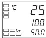
Operation Level PV/SP (Display 1)
PV/SP/MV

Press the
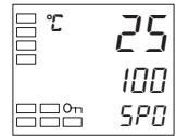
PV/SP (Display 2)
PV/SP/Multi-SP
MV Display for Heating and Cooling Control
Select either the manipulated variable (heating) or manipulated variable (cooling) as the MV to be displayed for PV/SP/MV during heating and cooling control. The MV Display Selection parameter is displayed only when heating/cooling control is being performed and PV/SP/MV is selected in the PV/SP Display Screen parameter or a Monitor/Setting Item Display parameter.
| Parameter name | Set value | Symbol | Display contents |
| MV Display Selection | O | \(\bar{a}\) | Manipulated variable (heating) |
| C-O | \(\bar{c}-\bar{a}\) | Manipulated variable (cooling) |
Operating Procedure
This procedure displays PV/SP/MV and PV/SP/Multi-SP on the Process Value/Set Point display. The PV/SP Display Screen Selection parameter is set to 2.
Operation Level
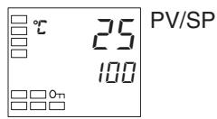
Initial Setting Level
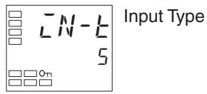
Initial Setting Level
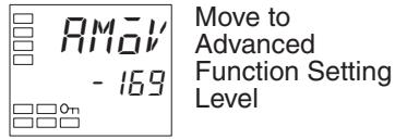
Advanced Function Setting Level
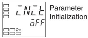
Advanced Function Setting Level
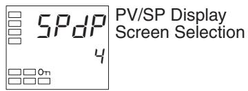
Initial Setting Level
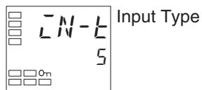
Operation Level
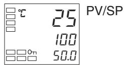
Operation Level
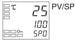
- Press the Key for at least three seconds to move from the operation level to the initial setting level.
- Press the Key to select the Move to Advanced Function Setting Level parameter.
- Use the Key to enter the password ("-169"). It is possible to move to the advanced function setting level by either pressing the Key or waiting two seconds without pressing any key.
- Press the Key to select the PV/SP Display Screen Selection parameter.
- Use the and Keys to set .
- Press the Key for at least one second to move from the advanced function setting level to the initial setting level.
- Press the Key for at least one second to move from the initial setting level to the operation level. The MV will be displayed on the No. 3 display.
- Press the Key to confirm that the Multi-SP is displayed on the No. 3 display.
SECTION 4
Applications Operations
This section describes scaling, the SP ramp function, and other special functions that can be used to make the most of the functionality of the E5CN, E5AN, and E5EN Digital Temperature Controllers.
4-1 Shifting Input Values. 89
4-1-1 Shifting Inputs 89
4-1-2 How to Calculate Input Shift Values for a 2-point Shift. 90
4-2 Alarm Hysteresis. 93
4-2-1 Standby Sequence. 93
4-2-2 Alarm Latch 94
4-3 Setting Scaling Upper and Lower Limits for Analog Inputs 94
4-3-1 Analog Input. 94
4-4 Executing Heating/Cooling Control 95
4-4-1 Heating/Cooling Control 95
4-4-2 Settings 98
4-5 Using Event Inputs 99
4-5-1 Event Input Settings 99
4-5-2 How to Use the Multi-SP Function. 101
4-5-3 Settings 102
4-5-4 Operation Commands Other than Multi-SP 102
4-6 Setting the SP Upper and Lower Limit Values 104
4-6-1 Set Point Limiter. 104
4-6-2 Setting. 105
4-7 Using the SP Ramp Function to Limit the SP Change Rate. 106
4-7-1 SP Ramp. 106
4-8 Moving to the Advanced Function Setting Level 108
4-9 Using the Key Protect Level 110
4-9-1 Protection 110
4-9-2 Entering the Password to Move to the Protect Level 111
4-10 PV Change Color 113
4-10-1 PV Color Change Function. 113
4-10-2 Setting. 114
4-11 Alarm Delays 116
4-11-1 Alarm Delays 116
4-12 Loop Burnout Alarm. 118
4-12-1 Loop Burnout Alarm (LBA). 118
4-13 Performing Manual Control 122
4-13-1 Manual Operation. 122
4-14 Using the Transfer Output. 126
4-14-1 Transfer Output Function 126
4-15 Using the Simple Program Function 129
4-15-1 Simple Program Function 129
4-15-2 Operation at the Program End. 132
4-15-3 Application Example Using a Simple Program 135
4-16 Output Adjustment Functions 136
4-16-1 Output Limits 136
4-16-2 MV at Stop 136
4-16-3 MV at PV Error 137
4-17 Using the Extraction of Square Root Parameter 137
4-18 Setting the Width of MV Variation 139
4-19 Setting the PF Key. 141
4-19-1 PF Setting (Function Key). 141
4-20 Counting Control Output ON/OFF Operations 143
4-20-1 Control Output ON/OFF Count Function 143
4-21 Displaying PV/SV Status. 145
4-21-1 PV and SV Status Display Functions 145
4-22 Logic Operations 147
4-22-1 The Logic Operation Function (CX-Thermo). 147
4-22-2 Using Logic Operations 148
4-1 Shifting Input Values
4-1-1 Shifting Inputs
The input shift matched to the sensor currently selected in the Input Type parameter is displayed.
- A 2-point shift is applied for infrared temperature sensors. A 2-point shift can also be used if the Input Shift Type parameter (advanced function setting level) is set to INS2 for a thermocouple or platinum resistance thermometer.
- There is no shift for analog inputs. Use scaling for fine adjustments.
One-point shift
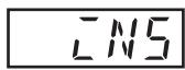
Temperature Input Shift
- With a 1-point shift, the value set for the Temperature Input Shift parameter (adjustment level) is applied to each point in the entire temperature input range. For example, if the input shift value is set to 1.2^ , the process value is treated as 201.2^ after the input shift is applied when the measured process value is 200^ .
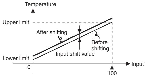
Operating Procedure
In this example, the input from a K sensor is shifted by 1^ using a 1-point input shift.
Operation Level
Operation Level
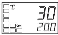
Adjustment Level
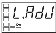
Adjustment Level Display
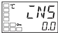
Temperature Input Shift
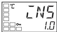
Operation Level
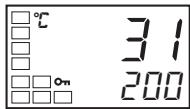
- Press the l Key to move from the operation level to the adjustment level.
- Select the Temperature Input Shift parameter by pressing the Key.
- Press the 心 or 心 Key to set 1.0.
- To return to the operation level, press the Key. The process value is 1^ larger than before the shift was applied.
Two-point shift
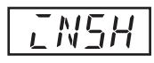
Upper-limit Temperature Input Shift Value
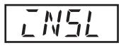
Lower-limit Temperature Input Shift Value
- Separate shift values can be set for the upper limit and lower limit of the sensor input range for an infrared sensor as well as for a thermocouple or platinum resistance thermometer with the Input Shift Type parameter set to INS2. If different shift values are set for the upper limit and lower limit, then the slope of the line will be different before and after applying the input shift. For example, if the upper-limit value is set to 2^ and the lower-limit value is set to 1^ , the input temperature will be shifted by 1.5^ for a 50% input, i.e., by the average of the upper-limit and lower-limit values.
- Set the upper-limit value in the Upper-limit Temperature Input Shift Value parameter and the lower-limit value in the Lower-limit Temperature Input Shift Value parameter.
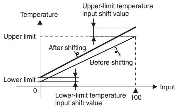
4-1-2 How to Calculate Input Shift Values for a 2-point Shift
When an ES1B Infrared Temperature Sensor is connected to the E5CN, an offset of several degrees to several tens of a degree can occur.
For this reason, offset the readout value using a 1-point or 2-point shift as described in this section. This offset occurs because a bias current for detecting a Controller sensor error flows to the output impedance of the infrared temperature sensor.
Preparations
1,2,3...
- Set a temperature range matching the input specifications of the infrared temperature sensor. (The ES1B can be used with the E5☐N only for a thermocouple/resistance thermometer universal input.)
- Prepare a thermometer capable of measuring the temperature of the control target as shown in Figure 1 so that a 1-point shift or 2-point shift can be carried out.
- The E53-CN□□P□N2 (for E5CN), E5AN-□□P□-N, or E5EN-□□P□-N has a built-in external power supply for ES1B Infrared Temperature Sensors. These E5CN models can be used as the power supply when using ES1B. When ES1B are used with other E5CN models, provide a separate power supply for the Infrared Temperature Sensors.
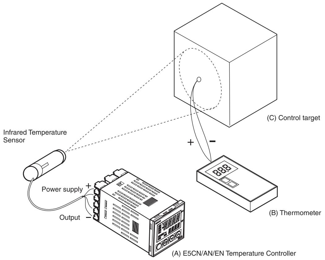
Figure 1 Offset Configuration for an Infrared Temperature Sensor
Method for a 1-point Shift
1,2,3...
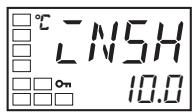
Upper-limit Temperature Input Shift Value
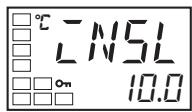
Lower-limit Temperature Input Shift Value
- In the configuration shown in Figure 1, bring the set point to near the value at which the temperature of the control target is to be controlled. Assume that the control target temperature (C) and the thermometer temperature (B) are the same.
- Check the thermometer temperature (B) and the Controller readout (A). Subtract the Controller readout temperature (A) from the thermometer temperature (B), and set N5L and N5H to the result as the input shift value. The shift is illustrated in Figure 2.
- After setting the input shift values, check the Controller readout (A) and the thermometer temperature (B). If they are almost the same, this completes shifting the temperature input.
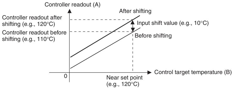
Figure 2 Illustration of 1-Point Shift
Method for a 2-point Shift
Use a 2-point input shift if you want to increase the accuracy of the readout values across the range of the Sensor.
1,2,3...
- Shift the Controller readout at two points, near room temperature and near the value at which the temperature of the control target is to be controlled. For this reason, check the thermometer temperature (B) and Controller readout (A) with the thermometer temperature near room temperature and near the set point.
2.
- Y1 is the Controller readout at room temperature before shifting and X1 is the Controller readout at room temperature after shifting.
- Y2 is the Controller readout at the set temperature before shifting and X2 is the Controller readout at the set temperature after shifting.
- Set the upper-limit temperature input shift and the lower-limit temperature input shift using the following formulas based on the temperatures before shifting (Y1 and Y2), the temperatures after shifting (X1 and X2), the set temperature upper limit (YH), and the set temperature lower limit (YL). The shift is illustrated in Figure 3.
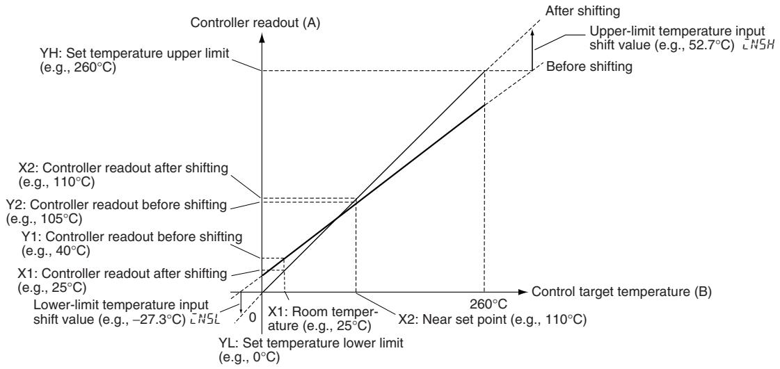
Figure 3 Illustration of 2-Point Shift
a. Lower-limit temperature input shift value
$$ \bar {L} N 5 L = \frac {Y L - Y 1}{Y 2 - Y 1} \times \left{\left(X 2 - Y 2\right) - \left(X 1 - Y 1\right) \right} + \left(X 1 - Y 1\right) $$
b. Upper-limit temperature input shift value
$$ \bar {L} N 5 H = \frac {Y H - Y 1}{Y 2 - Y 1} \times \left{\left(X 2 - Y 2\right) - \left(X 1 - Y 1\right) \right} + \left(X 1 - Y 1\right) $$
- After setting the calculated values to N5L and N5H , check the Controller readout (A) and thermometer temperature (B).
- Here, offsets are set at two points, near room temperature and near the set point. To improve accuracy within the measurement temperature range, another point in the measurement temperature range other than the set point should be set instead of room temperature.
Example of a 2-point Temperature Input Shift
In this example, we use the ES1B K 0 to 260^ specification. In equations 1 and 2, the set temperature lower limit YL is 0^ and the set temperature upper limit YH is 260^ . Check the temperature of the control target.
The temperature input offset values can be calculated as shown below when the Controller readout Y1 is 40^ for a room temperature X1 of 25^ and when the Controller readout Y2 is 105^ for a set point temperature X2 of 110^ .
Lower-limit Temperature Input Shift Value
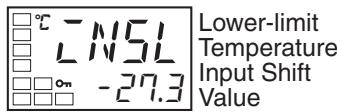
$$ \bar {L} N 5 L = \frac {0 - 4 0}{1 0 5 - 4 0} \times {(1 1 0 - 1 0 5) - (2 5 - 4 0) } + (2 5 - 4 0) = - 2 7. 3 (\mathrm {^ {\circ} C}) $$
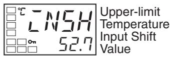
Upper-limit Temperature Input Shift Value
$$ \bar {N} 5 H = \frac {2 6 0 - 4 0}{1 0 5 - 4 0} \times {(1 1 0 - 1 0 5) - (2 5 - 4 0) } + (2 5 - 4 0) = 5 2. 7 (^ {\circ} C) $$
4-2 Alarm Hysteresis
- The hysteresis of alarm outputs when alarms are switched ON/OFF can be set as follows:
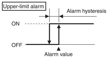
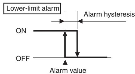
- Alarm hysteresis is set independently for each alarm in the Alarm Hysteresis 1 to Alarm Hysteresis 3 parameters (initial setting level).
- The default is 0.2(^ / ^) for Controllers with Thermocouple/Resistance Thermometer Universal Inputs and 0.02% FS for Controllers with Analog Inputs.
4-2-1 Standby Sequence
- The standby sequence can be used so that an alarm will not be output until the process value leaves the alarm range once and then enters it again.
- For example, with a lower limit alarm, the process value will normally be below the set point, i.e., within the alarm range, when the power supply is turned ON, causing an alarm to be output.
If the lower limit alarm with a standby sequence is selected, an alarm will not be output until the process value increases above the alarm set value, i.e., until it leaves the alarm range, and then falls back below the alarm set value.
Restart
- The standby sequence is canceled when an alarm is output. It is, however, restarted later by the Standby Sequence Reset parameter (advanced function setting level). For details, refer to the Standby Sequence Reset parameter in SECTION 5 Parameters.
4-2-2 Alarm Latch
- The alarm latch can be used to keep the alarm output ON until the latch is canceled regardless of the temperature once the alarm output has turned ON.
Any of the following methods can be used to clear the alarm latch.
- Turn OFF the power supply. (The alarm latch is also cleared by switching to the initial setting level, communications setting level, advanced function setting level, or calibration level.)
- Use the PF Key.
- Use an event input.
For details on setting the PF Key, refer to 4-19 Setting the PF Key. For details on setting events, refer to 4-5 Using Event Inputs.
Summary of Alarm Operation
The following figure summarizes the operation of alarms when the Alarm Type parameter is set to "lower-limit alarm with standby sequence" and "close in alarm" is set.
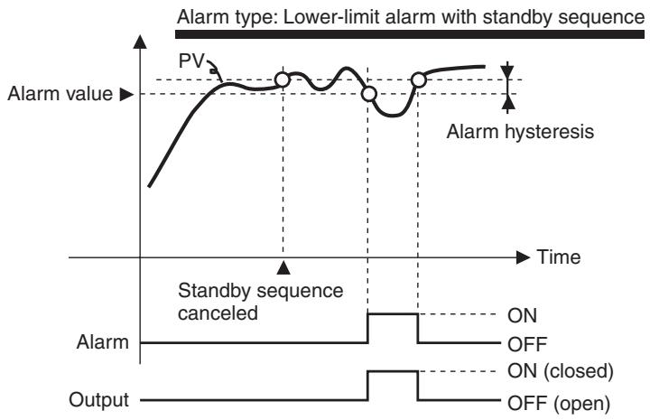
Parameters
| Symbol | Parameter: level | Description |
| RLH* | Alarm 1 to 3 Hysteresis: Initial setting level | Alarm |
| RE5E | Standby Sequence: Advanced function setting level | Alarm |
Note * = 1 to 3
4-3 Setting Scaling Upper and Lower Limits for Analog Inputs
4-3-1 Analog Input

Scaling Upper Limit

Scaling Lower Limit
Decimal Point
- When an analog input is selected, scaling can be performed as needed by the control application.
- Scaling is set in the Scaling Upper Limit, Scaling Lower Limit, and Decimal Point parameters (initial setting level). These parameters cannot be used when a temperature input is selected.
-
The Scaling Upper Limit parameter sets the physical quantity to be expressed by the upper limit value of input, and the Scaling Lower Limit parameter sets the physical quantity to be expressed by the lower-limit value of input. The Decimal Point parameter specifies the number of digits below the decimal point.
-
The following figure shows a scaling example for a 4 to 20mV input. After scaling, the humidity can be directly read. Here, one place below the decimal point is set.
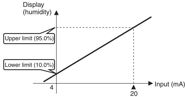
Operating Procedure
Initial Setting Level
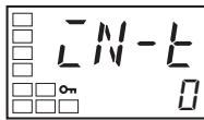
Input Type
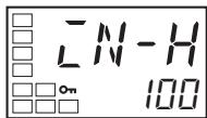
Scaling Upper Limit
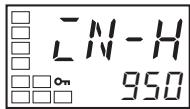
Scaling Lower Limit
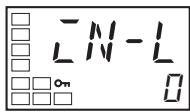

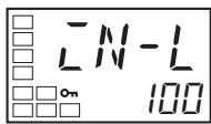
Decimal Point
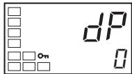

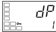
In this example scaling is set to display 4 to 20mA as 10.0% to 95.0% .
- Press the Key for three seconds to move from the operation level to the initial setting level.
- Select Scaling Upper Limit parameter by pressing the Key.
- Use the and Keys to set the parameter to 950.
- Select the Scaling Lower Limit parameter by pressing the Key.
- Press the and Keys to set 100.
- Select the Decimal Point parameter by pressing the
- Press the and Keys to set 1.
- To return to the operation level, press the Key for one second.
4-4 Executing Heating/Cooling Control
4-4-1 Heating/Cooling Control
Heating/cooling control can be used on the E5CN-□M□-500 (with an E53-CNQ□□N2), E5CN-□2M□-500, E5AN-□3M□-500-N or E5EN-□3M□-500-N. Heating/cooling control operates when H - L (heating/cooling) is selected for the Standard or Heating/Cooling parameter.
The following functions are assigned to outputs in the initial status.
| Parameter name | Symbol | Initial status |
| Control Output 1 Assignment | aUb1 | Control output for heating |
| Control Output 2 Assignment | aUb2 | Not assigned. |
| Auxiliary Output 1 Assignment | 5Ub1 | Alarm 1 |
| Auxiliary Output 2 Assignment | 5Ub2 | Alarm 2 |
| Auxiliary Output 3 Assignment (E5AN/EN only) | 5Ub3 | Alarm 3 |
Each output assignment is automatically initialized as shown below when the control mode is changed.
Example: E5CN
| Parameter name | Symbol | Without control output 2 | With control output 2 | ||
| Standard | Heating/cooling | Standard | Heating/cooling | ||
| Control Output 1 Assignment | \( \bar{a} u_{\text{E}} \) | Control output (heating) | Control output (heating) | Control output (heating) | Control output (heating) |
| Control Output 2 Assignment | \( \bar{a} u_{\text{E}} \) | Not assigned. (See note 1.) | Not assigned. (See note 1.) | Not assigned. | Control output (coo-ing) |
| Auxiliary Output 1 Assignment | \( \bar{S} u_{\text{B}} \) | Alarm 1 (See note 2.) | Alarm 1 (See note 2.) | Alarm 1 (See note 2.) | Alarm 1 (See note 2.) |
| Auxiliary Output 2 Assignment | \( \bar{S} u_{\text{B}} \) | Alarm 2 (See note 3.) | Control output (coo-ing) (See note 3.) | Alarm 2 | Alarm 2 |
Example: E5GN
| Parameter name | Symbol | Standard | Heating/cooling |
| Control Output 1 Assignment | \( \bar{a}U_{\text{ct}} \) | Control output (heating) | Control output (heating) |
| Auxiliary Output 1 Assignment | \( \bar{S}U_{\text{ct}} \) | Alarm 1 (See note 2.) | Control output (coo-ing) |
| Auxiliary Output 2 Assignment | \( \bar{S}U_{\text{ct}} \) | Alarm 2 | Alarm 2 |
Note
(1) No parameter assignment is displayed because there is no control output 2.
(2) The output set for the Auxiliary Output 1 Assignment parameter becomes the program END output unless the program pattern is OFF.
(3) For the E5AN/EN, the Auxiliary Output 3 Assignment parameter is set for control output (cooling) (the Auxiliary Output 2 Assignment parameter is set for alarm 2).
- The heating/cooling operation of the control outputs will switch when the Direct/Reverse Operation parameter is set to "direct."
- When DRS (Invert Direct/Reverse Operation) is assigned for an Event Input Assignment (1 or 2), control will start with the contents set for the Direct/Reverse Operation parameter inverted when the event input turns ON, and with the contents left according to the setting when the event input turns OFF. For details on event inputs and control combined with the Direct/Reverse Operation parameter, refer to Control by Inverting Direct/ Reverse Operation on page 103.
- When heating/cooling control is selected, the Dead Band and Cooling Coefficient parameters can be used.
Dead Band
- For heating/cooling control, the dead band is set with the set point as its center. The dead band width is the set value of the Dead Band parameter (adjustment level). Setting a negative value produces an overlapping band.
- If an overlapping band is set, the bumpless function may not operate when switching between manual operation and automatic operation.
- The default is 0.0 EU for Controllers with Thermocouple/Resistance Thermometer Universal Inputs and 0.00% FS for Controllers with Analog Inputs.
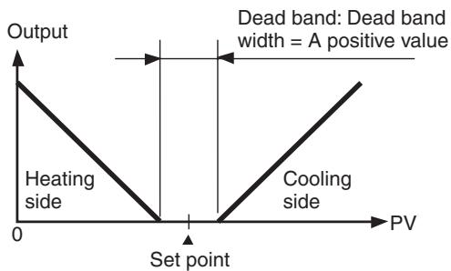
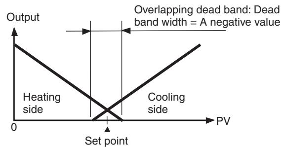
Cooling Coefficient
If the heating characteristics and cooling characteristics of the control object are very different and good control characteristics cannot be achieved with the same PID constants, the cooling coefficient can be used to adjust the proportional band (P) for the control output assigned to the cooling side. Use this to achieve balanced control between the heating side and cooling side. The proportional bands (P) for the control outputs assigned to the heating/cooling sides can be calculated using the following equations.
P for control output assigned to heating side =
P for control output assigned to cooling side = P for control output assigned to heating side × cooling coefficient
The cooling coefficient is multiplied by the P for the control output assigned to the heating side to obtain control with characteristics that differ from those of the control output assigned to the heating side.
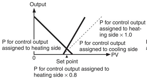
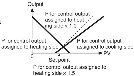
Automatic Cooling Coefficient Adjustment
By executing AT during heating/cooling control, the cooling coefficient can be automatically calculated along with the PID parameters.
| Parameter name | Setting rage | Default |
| Automatic Cooling Coefficient Adjustment | OFF: Disabled, ON: Enabled | OFF |
Note
If there is strong non-linear gain for the cooling characteristics, such as when cooling water boils for cooling control, it may not be possible to obtain the optimum cooling coefficient at the Controller, and control may take the form of
oscillating waves. If that occurs, increase the proportional band or the cooling coefficient to improve control.
4-4-2 Settings
To set heating/cooling control, set the Standard or Heating/Cooling, Dead Band, and Cooling Coefficient parameters.
Setting Heating/Cooling Control
Operating Procedure
Initial Setting Level

Standard or Heating/ Cooling
Standard or heating/cooling = Heating/cooling
-
Press the Key for at least three seconds to move from the operation level to the initial setting level.
-
Select "heating/cooling control" in the initial setting level.
5kNd: Standard control
H-E: Heating/cooling control
Setting the Cooling Coefficient
Operating Procedure
Adjustment Level
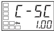
Cooling Coefficient
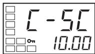
Cooling Coefficient = 10
-
Select the Cooling Coefficient parameter in the adjustment level.
-
Use the Key to set the parameter to 10.00.
Setting the Dead Band
Operating Procedure
Adjustment Level
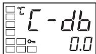
Dead Band
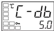
Dead Band = 5
-
Select the Dead Band parameter in the adjustment level.
-
Use the Key to set the parameter to 5.0.
4-5 Using Event Inputs
4-5-1 Event Input Settings
-
Event inputs can be used for Multi-SP, RUN/STOP, Auto/Manual Switch, Program Start, Invert Direct/Reverse Operation, 100% AT Execute/Cancel, 40% AT Execute/Cancel, Setting Change Enable/Disable, and Alarm Latch Cancel.
-
Of these, only the number of event inputs (0 to 2) set in the Number of Multi-SP Uses parameter (initial setting level) are used for the multi-SP function.
-
Of these, only the number of event inputs (0 to 2) set in the Number of Multi-SP Uses parameter (initial setting level) are automatically assigned by the multi-SP function. Displays for event input assignments will not be displayed for inputs that are automatically assigned by the multi-SP function. Event inputs 1 and 2 are used for the multi-SP function by models with four event inputs.
Event inputs can be used on the following models: E5CN- M□-500 with the E53-CN□B□N2 for the E5CN E5AN/EN- M□-500-N with the E53-AKB for the E5AN/EN
-
When using event inputs to switch the multi-SP, the event input assignment display will not appear. Whether the set value and event input assignments 1 and 2 will be displayed or hidden is shown in the tables below.
-
Do not connect the contacts from the same switch to more than one E5□N Controllers.
Models with Two Event Inputs, 1 and 2
| Event input assignment 1 | Event input assignment 2 | Description of EV1 and EV2 operation | ||
| Number of Multi-SP Uses | 0 | Displayed (Multi-SP not used). | EV1 and EV2 will perform the operation command assigned using the Event Input Assignment 1 and 2 parameters. | |
| 1 | Not displayed (Operation performed with two Multi-SP points.) | Displayed (Event input 2 not used as multi-SP switch). | EV1 will be used for the Multi-SP function to switch between set points 0 and 1. EV2 will perform the operation command assigned using the Event Input Assignment 2 parameter. | |
| 2 | Not displayed (Operation performed with four Multi-SP points.) | EV1 and EV2 will be used for the Multi-SP function to switch between set points 0, 1, 2, and 3. | ||
Models with Two Event Inputs, 3 and 4
| Event input assignment 3 | Event input assignment 4 | Description of EV3 and EV4 operation | ||
| Number of Multi-SP Uses | 0 | Displayed (Multi-SP not used). | EV3 and EV4 will perform the operation command assigned using the Event Input Assign-ment 3 and 4 parameters. | |
| 1 | Not displayed (Operation per-formed with two Multi-SP points.) | Displayed (Event input 4 not used as multi-SP switch). | EV3 will be used for the Multi-SP function to switch between set points 0 and 1. EV4 will perform the operation com-mand assigned using the Event Input Assignment 2 parameter. | |
| 2 | Not displayed (Operation performed with four Multi-SP points.) | EV3 and EV4 will be used for the Multi-SP function to switch between set points 0, 1, 2, and 3. | ||
Models with Four Event Inputs, 1 to 4
| Event input assignment 1 | Event input assignment 2 | Event input assignment 3 | Event input assignment 4 | Description of EV1, EV2, EV3, and EV4 operation | ||
| Number of Multi-SP Uses | 0 | Displayed (Multi-SP not used). | EV1, EV2, EV3, and EV4 will perform the operation command assigned using the Event Input Assignment 1, 2, 3, and 4 parameters. | |||
| 1 | Not displayed (Operation performed with two Multi-SP points.) | Displayed (Event inputs 2, 3, and 4 cannot be used for multi-SP switching.) | EV1 will be used for the Multi-SP function to switch between set points 0 and 1. EV2, EV3, and EV4 will perform the operation command assigned using the Event Input Assignment 2, 3, and parameters. | |||
| 2 | Not displayed (Operation performed with four Multi-SP points.) | Displayed (Event inputs 3 and 4 cannot be used for multi-SP switching.) | EV1 and EV2 will be used for the Multi-SP function to switch between set points 0, 1, 2, and 3. EV3 and EV4 will perform the operation command assigned using the Event Input Assignment 3 and 4 parameters. | |||
Two set points are set externally by using the Number of Multi-SP Uses parameter.
- Switching is possible between two set points (0 and 1) by setting the Number of Multi-SP Uses parameter to 1. The default setting is 1 and does not need to be changed to switch between two set points. Set points 0 and 1 are specified by the status of event input 1.
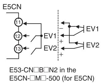
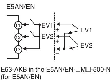
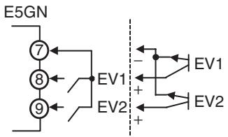
4-5-2 How to Use the Multi-SP Function
The multi-SP function allows you to set up to four set points (SP 0 to 3) in the adjustment level. The set point can be switched by operating the keys on the front panel or by using external input signals (event inputs).
Using Event Inputs
Two Event Inputs: Event Inputs 1 and 2
The following tables show the relationship between the ON/OFF combinations of event inputs 1 and 2 and the selected set points.
Number of Multi-SP Uses = 1
| Event input 1 | Selected set point |
| OFF | Set point 0 |
| ON | Set point 1 |
Number of Multi-SP Uses = 2
| Event input 1 | Event input 2 | Selected set point |
| OFF | OFF | Set point 0 |
| ON | OFF | Set point 1 |
| OFF | ON | Set point 2 |
| ON | ON | Set point 3 |
Using Key Operations
You can select any of the set points 0 to 3 by changing the set value of the Multi-SP Uses parameter. The Multi-SP Uses parameter display conditions are as follows:
- If the Controller does not support event inputs, the Multi-SP Uses parameter must be set to ON.
- If the Controller supports event inputs, the Number of Multi-SP Uses parameter must be set to 0 and the Multi-SP Uses parameter must be set to ON.
The following table shows the relationship between the Multi-SP Uses parameter set value and the selected set point.
| Multi-SP | Selected set point |
| 0 | Set point 0 |
| 1 | Set point 1 |
| 2 | Set point 2 |
| 3 | Set point 3 |
Note The set point can also be switched using communications.
4-5-3 Settings
Switching between Set Points 0, 1, 2, and 3
Operating Procedure
Operation Level
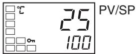
The following example sets the Number of Multi-SP Uses parameter to 2.
- Press the Key for at least three seconds to move from the operation level to the initial setting level.
Number of Multi-SP Uses Setting
- Select the Number of Multi-SP Uses parameter by pressing the Key.
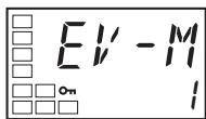
Number of Multi-SP Uses
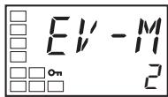
- Use the Key to set the parameter to 2.
Set points 0, 1, 2 and 3 will be set according to the ON/OFF states of event inputs 1 and 2.
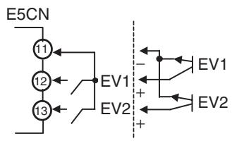
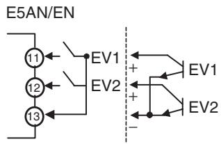
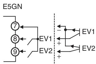
4-5-4 Operation Commands Other than Multi-SP
The following table shows the functions assigned when an Event Input Assignment (1 or 2) is displayed.
| Setting | Function |
| None | None |
| STOP | RUN/STOP |
| MANU | Auto/Manual |
| PRST | Program Start (See note 1.) |
| dRS | Invert Direct/Reverse Operation |
| RE -2 | 100% AT Execute/Cancel |
| RE -1 | 40% AT Execute/Cancel (See note 2.) |
| WEPE | Setting Change Enable/Disable |
| LRE | Alarm Latch Cancel |
Note
(1) PRST (Program Start) can be set even when the Program Pattern parameter is set to OFF, but the function will be disabled.
(2) This function can be set for heating/cooling control, but the function will be disabled.
When any of the following functions is set for an Event Input Assignment parameter, the same function cannot be set for another Event Input Assignment parameter: STOP (RUN/STOP), MANU (Auto/Manual Switch), PRST (Program Start), DRS (Invert Direct/Reverse Operation), AT-2 (100% AT Execute/Cancel), AT-1 (40% AT Execute/Cancel), WTPT (Setting Change Enable/Disable), or LAT (Alarm Latch Cancel). Turn event inputs ON and OFF while the power is being supplied. Event input ON/OFF changes are detected for inputs of 50 ms or longer. (However, inputs of 250 ms or longer is determined using logic operations.)
The functions are described in detail below. Event inputs 1 and 2 are taken as examples.
Executing Run/Stop Control
When the Event Input Assignment 1 or Event Input Assignment 2 parameter is set to STOP (RUN/STOP), control is started when event input 1 or 2 turns OFF. Control is stopped when the input turns ON. Alarm outputs, however, will be according to the process value.
The STOP indicator will light while control is stopped.
| Setting | Input contact | Status |
| Event input 1 or 2 | ON | STOP |
| Event input 1 or 2 | OFF | RUN |
Switching between Auto and Manual Control
When the Event Input Assignment 1 or Event Input Assignment 2 parameter is set to MANU (auto/manual), manual control will start when event input 1 or 2 turns ON. Auto control will start when the input turns OFF.
The MANU indicator will light during manual control.
| Setting | Input contact | Status |
| Event input 1 or 2 | OFF | Automatic |
| Event input 1 or 2 | ON | Manual |
Controlling the Start of the Simple Program Function
When the Event Input Assignment 1 or Event Input Assignment 2 parameter is set to PRST (program start), the program will start when event input 1 or 2 turns ON. The program will be reset when the input turns OFF and the RUN/ STOP status will automatically switch to STOP mode. If the program END output is ON, the program END output will turn OFF.
| Setting | Input contact | Status |
| Event input 1 or 2 | OFF | Reset |
| Event input 1 or 2 | ON | Start |
Control by Inverting Direct/Reverse Operation
When DRS (Invert Direct/Reverse Operation) is set for the Event Input Assignment 1 or Event Input Assignment 2 parameter and the Direct/Reverse Operation parameter is set for reverse operation, control starts with direct operation (cooling control) when event input 1 or 2 turns ON and control starts with reverse operation (heating control) when the event input turns OFF.
| Setting | Input contact | Direct/Reverse Operation parameter | Status |
| Event input 1 or 2 | OFF | Direct operation (cooling) | Direct operation (cooling) |
| Reverse operation (heating) | Reverse operation (heating) |
Switching 100% AT Execute/Cancel
| Setting | Input contact | Direct/Reverse Operation parameter | Status |
| Event input 1 or 2 | ON | Direct operation (cooling) | Reverse operation (heating) |
| Reverse operation (heating) | Direct operation (cooling) |
When AT-2 (100% AT Execute/Cancel) is set for either the Event Input Assignment 1 or Event Input Assignment 2 parameter, 100% AT will be executed when event input 1 or 2 turns ON and will be cancelled when the input turns OFF.
Switching 40% AT Execute/Cancel
| Setting | Input contact | Status |
| Event input 1 or 2 | OFF | 100% AT cancelled |
| Event input 1 or 2 | ON | 100% AT executed |
When AT-1 (40% AT Execute/Cancel) is set for either the Event Input Assignment 1 or Event Input Assignment 2 parameter, 40% AT will be executed when event input 1 or 2 turns ON and will be cancelled when the input turns OFF.
| Setting | Input contact | Status |
| Event input 1 or 2 | OFF | 40% AT cancelled |
| Event input 1 or 2 | ON | 40% AT executed |
Switching Setting Change Enable/ Disable
When WTPT (Setting Change Enable/Disable) is set for either the Event Input Assignment 1 or Event Input Assignment 2 parameter, the setting change will be disabled when event input 1 or 2 turns ON and will be enabled when the input turns OFF.
| Setting | Input contact | Status |
| Event input 1 or 2 | OFF | Enabled |
| Event input 1 or 2 | ON | Disabled |
Switching Alarm Latch Cancel
When LAT (Alarm Latch Cancel) is set for either the Event Input Assignment 1 or Event Input Assignment 2 parameter, all alarm latches (alarms 1 to 3, heater burnout, HS alarm, and heater overcurrent latch) will be cancelled when event input 1 or 2 turns ON.
| Setting | Input contact | Status |
| Event input 1 or 2 | OFF | --- |
| Event input 1 or 2 | ON | Cancelled |
Parameters
| Symbol | Parameter: level | Description |
| EV-1 | Event Input Assignment 1: Initial setting level | Function of event input function |
| EV-2 | Event Input Assignment 2: Initial setting level | |
| EV-M | Number of Multi-SP Uses: Initial setting level |
4-6 Setting the SP Upper and Lower Limit Values
4-6-1 Set Point Limiter
The setting range of the set point is limited by the set point limiter. This function can be used to prevent setting incorrect process values. The set point limiter is used to prevent the control target from reaching abnormal temperatures. If the set point is not within the range set for the set point limiter as the result of changes to the Set Point Upper Limit or Set Point Lower Limit parameter, the set point will automatically be change to a value within the set
range. The upper- and lower-limit values of the set point limiter are set using the Set Point Upper Limit and Set Point Lower Limit parameters in the initial setting level. When the set point limiter is reset, the set point is forcibly changed to the upper- or lower-limit value of the set point limiter if the set point is out of the limiter range. Also, when the input type and the temperature unit, scaling upper-limit value, or lower-limit value are changed, the set point limiter is forcibly reset to the input setting range or the scaling upper- or lower-limit value.
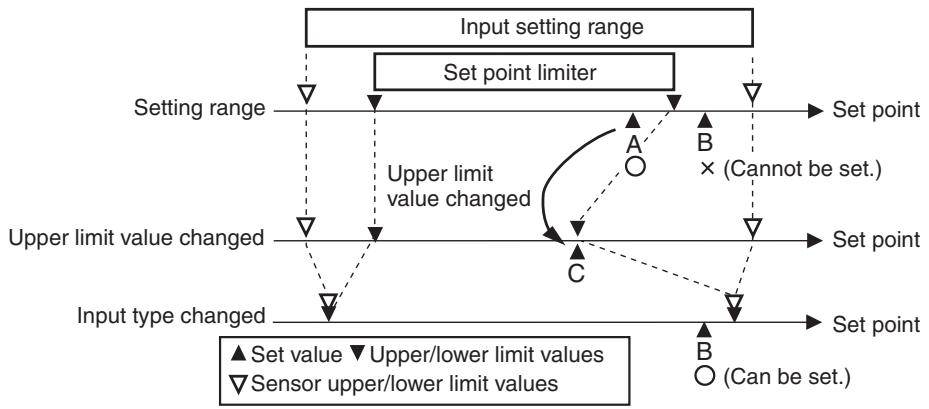
Parameters
| Symbol | Parameter: level | Description |
| SL-H | Set Point Upper Limit: Initial setting level | To limit the SP setting |
| SL-L | Set Point Lower Limit: Initial setting level | To limit the SP setting |
4-6-2 Setting
Set the set point upper and lower limits in the Set Point Upper Limit and Set Point Lower Limit parameters in the initial setting level. In this example, it is assumed that the input type is set to a K thermocouple with a temperature range of -200 to 1300^ .

Setting the Set Point Upper-limit Value
Operating Procedure
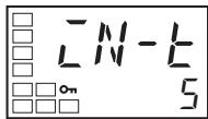
Input Type
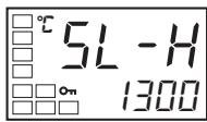
Set Point Upper-limit
Set Point Upper Limit = 1000
- Press the Key for at least three seconds to move from the operation level to the initial setting level.
- Select the Set Point Upper Limit parameter.
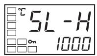
- Use the and Keys to set the parameter to 1000.
Setting the Set Point Lower-limit Value
Operating Procedure
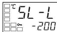
Set Point Lower Limit
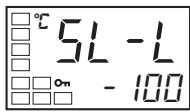
Set Point Lower Limit = -100
-
Select the Set Point Lower Limit parameter in the initial setting level.
-
Use the and Keys to set the parameter to -100.
4-7 Using the SP Ramp Function to Limit the SP Change Rate 4-7-1 SP Ramp
The SP ramp function is used to restrict the width of changes in the set point as a rate of change. When the SP ramp function is enabled and the change width exceeds the specified rate of change, an area where the set point is restricted will be created, as shown in the following diagram.
During the SP ramp, control will be performed not for the specified set point but rather for the set point restricted by the rate of change set for the SP ramp function.
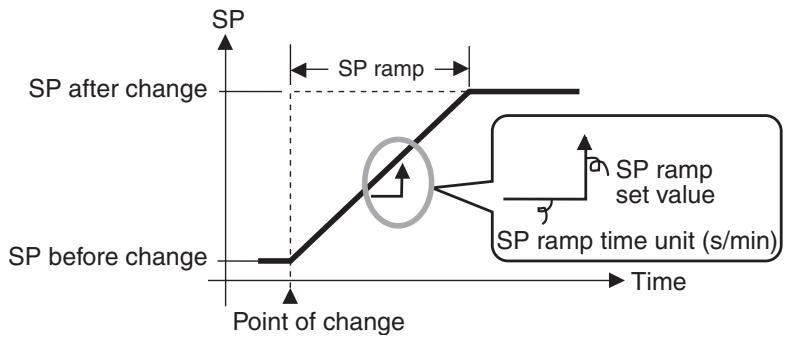
The rate of change during SP ramp is specified using the SP Ramp Set Value and SP Ramp Time Unit parameters. The SP Ramp Set Value parameter is set to OFF by default, i.e., the SP ramp function is disabled.
Changes in the ramp set point can be monitored in the Set Point During SP Ramp parameter (operation level). Use this parameter when monitoring SP ramp operation.
The SP ramp function operates in the same way when switching the set point using the multi-SP function.
Parameters
| Symbol | Parameter: level | Description |
| \( \overline{\mathsf{a}}\mathsf{L}-\mathsf{H} \) | MV Upper Limit: Adjustment level | To limit the manipulated variable |
| \( \overline{\mathsf{a}}\mathsf{L}-\mathsf{L} \) | MV Lower Limit: Adjustment level | To limit the manipulated variable |
| \( \overline{\mathsf{S}}\mathsf{L}-\mathsf{H} \) | Set Point Upper Limit: Initial setting level | To limit the SP setting |
| \( \overline{\mathsf{S}}\mathsf{L}-\mathsf{L} \) | Set Point Lower Limit: Initial setting level | To limit the SP setting |
| \( \overline{\mathsf{SP}}\overline{\mathsf{R}}\overline{\mathsf{E}} \) | SP Ramp Set Value: Adjustment level | To limit the SP rate of change |
| \( \overline{\mathsf{SP}}\overline{\mathsf{R}}\overline{\mathsf{U}} \) | SP Ramp Time Unit: Advanced function setting level | Unit for setting the SP |
| \( \overline{\mathsf{RL}}\overline{\mathsf{SP}} \) | Alarm SP Selection: Advanced function setting level | Alarm SP selection |
Operation at Startup
If the SP ramp function is enabled when the Controller is turned ON or when switching from STOP to RUN mode, the process value reaches the set point using the SP ramp function in the same way as when the set point is changed. In this case, operation is carried out with the process value treated as the set point before the change was made. The direction of the SP ramp changes according to the relationship between the process value and the set point.
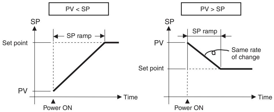
Restrictions during SP Ramp Operation
- Execution of auto-tuning starts after the end of the SP ramp.
- When control is stopped or an error occurs, the SP ramp function is disabled.
Alarms during SP Ramp Operation
The operation of alarms during SP ramp operation depends on whether alarms are set to be based on the ramp set point or the target set point (refer to the following diagrams). The set point to be used is set in the Alarm SP Selection parameter. (Refer to page 244.)
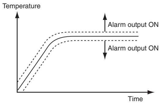
Alarm SP Selection = Ramp SP (Alarm Type: 1 (Upper/Lower Limits))
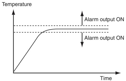
Alarm SP Selection = Target SP (Alarm Type: 1 (Upper/Lower Limits))
4-8 Moving to the Advanced Function Setting Level
To move to the advanced function setting level, you must first cancel the protection applied by the Initial Setting/Communications Protect parameter.
In the default setting, the advanced function setting level is protected and you cannot move to this setting level.
1,2,3... 1. Press the and Keys simultaneously for at least three seconds in operation level.
Note The key pressing time can be changed in the Move to Protect Level Time parameter (advanced function setting level).
Protect Level
Operation/Adjustment Protect
Initial Setting/Communications Protect
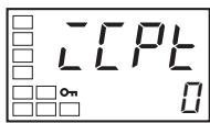
- The Controller moves to the protect level, and the Operation/Adjustment Protect parameter is displayed.
- Press the Key once to move to the Initial Setting/Communications Protect parameter.
- Set the set value to 0.
Operation Level

Initial Setting Level
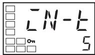
Input Type
Initial Setting Level
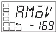
Move to Advanced Function Setting Level
Advanced function setting level
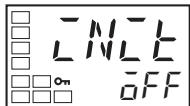
Parameter Initialization
Initial Setting Level
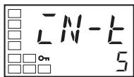
Input Type
Operation Level
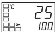
PV/SP
- Press the and Keys simultaneously for at least one second to return to the operation level.
- Move to the advanced function setting level.
Press the Key for at least three seconds to move from the operation level to the initial setting level.
- Select the Move to Advanced Function Setting Level parameter by pressing the 回 Key.
- Press the Key, enter the password (-169), and then either press the Key or leave the setting for at least two seconds to move to the advanced function setting level from the initial setting level.
- To return to the initial setting level, press the Key for at least one second.
- To return to the operation level, press the Key for at least one second.
4-9 Using the Key Protect Level
4-9-1 Protection
- To move to the protect level, press the and Keys simultaneously for at least three seconds in operation level or adjustment level. (See note.)
Note The key pressing time can be changed in the Move to Protect Level Time parameter (advanced function setting level). - The protect level protects parameters that are not changed during Controller operation until operation is started to prevent them from being modified unintentionally.
There are four types of protection: operation/adjustment protect, initial setting/communications protect, setting change protect, and PF Key protect. - The protect level settings restrict the range of parameters that can be used.
Operation/Adjustment Protect
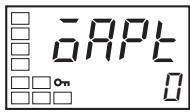
The following table shows the relationship between set values and the range of protection.
| Level | Set value | ||||
| 0 | 1 | 2 | 3 | ||
| Operation level | PV | Can be dis-played | Can be dis-played | Can be dis-played | Can be dis-played |
| PV/SP | Can be dis-played and changed | Can be dis-played and changed | Can be dis-played and changed | Can be dis-played | |
| Others | Can be dis-played and changed | Can be dis-played and changed | Cannot be displayed and moving to other levels is not possible | Cannot be displayed and moving to other levels is not possible | |
| Adjustment level | Can be dis-played and changed | Cannot be displayed and moving to other levels is not possible | Cannot be displayed and moving to other levels is not possible | Cannot be displayed and moving to other levels is not possible | |
- Parameters are not protected when the set value is set to 0.
- The default is 0.
Initial Setting/ Communications Protect
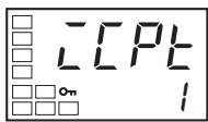
This protect level restricts movement to the initial setting level, communications setting level, and advanced function setting level.
| Set value | Initial setting level | Communications setting level | Advanced function setting level |
| 0 | Possible to reach | Possible to reach | Possible to reach |
| 1 | Possible to reach | Possible to reach | Not possible to reach |
| 2 | Not possible to reach | Not possible to reach | Not possible to reach |
- The default is 1.
Setting Change Protect
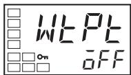
This protect level restricts key operations.
| Set value | Description |
| OFF | Settings can be changed using key operations. |
| ON | Settings cannot be changed using key operations. (The protect level settings, however, can be changed.) |
- The default is OFF.
- The all protect indication (Oπ) will light when setting change protect is set.
PF Key Protect
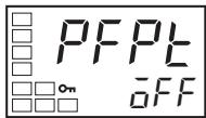
This protect level enables or disables PF Key operations.
| Set value | Description |
| OFF | PF Key enabled. |
| ON | PF Key disabled (Operation as function key prohibited). |
- The default is OFF.
4-9-2 Entering the Password to Move to the Protect Level
- Protect level can be moved to only by display the password display and entering the correct password. (The user can set any password in the Protect Level Password parameter. If no password is set (i.e., if the password is set to 0 in the Protect Level Password parameter), the password input display to move to protect level will not be displayed and the protect level can be moved to directly.
Operating Procedure
Use the following procedure to move to protect level.
Example with a Password of 1234
Operation Level
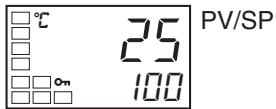
Protect Level
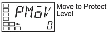
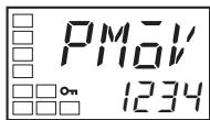
Protect Level
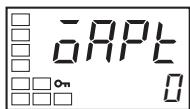
Operation/Adjustment Protect
- Press the and Keys simultaneously for at least the time set in the Move to Protect Level Time parameter to move from the operation level to the protect level.
- Press the Key to set the parameter to 1234 (password input).
- Move to the Operation/Adjustment Protect parameter by pressing the or Key or leaving the setting for at least two seconds.
Example with No Password Set
Operation Level

Protect Level

Operation/Adjustment Protect
Press the and Keys simultaneously for at least the time set in the Operation/Adjustment Protect parameter to move from the operation level to the protect level.
When a password is not set, the Operation/Adjustment Protect parameter will be displayed.
Setting the Password
Operating Procedure
Use the following procedure to set the password to move to the protect level.
Example To set the Password to 1234
Operation Level
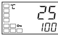
PV/SP
Protect Level
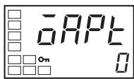
Operation/Adjustment Protect
Protect Level
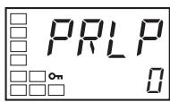
Password to Move to Protect Level
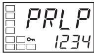
- Press the and Keys simultaneously for at least the time set in the Move to Protect Level Time parameter to move from the operation level to the protect level.
-
Select the Password to Move to Protect Level parameter by pressing the Key.
-
Press the and Keys to set the parameter to 1234. (To prevent setting the password incorrectly, the and Keys or and Keys must be pressed simultaneously to set the password.)
Note Protection cannot be cleared or changed without the password. Be careful not to forget it. If you forget the password, contact your OMRON sales representative.
Communications Operation Command to Move to the Protect Level
Note
- The Write Variable operation command can be used via communications to write the password to the Move to Protect Level parameter. When the correct password is written, the display will change to the Operation/Adjustment Protect parameter and writing the parameters in the protect level will be enabled.
(1) If the Write Variable operation command is used to write the wrong password to the Move to Protect Level parameter after the correct parameter has been written, the Move to Protect Level parameter will be displayed and any Write Variable operation commands to write parameters in the protect level will result in operation errors.
(2) If a password is not set or if it is set to 0, the display will change to the Operation/Adjustment Protect parameter and writing the parameters in the protect level will be enabled immediately.
4-10 PV Change Color
4-10-1 PV Color Change Function
Use the PV color change function to change the color of the PV display (No. 1 display).
There are three display colors, orange, red, and green, and you can select from the following three modes and eight functions.
PV Change Color
- Constant: This mode displays orange, red, or green all the time.
- Linked to Alarm 1: This mode switches the PV display color from red to green when alarm 1 turns ON or from green to red when alarm 1 turns ON.
- Linked to PV stable band: This mode switches the PV display color between red outside the PV stable band and green within PV stable band, or between green outside the PV stable band and red within PV stable band.
Set the PV stable band in the PV Stable Band parameter (advanced function setting level).
The default is R (red).
The following tables show the display functions that can be set using the PV color change function.
| Mode | Setting | Function | PV change color | Application example | ||
| Constant | aRb | Orange | Constant: Orange | To match the display color with other Controller models | ||
| Red | Red | Constant: Red | To match the display color with other Controller models | |||
| GRN | Green | Constant: Green | To match the display color with other Controller models | |||
| Linked to alarm 1 | Alarm value ALM1 lit PV SP | |||||
| ALM1 not lit | ALM1 lit | Application example | ||||
| R-G | Red to Green | Red | Green | To display the PV reached signal | ||
| G-R | Green to Red | Green | Red | To display error signals | ||
| Linked to PV stable band | PV stable band Low Within High PV SP | |||||
| Low | Within PV stable band | High | Application example | |||
| R-G,R | Red to Green to Red | Red | Green | Red | To display stable status | |
| G-G,R | Green to Orange to Red | Green | Orange | Red | To display stable status | |
| G-G,R | Orange to Green to Red | Orange | Green | Red | To display stable status | |
PV Stable Band
PV Stable Band
When the mode to link to the PV stable band is selected, the PV display color will change according to whether the present value (PV) is lower than, within, or higher than the PV stable band shown in the following figure. The PV stable band is set with the SP as the center, as shown below.
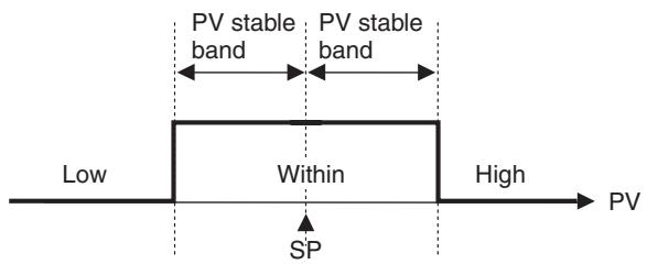
The default is 5.0(^ / ^) for Controllers with Thermocouple/Resistance Thermometer Universal Inputs and 5.00% FS for Controllers with Analog Inputs.
4-10-2 Setting
Setting the PV Change Color to Indicate Stable Status
To display the PV in a stable green display when the PV is within ± 15.0^ of the set point to enable checking the control process at a glance, set the PV Change Color and PV Stable Band parameters.
PV change color = R - R (Red to Green to Red)
PV stable band = 15.0^
Operating Procedure
Release the protection before setting the PV Change Color and PV Stable Band parameters to enable moving to advanced function setting level. (Refer to steps 1 to 8 on page 108.)
Operation Level
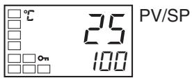
Initial Setting Level
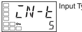
Initial Setting Level
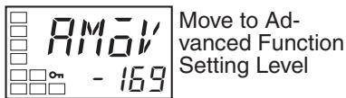
Advanced Function Setting Level
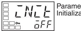
Advanced Function Setting Level
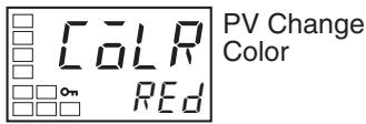
- Press the Key for at least three seconds to move from the operation level to the initial setting level.
- Select the Move to Advanced Function Setting Level parameter by pressing the 回 Key.
- Use the Key to enter “-169” (the password).
Move to the advanced function setting level by pressing the 回 Key or leaving the setting for at least two seconds.
- Select the PV Change Color parameter by pressing the Key.
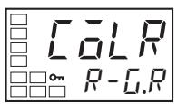
Advanced Function Setting Level
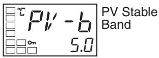
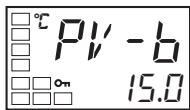
Operation Level
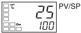
- Press the Key to set the parameter to R - R .
-
Select the PV Stable Band parameter by pressing the 一 Key.
-
Use the Key to set the parameter to 15.0.
- To return to the initial setting level, press the Key for at least one second.
- To return to the operation level, press the Key for at least one second.
4-11 Alarm Delays
4-11-1 Alarm Delays
- Delays can be set for the alarm outputs. ON and OFF delays can be set separately for alarms 1, 2, and 3. The ON and OFF delays for alarm 1 function only for the alarm function. If the alarm 1 function is set to be output as an OR with other alarms (i.e., the heater burnout alarm, HS alarm, heater overcurrent alarm, or input error output alarm), delays cannot be set for the other alarms. The ON and OFF delays for alarms 1, 2, and 3 also apply to the individual SUB1, SUB2, and SUB3 indicators and to communications status. The alarm ON delays will also function when power is turned ON or when moving from the initial setting level to operation level (e.g., to software resets). All outputs will turn OFF and the OFF delays will not function when moving to the initial setting level or when an alarm is output for a A/D converter error.
Operation of Alarm ON and OFF Delays (for an Upper-limit Alarm)
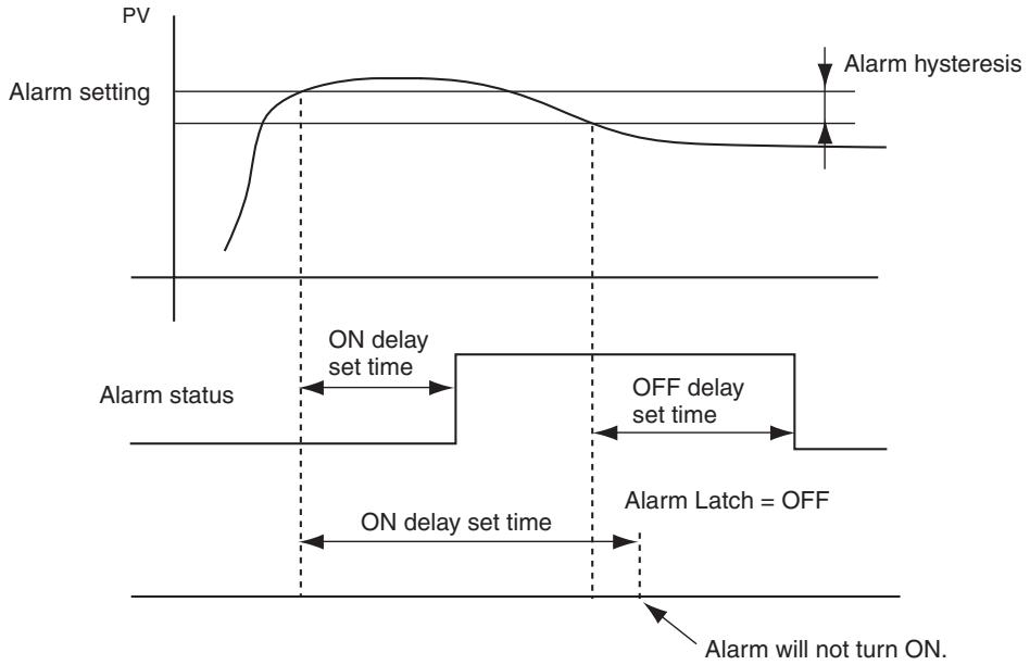
- The alarm will not turn ON if the time that the alarm is ON is equal to or less than the ON delay set time. Also, the alarm will not turn OFF if the time that the alarm is OFF is equal to or less than the OFF delay set time.
- If an alarm turns OFF and then back ON during the ON delay time, the time will be remeasured from the last time the alarm turns ON. Also, if an alarm turns ON and then back OFF during the OFF delay time, the time will be remeasured from the last time the alarm turns OFF.
Parameters Related to Alarm Delays
| Parameter name | Symbol | Set (monitor) values |
| Alarm 1 ON Delay | R10N | 0 to 999 (s) |
| Alarm 2 ON Delay | R20N | 0 to 999 (s) |
| Alarm 3 ON Delay | R30N | 0 to 999 (s) |
| Alarm 1 OFF Delay | R10F | 0 to 999 (s) |
| Alarm 2 OFF Delay | R20F | 0 to 999 (s) |
| Alarm 3 OFF Delay | R30F | 0 to 999 (s) |
Note
(1) The defaults are 0, i.e., the ON and OFF delays are disabled.
(2) The parameters are displayed when alarm functions are assigned and when the alarm type is set to any type but 0 (none), 12: LBA, or 13: PV change rate alarm.
Operating Procedure
Use the following procedure to set ON and OFF delays for the alarm 1.
An ON delay of 5 seconds and an OFF delay of 10 s will be set.
Operation Level
Initial Setting Level
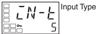
Initial Setting Level
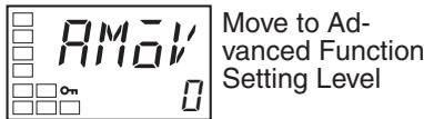
Advanced Function Setting Level
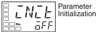
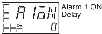
Advanced Function Setting Level
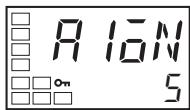
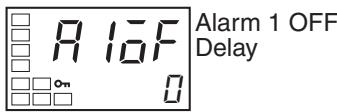
Advanced Function Setting Level
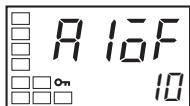
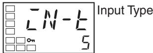
Initial Setting Level
- Press the Key for at least three seconds to move from the operation level to the initial setting level.
- Select the Move to Advanced Function Setting Level parameter by pressing the Key. (For details on moving between levels, refer to 4-8 Moving to the Advanced Function Setting Level.)
- Press the Key to enter the password (-169) and move from the initial setting level to the advanced function setting level.
- Press the Key to select the Alarm 1 ON Delay parameter.
- Press the Key to set the parameter to 5.
- Press the Key to select the Alarm 1 OFF Delay parameter.
- Press the Key to set the parameter to 10.
- Press the Key for at least one second to move from the advanced function setting level to the initial setting level.
Operation Level
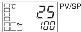
- Press the Key for at least one second to move from the initial setting level to the operation level.
4-12 Loop Burnout Alarm
4-12-1 Loop Burnout Alarm (LBA)
- With a loop burnout alarm, there is assumed to be an error in the control loop if the control deviation (SP - PV) is greater than the threshold set in the LBA Level parameter and if the control deviation is not reduced by at least the value set in the LBA Detection Band parameter within the LBA detection time.
- Loop burnout alarms are detected at the following times.
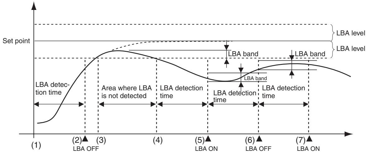
If the control deviation is reduced in the area between 1 and 2 (i.e., the set point is approached) and the amount the control deviation is reduced is at least equal to the LBA band, the loop burnout alarm will remain OFF.
The process value is within the LBA level between 3 and 4, and thus loop burnout alarms will not be detected. (The loop burnout alarm will remain OFF.)
If the process value is outside the LBA level between 4 and 5 and the control deviation is not reduced by at least the LBA band within the LBA detection time, the loop burnout alarm will turn ON.
If the control deviation is reduced in the area between 5 and 6 (i.e., the set point is approached) and the amount the control deviation is reduced is at least equal to the LBA band, the loop burnout alarm will turn OFF.
If the control deviation is reduced in the area between 6 and 7 (i.e., the set point is approached) and the amount the control deviation is reduced is less than the LBA band, the loop burnout alarm will turn ON.
- If the LBA detection time, LBA level, LBA detection band, and PID settings are not appropriate, alarms may be detected inappropriately or alarms may not be output when necessary.
- Loop burnout alarms may be detected if unexpectedly large disturbances occur continuously and a large deviation does not decrease.
-
If a loop burnout occurs when the set point is near the ambient temperature, the temperature deviation in a steady state may be less than the LBA level, preventing detection of the loop burnout.
-
If the set point is so high or low that it cannot be reached even with a saturated manipulated variable, a temperature deviation may remain even in a steady state and a loop burnout may be detected.
- Detection is not possible if a fault occurs that causes an increase in temperature while control is being applied to increase the temperature (e.g., an SSR short-circuit fault).
- Detection is not possible if a fault occurs that causes a decrease in temperature while control is being applied to decrease the temperature (e.g., a heater burnout fault).
Parameters Related to Loop Burnout Alarms
| Parameter name | Symbol | Setting range | Remarks | |
| LBA Detection Time | LbR | 0 to 9999 (s) | Setting 0 disables the LBA function. | |
| LBA Level | LbRL | Controllers with Thermo-couple/Resistance Thermometer Universal Inputs | 0.1 to 999.9 (°C/°F) (See note.) | Default: 8.0 (°C/°F) |
| Controllers with Analog Inputs | 0.01 to 99.99 (%FS) | Default: 10.00% FS | ||
| LBA Band | LbRb | Controllers with Thermo-couple/Resistance Thermometer Universal Inputs | 0.0 to 999.9 (°C/°F) (See note.) | Default: 3.0 (°C/°F) |
| Controllers with Analog Inputs | 0.00 to 99.99 (%FS) | Default: 0.20% FS | ||
Note Set "None" as the unit for analog inputs.
- A loop burnout alarm can be output by setting the alarm 1 type to 12 (LBA).
- A setting of 12 (LBA) can be set for alarm 2 or alarm 3, but the setting will be disabled.
- Loop burnouts are not detected during SP ramp operation.
- Loop burnouts are not detected during auto-tuning, manual operation, or while stopped.
- If the alarm 1 latch is set to ON, the latch will be effective for the loop burnout alarm.
Automatically Setting the LBA Detection Time
- The LBA detection time is automatically set by auto-tuning. (It is not set automatically, however, for heating/cooling control.)
- If the optimum LBA detection time is not obtained by auto-tuning, set the LBA Detection Time parameter (advanced function setting level).
Determining the LBA Detection Time
1,2,3...
-
To manually set the LBA detection time, set the LBA Detection Time parameter to twice the LBA reference time given below.
-
Set the output to the maximum value.
- Measure the time required for the width of change in the input to reach the LBA band.
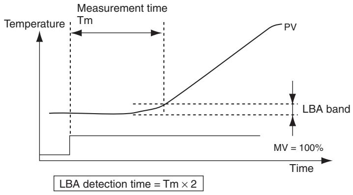
- Set the LBA Detection Time parameter to two times the measured time.
LBA Level
- Set the control deviation when the control loop is working properly.
- The default is 8.0(^ C / ^ F) for Controllers with Thermocouple/Resistance Thermometer Universal Inputs and 10.00 % FS for Controllers with Analog Inputs.
LBA Band
- There is assumed to be an error in the control loop if the control deviation is greater than the threshold set in the LBA Level parameter and if the control deviation does not change by at least the value set in the LBA Band parameter.
- The default is 3.0(^ / ^) for Controllers with Thermocouple/Resistance Thermometer Universal Inputs and 0.20% FS for Controllers with Analog Inputs.
Operating Procedure
Perform the following procedure to use the loop burnout alarm.
In this example, the LBA detection time is set to 10, the LBA level is set to 8.0, and the LBA band is set to 3.0.
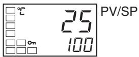
Operation Level
Initial Setting Level
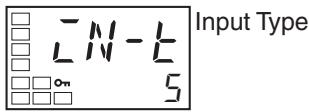
Initial Setting Level
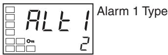
- Press the Key for at least three seconds to move from the operation level to the initial setting level.
- Select the Alarm 1 Type parameter by pressing the Key.
Initial Setting Level
Move to Advanced Function Setting Level
Advanced Function Setting Level
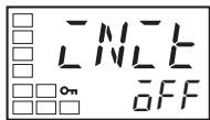
Parameter Initialization
Advanced Function Setting Level
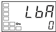
LBA Detection Time
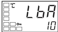
Advanced Function Setting Level
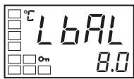
LBA Level
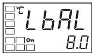
Advanced Function Setting Level
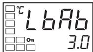
LBA Band
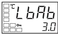
Initial Setting Level
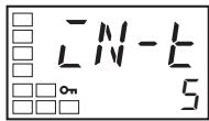
Input Type
Operation Level

PV/SP
- Press the Key to set the parameter to 12.
- Select the Move to Advanced Function Setting Level parameter by pressing the . (For details on moving between levels, refer to 4-8 Moving to the Advanced Function Setting Level.)
- Press the Key to enter the password (-169), and move from the initial setting level to the advanced function setting level.
- Select the LBA Detection Time parameter by pressing the 一 Key.
- Press the Key to set the parameter to 10.
- Select the LBA Level parameter by pressing the Key.
- Press the Key to set the parameter to 8.0. (The default is 8.0.)
-
Select the LBA Band parameter by pressing the Key.
-
Press the or Key to set the parameter to 3.0. (The default is 3.0.)
- Press the Key for at least one second to move from the advanced function setting level to the initial setting level.
- Press the Key for at least one second to move from the initial setting level to the operation level.
4-13 Performing Manual Control
4-13-1 Manual Operation
- The manipulated variable can be set in manual mode if the PV/MV parameter is displayed in the manual control level. The final MV used in automatic mode will be used as the initial manual MV when moving from automatic mode to manual mode. In manual mode, the change value will be saved immediately and reflected in the actual MV.
- The automatic display return function will not operate in manual mode.
- Balanceless-bumpless operation will be performed for the MV when switching from manual operation to automatic operation. (See note.)
- If a power interruption occurs during manual operation, manual operation will be restarted when power is restored using the same MV as when power was interrupted.
- Switching between automatic and manual operation is possible for a maximum of one million times.
- Manual operation can be used only for PID control.
Note
In balanceless-bumpless operation, the MV before switching is used initially after the switch and then gradually changed to achieve the proper value after switch to prevent radical changes in the MV after switching operation.
The overall manual operation is illustrated in the following figure.
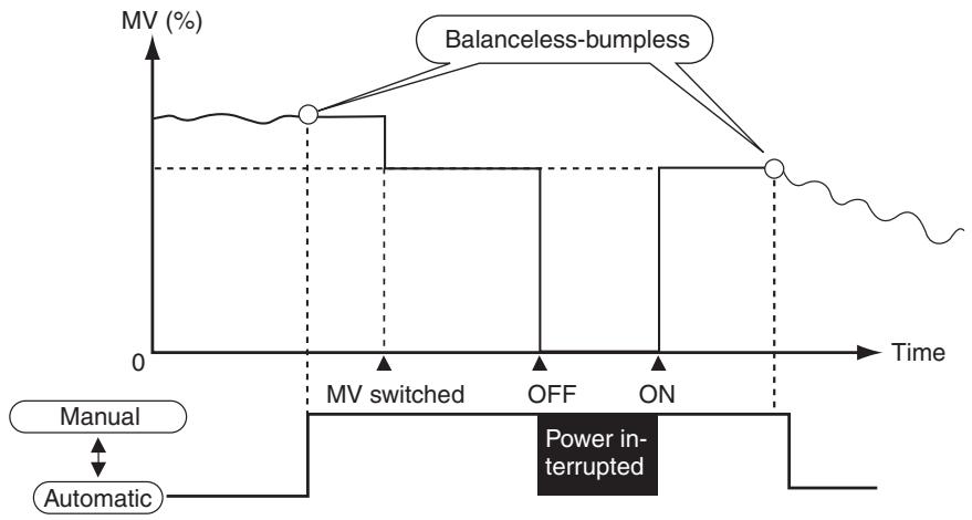
Related Displays and Parameters
| Parameter name | Symbol | Level | Remarks |
| PV/MV (Manual MV) | --- | Manual Control Level | -5.0 to 105.0 (heating/cooling control: -105.0 to 105.0 (See note 2.) |
| Auto/Manual Switch | R-M | Operation Level | Switches between automatic and manual modes. |
| Auto/Manual Select Addition | RMRed | Advanced Function Setting Level | Enables switching between automatic and man-ual modes. |
Note
(1) Refer to 4-16 Output Adjustment Functions for information on the priority for the MV.
(2) For Manual MV Limit Enable, this value will be between the MV upper limit and the MV lower limit.
Manual MV Limit Enable
When the Manual MV Limit Enable parameter is set to ON (enabled), the MV limits will function and the setting range for the Manual MV parameter will be between the MV upper limit and the MV lower limit. When the parameter is set to OFF (disabled), MV limits will not function.
Moving from the Operation Level to the Manual Control Level
| Parameter name | Setting range | Default |
| Manual MV Limit Enable | OFF: Disabled, ON: Enabled | ON |
- When the Key is pressed for at least 3 seconds in the operation level's auto/manual switching display, the manual mode will be entered and the manual control level will be displayed. It is not possible to move to any displays except for the PV/MV parameter during manual operation. Press the Key for at least one second from the PV/MV parameter display in manual control level to return to automatic mode and display the top parameter in the operation level.
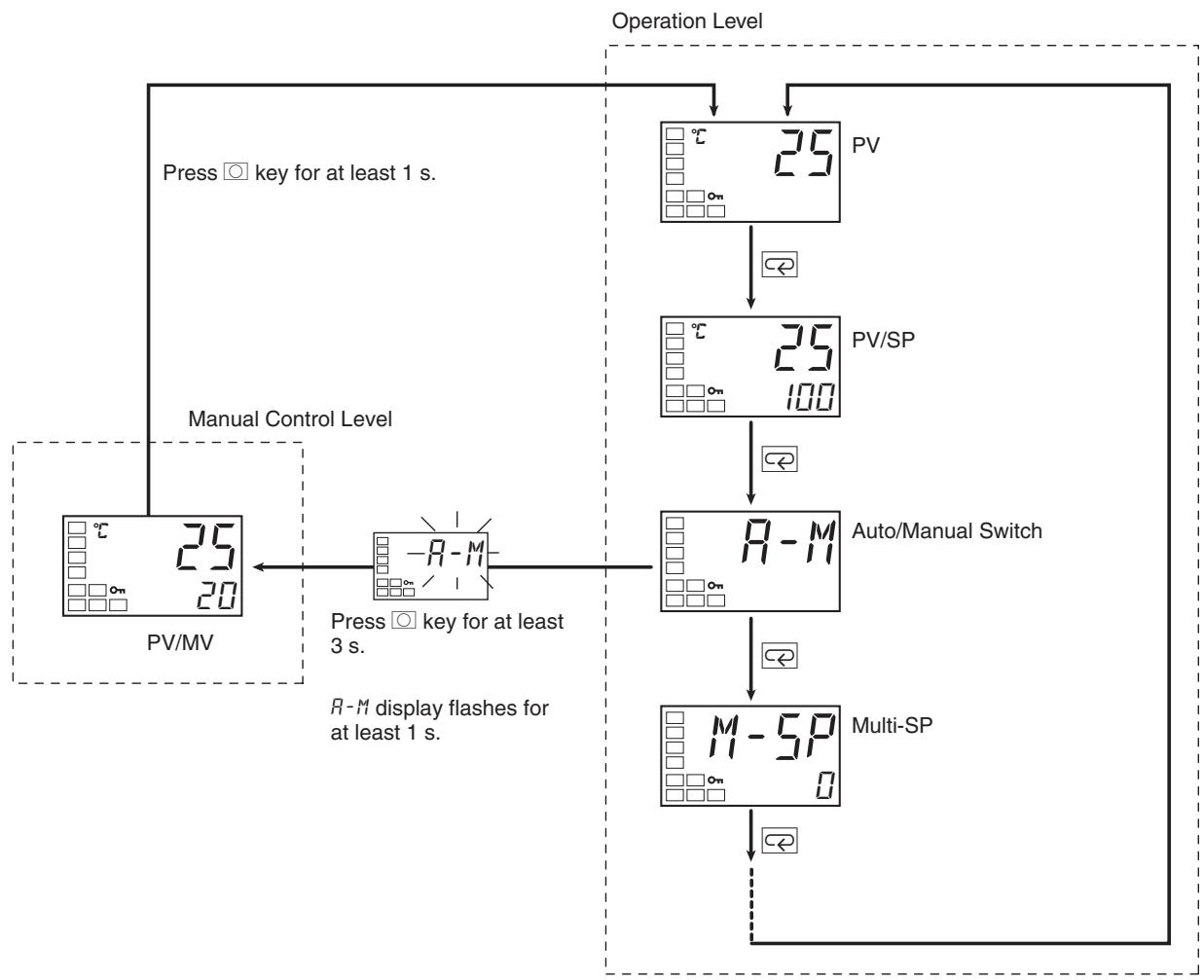
- If an event input is set to MANU (auto/manual), the Auto/Manual Switch parameter will not be displayed. Use the event input to switch between automatic and manual modes.
Using the PF Key to Move to the Manual Control Level
- When the PF Setting parameter is set to A-M (Auto/Manual), pressing the PF Key for at least one second while in the adjustment or operation level will change the mode to manual mode and move to the manual control level. During manual operation it is not possible to move to any displays other than PV/MV (Manual MV). Press the PF Key for at least one second from the PV/MV display in the manual control mode to change the mode to automatic mode, move to the operation level, and display the top parameter in the operation level.
- When MANU (Auto/Manual) is selected for an event input, the Auto/Manual Switch parameter is not displayed. In that case, switching between auto and manual mode is executed by using an event input.
Auto/Manual Select Addition
- The Auto/Manual Select Addition parameter must be set to ON in the advanced function setting level before it is possible to move to manual mode. The default is OFF.
Note
(1) Priority of Manual MV and Other Functions
Even when operation is stopped, the manual MV is given priority.
Auto-tuning and self-tuning will stop when manual mode is entered.
(2) Manual MV and SP Ramp
If operating, the SP ramp function will continue even when manual mode is entered.
Operating Procedure
Use the following procedure to set the manipulated variable in manual mode.
Operation Level
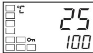
PV/SP
Initial Setting Level
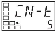
Input Type
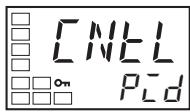
Initial Setting Level
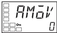
Move to Advanced Function Setting Level
Advanced Function Setting Level
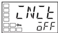
Parameter Initialization
Advanced Function Setting Level
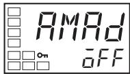
Auto/Manual Select Addition
- Press the Key for at least three seconds to move from the operation level to the initial setting level.
- Press the to select PID-ON/OFF and then select PID with the .
- Select the Move to Advanced Function Setting Level parameter by pressing the Key. (For details on moving between levels, refer to 4-8 Moving to the Advanced Function Setting Level.)
- Press the to enter the password (-169), and move from the initial setting level to the advanced function setting level.
- Select the Auto/Manual Select Addition parameter by pressing the Key.
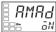
Initial Setting Level
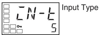
Operation Level
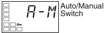
Manual Control Level
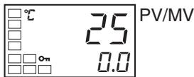
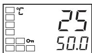
Operation Level
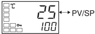
Operating Procedure
Operation Level
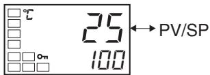
Initial Setting Level
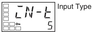
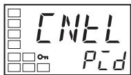
Initial Setting Level
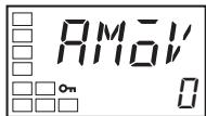
Move to Advanced Function Setting Level
- Use the Key to set the parameter to ON.
- Press the Key for at least one second to move from the advanced function setting level to the initial setting level.
- Press the Key for at least one second to move from the initial setting level to the operation level.
- Select the Auto/Manual Switch parameter by pressing the 一 Key.
- Press the Key for at least three seconds to move from the operation level to the manual control level.
- Press the or Key to set the manual MV. (In this example, the MV is set to 50.0% .)
Note The manual MV setting must be saved (see page 18), but values changed with Key operations are reflected in the control output immediately.
- Press the Key for at least one second to move from the manual control level to the operation level.
In this example, A-M (Auto/Manual) is set for the PF Setting parameter (E5AN/EN only).
- Press the Key for at least three seconds to move from the operation level to the initial setting level.
- Press the to select PID-ON/OFF and then select PID with the .
- Select the Move to Advanced Function Setting Level parameter by pressing the Key. (For details on moving between levels, refer to 4-8 Moving to the Advanced Function Setting Level.)
Advanced Function Setting Level
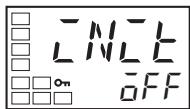
Parameter Initialization
Advanced Function Setting Level
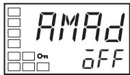
Auto/Manual Select Addition
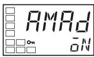
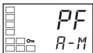
Initial Setting Level
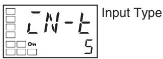
Manual Control Level

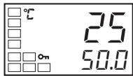
Operation Level
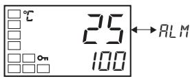
- Press the × Key to enter the password (-169), and move from the initial setting level to the advanced function setting level.
- Select the Auto/Manual Select Addition parameter by pressing the 一 Key.
- Use the Key to set the parameter to ON.
- Press the Key to select the PF Setting parameter and confirm that it is set to "A-M." ("A-M" is the default setting.)
- Press the Key for at least one second to move from the advanced function setting level to the initial setting level.
- Press the Key for at least one second to move from the initial setting level to the operation level.
- Press the PF Key for at least one second to move from the operation level to the manual control level.
- Press the or Key to set the manual MV. (In this example, the MV is set to 50.0% .)
Note The manual MV setting must be saved (see page 18), but values changed with key operations are reflected in the control output immediately. - Press the PF Key to move from the manual control level to the operation level.
4-14 Using the Transfer Output
4-14-1 Transfer Output Function
-
To use a transfer output, change the setting for the Transfer Type parameter to anything other than OFF. (This will enable the Transfer Output Upper Limit and Transfer Output Lower Limit parameters.)
-
The operation is shown in the following table.
| Control output 1 | Control output 2 | Transfer output destination |
| Current output | None, relay output, voltage output (for driving SSR) | Control output 1 |
| Relay output, voltage output (for driving SSR) | None, relay output, voltage output (for driving SSR) | None |
■ Precision and User Calibration
| Precision | User calibration | |
| Simple transfer out-put | Not specified. | Not supported. |
Transfer Output Type
| Transfer output type | Symbol | Setting range |
| OFF (See note 1.) | \(\overline{a}FF\) | --- |
| Set point | \(5P\) | SP lower limit to SP upper limit |
| Set point during SP ramp | \(5P-M\) | SP lower limit to SP upper limit |
| PV | \(PV\) | Input setting range lower limit to input setting range upper limit or Scaling lower limit to scaling upper limit |
| MV monitor (heating) | \(MV\) | -5.0 to 105.0 (heating/cooling control: 0.0 to 105.0) (See note 2.) |
| MV monitor (cooling) | \(\overline{C-MV}\) | 0.0 to 105.0 (See note 2.) |
Note
(1) The default is OFF.
(2) The output value will be different between when the Transfer Output Type parameter is set to a heating control output or cooling control output, and when the Control Output 1 Assignment parameter is set to a heating control output or cooling control output.
Example: When a Current Output Is Set to 4 to 20mA and MV Monitor (Heating) Is Selected
When used as a transfer output, 4.0mA will be output for 0% and 20.0mA will be output for 100% .
When used as a control output, 3.7mA will be output for 0% and 20.3mA will be output for 100% so that the actuator is controlled at 0% or 100% .
Output current (mA)
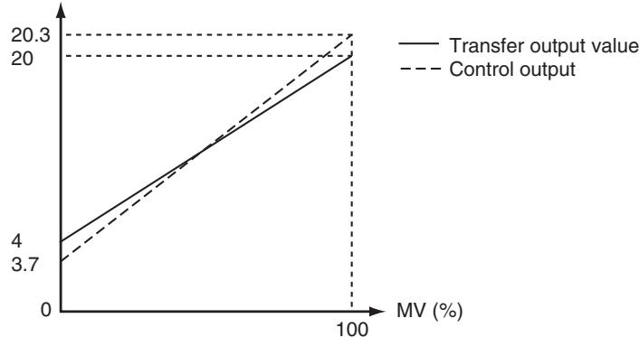
(The above graph is for when the linear current output type is set to 4 to 20mA .)
Transfer Scaling
- Reverse scaling is possible by setting the Transfer Output Lower Limit parameter larger than the Transfer Output Upper Limit parameter. If the Transfer Output Lower Limit and Transfer Output Upper Limit parameters are set to the same value when 4 to 20mA is set, the transfer output will be output continuously at 0% (4 mA).
- If the SP, SP during SP ramp, or PV is selected, the Transfer Output Lower Limit and Transfer Output Upper Limit parameters will be forcibly initialized to the respective upper and lower setting limits for changes in the upper and lower limits of the SP limiter and the temperature unit. If the MV for heating or MV for cooling is selected, the Transfer Output Lower Limit and Transfer Output Upper Limit parameters will be initialized to 100.0 and 0.0, respectively, when a switch is made between standard control and heating/cooling control using the Standard or Heating/Cooling parameter.
- The output current when the linear current type is set to 4 to 20mA , the transfer output upper limit is set to 90.0, and the transfer output lower limit is set to 10.0 is shown in the following graph.
- For scaling from 0.0% to 100.0% , the output for -5.0 to 0.0 will be the same value as for 0.0% , and the output for 100.0 to 105.0 will be the same value as for 100.0% .
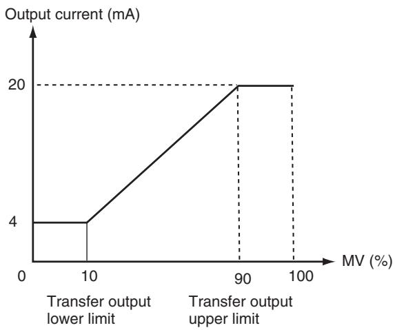
(The above graph is for when the linear current output type is set to 4 to 20mA .)
Operating Procedure
The following procedure sets the transfer output for an SP range of -50 to 200.
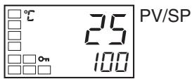
Operation Level
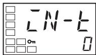
Initial Setting Level
Input Type
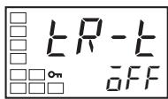
Initial Setting Level
Transfer Output Type
- Press the Key for at least three seconds to move from the operation level to the initial setting level.
- Select the Transfer Output Type parameter by pressing the Key.
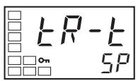
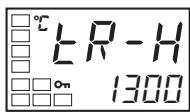
Initial Setting Level
Transfer Output Upper Limit
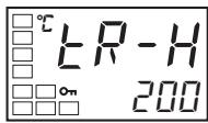

Initial Setting Level
Transfer Output Lower Limit
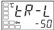
Operation Level
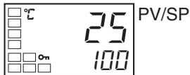
- Press the Key to select 5^P (set point).
-
Select the Transfer Output Upper Limit parameter by pressing the 一 Key.
-
Use the 量 Key to set the parameter to 200. The default is 1300.
- Select the Transfer Output Lower Limit parameter by pressing the 一 Key.
- Use the Key to set the parameter to -50. The default is -200.
- To return to the operation level, press the Key for at least one second.
4-15 Using the Simple Program Function
4-15-1 Simple Program Function
- The simple program function can be used for the following type of control.
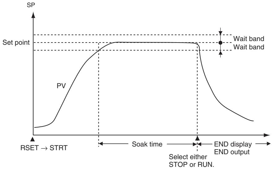
- The program will start when the Program Start parameter is changed from RSET to STRT. END will be displayed on the No. 2 display and the output assigned as the program end output will turn ON after the time set in the Soak Time parameter has expired in the wait band. The Program Pattern parameter can be used to select moving to STOP mode or continuing operation in RUN mode after the program ends.
Parameters Related to the Simple Program Function
| Parameter name | Symbol | Set (monitor) values | Unit | Display level |
| Program Pattern | PERN | OFF, STOP, CONT | --- | Initial setting level |
| Program Start | PRSET | RSET, STRT | --- | Operation level |
| Soak Time | S0AHK | 1 to 9999 | min or h | Adjustment level |
| Soak Time Unit | t - U | m (minutes)/h (hours) | --- | Advanced function setting level |
| Wait Band | Wt - b | OFF or 0.1 to 999.9 (See note 2.) | °C or °F (See notes 1 and 2.) | Adjustment level |
| Soak Time Remain Monitor | SkerR | 0 to 9999 | min or h | Operation level |
Note
(1) Set for Controllers with Thermocouple/Resistance Thermometer Universal Inputs. Set "None" as the unit for Controllers with Analog Inputs.
(2) The setting unit of the Wait Band parameter is %FS for Controllers with Analog Inputs and the setting range is OFF or 0.01 to 99.99.
Program Pattern
Either of two program patterns can be selected. The simple program operation will not be performed if the Program Pattern parameter is set to OFF.
■ Pattern 1 (STOP)
Control will stop and the STOP mode will be entered when the program has ended.
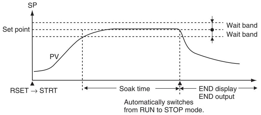
Pattern 2(CONT)
Control will continue in RUN mode when the program has ended.
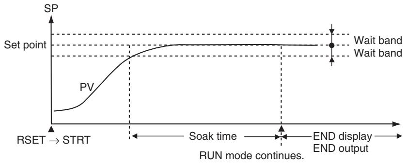
Starting Method
Any of the following three methods can be used to start the simple program.
- Setting the Program Start parameter to STRT.
- Turning ON an event input. (The program start must be assigned to an event input. See note.)
- Starting with an Operation Command using communications. (When the program start is not assigned to an event input.)
Note
When the simple program is started and reset, writing is performed to EEPROM. Be sure to consider the write life (1 million writes) of the EEPROM in the system design. When the program start is assigned to an event input, the Program Start parameter will function as a monitor display, and the RSET/STRT displays can be used to check when the event input has started or reset the simple program. When this is done, the Program Start parameter functions as a monitor display only and cannot be changed using key operations. If the Program Pattern parameter is set to OFF, the event input assignment setting will be initialized to "None."
Soak Time and Wait Band
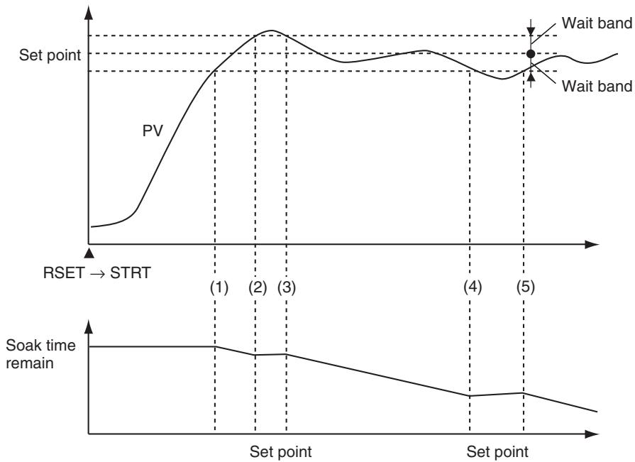
The wait band is the band within which the process value is stable in respect to the set point. The soak time is measured within the wait band. The timer that measures the soak time operates only when the process value is within the wait band around the set point (i.e., SP ± wait band). In the following diagram, the timer will be stopped between the start and (1), (2) and (3), and (4) and (5) and will measure the time only between (1) and (2), (3) and (4), and (5) and the end.
Note
If the wait band is set to OFF, the wait band will be treated as infinity and the timer will measure time continuously after changing from RSET to STRT.
4-15-2 Operation at the Program End
Display at the Program End
When the program ends, the process value will be displayed on the No. 1 display (see note) and the set point and "end" will be alternately displayed on the No. 2 display at 0.5 s intervals.
Note One of the following displays: PV/SP, PV only, or PV/MV.
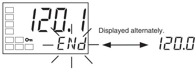
Program End Output
The output assignment parameters can be used to assign the program END output to any output. The program END output can also be used in communications status.
E5CN/CN-U, E5AN/EN
When the Program Pattern parameter is changed from OFF to STOP or CONT for the E5CN, E5CN-U, E5AN, or E5EN, the Auxiliary Output 1 Assignment parameter will automatically be set to the END output. When the Program Pattern parameter is changed from STOP or CONT to OFF, the Alarm 1 Output Assignment parameter will automatically be initialized to ALM1.
E5GN
When the Program Pattern parameter is changed from OFF to STOP or CONT for the E5GN, the Auxiliary Output 1 Assignment parameter will automatically be set to the END output. When the Program Pattern parameter is changed from STOP or CONT to OFF, the Alarm 1 Output Assignment parameter will automatically be initialized to ALM1. When using heating/cooling control and the Program Pattern parameter is changed from OFF to STOP or CONT, the END output will not be assigned to an output. Use the output assignment parameters to assign the program END output to the desired output.
Clearing the Program End Status
The program END output and display will be cleared when the Program Start parameter is changed from STRT to RSET. The setting is changed from STRT to RSET while the Program Start parameter is displayed.
The program END status can also be cleared using an event. If the program start function is assigned to an event, however, the program end status cannot be cleared from the Program Start parameter display, which will function only as a monitor display.
Operating Procedure
Perform the following procedure to use the simple program function.
In this example, the program pattern will be set to STOP, the soak time to 10 min, and the wait band to 3.
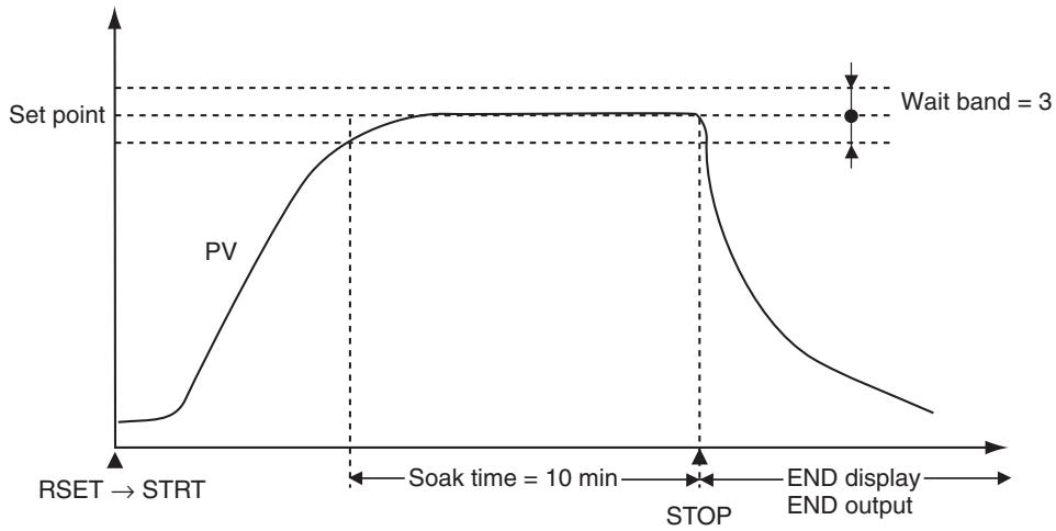
Operation Level
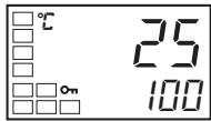
PV/SP
Initial Setting Level
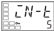
Input Type
Initial Setting Level
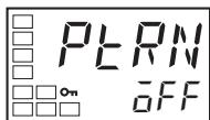
Program Pattern
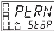
Operation Level
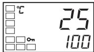
PV/SP
Adjustment Level
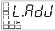
Adjustment Level Display
Adjustment Level

Soak Time
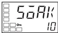
- Press the Key for at least three seconds to move from the operation level to the initial setting level.
- Select the Program Pattern parameter by pressing the Key.
- Use the Key to set the parameter to STOP.
- Press the Key for at least one second to move from the initial setting level to the operation level.
- Press the Key to move from the operation level to the adjustment level.
- Select the Soak Time parameter by pressing the Key.
- Use the to set the parameter to 10. (The soak time unit is set in Soak Time Unit parameter in the advanced function setting level. The default is M (minutes).
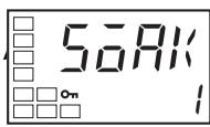
Soak Time
- Select the Soak Time parameter by pressing the 一 Key.
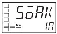
- Use the Key to set the parameter to 10. (The soak time unit is set in Soak Time Unit parameter in the advanced function setting level. The default is M (minutes).
4-15-3 Application Example Using a Simple Program
The program will be started by changing the setting of the Program Start parameter. The following example shows using a simple program with the program pattern set to STOP.
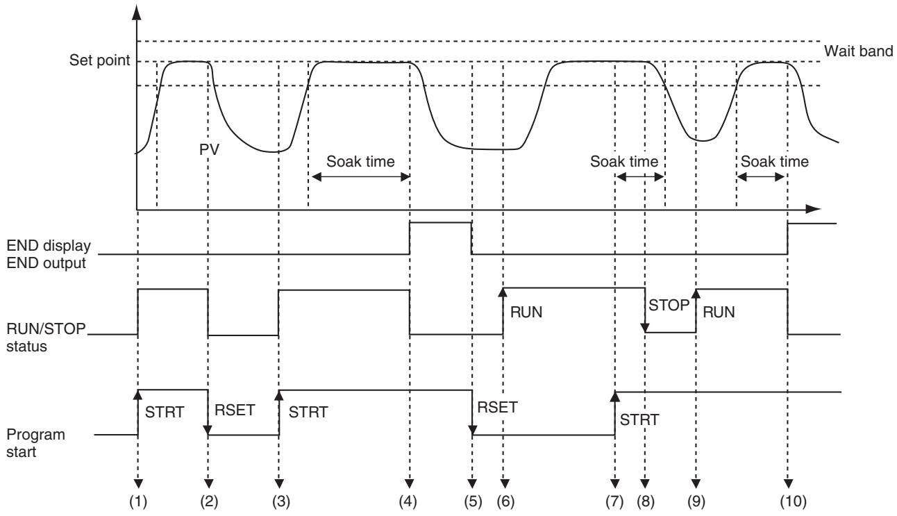
| Timing | Description |
| (1) | The Program Start parameter was changed from RSET to STRT using either an event or key operations. The RUN/STOP status automatically changes to RUN mode when the above operation is performed. |
| (2) | The Program Start parameter was changed from STRT to RSET using either an event or key operations before the soak time expired. The RUN/STOP status automatically changes to STOP mode when the above operation is performed. |
| (3) | The Program Start parameter is again changed from RSET to STRT using either an event or key operations. The RUN/STOP status will automatically change to RUN mode when the above operation is performed. |
| (4) | The RUN/STOP status automatically changes to STOP mode when soak time expires. END flashes on the No. 2 display and the program END output turns ON. |
| (5) | The Program Start parameter is changed from STRT to RSET using either an event or key operations. The END display is cleared and the program END output turns OFF. |
| (6) | Key operations are used to switch the RUN/STOP status to RUN with the Program Start parameter set to RSET (stopped). Normal control operation is started. |
| (7) | The Program Start parameter is changed from RSET to STRT after the process value stabilizes. The RUN/STOP status remains as RUN. |
| (8) | Key operations are used to change the RUN/STOP status to STOP (during program operation). Measuring the soak time is continued within the wait band. (Measuring the soak time stops when the process value leaves the wait band.) |
| (9) | Key operations are used to change the RUN/STOP status to RUN. Measuring the soak time is continued within the wait band (continuing from the time between (7) and (9)). |
| (10) | The RUN/STOP status automatically changes to STOP mode when the measured time reaches the soak time. END flashes on the No. 2 display and the program END output turns ON. |
4-16 Output Adjustment Functions
4-16-1 Output Limits
- Output limits can be set to control the output using the upper and lower limits to the calculated MV.
- The following MV takes priority over the MV limits. Manual MV (See note.)
MV at stop
MV at PV error
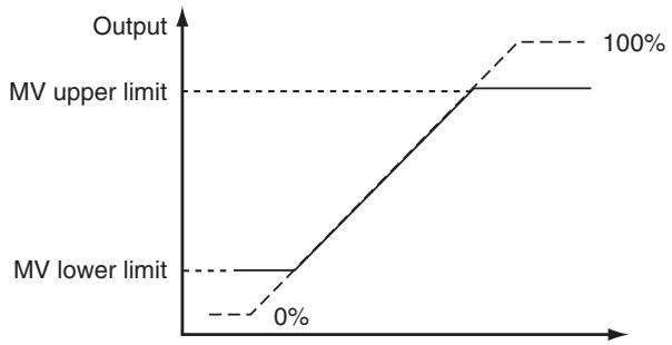
Note When the manual MV limit is enabled, the manual MV will be restricted by the MV limit.
- For heating/cooling control, upper and lower limits are set of overall heating/cooling control. (They cannot be set separately for heating/cooling.)
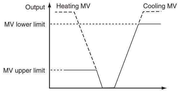
4-16-2 MV at Stop
- The MV when control is stopped can be set.
For heating/cooling control, the MV at stop will apply to the cooling side if the MV is negative and to the heating side if the MV is positive. When setting the MV when control is stopped, set the MV at Stop and Error Addition parameter (advanced function setting level) to ON. The default is 0.0, so an MV will not be output for either standard or heating/cooling control.
| Parameter name | Setting range | Unit | Default |
| MV at STOP | -5.0 to 105.0 for standard control | % | 0.00 |
| -105.0 to 105.0 (heating/cooling control) |
Note The order of priority is as follows: Manual MV > MV at stop > MV at PV error.
4-16-3 MV at PV Error
- The MV to be output for input errors can be set.
The MV at stop takes priority when stopped and the manual MV takes priority in manual mode.
| Parameter name | Setting range | Unit | Default |
| MV at PV ERROR | -5.0 to 105.0 for standard control | % | 0.0 |
| -105.0 to 105.0 (heating/cooling control) |
Note The order of priority is as follows: Manual MV > MV at stop > MV at PV error.
- The order of priority of the MVs is illustrated in the following diagram.
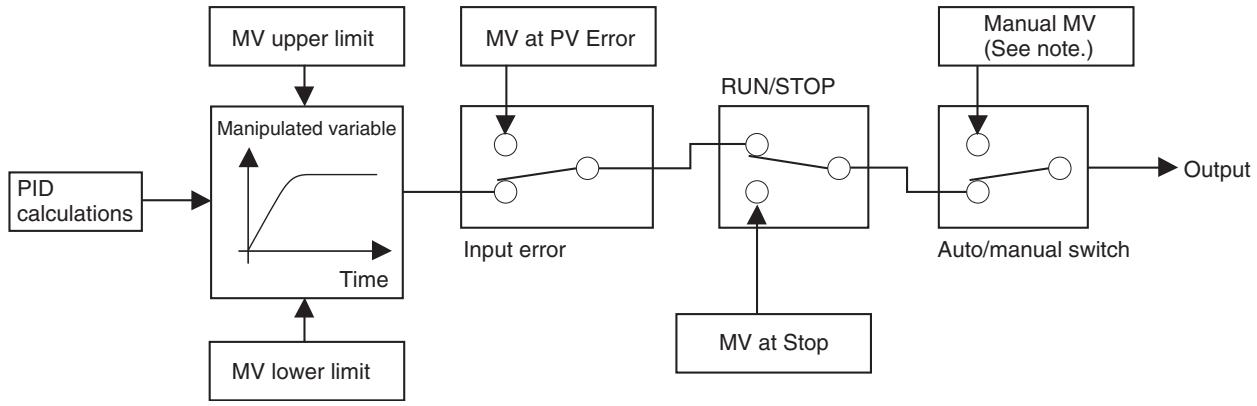
Note When the Manual MV Limit Enable parameter is set to ON, the setting range will be the MV lower limit to the MV upper limit.
4-17 Using the Extraction of Square Root Parameter
Extraction of Square Roots
Extraction of Square Root Enable
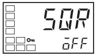
Extraction of Square Root Low-cut Point
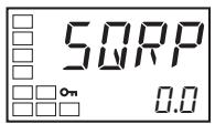
- For analog inputs, the Extraction of Square Root parameter is provided for inputs so that differential pressure-type flow meter signals can be directly input.
- The default setting for the Extraction of Square Root parameter is OFF. The Extraction of Square Root Enable parameter must be set to ON in order to use this function.
- If the PV input (i.e., the input before extracting the square root) is higher than 0.0% and lower than the low cut point set in the Extraction of Square Root Low-Cut Point parameter, the results of extracting the square root will be 0.0% . If the PV input is lower than 0.0% or higher than 100.0% , extraction of the square root will not be executed, so the result will be equal to the PV input. The low-cut point is set as normalized data for each input, with 0.0 as the lower limit and 100.0 as the upper limit for the input setting range.
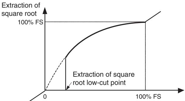
Argument 1 (Input Data)
| Parameter name | Setting rage | Unit | Default |
| Extraction of Square Root Enable | OFF: Disabled, ON: Enabled | --- | OFF |
| Extraction of Square Root Low-cut Point | 0.0 to 100.0 | % | 0.0 |
Operating Procedure
This procedure sets the Extraction of Square Root Low-cut Point parameter to 10.0% .
Operation Level
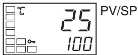
Initial Setting Level
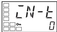
Input Type
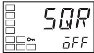
Extraction of Square Root Enable

Extraction of Square Root Enable
Operation Level
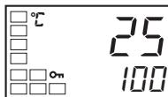
PV/SP
Adjustment Level
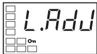
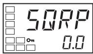
Extraction of Square Root Low-cut Point
- Press the Key for at least three seconds to move from the operation level to the initial setting level.
- Press the Key to select the Extraction of Square Root Enable parameter.
- Use the Key to select ON.
- Press the Key for at least one second to move from the initial setting level to the operation level.
- Press the Key to move from the operation level to the adjustment level.
- Select the Extraction of Square Root Low-cut Point parameter by pressing the 回 Key.

Extraction of Square Root Low-cut Point
Operation Level
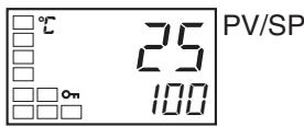
- Use the Key to set the parameter to 10.0.
- Press the Key to return to the operation level.
4-18 Setting the Width of MV Variation
MV Change Rate Limit
MV Change Rate Limit (Heating)
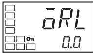
- The MV change rate limit sets the maximum allowable width of change in the MV per second. If the change in the MV exceeds this setting, the MV will be changed by the MV change rate limit until the calculated value is reached. This function is disabled when the setting is 0.0.
- The MV change rate limit does not function in the following situations:
In manual mode
- During ST execution (Cannot be set when ST is ON.)
- During AT execution
During ON/OFF control
- While stopped (during MV at Stop output)
- During MV at PV Error output
| Parameter name | Setting rage | Unit | Default |
| MV Change Rate Limit | 0.0 to 100.0 | %/s | 0.0 |
Operating Procedure
This procedure sets the MV change rate limit to 5.0% . The related parameters are as follows:
$$ P I D \cdot O N / O F F = P I D $$
$$ S T = O F F $$
Operation Level
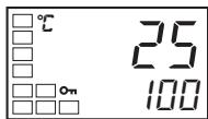
PV/SP
Initial Setting Level
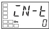
Input Type
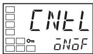
PID:ON/OFF
- Press the Key for at least three seconds to move from the operation level to the initial setting level.
- Select the PID ON/OFF parameter by pressing the Key.
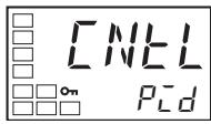
PID-ON/OFF
- Use the Key to select 2-PID control.
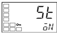
ST
- Press the Key to select the ST parameter.
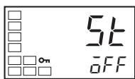
ST
- Press the 一 Key to select OFF.
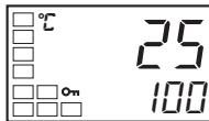
Operation Level
PV/SP
- Press the Key for at least one second to move from the initial setting level to the operation level.
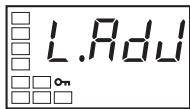
Adjustment Level
- Press the l Key to move from the operation level to the adjustment level.
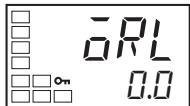
MV
Change
Rate Limit
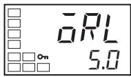
MV
Change
Rate Limit
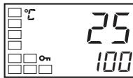
Operation Level
PV/SF
-
Press the Key to select the MV Change Rate Limit parameter.
-
Use the Key to set the parameter to 5.0.
-
Press the Key to return to the operation level.
4-19 Setting the PF Key
4-19-1 PF Setting (Function Key)
PF Setting
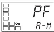
- Pressing the PF Key for at least one second executes the operation set in the PF Setting parameter (E5AN/EN only).
| Set value | Symbol | Setting | Function |
| OFF | aFF | Disabled | Does not operate as a function key. |
| RUN | RUN | RUN | Specifies RUN status. |
| STOP | sTeP | STOP | Specifies STOP status. |
| R-S | R-5 | RUN/STOP reverse operation | Specifies reversing the RUN/STOP operation status. |
| AT-2 | Rt-2 | 100% AT Execute/Cancel | Specifies reversing the 100% AT Execute/Cancel status. (See note 1.) |
| AT-1 | Rt-1 | 40% AT Execute/Cancel | Specifies reversing the 40% AT Execute/Cancel status. (See note 1.) |
| LAT | LRe | Alarm Latch Cancel | Specifies canceling all alarm latches. (See note 2.) |
| A-M | R-M | Auto/Manual | Specifies reversing the Auto/Manual status. (See note 3.) |
| PFDP | PFdP | Monitor/Setting Item | Specifies the monitor/setting item display. Select the monitor setting item according to the Monitor/Setting Item 1 to 5 parameters (advanced function setting level). |
Note
(1) When AT cancel is specified, it means that AT is cancelled regardless of whether the AT currently being executed is 100% AT or 40% AT.
(2) Alarms 1 to 3, heater burnout, HS alarms, and heater overcurrent latches are cancelled.
(3) For details on auto/manual operations using the PF Key, refer to 4-13 Performing Manual Control.
(4) Pressing the PF Key for at least one second executes operation according to the set value. When the Monitor/Setting Item parameter is selected, however, the display is changed in order from Monitor/Setting Item 1 to 5 each time the key is pressed.
(5) This function is enabled when PF Key Protect is OFF.
Monitor/Setting Item
Monitor/Setting Item 1
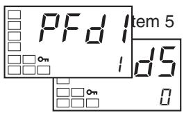
Setting the PF Setting parameter to the Monitor/Setting Item makes it possible to display monitor/setting items using the function key. The following table shows the details of the settings. For setting (monitor) ranges, refer to the applicable parameter.
| Set value | Setting | Remarks | |
| Monitor/Setting | Symbol | ||
| 0 | Disabled | --- | |
| 1 | PV/SP/Multi-SP | Can be set. (SP) | --- |
| 2 | PV/SP/MV (See note.) | Can be set. (SP) | --- |
| 3 | PV/SP /Soak time remain | Can be set. (SP) | --- |
| 4 | Proportional band (P) | Can be set. | P |
| 5 | Integral time (I) | Can be set. | <sup>1</sup> |
| 6 | Derivative time (D) | Can be set. | d |
| 7 | Alarm value 1 | Can be set. | RL - I |
| 8 | Alarm value upper limit 1 | Can be set. | RL IH |
| 9 | Alarm value lower limit 1 | Can be set. | RL IL |
| 10 | Alarm value 2 | Can be set. | RL - 2 |
| 11 | Alarm value upper limit 2 | Can be set. | RL 2H |
| 12 | Alarm value lower limit 2 | Can be set. | RL 2L |
| 13 | Alarm value 3 | Can be set. | RL - 3 |
| 14 | Alarm value upper limit 3 | Can be set. | RL 3H |
| 15 | Alarm value lower limit 3 | Can be set. | RL 3L |
Note For details on MV settings for heating and cooling control, refer to MV Display for Heating and Cooling Control on page 84.
Setting Monitor/Setting Items
Pressing the PF Key in either the operation or adjustment level displays the applicable monitor/setting items. Press the PF Key to display in order Monitor/Setting Items 1 to 5. After Monitor/Setting Item 5 has been displayed, the display will switch to the top parameter in the operation level.
Note
(1) Items set as disabled in the Monitor/Setting Items 1 to 5 parameters will not be displayed, and the display will skip to the next enabled setting.
(2) While a monitor/setting item is being displayed, the display will be switched to the top parameter in the operation level if the 一 Key or the Key is pressed.
Operating Procedure
This procedure sets the PF Setting parameter to PFDP, and the Monitor/Setting Item 1 parameter to 7 (Alarm Value 1).
Operation Level
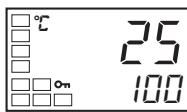
PV/SP
Initial Setting Level
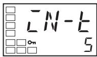
Input Type
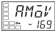
Move to Advanced Function Setting Level
- Press the Key for at least three seconds to move from the operation level to the initial setting level.
- Select the Move to Advanced Function Setting Level parameter by pressing the 回 Key.
Advanced Function Setting Level
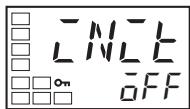
Parameter Initialization
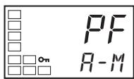
PF Setting
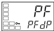
PF Setting
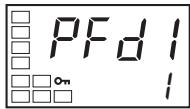
Monitor/Setting Item 1
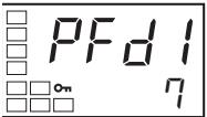
Monitor/Setting Item 1
Initial Setting Level
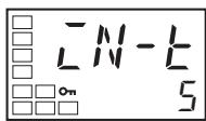
Input Type
Operation Level
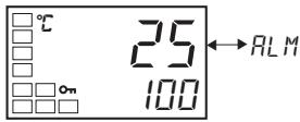
Monitor/Setting Item Level
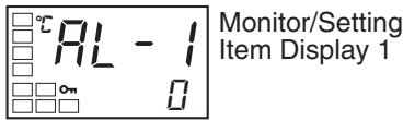
- Press the Key to enter the password (-169). It is possible to move to the advanced function setting level by either pressing the Key or waiting two seconds without pressing any key.
- Press the Key to select the PF Setting parameter.
- Press the Key to select PFDP (Monitor/Setting Item).
- Press the Key to select the Monitor/Setting Item 1 parameter.
- Press the Key to select 7 (Alarm Value 1).
- Press the Key for at least one second to move from the advanced function setting level to the initial setting level.
- Press the Key for at least one second to move from the initial setting level to the operation level.
- Press the PF Key to display Alarm Value 1.
4-20 Counting Control Output ON/OFF Operations
4-20-1 Control Output ON/OFF Count Function
With Control Output 1 and 2 ON/OFF outputs (relay outputs or voltage outputs for driving SSR), the number of times that a control output turns ON and OFF can be counted. Based on the control output ON/OFF count alarm set value, an alarm can be output and an error can be displayed if the set count value is exceeded.
The default setting of the Control Output ON/OFF Alarm Setting parameter is 0. ON/OFF operations are not counted when this parameter is set to 0. To enable counting ON/OFF operations, change the setting to a value other than 0.
Control Output ON/OFF Counter Monitor Function
This function is not displayed when the Control Output 1 ON/OFF Alarm Setting and the Control Output 2 ON/OFF Alarm Setting parameter are set to 0, or when the control outputs are set for linear outputs.
| Parameter name | Setting range | Unit | Default |
| Control Output 1 ON/OFF Count Monitor | 0 to 9999 | 100 times | 0 |
| Control Output 2 ON/OFF Count Monitor | 0 to 9999 | 100 times | 0 |
Display When ON/OFF Count Alarm Occurs
When an ON/OFF count alarm occurs, the PV display in the No. 1 display shown below alternates with the RRLM display on the No. 2 display.
PV
- PV/SP (Including the items displayed by setting the "PV/SP" Display Screen Selection parameter.)
- PV/Manual MV, PV/SP/Manual MV
- PV/SP displayed for the monitor/setting items
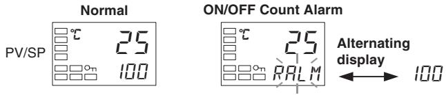
Control Output ON/OFF Count Alarm Function
If the ON/OFF counter exceeds the control output ON/OFF count alarm set value, an ON/OFF count alarm will occur. The alarm status can be assigned to a control output or an auxiliary output, or it can be displayed at the Controller. The ON/OFF count alarm set value function is disabled by setting the ON/OFF count alarm set value to 0.
| Parameter name | Setting range | Unit | Default |
| Control Output 1 ON/OFF Alarm Setting | 0 to 9999 | 100 times | 0 |
| Control Output 2 ON/OFF Alarm Setting | 0 to 9999 | 100 times | 0 |
ON/OFF Counter Reset Function
The ON/OFF counter can be reset for a specific control output.
| Parameter name | Setting range | Unit | Default |
| ON/OFF Counter Reset | 0: Disable the counter reset function. 1: Reset the control output 1 ON/OFF counter. 2: Reset the control output 2 ON/OFF counter. | --- | 0 |
Note After the counter has been reset, the control output ON/OFF count monitor value will be automatically returned to 0.
If an error occurs in the control output ON/OFF counter data, the ON/OFF count monitor value will be set to 9999 and an ON/OFF count alarm will occur. The alarm can be cleared by resetting the ON/OFF counter.
Operating Procedure
Initial Setting Level
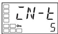
Input Type
Initial Setting Level
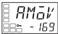
Move to Advanced Function Setting Level
Advanced Function Setting Level
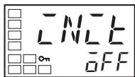
Parameter Initialization
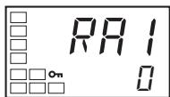
Control Output 1 ON/OFF Count Alarm Set Value
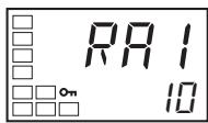
Control Output 1 ON/OFF Count Alarm Set Value
Initial Setting Level
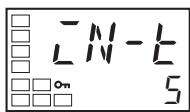
Input Type
Operation Level
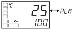
This procedure sets the Control Output 1 ON/OFF Alarm Setting parameter to 10 (1,000 times).
- Press the Key for at least three seconds to move from the operation level to the initial setting level.
- Select the Move to Advanced Function Setting Level parameter by pressing the 回 Key.
- Use the to enter the password ("-169"). It is possible to move to the advanced function setting level by either pressing the or waiting two seconds without pressing any key.
- Press the Key to select the Control Output 1 ON/OFF Count Alarm Set Value parameter.
- Use the Key to set the parameter to 10.
- Press the Key for at least one second to move to the initial setting level.
- Press the l Key for at least one second to move to the operation level.
4-21 Displaying PV/SV Status
4-21-1 PV and SV Status Display Functions
PV Status Display Function
The PV in the PV/SP, PV, or PV/Manual MV Display and the control and alarm status specified for the PV status display function are alternately displayed in 0.5-s cycles.
| Set value | Symbol | Function |
| OFF | OFF | No PV status display |
| Manual | MANU | MANU is alternately displayed during manual control. |
| Stop | STOP | STOP is alternately displayed while operation is stopped. |
| Alarm 1 | ALM1 | ALM1 is alternately displayed during Alarm 1 status. |
| Alarm 2 | ALM2 | ALM2 is alternately displayed during Alarm 2 status. |
| Alarm 3 | RLM3 | ALM3 is alternately displayed during Alarm 3 status. |
| Alarm 1 to 3 OR status | RLM | ALM is alternately displayed when Alarm 1, 2, or 3 is set to ON. |
| Heater Alarm (See note.) | HR | HA is alternately displayed when a heater burnout alarm, HS alarm, or heater over-current alarm is ON. |
- The default is OFF.
Note "HA" can be selected for models that do not support heater burnout detection, but the function will be disabled.
Example: When STOP Is Selected for the PV Status Display Function
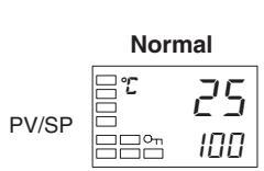
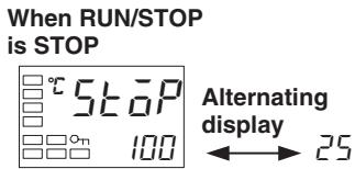
SV Status Display Function
The SP, Blank, or Manual MV in the PV/SP, PV, or PV/Manual MV Display and the control and alarm status specified for the SV status display function are alternately displayed in 0.5-s cycles.
| Set value | Symbol | Function |
| OFF | OFF | No SV status display |
| Manual | MANU | MANU is alternately displayed during manual control. |
| Stop | STOP | STOP is alternately displayed while operation is stopped. |
| Alarm 1 | ALM1 | ALM1 is alternately displayed during Alarm 1 status. |
| Alarm 2 | ALM2 | ALM2 is alternately displayed during Alarm 2 status. |
| Alarm 3 | ALM3 | ALM3 is alternately displayed during Alarm 3 status. |
| Alarm 1 to 3 OR status | ALM | ALM is alternately displayed when Alarm 1, 2, or 3 is set to ON. |
| Heater Alarm (See note.) | HR | HA is alternately displayed when a heater burnout alarm, HS alarm, or heater over-current alarm is ON. |
- The default is OFF.
Note "HA" can be selected for models that do not support heater burnout detection, but the function will be disabled.
Example: When ALM1 Is Selected for the SV Status Display Function
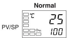
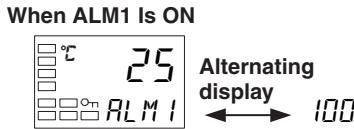
Operating Procedure
Initial Setting Level
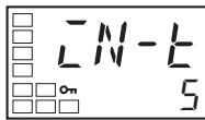
Input Type
Initial Setting Level

Move to Advanced Function Setting Level
Advanced Function Setting Level
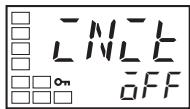
Parameter Initialization
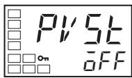
PV Status Display Function
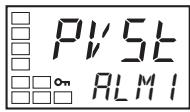
PV Status Display Function
Initial Setting Level
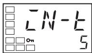
Input Type
Operation Level
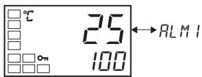
This procedure sets the PV Status Display Function parameter to ALM1.
- Press the Key for at least three seconds to move from the operation level to the initial setting level.
- Select the Move to Advanced Function Setting Level parameter by pressing the 回 Key.
- Use the Key to enter the password (-169). It is possible to move to the advanced function setting level by either pressing the Key or waiting two seconds without pressing any key.
- Press the Key to select the PV Status Display Function parameter.
- Press the Key to select ALM1.
- Press the Key for at least one second to move to the initial setting level.
- Press the Key for at least one second to move to the operation level. If the Alarm 1 status is ON, PV and ALM1 will be alternately displayed.
4-22 Logic Operations
4-22-1 The Logic Operation Function (CX-Thermo)
- The logic operation function logically calculates as 1 or 0 the Controller status (alarms, SP ramp, RUN/STOP, auto/manual, etc.) and the external event input status, and outputs the results to work bits. The work bit status can be output to auxiliary or control outputs, and operating status can be switched according to the work bit status.
- Work bit logic operation can be set from 1 to 8. Set them to No operation (Always OFF) (the default) when the work bits are not to be used. When logic operations are being used, a dot will be displayed on the No. 2 display of the adjustment level display
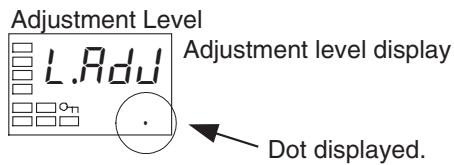
4-22-2 Using Logic Operations
Logic operations are set using the CX-Thermo.
Starting Logic Operations
There are two ways to start logic operations.
- Select Logic Operation Editor from the CX-Thermo tree, and click the Start Button.

- Select Logic Operation Editor from the CX-Thermo Options Menu.
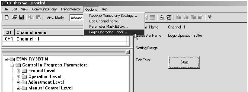
Making the Settings
The following display will appear on the Logic Operation Editor Setting Window. Set each of the parameters.
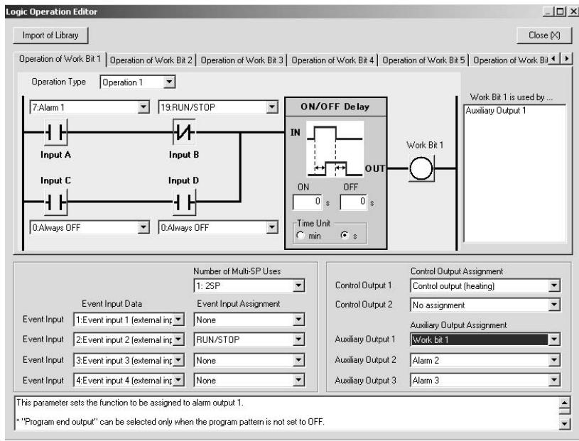
1,2,3... 1. Displaying the Library Import Dialog Box
Logic operation samples for specific cases are set in the library in advance. Examples of settings for specific cases are loaded by selecting them from the library list and clicking the OK Button.
Example: Selecting Library 1

2. Switching Work Bit Operations
Select the work bit logic operations from the Operation of Work Bit 1 to Operation of Work Bit 8 Tab Pages.
3. Selecting the Operation Type
From one to four operations are supported. If work bits are not to be used, set them to No operation (Always OFF) (the default).
- No operation (Always OFF)
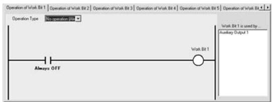
Operation 1
(A and B) or (C and D) When conditions A and B or conditions C and D are satisfied
Operation 2
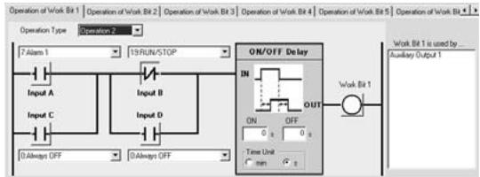
(A or C) and (B or D)
When condition A or C and condition B or D are satisfied
Operation 3
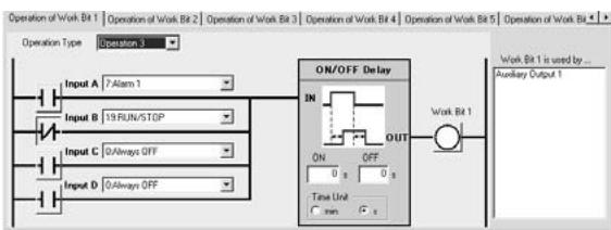
A or B or C or D When condition A, B, C or D is satisfied
Operation 4
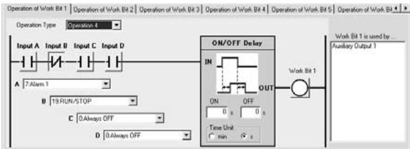
A and B and C and D When conditions A, B, C and D are all satisfied
4. Selecting Input Assignments
Select the input assignment for the work bit logic operation from the following settings.
| Parameter name | Setting range |
| Work Bit 1 Input Assignment A | 0: Always OFF1: Always ON2: ON for one cycle when power is turned ON3: Event input 1 (external input) (See note 1.)4: Event input 2 (external input) (See note 1.)5: Event input 3 (external input) (See note 1.)6: Event input 4 (external input) (See note 1.)7: Alarm 18: Alarm 29: Alarm 310: Control output ON/OFF count alarm (See note 2.)11: Control output (heating)12: Control output (cooling)13: Input error14: Disabled15: HB (heater burnout) alarm16: HS alarm17: OC (heater overcurrent) alarm18: Auto/Manual19: RUN/STOP20: Disabled21: Program start22: AT Execute/Cancel23: SP ramp operating24: Multi-SP (bit 0)25: Multi-SP (bit 1)26: Disabled27: Program end output28: Work bit 129: Work bit 230: Work bit 331: Work bit 432: Work bit 533: Work bit 634: Work bit 735: Work bit 8 |
| Work Bit 1 Input Assignment B | Same as for work bit 1 input assignment A |
| Work Bit 1 Input Assignment C | Same as for work bit 1 input assignment A |
| Work Bit 1 Input Assignment D | Same as for work bit 1 input assignment A |
| to | to |
| Work Bit 8 Input Assignment D | Same as for work bit 1 input assignment A |
Note (1) The event inputs that can be used depend on the Controller model.
(2) Turns ON when either the control output 1 or 2 ON/OFF count alarm is ON.
- Switching between Normally Open and Normally Closed for Inputs A to D Click the condition to switch between normally open and normally closed inputs A to D.
| Normally open | Normally closed |
| - | - | - | - |
- Switching between Normally Open and Normally Closed for Work Bits Click the condition to switch between normally open and normally closed work bits.
| Normally open | Normally closed |
| -○- | -∅- |
- Setting ON Delay Times
When an input with ON delay turns ON, the output will turn ON after the set delay time has elapsed. The setting range is 0 to 9,999. The default is 0 (disabled).
- Setting OFF Delay Times
When an input with OFF delay turns OFF, the output will turn OFF after the set delay time has elapsed. The setting range is 0 to 9,999. The default is 0 (disabled).
- Switching ON/OFF Delay Time Unit
Select either seconds or minutes for the ON/OFF delay time unit. The default is seconds.
- Selecting the Number of Multi-SP Uses
Select the number of Multi-SP uses from 0 to 2.
- Changing Event Input Data
Select the event input conditions from the following setting ranges.
| Parameter name | Setting range |
| Event Input Data 1 | 0: Not assigned.1: Event input 1 (external input)2: Event input 2 (external input)3: Event input 3 (external input)4: Event input 4 (external input)5: Work bit 16: Work bit 27: Work bit 38: Work bit 49: Work bit 510: Work bit 611: Work bit 712: Work bit 8 |
| Event Input Data 2 | Same as for event input data 1 |
| Event Input Data 3 | Same as for event input data 1 |
| Event Input Data 4 | Same as for event input data 1 |
Note The event input data can be changed from the default setting even if there is no event input terminal (external input). By changing the default setting, the event input assignment parameters will be displayed at the Controller display and can be set from the Controller.
- Changing the Event Input Assignment Function
Select the setting for the event input assignment.
When a work bit is selected as event input data, Communications Write Enable/Disable cannot be assigned to an event input.
- Changing Control Output and Auxiliary Output Settings
Control output and auxiliary output assignments can be changed. The items that can be changed depend on the Controller model. For details, refer to 3-5-3 Assigned Output Functions.
Assigning a work bit to either a control output or to an auxiliary output is also considered to be the same as assigning an alarm. For example, if work bit 1 is set for the Auxiliary Output 1 Assignment parameter, then alarms 1 to 3 have been assigned.
- Displaying Parameter Guides
A description of the parameters can be displayed.
- Displaying the Work Bit Use Destinations
Display a list of destinations where the work bits are used.
Operating Procedure
This procedure uses event input 2 to change to RUN or STOP.
Event input 2 ON: RUN
Event input 2 OFF: STOP
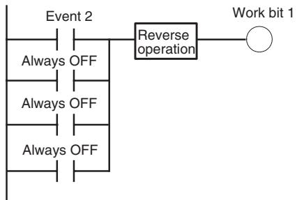
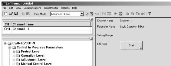
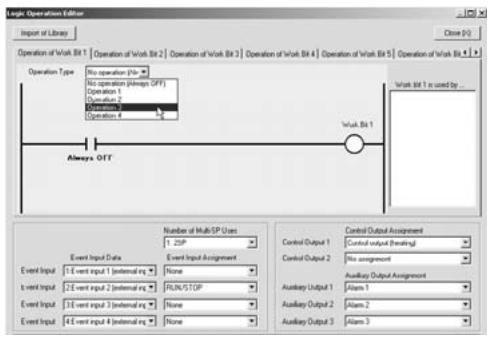
- Select Logic Operation Editor from the CX-Thermotree, and click the Start Button.
- The Logic Operation Editor will be displayed. Confirm that the screen for work bit 1 is displayed, and select Operation 3 from the Operation Type Field.
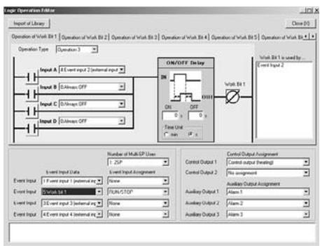
- Set the operation by selecting one of the following:
Work bit 1 input assignment A = 4 : Event input 2 (ternal input)
Work bit 1 input assignment B = 0 : Always OFF
Work bit 1 input assignment C = 0 : Always OFF
Work bit 1 input assignment D = 0 : Always OFF - Invert work bit 1. Click (Normally open) to change it to (Normally closed).
- Assign RUN/STOP to event input 2. Set “5: Work bit 1” for the event input data for event input 2, and set “RUN/STOP” for the assignment function.
- Closing the Logic Operation Editor Dialog Box Click the Close Button.
This completes the procedure for setting parameters using the CX-Thermo. Transfer the settings to the Controller to set the Controller. Refer to CX-Thermo help for the procedure to transfer the settings.
Operating Procedure
This procedure outputs alarm 1 status to auxiliary output 1 during operation (RUN). A library object is used to make the setting.
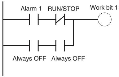
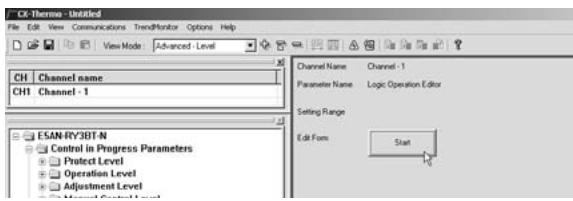
- Select Logic Operation Editor from the CX-Thermotree, and click the Start Button.
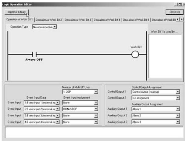
- Click the Import of Library Button.
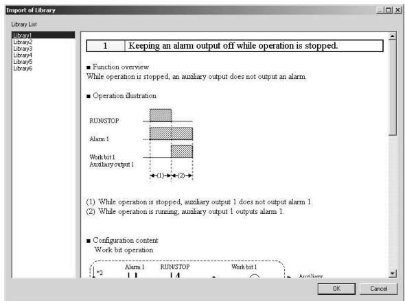
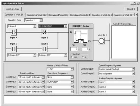
- Select Library 1 from the library list, and then click the OK Button.
Confirm the following settings, and then click the OK Button.
Work bit 1 operation type: Operation 1
Work bit 1 input assignment A = 7 : Alarm 1
Work bit 1 input assignment B = 19: Invert for RUN/ STOP
Work bit 1 input assignment C = 0 : Always OFF
Work bit 1 input assignment D = 0 : Always OFF
Auxiliary output 1 = Work bit 1
- Closing the Logic Operation Editor Dialog Box Click the Close Button.
This completes the procedure for setting parameters using the CX-Thermo. Transfer the settings to the Controller to set the Controller. Refer to CX-Thermo help for the procedure to transfer the settings.
SECTION 5 Parameters
This section describes the individual parameters used to setup, control, and monitor operation.
5-1 Conventions Used in this Section 158
5-1-1 Meanings of Icons Used in this Section 158
5-1-2 About Related Parameter Displays. 158
5-1-3 The Order of Parameters in This Section 158
5-1-4 Alarms. 158
5-2 Protect Level 159
5-3 Operation Level. 163
5-4 Adjustment Level 177
5-5 Monitor/Setting Item Level. 196
5-6 Manual Control Level 197
5-7 Initial Setting Level. 199
5-8 Advanced Function Setting Level 218
5-9 Communications Setting Level 255
5-1 Conventions Used in this Section
5-1-1 Meanings of Icons Used in this Section

Describes the functions of the parameter.
Describes the setting range and default of the parameter.
Used to indicate parameters used only for monitoring.
Describes the parameter settings, such as those for Operation Commands, and procedures.

Used to indicate information on descriptions in which the parameter is used or the names of related parameters.
5-1-2 About Related Parameter Displays
Parameters are displayed only when the conditions for use given on the right of the parameter heading are satisfied. Protected parameters are not displayed regardless of the conditions for use, but the settings of these parameters are still valid.

5-1-3 The Order of Parameters in This Section
Parameters are described level by level.
The first page of each level describes the parameters in the level and the procedure to switch between parameters.
5-1-4 Alarms
It will be specified in this section when alarms are set for the Control Output 1 or 2 Assignment parameters, or for the Auxiliary Output 1 or 3 Assignment parameters. For example, when alarm 1 is set for the Control Output 1 Assignment parameter, it will be specified that alarm 1 is assigned.
Assigning a work bit to either control output 1 or 2 or to auxiliary output 1 to 3 is also considered to be the same as assigning an alarm. For example, if work bit 1 is set for the Auxiliary Output 1 Assignment parameter, then alarms 1 to 3 have been assigned.
5-2 Protect Level
Four levels of protection are provided on the E5□N, operation/adjustment protect, initial setting/communications protect, setting change protect, and PF key protect (E5AN/EN only). These protect levels prevent unwanted operation of the keys on the front panel in varying degrees.
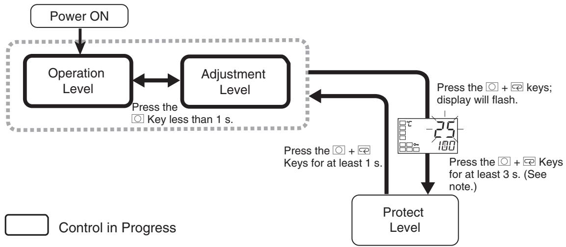
To move from the operation level to the protect level, press and Keys for three seconds (see note) or more.
Note The time taken to move to the protect level can be adjusted by changing the Move to Protect Level Time parameter setting.
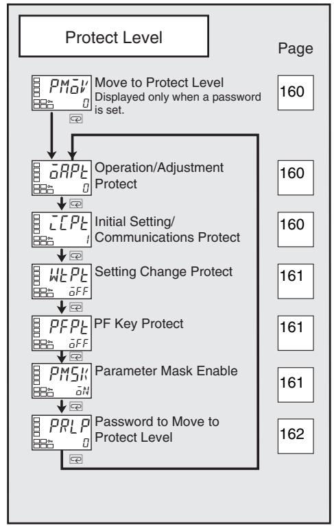
Parameters that are protected will not be displayed and their settings cannot be changed.
| PMov | Move to Protect Level | The Password to Move to Protect Level password must not be set to 0. |
| Function | The password to move to the protect level is entered for this parameter. · The password to move to the protect level (i.e., the password set for the Password to Move to Protect Level parameter) is entered for this parame- ter. · The Operation/Adjustment Protect parameter will be displayed if the cor- rect password is entered. | |
| See | ■ Related Parameters Password to move to protect level (protect level): Page 162 | |
| aRPl | Operation/Adjustment Protect | |
| cPLt | Initial Setting/Communications Protect | |
These parameters specify the range of parameters to be protected. Shaded settings are the defaults.
Operation/Adjustment Protect
The following table shows the relationship between set values and the range of protection.
| Level | Set value | ||||
| 0 | 1 | 2 | 3 | ||
| Operation Level | PV | Can be displayed | Can be displayed | Can be displayed | Can be displayed |
| PV/SP | Can be displayed and changed | Can be displayed and changed | Can be displayed and changed | Can be displayed | |
| Others | Can be displayed and changed | Can be displayed and changed | Cannot be dis-played and moving to other levels is not possible | Cannot be dis-played and moving to other levels is not possible | |
| Adjustment Level | Can be displayed and changed | Cannot be dis-played and moving to other levels is not possible | Cannot be dis-played and moving to other levels is not possible | Cannot be dis-played and moving to other levels is not possible | |
- Parameters are not protected when the set value is set to 0.
Initial Setting/Communications Protect
This protect level restricts movement to the initial setting level, communications setting level, and advanced function setting level.
| Set value | Initial setting level | Communications setting level | Advanced function setting level |
| 0 | Possible to reach | Possible to reach | Possible to reach |
| 1 | Possible to reach | Possible to reach | Not possible to reach |
| 2 | Not possible to reach | Not possible to reach | Not possible to reach |
| The Event Input Assignment 1 and 2 parameters must not be set to "set- ting change enable/disable." | ||
| This parameter specifies the range of data to be protected. The shaded cell indicates the default. | ||
| ■ Change Setting Protect Changes to settings using key operations are restricted. When enabling and disabling of setting changes by event inputs assignment 1 and 2 is selected, this parameter is not displayed. | ||
| Setting range | Default | |
| ōN: Enabled,ōFF: Disabled | ōN | |
| Set value | Description | |
| OFF | Settings can be changed using key operations. | |
| ON | Settings cannot be changed using key operations. (The protect level settings, however, can be changed.) | |
| · The all protect indication (ōN) will light when setting is ON. | ||
| PFPE | PF Key Protect | The Controller must have a PF Key (E5AN/EN). |
| Function | ■ PF Key Protect This parameter enables and disables PF Key operation (E5AN/EN only). | |
| Setting | Set value | Description |
| OFF | PF Key enabled | |
| ON | PF Key disabled (Operation as a function key is prohibited.) | |
| · The shaded cell indicates the default. | ||
| PMSK | Parameter Mask Enable | This parameter is displayed only when a parameter mask has been set from the Setup Tool. |
| Function | · This parameter turns the parameter mask function ON and OFF. | |
| Setting | Setting range | Default |
| ōN: Enabled,ōFF: Disabled | ōN | |
PRLF
Password to Move to Protect Level
This parameter is used to set the password to move to the protect level.
- To prevent setting the password incorrectly, the and Keys or and Keys must be pressed simultaneously to set the password.
| Setting range | Default |
| -1999 to 9999 | 0 |
- Set this parameter to 0 when no password is to be set.

Related Parameters
Move to protect level (protect level): Page 160
Note Protection cannot be cleared or changed without the password. Be careful not to forget it. If you forget the password, contact your OMRON sales representative.
5-3 Operation Level
Display this level to perform control operations on the E5□N. You can set alarm values, monitor the manipulated variable, and perform other operations in this level.
In the advanced function setting level, you can set a parameter to hide or show the set points.
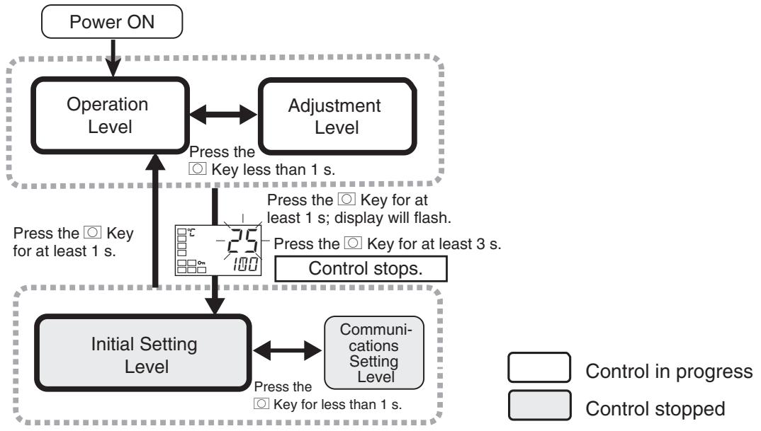
This level is displayed immediately after the power is turned ON.
To move to other levels, press the Key or the and Keys.
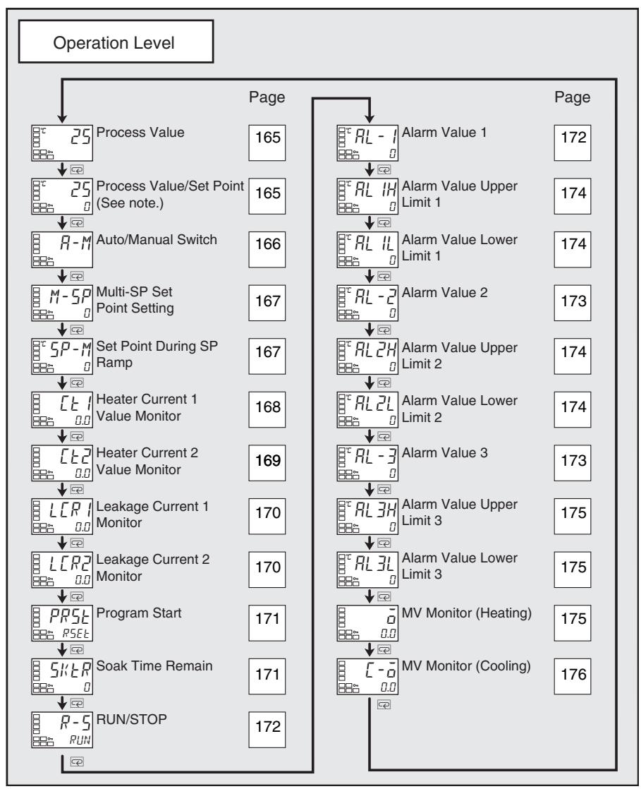
Note For details on the displays of Controllers with a No. 3 display (E5AN/EN), refer to Process Value/Set Point on page 165.
| Process Value | The Additional PV Display parameter must be set to ON. | |
| Function | The process value is displayed on the No. 1 display, and nothing is displayed on the No. 2 and No. 3 (E5AN/EN only) displays. | |
| Monitor | Monitor range | |
| Process value | Temperature: According to indication range for each sensor. Analog: Scaling lower limit -5% FS to Scaling upper limit +5% FS (Refer to page 303.) | |
| During temperature input, the decimal point position depends on the currently selected sensor, and during analog input it depends on the Decimal Point parameter setting. The default setting is for a K thermocouple (5). An S.E.R.R error will be displayed if the input type setting is incorrect. To clear the S.E.R.R error, correct the input type or wiring, and then cycle the power. | ||
| See | ■ Related Parameters Input type: Page 200, Set point upper limit, Set point lower limit: Page 203 (initial setting level) | |
Process Value/Set Point (Display 1)
Process Value/Set Point (Display 2)
(E5AN/EN only)
Function
The process value is displayed on the No. 1 display, and the set point is displayed on the No. 2 display.
Monitor
| Monitor range | Unit | |
| Process value | Temperature: According to indication range for each sensor. Analog: Scaling lower limit -5% FS to Scaling upper limit +5% FS (Refer to page 303.) | EU |
| Setting range | Unit | |
| Set point | SP lower limit to SP upper limit | EU |
During temperature input, the decimal point position depends on the currently selected sensor, and during analog input it depends on the Decimal Point parameter setting.
No. 3 Display (E5AN/EN)
The following table shows the contents of the No. 3 display, according to the setting of the PV/SP Display Screen Selection parameter.
| Set value | Display contents |
| 0 | Only the PV and SP are displayed. (The No. 3 display is not shown.) |
| 1 | PV/SP/Multi-SP and PV/SP/MV are displayed in order. |
| 2 | PV/SP/MV and PV/SP/Multi-SP are displayed in order. |
| 3 | Only PV/SP/Multi-SP are displayed. |
| 4 | PV/SP/MV are displayed |
| 5 | PV/SP/Multi-SP and PV/SP/Soak time remain are displayed in order. |
| 6 | PV/SP/MV and PV/SP/Soak time remain are displayed in order. |
| 7 | Only PV/SP/Soak time remain are displayed. |
A 2-level display is set when shipped from the factory.
A 3-level display is activated if parameters are initialized.
When 1, 2, 5, or 6 is selected, press the Key to display PV/SP (Display 2).
Example: When the PV/SP Display Screen Selection Parameter Is Set to 2

See
Related Parameters
Input type: Page 200, Set point upper limit, Set point lower limit: Page 203 (initial setting level)
PV/SP display screen selection (advanced function setting level): Page 249
R-M
Auto/Manual Switch
The Event Input Assignment 1 and 2 parameters must not be set to Auto/ Manual and the Auto/Manual Select Addition parameter must be set to ON.
The control must be set to 2-PID control.

Operation
- This parameter switches the Controller between automatic and manual modes.
- If the Key is pressed for at least 3 seconds when the Auto/Manual Switch parameter is displayed, the manual mode will be entered and the manual control level will be displayed.
- This parameter will not be displayed if an event input is set to "MANU" (auto/manual).
See
Related Parameters
PID ON/OFF (initial setting level): Page 204
Auto/manual select addition (advanced function setting level): Page 234
| M-5P | Multi-SP Set Point Setting (Set Points 0 to 3) | The Multi-SP Uses parameter must be set to ON. |
| Function | To use the multi-SP function, preset the four set points (SP 0 to 3) in the adjustment level, and then switch the set point either by operating the keys or by using external input signals (event inputs). This parameter is used to select set points 0 to 3. | |
| 5P-M | Set Point During SP Ramp | The SP Ramp Set Value parameter must not be set to OFF. The ST parameter must be set to OFF. |
| Function | This parameter monitors the set point during SP ramp operation. A ramp is used to restrict the change width of the set point as a rate of change. This parameter is displayed when a set value is input for the SP Ramp Set Value parameter (adjustment level). When not in ramp operation, the set point will be the same as the one displayed for the Process Value/Set Point parameter. | |
| Monitor | Monitor range | Unit |
| SP: SP lower limit to SP upper limit | EU | |
| See | ■ Related Parameters Process value/set point (operation level): Page 165 SP ramp set value (adjustment level): Page 193 Set point upper limit, Set point lower limit (initial setting level): Page 203 | |
| Heater Current 1 Value Monitor | Heater burnout, HS alarm, and heater overcurrent detection must be supported. Alarm 1 must be assigned. The Heater Burnout Detection or Heater Overcurrent Use parameter must be set to ON. | |
| Function | This parameter measures the heater current from the CT input used for detecting heater burnout. This parameter measures and displays the heater current value. • Heater burnouts and heater overcurrent are not detected if the control output (heating) ON time is 100 ms or less. | |
| Monitor | Monitor range | Unit |
| 0.0 to 55.0 | A | |
| ● FFFF is displayed when 55.0 A is exceeded. ● If a heater burnout detection 1 or heater overcurrent detection 1 alarm is output, the HA indicator will light and the No. 1 display for the heater cur- rent 1 value monitor will flash. | ||
| See | ■ Related Parameters Heater burnout detection 1, Heater burnout detection 2 (adjustment level): Pages 181, and 183 HB ON/OFF (advanced function setting level): Page 222 Heater overcurrent detection 1, Heater overcurrent detection 2 (adjustment level): Pages 181, and 183 Heater overcurrent use (advanced function setting level): Page 246 Error Displays [E:]: Page 283 | |
| Heater Current 2 Value Monitor | Heater burnout, HS alarm, and heater overcurrent detection must be supported (two CTs). Alarm 1 must be assigned. The Heater Burnout Detection or Heater Overcurrent Use parameter must be set to ON. | |
| Function | This parameter measures the heater current from the CT input used for detecting heater burnout. This parameter measures and displays the heater current value. • Heater burnouts and heater overcurrent are not detected if the control output (heating) ON time is 100 ms or less. | |
| Monitor | Monitor range | Unit |
| 0.0 to 55.0 | A | |
| ● FFFF is displayed when 55.0 A is exceeded. ● If a heater burnout detection 2 or heater overcurrent detection 2 alarm is output, the HA indicator will light and the No. 1 display for the heater cur- rent 2 value monitor will flash. | ||
| See | ■ Related Parameters Heater burnout detection 1, Heater burnout detection 2 (adjustment level): Pages 181, and 183 HB ON/OFF (advanced function setting level): Page 222 Heater overcurrent detection 1, Heater overcurrent detection 2 (adjustment level): Pages 181, and 183 Heater overcurrent use (advanced function setting level): Page 246 Error Displays [t-2]: Page 283 | |
| LCRI | Leakage Current 1 Monitor | Heater burnout, HS alarms, and heater overcurrent detection must be supported. Alarm 1 must be assigned. The HS Alarm Use parameter must be set to ON. |
| Function | This parameter measures the heater current from the CT input used for detecting SSR short-circuits. The heater current is measured and the leakage current 1 monitor is displayed. • HS alarms are not detected if the control output (heating) OFF time is 100 ms or less. | |
| Monitor | Monitor range | Unit |
| 0.0 to 55.0 | A | |
| • FFFF is displayed when 55.0 A is exceeded. • If an HS alarm 1 alarm is output, the HA indicator will light and the No. 1 display for the leakage current 1 monitor will flash. | ||
| See | ■ Related Parameters HS alarm 1, HS alarm 2 (adjustment level): Page 184 Failure detection (advanced function setting level): Page 235 Error Displays LCR: Page 283 | |
| LCRI2 | Leakage Current 2 Monitor | Heater burnout, HS alarms, and heater overcurrent detection must be supported (two CTs). Alarm 1 must be assigned. The HS Alarm Use parameter must be set to ON. |
| Function | This parameter measures the heater current from the CT input used for detecting SSR short-circuits. This parameter measures and displays the heater current value. • HS alarms are not detected if the control output (heating) OFF time is 100 ms or less. | |
| Monitor | Monitor range | Unit |
| 0.0 to 55.0 | A | |
| • FFFF is displayed when 55.0 A is exceeded. • If an HS alarm 2 alarm is output, the HA indicator will light and the No. 1 display for the leakage current 2 monitor will flash. | ||
| See | ■ Related Parameters HS alarm 1, HS alarm 2 (adjustment level): Page 184 HS alarm use (advanced function setting level): Page 235 Error Displays LCR2: Page 283 | |
| PRSE | Program Start | The Program Pattern parameter must not be set to OFF. | |
| Function | This parameter starts and stops the simple program function. · The RUN/STOP status will automatically switch to RUN when this param- eter is set to STRT. · The simple program will stop when this parameter is set to RSET. · This parameter will function as a monitor display for the start/stop status of the simple program if an event input is selected to start the simple pro- gram. | ||
| Operation | Setting range | Default | |
| RSET | Stops the simpler program. | RSET | |
| STRRT | Starts the simpler program. | ||
| See | ■ Related Parameters Soak time remain: Page 171, RUN/STOP: Page 172 (operation level) Soak time, Wait band (adjustment level): Page 191 Program pattern (initial setting level): Page 205 Soak time unit (advanced function setting level): Page 243 | ||
| SKIP | Soak Time Remain | The Program Pattern parameter must not be set to OFF. | |
| Function | · This parameter measures and displays the remaining time of the soak time for the simple program function. | ||
| Monitor | Monitor range | Unit | |
| 0 to 9999 | min or h | ||
| See | ■ Related Parameters Program start (operation level): Page 171 Soak time, Wait band (adjustment level): Page 191 Program pattern (initial setting level): Page 205 Soak time unit (advanced function setting level): Page 243 | ||
| R-5 | RUN/STOP | The Event Input Assignment 1 and 2 parameters must not be set to “RUN/STOP.” | |
| Operation | This parameter starts and stops the control operation. When RUN (RUN) is selected, control is started. When SToP (STOP) is selected, control is stopped. The STOP indicator will light when control. The default is RUN. | ||
| See | This parameter will not be displayed if an event input is set to “RUN/STOP.” | ||
| RL - I | Alarm Value 1 | Alarm 1 must be assigned. The alarm 1 type must not be 0, 1, 4, 5, or 12. | |
| Function | This parameter is set to one of the input values “X” in the alarm type list. · This parameter sets the alarm value for alarm 1. · During temperature input, the decimal point position depends on the currently selected sensor, and during analog input it depends on the Decimal Point parameter setting. | ||
| Setting | Setting range | Unit | Default |
| -1999 to 9999 | EU | 0 | |
| See | ■ Related Parameters Input type: Page 200, Scaling upper limit, Scaling lower limit, Decimal point (initial setting level): Page 202 (initial setting level) Alarm 1 type (initial setting level): Page 207 Standby sequence reset: Page 221, Auxiliary output * open in alarm: Page 222, Alarm 1 hysteresis: Page 209, Alarm 1 latch: Page 227 (advanced function setting level) | ||
| RL-2 | Alarm Value 2 | Alarm 2 must be assigned. The alarm 2 type must not be 0, 1, 4, 5, or 12. | |
| Function | This parameter is set to one of the input values “X” in the alarm type list. · This parameter sets the alarm value for alarm 2. · During temperature input, the decimal point position depends on the cur- rently selected sensor, and during analog input it depends on the Decimal Point parameter setting. | ||
| Setting | Setting range | Unit | Default |
| -1999 to 9999 | EU | 0 | |
| See | ■ Related Parameters Input type: Page 200, Scaling upper limit, Scaling lower limit, Decimal point (initial setting level): Page 202 (initial setting level) Alarm 2 type (initial setting level): Page 209 Standby sequence reset: Page 221, Auxiliary output * open in alarm: Page 222, Alarm 2 hysteresis: Page 209, Alarm 2 latch: Page 227 (advanced func- tion setting level) | ||
| RL-3 | Alarm Value 3 | Alarm 3 must be assigned. The alarm 3 type must not be 0, 1, 4, 5, or 12. | |
| Function | This parameter is set to one of the input values “X” in the alarm type list. · This parameter sets the alarm value for alarm 3. · During temperature input, the decimal point position depends on the cur- rently selected sensor, and during analog input it depends on the Decimal Point parameter setting. | ||
| Setting | Setting range | Unit | Default |
| -1999 to 9999 | EU | 0 | |
| See | ■ Related Parameters Input type: Page 200, Scaling upper limit, Scaling lower limit, Decimal point (initial setting level):Page 202 (initial setting level) Alarm 3 type (initial setting level): Page 210 Standby sequence reset: Page 221, Auxiliary output * open in alarm: Page 222, Alarm 3 hysteresis: Page 209, Alarm 3 latch: Page 227 (advanced func- tion setting level) | ||
| RL IH | Alarm Value Upper Limit 1 | Alarm 1 must be assigned. The alarm 1 type must not be 1, 4, or 5. | |
| RL IL | Alarm Value Lower Limit 1 | ||
| Function | These parameters independently set the alarm value upper and lower limits when the mode for setting the upper and lower limits is selected for the Alarm 1 Type parameter (initial setting level). · This parameter sets the upper and lower limit values of alarm 1. · During temperature input, the decimal point position depends on the currently selected sensor, and during analog input it depends on the Decimal Point parameter setting. | ||
| Setting | Setting range | Unit | Default |
| -1999 to 9999 | EU | 0 | |
| See | ■ Related Parameters Input type: Page 200, Scaling upper limit, Scaling lower limit, Decimal point: Page 202, Alarm 1 type: Page 207 (initial setting level), Standby sequence reset: Page 221, Auxiliary output * open in alarm: Page 222, Alarm 1 hysteresis: Page 209, Alarm 1 latch: Page 227 (advanced function setting level) | ||
| RL 2H | Alarm Value Upper Limit 2 | Alarm 2 must be assigned. The alarm 2 type must not be 1, 4, or 5. | |
| RL 2L | Alarm Value Lower Limit 2 | ||
| Function | These parameters independently set the alarm value upper and lower limits when the mode for setting the upper and lower limits is selected for the Alarm 2 Type parameter (initial setting level). · This parameter sets the upper and lower limit values of alarm 2. · During temperature input, the decimal point position depends on the currently selected sensor, and during analog input it depends on the Decimal Point parameter setting. | ||
| Setting | Setting range | Unit | Default |
| -1999 to 9999 | EU | 0 | |
| See | ■ Related Parameters Input type: Page 200, Scaling upper limit, Scaling lower limit, Decimal point: Page 202, Alarm 2 type: Page 209 (initial setting level), Standby sequence reset: Page 221, Auxiliary output * open in alarm: Page 222, Alarm 2 hysteresis: Page 209, Alarm 2 latch: Page 227 (advanced function setting level) | ||
| Control | Monitor range | Unit | |
| Standard | -5.0 to 105.0 | % | |
| Heating/cooling | 0.0 to 105.0 | % | |
| C-α | MV Monitor (Cooling) | The control system must be set to heating/cooling control. The MV Display parameter must be set to ON. | |
| Function | This parameter is used to check the manipulated variable for the cooling control output during operation. · This parameter cannot be set. · During heating/cooling control, the manipulated variable on the control output (cooling) is monitored. · The default is OFF and the manipulated variable is not displayed. | ||
| Monitor | Control | Monitor range | Unit |
| Heating/cooling | 0.0 to 105.0 | % | |
5-4 Adjustment Level
This level is for executing AT (auto-tuning) and other operations, and for set control parameters.
This level provides the basic Controller parameters for PID control (proportional band, integral time, derivative time) and heating/cooling control.
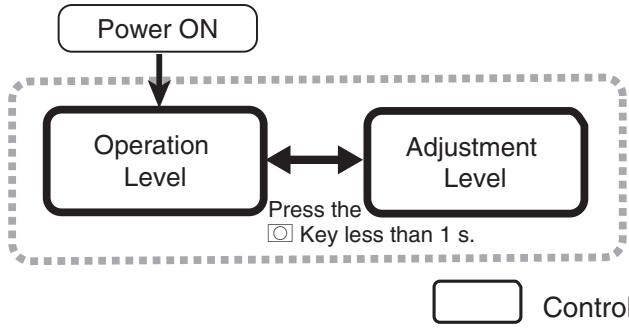
To move to the adjustment level from the operation level, press the Key once.
- The set points 0 to 3 in the adjustment level are the set values for switching the set point during multi-SP input.
- The following parameters are displayed for Controllers with CT Inputs: Heater current monitors, Leakage current monitors, heater burnout detections, HS alarms, and heater overcurrent detections.
- Adjustment level parameters can be changed after setting the Operation/ Adjustment Protect parameter to 0. Displays and changing levels are not possible if the Operation/Adjustment Protect parameter is set to 1 to 3. Protection is set in the protect level.
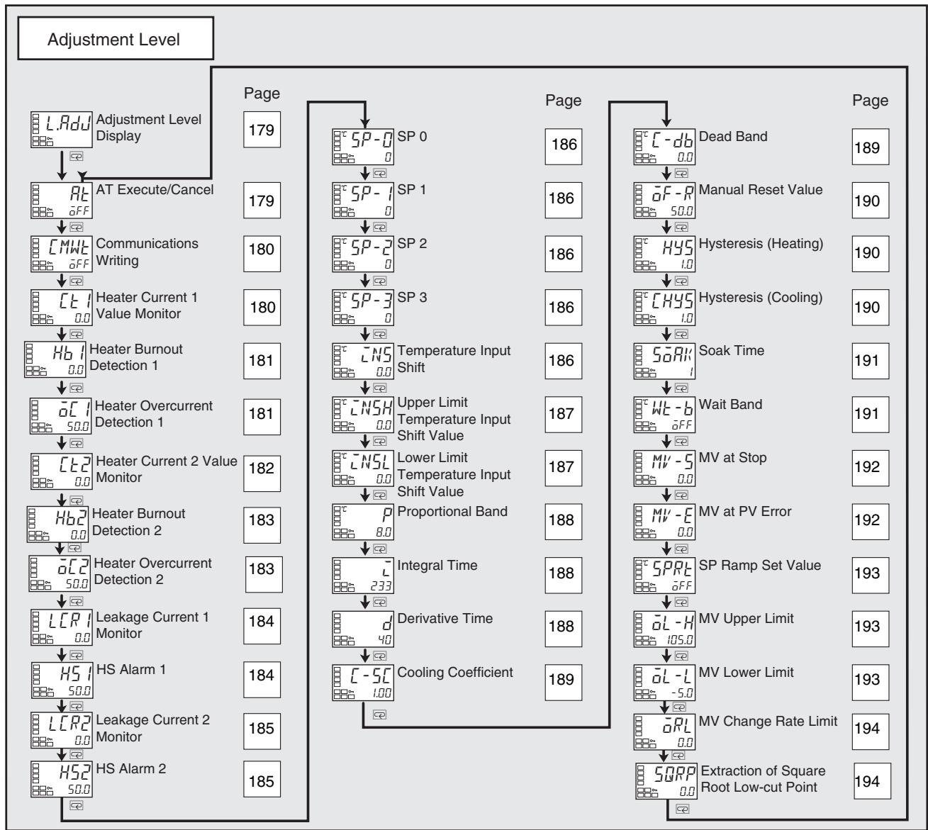
| L.RduJ | Adjustment Level Display | |
| Function | This parameter is displayed after moving to the adjustment level. When a logic operation is set, a period “.” will be displayed on the No. 2. display. · This parameter indicates that the adjustment level has been entered. (The Adjustment Level parameter will not be displayed again even if the Key is pressed in the adjustment level to scroll through the parameters.) | |
| Rt | AT Execute/Cancel | The ramp must be in operation, and 2-PID control must be used. Event Input Assignments 1 and 2 parameters must be other than 100% or 40% AT Execute/Cancel. |
| Function | This parameter executes auto-tuning (AT). · The MV is forcibly increased and decreased around the set point to find the characteristics of the control object. From the results, the PID constants are automatically set in the Proportional Band (P), Integral Time (I), and Derivative Time (D) parameters. · Both 100% AT and 40% AT are supported for AT. · Only 100% AT can be executed for heating and cooling control. · This parameter will not be displayed when either 100% or 40% AT execute/cancel is set to be executed using an event input. | |
| Operation | Setting rage | Default |
| OFF: AT Cancel AT-2: 100%AT Execute AT-1: 40%AT Execute | OFF | |
| · This parameter is normally OFF. Press the Key and select Rt -2 or Rt -1 to execute AT. AT cannot be executed when control is stopped or during ON/OFF control. · When AT execution ends, the parameter setting automatically returns to OFF. | ||
| See | ■ Related Parameters Proportional band, Integral time, Derivative time (adjustment level): Page 188 PID ON/OFF (initial setting level): Page 204 | |
| CMWE | Communications Writing | Communications must be supported. The Event Input Assignments 1 and 2 parameters must not be set to enable communications writing. |
| Function | ·This parameter enables/disables writing of parameters to the E5CN from the host (personal computer) using communications. ·This parameter is not displayed if communications write enable/disable is set for execution using an event input assignment 1 and 2. | |
| Setting | ON: Writing enabled OFF: Writing disabled ·Default: OFF | |
| See | ■ Related Parameters MB command logic switching (advanced function setting level): Page 229 Communications Unit No., Communications baud rate, Communications data length, Communications parity, Communications stop bits (communications setting level): Page 255 | |
| [Tab] | Heater Current 1 Value Monitor | Heater burnout, HS alarms, and heater overcurrent detection must be supported. Alarm 1 must be assigned. The HB ON/OFF parameter or Heater Overcurrent Use parameter must be set to ON. |
| Function | This parameter measures the heater current from the CT input used for detecting heater burnout. This parameter measures and displays the heater current value. ·Heater burnouts or heater overcurrent are not detected if the control out- put (heating) ON time is 100 ms or less. | |
| Monitor | Monitor range | Unit |
| 0.0 to 55.0 | A | |
| ·FFFF is displayed when 55.0 A is exceeded. ·If a heater burnout detection 1 or heater overcurrent detection 1 alarm is output, the HA indicator will light and the No. 1 display for the heater cur- rent 1 value monitor will flash. | ||
| See | ■ Related Parameters Heater burnout detection 1, Heater burnout detection 2 (adjustment level): Pages 181, and 183 HB ON/OFF (advanced function setting level): Page 222 Heater overcurrent detection 1, Heater overcurrent detection 2 (adjustment level): Pages 181, and 183 Heater overcurrent use (advanced function setting level): Page 246 Error displays [Tab]: Page 283 | |
| Hb I | Heater Burnout Detection 1 | Heater burnout, HS alarms, and heater overcurrent detection must be supported. Alarm 1 must be assigned. The HB ON/OFF parameter must be set to ON. | ||
| Function | This parameter sets the current for the heater burnout alarm to be output. · The heater burnout alarm is output when the heater current value falls below the setting of this parameter. · When the set value is 0.0, the heater burnout alarm output is turned OFF. When the set value is 50.0, the heater burnout alarm output is turned ON. | |||
| Setting | Setting range | Unit | Default | |
| 0.0 to 50.0 | A | 0.0 | ||
| See | ■ Related Parameters Heater current 1 value monitor (adjustment level): Page 180 Heater burnout detection, Heater burnout latch, Heater burnout hysteresis (advanced function setting level): Page 222 | |||
| aC I | Heater Overcurrent Detection 1 | Heater burnout, HS alarms, and heater overcurrent detection must be supported. Alarm 1 must be assigned. The Heater Overcurrent Use ON/OFF parameter must be set to ON. | ||
| Function | This parameter sets the current value for heater overcurrent alarm outputs. · A heater overcurrent alarm is output when the heater current exceeds the value set for this parameter. · When the set value is 50.0, the heater overcurrent alarm is turned OFF. When the set value is 0.0, the heater overcurrent alarm is turned ON. | |||
| Setting | Setting range | Unit | Default | |
| 0.0 to 50.0 | A | 50.0 | ||
| See | ■ Related Parameters Heater current 1 value monitor (adjustment level): Page 180 Heater overcurrent use, Heater overcurrent latch, Heater overcurrent hystere- | |||
| Heater Current 2 Value Monitor | Heater burnout, HS alarms, and heater overcurrent detection must be supported (two CTs). Alarm 1 must be assigned. The HB ON/OFF or Heater Overcurrent Use parameter must be set to ON. | |||
| Monitor range | Unit | |||
| 0.0 to 55.0 | A | |||
| ● FFFF is displayed when 55.0 A is exceeded. ● If a heater burnout detection 2 or heater overcurrent detection 2 alarm is output, the HA indicator will light and the No. 1 display for the heater cur- rent 2 value monitor will flash. | ||||
| ■ Related Parameters | ||||
| Heater burnout detection 1, Heater burnout detection 2 (adjustment level): Pages 181, and 183 | ||||
| HB ON/OFF (advanced function setting level): Page 222 | ||||
| Heater overcurrent detection 1, Heater overcurrent detection 2 (adjustment level): Pages 181, and 183 | ||||
| Heater overcurrent use (advanced function setting level): Page 246 | ||||
| Error Displays [E2]: Page 283 | ||||
| Hb2 | Heater Burnout Detection 2 | Heater burnout, HS alarms, and heater overcurrent detection must be supported (two CTs). Alarm 1 must be assigned. The HB ON/OFF parameter must be set to ON. | |
| Function | This parameter sets the current for the heater burnout alarm to be output. ·The heater burnout alarm is output when the heater current value falls below the setting of this parameter. ·When the set value is 0.0, the heater burnout alarm output is turned OFF. When the set value is 50.0, the heater burnout alarm output is turned ON. | ||
| Setting | Setting range | Unit | Default |
| 0.0 to 50.0 | A | 0.0 | |
| See | ■ Related Parameters Heater current 2 value monitor (adjustment level): Page 182 HB ON/OFF, Heater burnout latch, Heater burnout hysteresis (advanced function setting level): Page 222 | ||
| aC2 | Heater Overcurrent Detection 2 | Heater burnout, HS alarms, and heater overcurrent detection must be supported (two CTs). Alarm 1 must be assigned. The Heater Overcurrent Use parameter must be set to ON. | |
| Function | This parameter sets the current value for heater overcurrent alarm outputs. ·A heater overcurrent alarm is output when the heater current exceeds the value set for this parameter. ·When the set value is 50.0, the heater overcurrent alarm is turned OFF. When the set value is 0.0, the heater overcurrent alarm is turned turn ON. | ||
| Setting | Setting range | Unit | Default |
| 0.0 to 50.0 | A | 50.0 | |
| See | ■ Related Parameters Heater current 2 value monitor (adjustment level): Page 180 Heater overcurrent use, Heater overcurrent latch, Heater overcurrent hysteresis (advanced function setting level): Page 222 | ||
| LCRI | Leakage Current 1 Monitor | Heater burnout, HS alarms, and heater overcurrent detection must be supported. Alarm 1 must be assigned. The HS Alarm parameter must be set to ON. | |
| Function | This parameter measures the heater current from the CT input used for detecting SSR short-circuits. This parameter measures and displays the heater current when the heater is OFF. ·HS alarms are not detected if the control output (heating) OFF time is 100 ms or less. | ||
| Monitor | Monitor range | Unit | |
| 0.0 to 55.0 | A | ||
| See | ·FFFF is displayed when 55.0 A is exceeded. ·If an HS alarm 1 alarm is output, the HA indicator will light and the No. 1 display for the leakage current 1 monitor will flash. | ||
| ■ Related Parameters HS alarm 1, HS alarm 2 (adjustment level): Page 184 HS alarm use (advanced function setting level): Page 235 Error Displays LCR I: Page 283 | |||
| HS I | HS Alarm 1 | Heater burnout, HS alarms, and heater overcurrent detection must be supported. Alarm 1 must be assigned. The HS Alarm parameter must be set to ON. | |
| Function | This parameter sets the current for the HS alarm to be output. ·An HS alarm is output when the leakage current value exceeds the setting of this parameter. ·When the set value is 50.0, the HS alarm output is turned OFF. When the set value is 0.0, the HS alarm output is turned ON. | ||
| Setting | Setting range | Unit | Default |
| 0.0 to 50.0 | A | 50.0 | |
| See | ■ Related Parameters Leakage current 1 monitor (adjustment level): Page 184 HS alarm, HS alarm latch, HS alarm hysteresis (advanced function setting level): Page 235 | ||
| LCR2 | Leakage Current 2 Monitor | Heater burnout, HS alarms, and heater overcurrent detection must be supported (two CTs). Alarm 1 must be assigned. The HS Alarm parameter must be set to ON. | |
| Function | This parameter measures the heater current from the CT input used for detecting SSR short-circuits. This parameter measures and displays the heater current value. • HS alarms are not detected if the control output (heating) OFF time is 100 ms or less. | ||
| Monitor | Monitor range | Unit | |
| 0.0 to 55.0 | A | ||
| See | • FFFF is displayed when 55.0 A is exceeded. • If an HS alarm 2 alarm is output, the HA indicator will light and the No. 1 display for the leakage current 2 monitor will flash. | ||
| ■ Related Parameters HS alarm 1, HS alarm 2 (adjustment level): Page 184 HS alarm use (advanced function setting level): Page 235 Error Displays LCR2: Page 283 | |||
| HS2 | HS Alarm 2 | Heater burnout, HS alarms, and heater overcurrent detection must be supported (two CTs). Alarm 1 must be assigned. The HS Alarm parameter must be set to ON. | |
| Function | This parameter sets the current for the HS alarm to be output. • An HS alarm is output when the leakage current value exceeds the setting of this parameter. • When the set value is 50.0, the HS alarm output is turned OFF. When the set value is 0.0, the HS alarm output will turn ON. | ||
| Setting | Setting range | Unit | Default |
| 0.0 to 50.0 | A | 50.0 | |
| See | ■ Related Parameters Leakage current 2 monitor (adjustment level): Page 185 HS alarm use, HS alarm latch, HS alarm hysteresis (advanced function setting level): Page 235 | ||
| Setting range | Unit | Default |
| -199.9 to 999.9 | °C or °F | 0.0 |
| CN5H | Upper-limit Temperature Input Shift Value | The Input Type parameter must be set for a thermocouple or resistance thermometer and the Input Shift Type parameter must be set to a 2-point shift, or the Input Type parameter must be set for an infrared sensor. |
| CN5L | Lower-limit Temperature Input Shift Value |

These parameters are used to shift the input temperature at two points: an upper-limit temperature and a lower-limit temperature (as opposed to the Temperature Input Shift parameter, which shifts the input temperature by setting the shift for only one point). A 2-point shift enables more accurate offset of the input range compared with a 1-point shift if the input shift values at the upper and lower limits differ.
This parameter sets input shift values for the upper and lower limits (2-point shift) of the input range.
| Setting range | Unit | Default |
| -199.9 to 999.9 | °C or °F | 0.0 |
Related Parameters
Input type (initial setting level): Page 200
Input shift type (advanced function setting level): Page 233
| P | Proportional Band | The control must be set to 2-PID control. |
| L | Integral Time | |
| d | Derivative Time |
These parameters set PID control constants. PID constants are automatically set when AT or ST is executed.
P action: Refers to control in which the MV is proportional to the deviation (control error).
I action: Refers to a control action that is proportional to the time integral of the deviation. With proportional control, there is normally an offset (control error). Proportional action is thus used in combination with integral action. As time passes, this control error disappears, and the control temperature (process value) comes to agree with the set point.
D action: Refers to a control action that is proportional to the time derivative of the control error. The proportional control and integral control correct for errors in the control result, and thus the control system is late in responding to sudden changes in temperature. The derivative action increases the MV in proportion to the slope of the change in the temperature as a corrective action.
| Parameter name | Models | Setting range | Unit | Default | |
| Proportional Band | Controllers with Thermocouple/ Resistance Thermometer Multi- inputs | 0.1 to 999.9 | °C or °F (See note 1.) | 8.0 | |
| Controllers with Analog Inputs | %FS | 10.0 | |||
| Integral Time | 0 to 3999 | Second | 233 | ||
| Derivative Time | RT is OFF. | 0 to 3999 | Second | 40 | |
| RT is ON. | 0.0 to 999.9 | Second | 40.0 | ||
Note (1) Set "None" as the unit for Controllers with Analog Inputs.
(2) If the settings for RT (robust tuning) are changed, the proportional band (P), integral time (I), and derivative time (D) will be initiated.

Related Parameters
AT execute/cancel (adjustment level): Page 179
| Model | Setting range | Unit | Default | |||
| Controllers with Thermocouple/Resis- tance Thermometer Universal Inputs | -199.9 to 999.9 | °C or °F (See note.) | 0.0 | |||
| Controllers with Analog Inputs | -19.99 to 99.99 | %FS | 0.00 | |||
| Function | Note | Set “None” as the unit for Controllers with Analog Inputs. | ||||
| \(\mathsf{aF}-\mathsf{R}\) | Manual Reset Value | The control must be standard control and 2-PID control. The Integral Time parameter must be set to 0 . | ||||
| Setting range | Unit | Default | ||||
| 0.0 to 100.0 | % | 50.0 | ||||
| Function | ■ Related Parameters Integral time (adjustment level): Page 188 PID ON/OFF (initial setting level): Page 204 | |||||
| See | ||||||
| H45 | Hysteresis (Heating) | The control must be ON/OFF control. For the Hysteresis (Cooling) parame-ter, the control must be heating/cool-ing control. | ||||
| CH45 | Hysteresis (Cooling) | |||||
| Function | This parameter sets the hysteresis for ensuring stable operation at the ON/OFF switching point. · For standard control, use the Hysteresis (Heating) parameter. The Hysteresis (Cooling) parameter cannot be used. · For heating/cooling control, the hysteresis can be set independently for heating/cooling. The Hysteresis (Heating) parameter is used for the heat-ing side, and the Hysteresis (Cooling) parameter is used for the cooling side. | |||||
| Setting | Parameter name | Model | Setting range | Unit | Default | |
| Hysteresis (Heating) | Controllers with Thermocouple/Resistance Thermometer Universal Inputs | 0.1 to 999.9 | °C or °F (See note.) | 1.0 | ||
| Controllers with Analog Inputs | 0.01 to 99.99 | %FS | 0.10 | |||
| Hysteresis (Cooling) | Controllers with Thermocouple/Resistance Thermometer Universal Inputs | 0.1 to 999.9 | °C or °F (See note.) | 1.0 | ||
| Controllers with Analog Inputs | 0.01 o 99.99 | %FS | 0.10 | |||
Note Set "None" as the unit for Controllers with Analog Inputs.

Related Parameters
PID ON/OFF, Standard or heating/cooling (initial setting level): Page 204
| SoAK | Soak Time | The Program Pattern parameter must not be set to OFF. | |
| Function | ·This parameter sets the time for the control operation when using the sim- ple program function. | ||
| Setting range | Unit | Default | |
| 1 to 9999 | min or h | 1 | |
| See | ■ Related Parameters Program start, Soak time remain (operation level): Page 171 Wait band (adjustment level): Page 191 Program pattern (initial setting level): Page 205 Soak time unit (advanced function setting level): Page 243 | ||
| WT-b | Wait Band | The Program Pattern parameter must not be set to OFF. | |
| Function | ·This parameter sets the stable band within which the soak time is mea- sured for the simple program function. | ||
| Model | Setting range | Unit | |
| Controllers with Thermocouple/Resis- tance Thermometer Universal Inputs | OFF or 0.1 to 999.9 | °C or °F (See note.) | |
| Controllers with Analog Inputs | OFF or 0.01 to 99.99 | %FS | |
| Setting | Note | Set “None” as the unit for Controllers with Analog Inputs. | |
| See | ■ Related Parameters Program start, Soak time remain (operation level): Page 171 Soak time (adjustment level): Page 191 Program pattern (initial setting level): Page 205 Soak time unit (advanced function setting level): Page 243 | ||
| MV-5 | MV at Stop | The control must be set to 2-PID control. The MV at Stop and Error Addition parameter must be ON. | |
| Function | ·This parameter sets the MV to use when the RUN/STOP status changes from RUN to STOP. | ||
| Setting range | Unit | Default | |
| -5.0 to 105.0 for standard control -105.0 to 105.0 (heating/cooling control) | % | 0.0 | |
| See | ■ Related Parameters RUN/STOP (operation level): Page 172 MV at stop and error addition (advanced function setting level): Page 233 | ||
| MV-5 | MV at PV Error | The control must be set to 2-PID control. The MV at Stop and Error Addition parameter must be ON. | |
| Function | ·This parameter sets the MV to use when an input error occurs. | ||
| Setting range | Unit | Default | |
| -5.0 to 105.0 for standard control -105.0 to 105.0 (heating/cooling control) | % | 0.0 | |
| See | ■ Related Parameters MV at stop and error addition (advanced function setting level): Page 233 | ||
| SP Ramp Set Value | The ST parameter must be set to OFF. | |||
| Function | ·This parameter sets the rate of change during SP ramp operation. Set the maximum permissible change width per unit of time as the SP ramp set value. The SP ramp function is disabled if this parameter is set to OFF. ·During temperature input, the decimal point position of the SP ramp set value is dependent on the currently selected sensor, and during analog input it is dependent on scaling. | |||
| Setting | Setting range | Unit | Default | |
| OFF or 1 to 9999 | EU/s, EU/minute, or EU/h | aFF | ||
| See | ■ Related Parameters Input type: Page 200, Scaling upper limit, Scaling lower limit, Decimal point (initial setting level): Page 202, ST: Page 205 (initial setting level) SP ramp time unit (advanced function setting level): Page 220 | |||
| aL-H | MV Upper Limit | The control must be set to 2-PID control. | ||
| aL-L | MV Lower Limit | The ST parameter must be set to OFF. | ||
| Function | ·The MV Upper Limit and MV Lower Limit parameters set the upper and lower limits of the manipulated variable. When the calculated manipulated variable exceeds the upper or lower limit value, the upper or lower limit value will be the output level. ·MV Upper Limit The setting ranges during standard control and heating/cooling control are different. | |||
| Setting | Control method | Setting range | Unit | Default |
| Standard | MV lower limit + 0.1 to 105.0 | % | 105.0 | |
| Heating/cooling | 0.0 to 105.0 | |||
| See | ·MV Lower Limit The setting ranges during standard control and heating/cooling control are different. The manipulated variable for the cooling control output side during heating/cooling control is expressed as a negative value. | |||
| Control method | Setting range | Unit | Default | |
| Standard | -5.0 to MV upper limit - 0.1 | % | -5.0 | |
| Heating/cooling | -105.0 to 0.0 | -105.0 | ||
| Setting range | Unit | Default | ||
| 0.0 to 100.0 | % | 0.0 | ||

Related Parameters
Extraction of square root enable (initial setting level): Page 216
5-5 Monitor/Setting Item Level
Monitor/setting items can be displayed by means of the function key when the PF Setting parameter (advanced function setting level) is set to PFDP: Monitor/Setting Item (for the E5AN/EN only).

Monitor/Setting Item Display 1 to 5
The PF Setting parameter must be set to PFDP, and the Monitor/Setting Item 1 to 5 parameters must not be set to OFF.
Function
- When the PF Key is set to display monitor/setting items, pressing the PF Key will display in order the contents of the Monitor/Setting Item 1 to 5 parameters. The contents of these parameters are shown in the following table. For the setting (monitor) ranges, refer to the applicable parameters.
| Set value | Setting | Remarks | |
| Monitor/Setting | Symbol | ||
| 0 | Disabled | --- | |
| 1 | PV/SP/Multi-SP | Can be set. (SP) | --- |
| 2 | PV/SP/MV | Can be set. (SP) | --- |
| 3 | PV/SP /Soak time remain | Can be set. (SP) | --- |
| 4 | Proportional band (P) | Can be set. | P |
| 5 | Integral time (I) | Can be set. | L |
| 6 | Derivative time (D) | Can be set. | d |
| 7 | Alarm value 1 | Can be set. | RL - I |
| 8 | Alarm value upper limit 1 | Can be set. | RL IH |
| 9 | Alarm value lower limit 1 | Can be set. | RL IL |
| 10 | Alarm value 2 | Can be set. | RL - 2 |
| 11 | Alarm value upper limit 2 | Can be set. | RL 2H |
| 12 | Alarm value lower limit 2 | Can be set. | RL 2L |
| 13 | Alarm value 3 | Can be set. | RL - 3 |
| 14 | Alarm value upper limit 3 | Can be set. | RL 3H |
| 15 | Alarm value lower limit 3 | Can be set. | RL 3L |

Related Parameters
PF setting (advanced function setting level): Page 247
Monitor/setting items 1 to 5 (advanced function setting level): Page 248
5-6 Manual Control Level
The manipulated variable can be set in manual mode while the PV/MV parameter is displayed.
The final MV used in automatic mode will be used as the initial manual MV when moving from automatic mode to manual mode. In manual mode, the change value will be saved immediately and reflected in the actual MV.
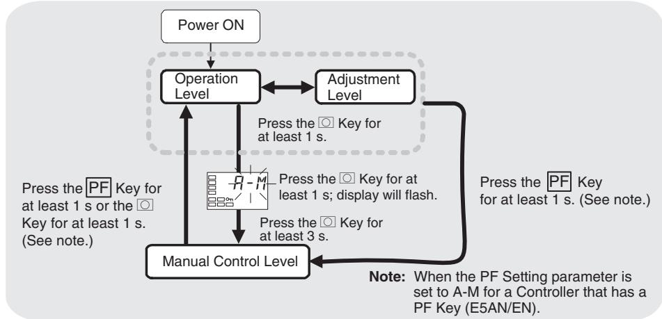
To move from the operation level to the manual control level, press the Key for at least three seconds with the Auto/Manual Switch parameter displayed. In addition, this operation can be performed using the PF Key by setting the PF Key parameter (advanced function setting level) to A-M (Auto/Manual). For details on the setting method, refer to 4-13 Performing Manual Control.
This setting cannot be made during ON/OFF operation.
- The MANU indicator will light during manual control.
- It is not possible to move to any displays except for the PV/MV parameter during manual operation.
- To return to the operation level, press the Key or the PF Key in the manual control level for at least one second.
PV/MV (Manual MV)

Function
The manual control level display appears as shown below.
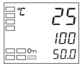
With No. 3 Display
PV/SP/Manual MV
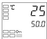
PV/Manual MV
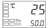
Without No. 3 Display
PV/Manual MV
Note: When the PV/SP Display Screen
Selection parameter is 0.
| Monitor range | Unit | ||
| Process value | Temperature: According to indication range for each sensor. Analog: Scaling lower limit -5% FS to Scaling upper limit +5% FS (Refer to page 303.) | EU | |
| Set point | SP lower limit to SP upper limit | EU | |
| Setting range | Unit | ||
| MV (manual MV) | Standard control | -5.0 to 105.0 (See note.) | % |
| Heating/cooling control | -105.0 to 105.0 (See note.) | ||
Note When the Manual MV Limit Enable parameter is set to ON, the setting range will be the MV lower limit to the MV upper limit.

Related Parameters
Standard or heating/cooling (initial setting level): Page 204
5-7 Initial Setting Level
This level is used to set up the basic Temperature Controller specifications. In this level, you can set the Input Type parameter to set the sensor input to be connected, limit the setting range of set points, set the alarm modes, and perform other operations.
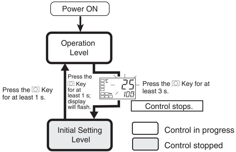
To move from the operation level to the initial setting level, press the Key for at least three seconds with any parameter displayed except for the Auto/ Manual Switch parameter.
- The initial setting level is not displayed when the Initial Setting/Communications Protect parameter is set to 2. It can be used when the Initial Setting/Communications Protect parameter is set to 0 or 1.
- If the Input Type parameter is set for an analog input, the following parameters will be set: Scaling upper limit, Scaling lower limit, and Decimal point.
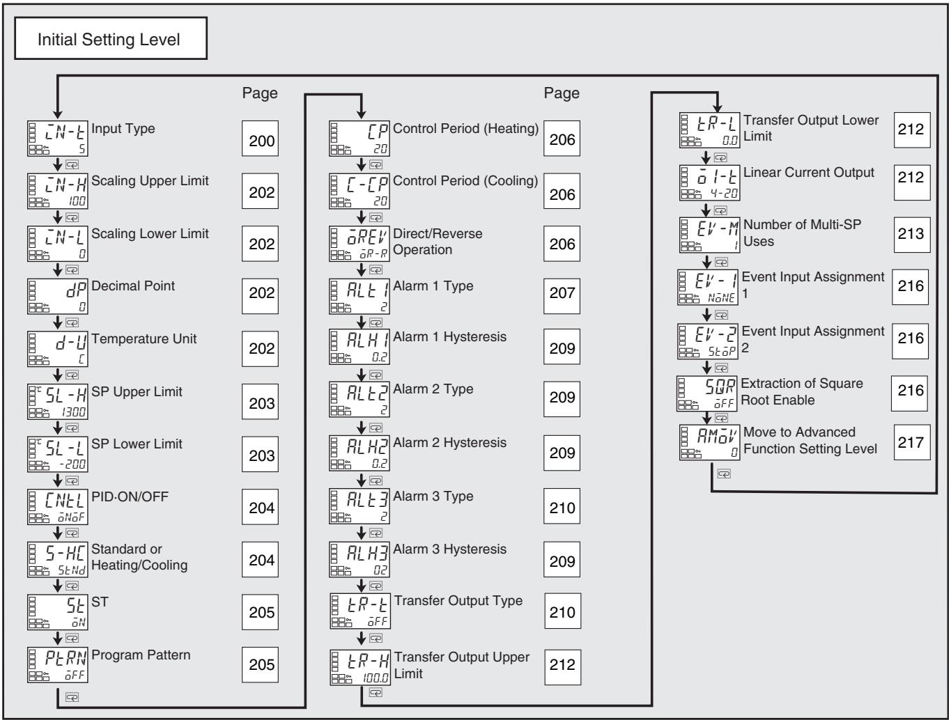
[\left\lbrack {N - t}\right\rbrack ]
Input Type
Function
Setting
- This parameter sets the type of sensor.
- When this parameter is changed, the set point limiter is changed to the defaults. If the limiter must be specified, set the SP Upper Limit and SP Lower Limit parameters (initial setting level) again.
- Set one of the set values from the following table. The defaults are as follows:
- Controllers with Thermocouple/Resistance Thermometer Universal Inputs: 5 (K thermocouple)
- Controllers with Analog Inputs: 0 (current input, 4 to 20 mA)
- If a platinum resistance thermometer is mistakenly connected while a setting for other than a platinum resistance thermometer is in effect, S.ErrR will be displayed. To clear the S.ErrR display, check the wiring and then cycle the power.
| Input type | Specifications | Set value | Input temperature range | |
| Controllers with Ther-mocouple/ResistanceThermometer Multi-inputs | Platinum resistance thermometer | Pt100 | 0 | -200 to 850 (°C)/-300 to 1,500 (°F) |
| 1 | -199.9 to 500.0 (°C)/-199.9 to 900.0 (°F) | |||
| 2 | 0.0 to 100.0 (°C)/0.0 to 210.0 (°F) | |||
| JPt100 | 3 | -199.9 to 500.0 (°C)/-199.9 to 900.0 (°F) | ||
| 4 | 0.0 to 100.0 (°C)/0.0 to 210.0 (°F) | |||
| Thermocouple | K | 5 | -200 to 1,300 (°C)/-300 to 2,300 (°F) | |
| 6 | -20.0 to 500.0 (°C)/0.0 to 900.0 (°F) | |||
| J | 7 | -100 to 850 (°C)/-100 to 1,500 (°F) | ||
| 8 | -20.0 to 400.0 (°C)/0.0 to 750.0 (°F) | |||
| T | 9 | -200 to 400 (°C)/-300 to 700 (°F) | ||
| 10 | -199.9 to 400.0 (°C)/-199.9 to 700.0 (°F) | |||
| E | 11 | -200 to 600 (°C)/-300 to 1,100 (°F) | ||
| L | 12 | -100 to 850 (°C)/-100 to 1,500 (°F) | ||
| U | 13 | -200 to 400 (°C)/-300 to 700 (°F) | ||
| 14 | -199.9 to 400.0 (°C)/-199.9 to 700.0 (°F) | |||
| N | 15 | -200 to 1,300 (°C)/-300 to 2,300 (°F) | ||
| R | 16 | 0 to 1,700 (°C)/0 to 3,000 (°F) | ||
| S | 17 | 0 to 1,700 (°C)/0 to 3,000 (°F) | ||
| B | 18 | 100 to 1,800 (°C)/300 to 3,200 (°F) | ||
| Infrared Temperature Sensor ES1B | 10 to 70 (°C) | 19 | 0 to 90 (°C)/0 to 190 (°F) | |
| 60 to 120 (°C) | 20 | 0 to 120 (°C)/0 to 240 (°F) | ||
| 115 to 165 (°C) | 21 | 0 to 165 (°C)/0 to 320 (°F) | ||
| 140 to 260 (°C) | 22 | 0 to 260 (°C)/0 to 500 (°F) | ||
| Analog input | 0 to 50 mV | 23 | One of the following ranges depending on the scaling.-1,999 to 9,999-199.9 to 999.9 | |
| Thermocouple | W | 24 | 0 to 2,300 (°C)/0 to 3,200 (°F) | |
| PLII | 25 | 0 to 1,300 (°C)/0 to 2,300 (°F) |
| Input type | Specifications | Set value | Input temperature range | |
| Controllers with Ana-log Inputs | Current input | 4 to 20 mA | 0 | One of the following ranges depending on the scaling. -1,999 to 9,999 |
| 0 to 20 mA | 1 | |||
| Voltage input | 1 to 5 V | 2 | -199.9 to 999.9 | |
| 0 to 5 V | 3 | -19.99 to 99.99 | ||
| 0 to 10 V | 4 | -1.999 to 9.999 |

Related Parameters
Temperature unit, Set point upper limit, Set point lower limit (initial setting level): Page 202
| Parameter name | Setting range | Unit | Default |
| Scaling Upper Limit | Scaling lower limit + 1 to 9999 | None | 100 |
| Scaling Lower Limit | -1999 to scaling upper limit - 1 | None | 0 |
| 2 | 2 digits past decimal point | 12.34 | |
| 3 | 3 digits past decimal point | 1.234 |
d-U
Temperature Unit
The input type must be set for a temperature input.
Function
- Set the temperature input unit to either ^ C or ^ F .
Setting

| Setting range | Default |
| E: °C, F: °F | E |
Related Parameters
Input type (initial setting level): Page 200
[{5L} - H]
[{5L} - L]
SP Upper Limit
SP Lower Limit
Function
- These parameters set the upper and lower limits of the set points. A set point can be set within the range defined by the upper and lower limit set values in the SP Upper Limit and SP Lower Limit parameters. If these parameters are reset, any set point that is outside of the new range will be forcibly changed to either the upper limit or the lower limit.
- When the temperature input type and temperature unit have been changed, the set point upper limit and set point lower limit are forcibly changed to the upper and lower limits of the sensor.
- During temperature input, the decimal point position depends on the currently selected sensor, and during analog input it depends on the Decimal Point parameter setting.
Setting
Controllers with Thermocouple/Resistance Thermometer Universal Inputs
| Parameter name | Setting range | Unit | Default | |
| Set Point Upper Limit | Temperature | SP lower limit + 1 to Input setting range upper limit | EU | 1300 |
| Analog | SP lower limit + 1 to scaling upper limit | EU | 100 | |
| Set Point Lower Limit | Temperature | Input setting range lower limit to SP upper limit - 1 | EU | -200 |
| Analog | Scaling lower limit to SP upper limit - 1 | EU | 0 |
Controllers with Analog Inputs
| Parameter name | Setting range | Unit | Default |
| Set Point Upper Limit | SP lower limit + 1 to scaling upper limit | EU | 100 |
| Set Point Lower Limit | Scaling lower limit to SP upper limit - 1 | EU | 0 |

Related Parameters
Input type: Page 200, Temperature unit: Page 202 (initial setting level)
| Cnel | PID ON/OFF | |
| Function | This parameter selects 2-PID control or ON/OFF control. The auto-tuning and self-tuning functions can be used in 2-PID control. | |
| Setting range | Default | |
| Pd: 2-PID, Nof: ON/OFF | aNof | |
| ■ Related Parameters AT execute/cancel: Page 179, Manual reset value, Hysteresis (heating), and Hysteresis (cooling): Page 190 (adjustment level) ST stable range (advanced function setting level): Page 224 | ||
| 5-HC | Standard or Heating/Cooling | |
| Function | This parameter selects standard control or heating/cooling control. When heating/cooling control is selected for the E5CN or E5CN-U, the auxiliary output 2 terminal (SUB2) is assigned as the control output (coo- ing). When heating/cooling control is selected for the E5AN or E5EN, the auxi- lary output 3 terminal (SUB3) is assigned as the control output (cooling). When heating/cooling control is selected for the E5GN, the auxiliary out- put 1 terminal (SUB1) is assigned as the control output (cooling). If standard control is selected, set the Control Output 1 Assignment to a (con- trol output (heating)) for either direct (cooling) or reverse (heating) operation. | |
| Setting | Default | |
| 5Nd: Standard, H-C: Heating/cooling | 5Nd | |
| ■ Related Parameters MV monitor (heating): Page 175, MV monitor (cooling): Page 176 (operation level) Cooling coefficient, Dead band: Page 189, Hysteresis (heating), Hysteresis (cooling): Page 190 (adjustment level) Control period (heat), Control period (cool) (initial setting level): Page 206 Control output 1 assignment: Page 238, Control output 2 assignment, Auxi- lary output 1 assignment: Page 240, Auxiliary output 2 assignment: Page 241, Auxiliary output 3 assignment: Page 242 (advanced function setting level) | ||
| ST (self-tuning) | The control must be set to a temper- ature input, standard control, and 2- PID control. | |||
| Function | The ST (self-tuning) function executes tuning from the start of program execution to calculate PID constants matched to the control target. When the ST function is in operation, be sure to turn ON the power supply of the load connected to the control output simultaneously with or before starting Controller operation. • Auto-tuning can be started during self-tuning. | |||
| Parameter name | Setting range | Unit | Default | |
| ST | aFF: ST function OFF, aN: ST function ON | None | aN | |
| See | ■ Related Parameters Input type: Page 200, PID ON/OFF: Page 204 (initial setting level), ST stable range (advanced function setting level): Page 224 | |||
| PERN | Program Pattern | |||
| Function | This parameter sets the type of control when using the simple program func- tion. • If the program pattern is set to aFF, the simple program will not operate. • If the program pattern is set to 5EaP, the RUN/STOP status will change to STOP after the soak time has expired. If the program pattern is set to cANe, control will continue in RUN status after the soak time has expired. | |||
| Setting | Setting range | Default | ||
| aFF | Simple program function turned OFF | aFF | ||
| 5eap | Go to STOP mode at end of program. | |||
| cANe | Continue in RUN mode at end of program. | |||
| See | ■ Related Parameters Program start, Soak time remain: Page 171, RUN/STOP: Page 172 (operation level) Soak time, Wait band (adjustment level): Page 191 Soak time unit (advanced function setting level): Page 243 | |||
| Control Period (Heating) | The cooling control output and heating control output must be assigned to relay or voltage outputs (for driving SSR). | |||
| Control Period (Cooling) | The control must be set to 2-PID control. | |||
| Function | Control Period (Cooling) | For the Control Period (Cooling) parameter, the control must be set to heating/cooling control. | ||
| Setting | These parameters set the output periods. Set the control periods taking the control characteristics and the electrical durability of the relay into consideration. For standard control, use the Control Period (Heating) parameter. The Control Period (Cooling) parameter cannot be used. When the heating control output is a current output, the Control Period (Heating) parameter cannot be used. For heating/cooling control, the control period can be set independently for heating and cooling. The Control Period (Heating) parameter is used for the heating control output, and the Control Period (Cooling) parameter is used for the cooling control output | |||
| Parameter name | Setting range | Unit | Default | |
| Control Period (Heating) | 0.5 or 1 to 99 | Second | 20 | |
| Control Period (Cooling) | 0.5 or 1 to 99 | Second | 20 | |
| See | ■ Related Parameters PID ON/OFF (initial setting level): Page 204 | |||
| aREV | Direct/Reverse Operation | |||
| Function | “Direct operation” refers to control where the manipulated variable is increased when the process value increases. Alternatively, “reverse operation” refers to control where the manipulated variable is increased when the process value decreases. | |||
| Setting | Setting range | Default | ||
| aR-R: Reverse operation, aR-d: Direct operation | aR-R | |||
ALTE
Alarm 1 Type
Alarm 1 must be assigned.
- Select one of the following alarm 1 types:
Deviation, deviation range, absolute value, LBA, or PV change rate alarm.
| Set value | Alarm type | Alarm output operation | Description of function | |
| When alarm value X is positive | When alarm value X is negative | |||
| 0 | Alarm function OFF | Output OFF | No alarm | |
| 1 (See note 1.) | Upper- and lower-limit | ONOFFSP | See note 2. | Set the deviation in the set point by setting the alarm upper limit (H) and alarm lower limit (L). |
| 2 | Upper-limit | ONOFFSP | ONOFFSP | Set the upward deviation in the set point by setting the alarm value (X). |
| 3 | Lower-limit | ONOFFSP | ONOFFSP | Set the downward deviation in the set point by setting the alarm value (X). |
| 4 (See note 1.) | Upper- and lower-limit range | ONOFFSP | See note 3. | Set the deviation in the set point by setting the alarm upper limit (H) and alarm lower limit (L). |
| 5 (See note 1.) | Upper- and lower-limit with standby sequence | ONOFFSPSee note 5. | See note 4. | A standby sequence is added to the upper- and lower-limit alarm (1). (See note 6.) |
| 6 | Upper-limit with standby sequence | ONOFFSP | ONOFFSP | A standby sequence is added to the upper-limit alarm (2). (See note 6.) |
| 7 | Lower-limit with standby sequence | ONOFFSP | ONOFFSP | A standby sequence is added to the lower-limit alarm (3). (See note 6.) |
| 8 | Absolute-value upper-limit | ONOFF0 | ONOFF0 | The alarm will turn ON if the process value is larger than the alarm value (X) regardless of the set point. |
| 9 | Absolute-value lower-limit | ONOFF0 | ONOFF0 | The alarm will turn ON if the process value is smaller than the alarm value (X) regardless of the set point. |
| 10 | Absolute-value upper-limit with standby sequence | ONOFF0 | ONOFF0 | A standby sequence is added to the absolute-value upper-limit alarm (8). (See note 6.) |
| 11 | Absolute-value lower-limit with standby sequence | ONOFF0 | ONOFF0 | A standby sequence is added to the absolute-value lower-limit alarm (9). (See note 6.) |
| 12 | LBA (alarm 1 type only) | --- | Refer to page 118. (See note 7.) | |
| 13 | PV change rate alarm | --- | Refer to page 72. (See note 8.) | |
Note
(1) With set values 1, 4 and 5, the upper- and lower- limit values can be set independently for each alarm type, and are expressed as “L” and “H.”
(2) Set value: 1 (Upper- and lower-limit alarm)
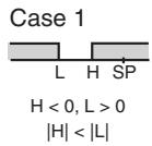
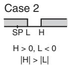
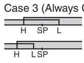
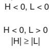
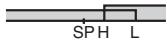

(3) Set value: 4 (Lower limit range)
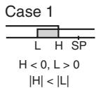
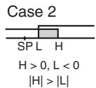
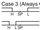

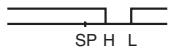

(4) Set value: 5 (Upper- and lower-limit with standby sequence)
- For the lower-limit alarms in cases 1 and 2 above, the alarm is normally OFF if upper- and lower-limit hysteresis overlaps.
- In case 3, the alarm is always OFF.
(5) Set value: 5 (The alarm is always OFF if upper- and lower-limit alarm hysteresis with standby sequence overlaps.)
(6) Refer to 4-2-1 Standby Sequence for information on the operation of the standby sequence.
(7) Refer to 4-12-1 Loop Burnout Alarm (LBA)
(8) Refer to PV Change Rate Alarm on page 72.
- Set the alarm type independently for each alarm in the Alarm 1 to 3 Type parameters in the initial setting level. The default is 2 (Upper-limit alarm).
Related Parameters
Alarm value 1: Page 172, Alarm value upper limit 1, Alarm value lower limit 1: Page 174 (operation level)
Standby sequence reset: Page 221, Auxiliary output 1 open in alarm: Page 222, Alarm 1 latch: Page 227 (advanced function setting level), Alarm 1 hysteresis: Page 209 (initial setting level)

| RLH1 | Alarm 1 Hysteresis | Alarm 1 must be assigned. The alarm 1 type must not be 0, 12, or 13. |
| RLH2 | Alarm 2 Hysteresis | Alarm 2 must be assigned. The alarm 2 type must not be 0, 12, or 13. |
| RLH3 | Alarm 3 Hysteresis | Alarm 3 must be assigned. The alarm 3 type must not be 0, 12, or 13. |
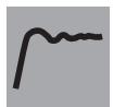
Function
These parameters set the hysteresis for alarms 1, 2, and 3.
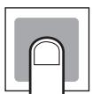
Setting
| Models | Setting range | Unit | Default |
| Model with thermocouple/resistance thermometer universal input | 0.1 to 999.9 | °C or °F (See note.) | 0.2 |
| Model with analog Input | 0.01 to 99.99 | %FS | 0.02 |
Note Set "None" as the unit for analog inputs.

Related Parameters
Alarm value 1 to 3: Page 173, Alarm value upper limit 1 to 3, Alarm value lower limit 1 to 3: Page 174 (operation level)
Alarm 1 to 3 type (initial setting level): Pages 207 to 210
Standby sequence reset: Page 221, Auxiliary output 1 to 3 open in alarm: Page 222, Alarm 1 to 3 latch: Page 227 (advanced function setting level)
ALTE
Alarm 2 Type
Alarm 2 must be assigned.
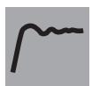
Function
- Select one of the following four alarm 2 types: Deviation, deviation range, absolute value, or PV change rate alarm.

Setting
Refer to the alarm 1 type list. The 12: LBA (Loop Burnout Alarm) setting in that list cannot be used.

Related Parameters
Alarm value 2: Page 173, Alarm value upper limit 2, Alarm value lower limit 2: Page 174 (operation level)
Standby sequence reset: Page 221, Auxiliary output * open in alarm: Page 222, Alarm 2 hysteresis: Page 209, Alarm 2 latch: Page 227 (advanced function setting level)
| RL-3 | Alarm 3 Type | Alarm 3 must be assigned. |
| Function | ·Select one of the following four alarm 3 types: Deviation, deviation range, absolute value, or PV change rate alarm. | |
| Setting | Refer to the alarm 1 type list. The 12: LBA (Loop Burnout Alarm) setting in that list cannot be used. | |
| See | ■ Related Parameters Alarm value 3: Page 173, Alarm value upper limit 3, Alarm value lower limit 3: Page 175 (operation level) Standby sequence reset: Page 221, Auxiliary output * open in alarm: Page 222, Alarm 3 hysteresis: Page 209, Alarm 3 latch: Page 227 (advanced func-tion setting level) | |
| ER-3 | Transfer Output Type | There must be a transfer output or a current output. |
- This parameter sets the transfer output type.
- The operation is shown in the following table.
Transfer Output Destination
| Control output 1 | Control output 2 | Transfer output destination |
| Current output | • No • Relay output • Voltage output (for driving SSR) | Control output 1 |
| • Relay output • Voltage output (for driving SSR) | • No • Relay output • Voltage output (for driving SSR) | No |
■ Precision and User Calibration
| Precision | User calibration | |
| Transfer output | ±0.3% FS | Supported (See note.) |
| Simple transfer output | ±0.3% FS | Not supported. |
Note Refer to SECTION 6 CALIBRATION for details on the calibration procedure.
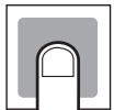
Setting
| Transfer output type | Default | |
| OFF | OFF | OFF |
| Set point | SP | |
| Set point during SP ramp | SP-M | |
| PV | PV | |
| MV monitor (heating) | MV | |
| MV monitor (cooling) | [-MV] | |

Related Parameter
Transfer output upper limit, Transfer output lower limit (initial setting level): Page 212
E-R-H
LR-L
Transfer Output Upper Limit
Transfer Output Lower Limit
There must be a transfer output or a current output.
The transfer output type must not be set to OFF.
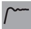
Function
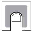
Setting
- This parameter sets the upper and lower limit values of transfer outputs.
| Transfer output type | Setting range | Default | Unit | ||
| Transfer output lower limit | Transfer output upper limit | ||||
| Set point | SP lower limit to SP upper limit | SP lower limit | SP upper limit | EU | |
| Set point during SP ramp | SP lower limit to SP upper limit | ||||
| PV | Temperature | Input setting range lower limit to input setting range upper limit | Input setting range lower limit | Input setting range upper limit | |
| Analog | Analog scaling lower limit to analog scaling upper limit | Scaling lower limit | Scaling upper limit | ||
| MV monitor (heating) | Standard | -5.0 to 105.0 | 0.0 | 100.0 | % |
| Heating/ cooling | 0.0 to 105.0 | ||||
| MV monitor (cooling) | 0.0 to 105.0 | ||||
See
Related Parameter
Transfer output type (initial setting level): Page 210
a1-t
Linear Current Output
Control output 1 must be a current output.
This parameter selects the output type for linear current outputs.
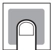
Setting
| Linear current output | Default |
| 4-20: 4 to 20 mA | 4-20 |
| 0-20: 0 to 20 mA |
Note Even when control output 1 is used as a control output or a simple transfer output, 0 to 20mA can be used.
See
Related Parameter
Transfer output type (initial setting level): Page 210
E-V-M
Number of Multi-SP Uses
An event input must be assigned.
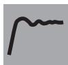
Function
- Multi-SP is a function for setting set points 0 to 3 in advance, and switching between these set points using a combination of event input ON/OFF signals.
- The Number of Multi-SP Uses parameter is used to switch between using two and four preset set points.
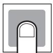
Setting
| Setting range | Default |
| 0 to 2 | 1 |
- Whether the Event Input Assignments 1 and 2 parameters are displayed or hidden is determined by the Number of Multi-SP Uses parameter setting.
Models with Two Event Inputs, 1 and 2
| Event input assignment 1 | Event input assignment 2 | Description of EV1 and EV2 operation | ||
| Number of multi-SP uses | 0 | Displayed (Multi-SP not used). | EV1 and EV2 will perform the operation command assigned using the Event Input Assignment 1 and 2 parameters. | |
| 1 | Not displayed (Operation performed with two Multi-SP points.) | Displayed (Event input 2 not used as multi-SP switch). | EV1 will be used for the Multi-SP function to switch between set points 0 and 1. EV2 will perform the operation command assigned using the Event Input Assignment 2 parameter. | |
| 2 | Not displayed (Operation performed with four Multi-SP points.) | EV1 and EV2 will be used for the Multi-SP function to switch between set points 0, 1, 2, and 3. | ||
The following tables show the relationships between ON/OFF combinations of event inputs 1 and 2 and selected set points.
Number of Multi-SP Uses: 1:
| Even input 1 | Selected set point |
| OFF | Set point 0 |
| ON | Set point 1 |
Number of Multi-SP Uses: 2
| Even input 1 | Even input 2 | Selected set point |
| OFF | OFF | Set point 0 |
| ON | OFF | Set point 1 |
| OFF | ON | Set point 2 |
| ON | ON | Set point 3 |
Models with Two Event Inputs, 3 and 4
| Event input assignment 3 | Event input assignment 4 | Description of EV3 and EV4 operation | ||
| Number of multi-SP uses | 0 | Displayed (Multi-SP not used). | EV3 and EV4 will perform the operation command assigned using the Event Input Assign-ment 3 and 4 parameters. | |
| 1 | Not displayed (Operation per-formed with two Multi-SP points.) | Displayed (Event input 4 not used as multi-SP switch). | EV3 will be used for the Multi-SP function to switch between set points 0 and 1. EV4 will perform the operation com-mand assigned using the Event Input Assignment 4 parameter. | |
| 2 | Not displayed (Operation performed with four Multi-SP points.) | EV3 and EV4 will be used for the Multi-SP function to switch between set points 0, 1, 2, and 3. | ||
The following tables show the relationships between ON/OFF combinations of event inputs 3 and 4 and selected set points.
Number of Multi-SP Uses: 1:
| Even input 3 | Selected set point |
| OFF | Set point 0 |
| ON | Set point 1 |
Number of Multi-SP Uses: 2
| Even input 3 | Even input 4 | Selected set point |
| OFF | OFF | Set point 0 |
| ON | OFF | Set point 1 |
| OFF | ON | Set point 2 |
| ON | ON | Set point 3 |
Models with Four Event Inputs, 1 to 4
| Event input assignment 1 | Event input assignment 2 | Event input assignment 3 | Event input assignment 4 | Description of EV1, EV2, EV3, and EV4 operation | ||
| Number of Multi-SP Uses | 0 | Displayed (Multi-SP not used). | EV1, EV2, EV3, and EV4 will perform the operation command assigned using the Event Input Assignment 1, 2, 3, and 4 parameters. | |||
| 1 | Not displayed (Operation performed with two Multi-SP points.) | Displayed (Event inputs 2, 3, and 4 cannot be used for multi-SP switching.) | EV1 will be used for the Multi-SP function to switch between set points 0 and 1. EV2, EV3, and EV4 will perform the operation command assigned using the Event Input Assignment 2, 3, and 4 parameters. | |||
| 2 | Not displayed (Operation performed with four Multi-SP points.) | Displayed (Event inputs 3 and 4 cannot be used for multi-SP switching.) | EV1 and EV2 will be used for the Multi-SP function to switch between set points 0, 1, 2, and 3. EV3 and EV4 will perform the operation command assigned using the Event Input Assignment 3 and 4 parameters. | |||
Only event inputs 1 and 2 are used for the multi-SP function.
The following tables show the relationships between ON/OFF combinations of event inputs 1 and 2 and selected set points.
Number of Multi-SP Uses: 1:
| Even input 1 | Selected set point |
| OFF | Set point 0 |
| ON | Set point 1 |
Number of Multi-SP Uses: 2
| Even input 1 | Even input 2 | Selected set point |
| OFF | OFF | Set point 0 |
| ON | OFF | Set point 1 |
| OFF | ON | Set point 2 |
| ON | ON | Set point 3 |
- The following table shows the functions assigned when an Event Input Assignment (1 or 2) is displayed.
| Setting | Function |
| None | None |
| STOP | RUN/STOP |
| MANU | Auto/Manual Switch |
| PRST | Program start (See note 1.) |
| dRS | Invert Direct/Reverse Operation |
| RE -2 | 100% AT Execute/Cancel |
| RE -1 | 40% AT Execute/Cancel (See note 2.) |
| WEPE | Setting Change Enable/Disable |
| LRE | Alarm Latch Cancel |
Note
(1) PRST (Program Start) can be set even when the Program Pattern parameter is set to OFF, but the function will be disabled.
(2) This function can be set for heating/cooling control, but the function will be disabled.
- When any of the following functions is set for an Event Input Assignment parameter, the same function cannot be set for another Event Input Assignment parameter: STOP (RUN/STOP), MANU (Auto/Manual Switch), PRST (Program Start), DRS (Invert Direct/Reverse Operation), AT-2 (100% AT Execute/Cancel), AT-1 (40% AT Execute/Cancel), WTPT (Setting Change Enable/Disable), or LAT (Alarm Latch Cancel).
Note
Event inputs can be used on the E5CN-□M□ (with an E53-CN□B□N2) or E5AN/EN-□M□-N (with an E53-AKB) Controllers. Turn event inputs ON and OFF while the power is being supplied. Event input ON/OFF changes are detected for inputs of 50 ms or longer.
See
Related Parameter
SP0 to SP3 (adjustment level): Page 186
Event input assignment 1 and 2: Page 216 (initial setting level), Multi-SP use: Page 220 (advanced function setting level)
| Setting | Function |
| N0NE | None |
| SToP | RUN/STOP |
| MANU | Auto/Manual |
| PRSt | Program start (See note 1.) |
| dRS | Invert Direct/Reverse Operation |
| Rt-2 | 100% AT Execute/Cancel |
| Rt-1 | 40% AT Execute/Cancel (See note 2.) |
| WEPl | Setting Change Enable/Disable |
| LRT | Alarm Latch Cancel |
5QR
Extraction of Square Root Enable
An analog input must be supported.
This parameter enables and disables square root extraction.
| Setting range | Default |
| aN: Enabled, aFF: Disabled | OFF |
| See | ■ Related Parameter Extraction of square root low-cut point (adjustment level): Page 194 |
| RMol' | Move to Advanced Function Setting Level The Initial Setting/Communications Protect parameter must be set to 0. |
| Function | · Set the Move to Advanced Function Setting Level parameter set value to “-169.” · Move to the advanced function setting level either by pressing Key or Key or by waiting or two seconds to elapse. |
| See | ■ Related Parameter Initial setting/communication protect (protect level): Page 160 |
5-8 Advanced Function Setting Level
The advanced function setting level is used for optimizing Controller performance. To move to this level, input the password ("-169") from the initial setting level.
To be able to enter the password, the Initial Setting/Communications Protect parameter in the protect level must be set to 0.
- The parameters in this level can be used when the Initial Setting/Communications Protect parameter is set to 0.
- To switch between setting levels, press the .
- To change set values, press the and Keys.
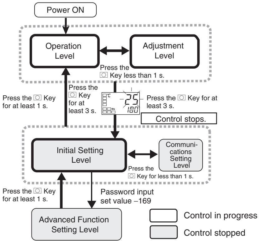
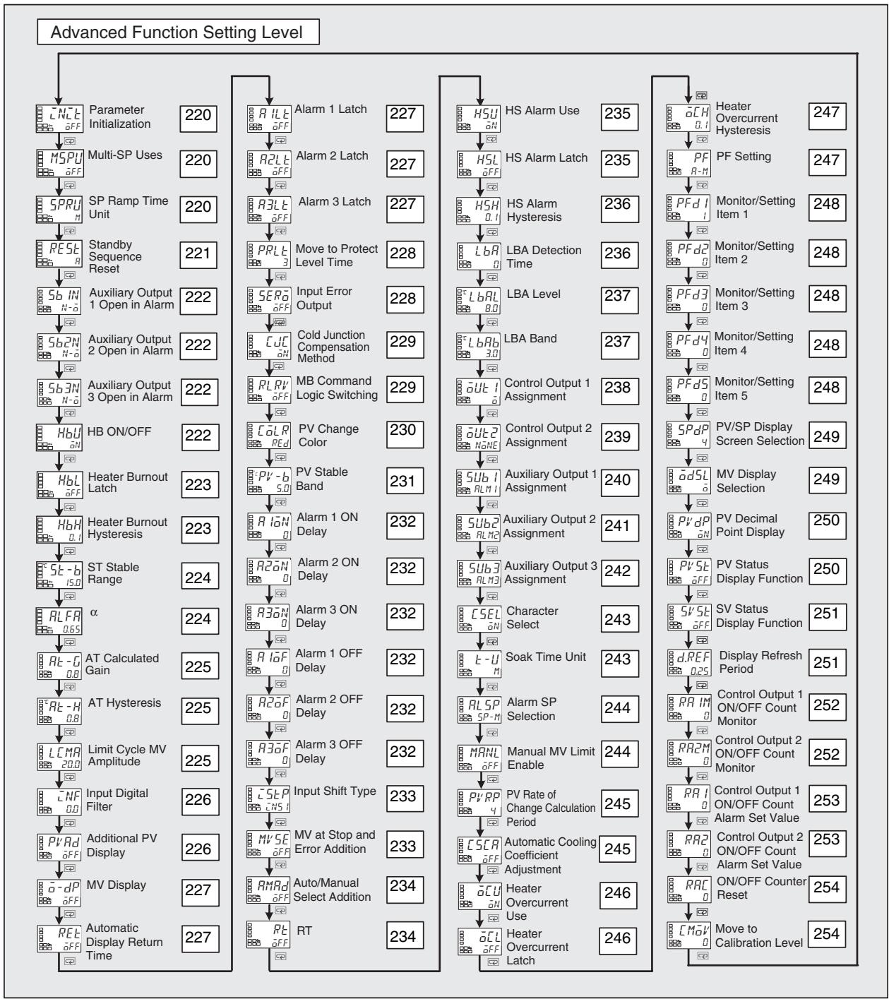
| LEET | Parameter Initialization | |
| Function | ·This parameter returns all parameter settings to their defaults. ·After the initialization, the set value automatically turns OFF. | |
| Setting | Setting range | Default |
| ☐FF: Initialization is not executed. | ☐FF | |
| FRCL: Initialized to the factory settings described in the manual. | ||
| MSPU | Multi-SP Uses | The model must not support event inputs, or the number of multi-SP uses must be 0. |
| Function | This parameter enables switching between set points 0 to 3 by operating the keys on the front panel. Prerequisites ·A model without event inputs ·The Number of Multi-SP Uses parameter set to 0 on a model with event inputs | |
| Setting | ☐N: Set points 0 to 3 can be selected. ☐FF: Set points 0 to 3 cannot be selected. ·Default: OFF | |
| See | ■Related Parameters Multi-SP set point setting (operation level): Page 167 Number of multi-SP uses (Initial setting level): Page 213 | |
| SPRU | SP Ramp Time Unit | The ST parameter must be set to OFF. |
| Function | ·This parameter sets the time unit for the rate of change during SP ramp operation. | |
| Setting | Setting range | Default |
| S: EU/s, M: EU/min, H: EU/h | M | |
| See | ■Related Parameters Ramp SP monitor (operation level): Page 167 SP ramp set value (adjustment level): Page 193 | |
RESE
Standby Sequence Reset
Alarm 1 to 3 type must be 5, 6, 7, 10, or 11.
- This parameter selects the conditions for enabling reset after the standby sequence of the alarm has been canceled.
- Output is turned OFF when switching to the initial setting level, communications setting level, advanced function setting level, or calibration level.
- Condition A
- Control started (including power ON), and set point, alarm value (alarm value upper/ lower limit), or input shift value (upper/ lower-limit temperature input shift value) changed.
Condition B Power ON - The following example shows the reset action when the alarm type is lower-limit alarm with standby sequence.
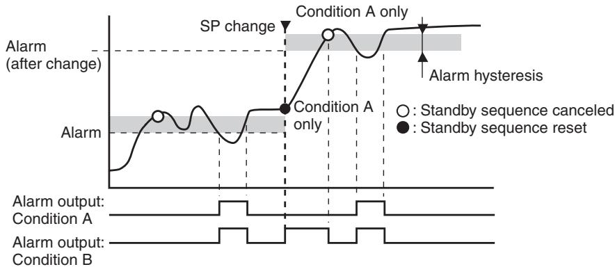
| Setting range | Default |
| R: Condition A, b: Condition B | R |

Related Parameters
Alarm 1 to 3 type (initial setting level): Page 207 to 209
Alarm 1 to 3 latch (advanced function setting level): Page 227
| 5b*N | Auxiliary Output * Open in Alarm (*: 1 to 3) | Auxiliary output 1, 2, or 3 must be assigned. | ||
| Function | ·This parameter sets the output status of auxiliary outputs 1 to 3. ·When Close in Alarm is set, the status of the auxiliary output function is output unchanged. When Open in Alarm is set, the status of the auxiliary output function is reversed before being output. The following table shows the relationship between the auxiliary output function, auxiliary output, and operation displays (SUB1 to SUB3). | |||
| Setting | Auxiliary output function | Auxiliary output | Operation display (SUB1 to SUB3) | |
| Close in Alarm | ON | ON | Lit | |
| OFF | OFF | Not lit | ||
| Open in Alarm | ON | OFF | Lit | |
| OFF | ON | Not lit | ||
| Setting range | Default | |||
| N-α: Close in alarm, N-β: Open in alarm | N-α | |||
| See | ■ Related Parameters Auxiliary output 1 to 3 assignment (advanced function setting level): Pages 240 to 242 | |||
| HbU | HB ON/OFF | Heater burnout, HS alarms, and heater overcurrent detection must be supported. Alarm 1 must be assigned. | ||
| Function | ·Set to use the heater burnout alarm. | |||
| Setting range | Default | |||
| αN: Enabled, αFF: Disabled | αN | |||
| HbL | Heater Burnout Latch | Heater burnout, HS alarms, and heater overcurrent detection must be supported. Alarm 1 must be assigned. The Heater Burnout Detection parameter must be set to ON. | ||
| Function | ·When this parameter is set to ON, the heater burnout alarm is held until either of the following conditions is satisfied. a Heater burnout detection is set to 0.0 A. b The power is cycled. c The latch is cancelled by the PF Key. (PF Setting = LAT: Alarm Latch Cancel) d The latch is cancelled by an event input. (Event Input Assignment 1 and 2 = LAT: Alarm Latch Cancel)·Output is turned OFF when switching to the initial setting level, communications setting level, advanced function setting level, or calibration level. | |||
| Setting | Setting range | Default | ||
| aN: Enabled, aFF: Disabled | aFF | |||
| See | ■ Related Parameters Event input assignment 1 and 2 (initial setting level): Page 216 HB ON/OFF: Page 222, PF setting: Page 247 (advanced function setting level) | |||
| HbH | Heater Burnout Hysteresis | The Heater Burnout parameter must be set to ON. The Heater Burnout Latch parameter must be set to OFF. Heater burnout, HS alarms, and heater overcurrent detection must be supported. Alarm 1 must be assigned. | ||
| Function | ·This parameter sets hysteresis for heater burnout detection. | |||
| Setting range | Unit | Default | ||
| 0.1 to 50.0 | A | 0.1 | ||
| Setting | ■ Related Parameters HB ON/OFF (advanced function setting level): Page 222 | |||
| 5t-b | ST Stable Range | ST must be ON and temperature input, standard control, 2-PID control must be set. | ||
| Function | The setting of this parameter determines when ST operates. This parameter cannot be used when ST is set to OFF. | |||
| Setting range | Unit | Default | ||
| 0.1 to 999.9 | °C or °F | 15.0 | ||
| See | ■ Related Parameters Input type: Page 200, PID ON/OFF: Page 204, ST: Page 205 (initial setting level) | |||
| RLFR | α | ST must be OFF and 2-PID control must be set. | ||
| Function | · Normally, use the default for this parameter. · This parameter sets the 2-PID control α constant. | |||
| Setting range | Unit | Default | ||
| 0.00 to 1.00 | None | 0.65 | ||
| See | ■ Related Parameters PID ON/OFF: Page 204, ST: Page 205 (initial setting level) | |||
| Rt-G | AT Calculated Gain | Control must be set to 2-PID control. |
| Rt-H | AT Hysteresis | |
| LCMR | Limit Cycle MV Amplitude |
- Normally use the default values for these parameters.
- The AT Calculated Gain parameter sets the gain for when PID values are calculated using AT. When emphasizing response, decrease the set value. When emphasizing stability, increase the set value.
- The AT Hysteresis parameter sets the hysteresis for limit cycle operation during autotuning when switching ON and OFF.
- The Limit Cycle MV Amplitude parameter sets the MV amplitude for limit cycle operation during autotuning.
| Parameter name | Setting range | Unit | Default |
| AT Calculated Gain | 0.1 to 10.0 | --- | 0.8 |
| AT Hysteresis | Universal input: 0.1 to 999.9 | °C or °F | 0.8 (See note.) |
| Analog input: 0.01 to 9.99 | %FS | 0.20 | |
| Limit Cycle MV Amplitude | 5.0 to 50.0 | % | 20.0 |
Note When the temperature unit is ^ F ,the default is 1.4.

Related Parameters
AT execute/cancel (adjustment level): Page 179
INF
Input Digital Filter
- This parameter sets the time constant for the input digital filter. The following diagram shows the effect on data after passing through the digital filter:

Setting
Input digital filter
| Setting range | Unit | Default |
| 0.0 to 999.9 | Second | 0.0 |
PvRd
Additional PV Display
Function
This parameter adds a display at the beginning of the operation level for the process value (PV). If there is no need to display the set point, use this to display only the present temperature.
Set to ON to display, and OFF to not display.
Setting
| Setting range | Default |
| aN: Displayed, aFF: Not displayed | aFF |
| a-dP | MV Display | |||
| Function | This parameter is used to display the manipulated variable (MV).The manipulated variable is displayed when the MV Monitor (Heating) and MV Monitor (Cooling) parameters are set to ON, and not displayed when these parameters are set to OFF. | |||
| Setting range | Default | |||
| aN: Displayed, aFF: Not displayed | aFF | |||
| See | ■ Related ParametersMV monitor (heating): Page 175, MV monitor (cooling): Page 176 (operation level) | |||
| REt | Automatic Display Return Time | |||
| Function | In the operation level, adjustment level, or monitor/setting item level, the display automatically returns to the PV/SP if there are no key operations for the time set for this parameter.The automatic display return time is disabled when the parameter is set to OFF. (In that case, the display will not be automatically switched.) | |||
| Setting range | Unit | Default | ||
| OFF, 1 to 99 | Second | aFF | ||
| Function | Alarm 1 LatchAlarm 2 LatchAlarm 3 Latch | Alarm 1 must be assigned, and the alarm 1 type must not be 0.Alarm 2 must be assigned, and the alarm 2 type must not be 0 or 12.Alarm 3 must be assigned, and the alarm 3 type must not be 0 or 12. | ||
| Function | When this parameter is set to ON, the alarm function is held until one of the following conditions is satisfied.a The power is cycled.b The latch is cancelled by the PF Key.(PF Setting = LAT: Alarm Latch Cancel)c The latch is cancelled by an event input.(Event Input Assignment 1 and 2 = LAT: Alarm Latch Cancel) | |||
| Setting range | Default | |||
| aN: Enabled, aFF: Disabled | aFF | |||
| Cold Junction Compensation Method | Input type must be thermocouple or infrared temperature sensor | |||
| Function | This parameter specifies whether cold junction compensation is to be performed internally by the Controller or to be performed externally when the input type setting is 5 to 22, 24, or 25. The cold junction compensation external setting is enabled when the temperature difference is measured using two thermocouples or two ES1B Sensors. | |||
| Setting range | Default | |||
| aN: Internally, aFF: Externally | aN | |||
| ■ Related Parameters Input type (initial setting level): Page 200 | ||||
| RLRv | MB Command Logic Switching | Communications must be supported. CompoWay/F must be selected as the protocol. | ||
| Function | This parameter switches the logic of the MB command (communications writing switch) for the SYSWAY communications protocol The MB command (communications writing switch) is the equivalent of the MB command (remote/local switch) of the E5□J. The setting indicated by the shaded cell indicates the default (same logic as E5□J). | |||
| Setting | Set value Text data of MB command | |||
| 0000 0001 | ||||
| OFF | Communications writing enabled (remote mode selection) | Communications writing disabled (local mode selection) | ||
| ON | Communications writing disabled (local mode selection) | Communications writing enabled (remote mode selection) | ||
| (Terms in parentheses () are the terms used on the E5□J.) | ||||
| See | ■ Related Parameters Communications writing (adjustment level): Page 180 Protocol setting (communications setting level): Page 255 | |||
C oL R
PV Change Color
Use the PV color change function to change the color of the PV display (No. 1 display).
There are three display colors, orange, red, and green, and you can select from the following three modes and eight types.
- Constant: This mode displays orange, red, or green all the time.
- Linked to Alarm 1: This mode switches the PV display color from red to green when alarm 1 turns ON or from green to red when alarm 1 turns ON.
- Linked to PV stable band: This mode switches the PV display color between red outside the PV stable band and green within PV stable band, or between green outside the PV stable band and red within PV stable band. Set the PV stable band in the PV Stable Band parameter in the advanced function setting level.
The default is R (red).
The following table shows the display functions that can be set using the PV color change function.
| Mode | Setting | Function | PV change color | Application example | ||
| Constant | aRb | Orange | Constant: Orange | To match the display color with other Controller models | ||
| Red | Red | Constant: Red | To match the display color with other Controller models | |||
| LRN | Green | Constant: Green | To match the display color with other Controller models | |||
| Linked to alarm 1 | ON OFF SP | Alarm value | ALM1 ON PV | |||
| ALM1 ON | ALM1 OFF | Application example | ||||
| R-R | Red to Green | Red | Green | To display the PV reached signal | ||
| L-R | Green to Red | Green | Red | To display error signals | ||
| Mode | Setting | Function | PV change color | Application example | ||
| Linked to PV stable band | Within PV stable band Low ▲ SP | |||||
| Low | PV stable band | High | Application example | |||
| R-UR | Red to Green to Red | Red | Green | Red | To display stable status | |
| U-UR | Green to Orange to Red | Green | Orange | Red | To display stable status | |
| U-UR | Orange to Green to Red | Orange | Green | Red | To display stable status | |
See
Related Parameters
PV stable band (advanced function setting level): Page 231
Pb
PV Stable Band
This parameter sets the PV stable band width within which the PV display color is changed.
- When the mode to link to the PV stable band is selected with the PV Change Color parameter, the PV display color will change according to whether the present value (PV) is lower than, within, or higher than the PV stable band, as shown in the following figure.
- There is a hysteresis of 0.2( ^ C. or ^ F ).
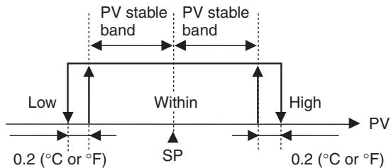
When analog inputs are used: 0.02 (%FS)
| Models | Setting range | Unit | Default |
| Controllers with Thermocouple/Resistance Thermometer Universal Inputs | 0.1 to 999.9 | °C or °F(See note.) | 5.0 |
| Controllers with Analog Inputs | 0.01 to 99.99 | %FS | 5.00 |
Note Set "None" as the unit for Controllers with Analog Inputs.

Related Parameters
PV change color (advanced function setting level): Page 230
| R10N | Alarm 1 ON Delay | Alarm 1 must be assigned, and the alarm 1 type must not be 0, 12, or 13. |
| R20N | Alarm 2 ON Delay | Alarm 2 must be assigned, and the alarm 2 type must not be 0, 12, or 13. |
| R30N | Alarm 3 ON Delay | Alarm 3 must be assigned, and the alarm 3 type must not be 0, 12, or 13. |
Alarm 1, 2, or 3 outputs are prevented from turning ON until after the delay times set in these parameters have elapsed.
- Set the time for which the ON delay is to be enabled.
- To disable the ON delay, set 0.
| Setting range | Unit | Default |
| 0 to 999 | Second | 0 |

Related Parameters
Alarm 1 to 3 type (initial setting level): Pages 207 to 210
| R10F | Alarm 1 OFF Delay | Alarm 1 must be assigned, and the alarm 1 type must not be 0, 12, or 13. |
| R20F | Alarm 2 OFF Delay | Alarm 2 must be assigned, and the alarm 2 type must not be 0, 12, or 13. |
| R30F | Alarm 3 OFF Delay | Alarm 3 must be assigned, and the alarm 3 type must not be 0, 12, or 13. |
Alarm 1, 2, or 3 outputs are prevented from turning OFF until after the delay times set in these parameters have elapsed.
- Set the time for which the OFF delay is to be enabled.
- To disable the OFF delay, set 0.
| Setting range | Unit | Default |
| 0 to 999 | Second | 0 |

Related Parameters
Alarm 1 to 3 type (initial setting level): Pages 207 to 210
| Setting range | Default |
| aN: Displayed, aFF: Not displayed | aFF |
| RMRd | Auto/Manual Select Addition | The control must be set to 2-PID control. | |
| Function | This parameter sets whether the Auto/Manual Switch parameter is to be displayed. • Set whether the Auto/Manual Switch parameter is to be displayed. | ||
| Setting range | Default | ||
| aN: Displayed, aFF: Not displayed | aFF | ||
| See | ■ Related Parameters Auto/manual switch (operation level): Page 166 | ||
| RT | RT | The control must be set to 2-PID control. The input type must be set to temperature input. | |
| Function | This parameter executes robust tuning (RT). • When AT or ST is executed with RT selected, PID constants are automatically set which make it hard for control performance to degenerate even when control object characteristics are changed. • Even when hunting occurs for PID constants when AT or ST is executed in normal mode, it is less likely to occur when AT or ST is executed in RT mode. | ||
| Setting range | Default | ||
| aN: RT function OFF, aFF: RT function ON | aFF | ||
| See | ■ Related Parameters AT execute/cancel: Page 179, Proportional band, Integral time, Derivative time: Page 188 (adjustment level) | ||
PID ON/OFF: Page 204, ST: Page 205 (initial setting level)
| HSU | HS Alarm Use | Heater burnout, HS alarms, and heater overcurrent detection must be supported. Alarm 1 must be assigned. | |
| Function | · Set this parameter to use HS alarms. | ||
| Setting | Setting range | Default | |
| aN: Enabled, aFF: Disabled | aN | ||
| HSL | HS Alarm Latch | Heater burnout, HS alarms, and heater overcurrent detection must be supported. Alarm 1 must be assigned. The HS Alarm parameter must be set to ON. | |
| Function | · When this parameter is set to ON, the HS alarm is held until any of the following conditions is satisfied. a The HS alarm current is set to 50.0 A. b The power is cycled. c The latch is cancelled by the PF Key. (PF Setting = LAT: Alarm Latch Cancel) d The latch is cancelled by an event input. (Event Input Assignment 1 and 2 = LAT: Alarm Latch Cancel) · Output is turned OFF when switching to the initial setting level, communications setting level, advanced function setting level, or calibration level. | ||
| Setting | Setting range | Default | |
| aN: Enabled, aFF: Disabled | OFF | ||
| See | ■ Related Parameters | ||
| HS alarm use (advanced function setting level): Page 235 Event input assignment 1 and 2 (initial setting level): Page 216 HB ON/OFF: Page 222, PF setting: Page 247 (advanced function setting level) | |||
| H5H | HS Alarm Hysteresis | Heater burnout and HS alarms must be supported. Alarm 1 must be assigned. The HS Alarm parameter must be set to ON. The HS Alarm Latch parameter must be set to OFF. | ||
| Function | ·This parameter sets the hysteresis for HS alarms. | |||
| Setting range | Unit | Default | ||
| 0.1 to 50.0 | A | 0.1 | ||
| Setting | ||||
| See | ■ Related Parameters HS alarm use (advanced function setting level): Page 235 | |||
| LbR | LBA Detection Time | Alarm 1 must be assigned. The alarm type must be set to 12 (LBA). | ||
| Function | This parameter enables or disables the LBA function and sets the detection time interval. ·Set the time interval for detecting loop burnouts. ·To disable the LBA function, set 0. | |||
| Setting range | Unit | Default | ||
| 0 to 9999 | Second | 0 | ||
| See | ■ Related Parameters Alarm 1 type (initial setting level): Page 207 LBA level: Page 237, LBA band: Page 237 (advanced function setting level) | |||
| Models | Setting range | Unit | Default | |
| Controllers with Thermocouple/Resis- tance Thermometer Universal Inputs | 0.0 to 999.9 | °C or °F (See note.) | 8.0 | |
| Controllers with Analog Inputs | 0.01 to 99.99 | %FS | 10.00 | |
| Note | Set “None” as the unit for Controllers with Analog Inputs. | |||
| LbRb | LBA Band | Alarm 1 must be assigned. The alarm type must be set to 12 (LBA). The LBA detection time must not be 0. | ||
| Function | ·This parameter sets the LBA band. ·If a control deviation greater than the LBA band is not reduced when the LBA level is exceeded, an loop burnout is detected. | |||
| Setting | Models | Setting range | Unit | |
| Controllers with Thermocouple/Resis- tance Thermometer Universal Inputs | 0.0 to 999.9 | °C or °F (See note.) | 3.0 | |
| Controllers with Analog Inputs | 0.00 to 99.99 | %FS | 0.20 | |
| Note | Set “None” as the unit for Controllers with Analog Inputs. | |||
out
Control Output 1 Assignment
The transfer output type must be set to OFF when the control output is a current output.
Function
Setting
- This parameter sets the function to be assigned to control output 1.
| Setting range | Default |
| nNone: No function is assigned to control output 1. | a |
| a: Heating control output is output. | |
| C - a: Cooling control output is output. (See note 1.) | |
| RLM1: Alarm 1 is output. (See note 2.) | |
| RLM2: Alarm 2 is output. (See note 2.) | |
| RLM3: Alarm 3 is output. (See note 2.) | |
| PEND: Program end is output. (See notes 2 and 3.) | |
| RALM: Control output ON/OFF count alarm (See note 2.) | |
| WR1: Work bit 1 (See notes 2 and 4.) | |
| WR2: Work bit 2 (See notes 2 and 4.) | |
| WR3: Work bit 3 (See notes 2 and 4.) | |
| WR4: Work bit 4 (See notes 2 and 4.) | |
| WR5: Work bit 5 (See notes 2 and 4.) | |
| WR6: Work bit 6 (See notes 2 and 4.) | |
| WR7: Work bit 7 (See notes 2 and 4.) | |
| WR8: Work bit 8 (See notes 2 and 4.) |
Note
(1) If - is assigned for standard control, a value equivalent to 0% is output.
(2) Can be selected for relay and voltage outputs (for driving SSR) only.
(3) Can be selected when the Program Pattern parameter is set to OFF, but the function will be disabled.
(4) WR1 to WR8 are not displayed when the logic operation function is not used.
See
Related Parameters
Standard or heating/cooling: Page 204, Program pattern: Page 205, Transfer output type: Page 210 (initial setting level)
aUT2
Control Output 2 Assignment
Control output 2 must be assigned.
Function
Setting
- This parameter sets the function to be assigned to control output 2.
| Setting range | Default |
| NNone: No function is assigned to control output 2. | NNone (See note 3.) |
| a: Heating control output is output. | |
| C - a: Cooling control output is output. (See note 1.) | |
| RLM1: Alarm 1 is output. | |
| RLM2: Alarm 2 is output. | |
| RLM3: Alarm 3 is output. | |
| PEND: Program end is output. (See note 2.) | |
| RRLM: Control output ON/OFF count alarm | |
| WR1: Work bit 1 (See note 4.) | |
| WR2: Work bit 2 (See note 4.) | |
| WR3: Work bit 3 (See note 4.) | |
| WR4: Work bit 4 (See note 4.) | |
| WR5: Work bit 5 (See note 4.) | |
| WR6: Work bit 6 (See note 4.) | |
| WR7: Work bit 7 (See note 4.) | |
| WR8: Work bit 8 (See note 4.) |
Note
(1) If - is assigned for standard control, a value equivalent to 0% will be output.
(2) Can be selected when the Program Pattern parameter is set to OFF, but the function will be disabled.
(3) If the Standard or Heating/Cooling parameter is set to heating/cooling control, control automatically switches to - .
(4) WR1 to WR8 are not displayed when the logic operation function is not used.
See
Related Parameters
Standard or heating/cooling: Page 204, Program pattern: Page 205, (initial setting level)
SUB1
Auxiliary Output 1 Assignment
Auxiliary output 1 must be assigned.

- This parameter sets the function to be assigned to auxiliary output 1.
| Setting range | Default |
| NNone: No function is assigned to auxiliary output 1. | RLM1(See note3.)(See note5.) |
| a: Heating control output is output. | |
| C - a: Cooling control output is output. (See note 1.) | |
| RLM1: Alarm 1 is output. | |
| RLM2: Alarm 2 is output. | |
| RLM3: Alarm 3 is output. | |
| PEND: Program end is output. (See note 2.) | |
| RRLM: Control output ON/OFF count alarm | |
| WR1: Work bit 1 (See note 4.) | |
| WR2: Work bit 2 (See note 4.) | |
| WR3: Work bit 3 (See note 4.) | |
| WR4: Work bit 4 (See note 4.) | |
| WR5: Work bit 5 (See note 4.) | |
| WR6: Work bit 6 (See note 4.) | |
| WR7: Work bit 7 (See note 4.) | |
| WR8: Work bit 8 (See note 4.) |
Note
(1) If - is assigned for standard control, a value equivalent to 0% will be output.
(2) Can be selected when the Program Pattern parameter is set to OFF, but the function will be disabled.
(3) If a setting is changed when the Program Pattern parameter is not set to OFF, control automatically switches to P.ENd .
(4) WR1 to WR8 are not displayed when the logic operation function is not used.
(5) If the Standard or Heating/Cooling parameter is set to heating/cooling control, this parameter will automatically be set to - .
See
Related Parameters
Program pattern (initial setting level): Page 205
SUB2
Auxiliary Output 2 Assignment
Auxiliary output 2 must be assigned.
- This parameter sets the function to be assigned to auxiliary output 2.
| Setting range | Default |
| N0NE: No function is assigned to auxiliary output 2. | RLM2 (See note 3.) |
| a: Heating control output is output. | |
| C - a: Cooling control output is output. (See note 1.) | |
| RLM1: Alarm 1 is output. | |
| RLM2: Alarm 2 is output. | |
| RLM3: Alarm 3 is output. | |
| PEND: Program end is output. (See note 2.) | |
| RRLM: Control output ON/OFF count alarm | |
| WR1: Work bit 1 (See note 4.) | |
| WR2: Work bit 2 (See note 4.) | |
| WR3: Work bit 3 (See note 4.) | |
| WR4: Work bit 4 (See note 4.) | |
| WR5: Work bit 5 (See note 4.) | |
| WR6: Work bit 6 (See note 4.) | |
| WR7: Work bit 7 (See note 4.) | |
| WR8: Work bit 8 (See note 4.) |
Note
(1) If - is assigned for standard control, a value equivalent to 0% will be output.
(2) Can be selected when the Program Pattern parameter is set to OFF, but the function will be disabled.
(3) If the Standard or Heating/Cooling parameter is set to heating/cooling control when there is no control output 2 (E5CN/CN-U), control automatically switches to ^-0
(4) WR1 to WR8 are not displayed when the logic operation function is not used.
See
Related Parameters
Standard or heating/cooling: Page 204, Program pattern: Page 205, (initial setting level)
5u63
Auxiliary Output 3 Assignment
Auxiliary output 3 must be assigned (E5AN and E5EN only).
Function
- This parameter sets the function to be assigned to Auxiliary output 3.
| Setting range | Default |
| NNone: No function is assigned to auxiliary output 3. | RLM3(See note 3.) |
| a: Heating control output is output. | |
| C - a: Cooling control output is output. (See note 1.) | |
| RLM1: Alarm 1 is output. | |
| RLM2: Alarm 2 is output. | |
| RLM3: Alarm 3 is output. | |
| PEND: Program end is output. (See note 2.) | |
| RRLM: Control output ON/Off count alarm | |
| WR1: Work bit 1 (See note 4.) | |
| WR2: Work bit 2 (See note 4.) | |
| WR3: Work bit 3 (See note 4.) | |
| WR4: Work bit 4 (See note 4.) | |
| WR5: Work bit 5 (See note 4.) | |
| WR6: Work bit 6 (See note 4.) | |
| WR7: Work bit 7 (See note 4.) | |
| WR8: Work bit 8 (See note 4.) |
Note
(1) If - is assigned for standard control, a value equivalent to 0% will be output.
(2) Can be selected when the Program Pattern parameter is set to OFF, but the function will be disabled.
(3) If the Standard or Heating/Cooling parameter is set to heating/cooling control when there is no control output 2 (E5AN/EN), control automatically switches to - .
(4) WR1 to WR8 are not displayed when the logic operation function is not used.
Related Parameters
Standard or heating/cooling: Page 204, Program pattern: Page 205, (initial setting level)

| C5EL | Character Select | |
| Function | ·This parameter switches the characters to be displayed. The following two types of characters can be displayed. 11-segment display 7-segment display | |
| Setting | Setting range | Default |
| aN: 11-segment display, aFF: 7-segment display | aN | |
| When set to aN, an 11-segment display is used. | ||
| E-U | Soak Time Unit | The Program Pattern parameter must not be set to OFF. |
Function

Setting

- Set the soak time unit for the simple program function.
| Setting range | Default |
| M: Minutes, H: Hours | M |
Related Parameters
Program start, Soak time remain (operation level): Page 171
Soak time, Wait band (adjustment level): Page 191
Program pattern (initial setting level): Page 205
| RL 5P | Alarm SP Selection | Alarm 1, 2, and 3 functions must be assigned. The SP Ramp Set Value parameter must not be set to OFF. The ST parameter must be set to OFF. The alarm type must be set to 1, 2, 3, 4, 5, 6, or 7. | |
| Function | This parameter sets whether the set point that triggers a deviation alarm during SP ramp operation is to be the ramp SP or target SP. • Set whether the set point that triggers a deviation alarm is the ramp SP or target SP. | ||
| Setting range | Default | ||
| 5P-M: Ramp SP, 5P: SP | 5P-M | ||
| See | ■ Related Parameters SP ramp set value (adjustment level): Page 193 ST (initial setting level): Page 205 | ||
| MANL | Manual MV Limit Enable | The control must be set to 2-PID control. | |
| Function | This parameter sets whether the MV Upper Limit and MV Lower Limit parameters are to be enabled for manual MV in manual mode. | ||
| Setting | Setting range | Default | |
| aN: Enabled, aFF: Disabled | OFF | ||
| See | ■ Related Parameters MV upper limit, MV lower limit (adjustment level): Page 193 | ||
| PV RP | PV Rate of Change Calculation Period | Alarms 1, 2, and 3 must be assigned. The alarm type must be set to 13. | |
| Function | · The change width can be found for PV input values in any set period. Dif- ferences with previous values in each set period are calculated, and an alarm is output if the results exceed the alarm value. · The PV rate of change calculation period can be set in units of 250 ms (sampling period). | ||
| Setting | Setting range | Unit | Default |
| 1 to 999 | Sampling period | 4 (1 s) | |
| See | ■ Related Parameters Present value, Process value/set point (operation level): Page 165 Alarm 1 to 3 type, (Initial setting level): Pages 207 to 210 | ||
| C5CR | Automatic Cooling Coefficient Adjust- ment | The control must be set to heating/ cooling control and 2-PID control. | |
| Function | · By setting the Automatic Cooling Coefficient Adjustment parameter to ON, autotuning can be executed during heating/cooling control to auto- matically calculate the cooling coefficient at the same time as the PID parameters. If there is strong non-linear gain for the cooling characteris- tics, such as when cooling water boils for cooling control, it may not be possible to obtain the optimum cooling coefficient at the Controller, and control may take the form of oscillating waves. If that occurs, increase the proportional band or the cooling coefficient to improve control. | ||
| Setting | Setting range | Default | |
| aN: Enabled, aFF: Disabled | OFF | ||
| See | ■ Related Parameters Cooling coefficient (adjustment level): Page 189 | ||
| aCU | Heater Overcurrent Use | Heater burnout, HS alarms, and heater overcurrent detection must be supported. Alarm 1 must be assigned. |
| Function | • Set this parameter to use the heater overcurrent alarm. | |
| Setting | Setting range | Default |
| aN: Enabled, aFF: Disabled | ON | |
| aCL | Heater Overcurrent Latch | Heater burnout, HS alarms, and heater overcurrent detection must be supported (two CTs). Alarm 1 must be assigned. |
| Function | • When this parameter is set to ON, the heater overcurrent alarm is held until any of the following conditions is satisfied. a Heater overcurrent detection is set to 50.0 A. b The power is cycled. c The latch is cancelled by the PF Key. (PF Setting = LAT: Alarm Latch Cancel) d The latch is cancelled by an event input. (Event Input Assignment 1 and 2 = LAT: Alarm Latch Cancel) | |
| Setting | • Output is turned OFF when switching to the initial setting level, communications setting level, advanced function setting level, or calibration level. | |
| Setting range | Default | |
| aN: Enabled, aFF: Disabled | OFF | |
| See | ■ Related Parameters | |
| Heater overcurrent detection 1, Heater overcurrent detection 2 (adjustment level): Pages 181, and 183 | ||
| Heater overcurrent use (advanced function setting level): Page 246 | ||
| Heater overcurrent hysteresis (advanced function setting level): Page 247 | ||
| Event input assignment 1 and 2 (initial setting level): Page 216 | ||
| HB ON/OFF: Page 222, PF setting: Page 247 (advanced function setting level) | ||
| a[H] | Heater Overcurrent Hysteresis | Heater burnout, HS alarms, and heater overcurrent detection must be supported, and alarm 1 must be assigned. The Heater Overcurrent Use parameter must be set to ON, and the Heater Overcurrent Latch parameter must be set to OFF. | |
| Setting range | Unit | Default | |
| 0.1 to 50.0 | A | 0.1 | |
| Function | This parameter sets the hysteresis for heater overcurrent detection. | ||
| Setting | Setting range | Unit | Default |
| 0.1 to 50.0 | A | 0.1 | |
| See | ■ Related Parameters Heater overcurrent use (advanced function setting level): Page 246 | ||
| PF | PF Setting | The PF Key must be supported (E5AN/EN). | |
| Function | This parameter sets the function of the PF Key. The default is A-M. | ||
| Setting | Set value | Setting | Function |
| OFF: OFF | Disabled | Does not operate as a function key. | |
| RUN: RUN | RUN | Specifies RUN status. | |
| STOP: 5εδP | STOP | Specifies STOP status. | |
| R-S: R-5 | Reversing RUN/STOP operation | Specifies reversing RUN/STOP operation status. | |
| AT-2: R-2 | 100%AT Execute/Cancel | Specifies reversing 100% AT Execute/Cancel status. (See note 1.) | |
| AT-1: R-1 | 40%AT Execute/Cancel | Specifies reversing 40% AT Execute/Cancel status. (See note 1.) | |
| LAT: LRL | Alarm Latch Cancel | Specifies canceling alarm latches. (See note 2.) | |
| A-M: R-M | Auto/Manual | Specifies reversing Auto/Manual status (See note 3.) | |
| PFDP: PFdP | Monitor/Setting Item | Specifies the monitor/setting item display. Select the monitor/setting item using the Monitor/Setting Item 1 to 5 parameters (advanced function setting level). | |
| Note | (1) When AT cancel is specified, it means that AT is cancelled regardless of whether the AT currently being executed is 100% AT or 40% AT. | ||
(2) Alarms 1 to 3, heater burnout, HS alarms, and heater overcurrent latches are cancelled.
(3) For details on auto/manual operations using the PF Key, refer to 4-13 Performing Manual Control.

Related Parameters
Monitor/setting item 1 to 5 (advanced function setting level): Page 248
PFd*
Monitor/Setting Item * (*: 1 to 5)
The PF Setting parameter must be set to PFDP.
- Set the PF Key parameter to Monitor/Setting Item to enable using the function key to display monitor/setting items. The items that will be displayed are set using the Monitor/Setting Item 1 to 5 parameters. The settings are listed in the following table.
| Set value | Setting | Remarks | |
| Monitor/Setting | Symbol | ||
| 0 | Disabled | --- | |
| 1 | PV/SP/Multi-SP | Can be set. (SP) | --- |
| 2 | PV/SP/MV (See note.) | Can be set. (SP) | --- |
| 3 | PV/SP/Soak time remain | Can be set. (SP) | --- |
| 4 | Proportional band (P) | Can be set. | P |
| 5 | Integral time (I) | Can be set. | L |
| 6 | Derivative time (D) | Can be set. | d |
| 7 | Alarm value 1 | Can be set. | RL - I |
| 8 | Alarm value upper limit 1 | Can be set. | RL IH |
| 9 | Alarm value lower limit 1 | Can be set. | RL IL |
| 10 | Alarm value 2 | Can be set. | RL - 2 |
| 11 | Alarm value upper limit 2 | Can be set. | RL 2H |
| 12 | Alarm value lower limit 2 | Can be set. | RL 2L |
| 13 | Alarm value 3 | Can be set. | RL - 3 |
| 14 | Alarm value upper limit 3 | Can be set. | RL 3H |
| 15 | Alarm value lower limit 3 | Can be set. | RL 3L |
Note The MV for heating and cooling control is set in the MV Display Selection parameter.

Related Parameters
PF setting: Page 247, MV display selection: Page 249 (advanced function setting level)
| SPdP | PV/SP Display Screen Selection | The No. 3 display must be supported (E5AN/EN). |
| Function | ·This parameter sets the PV/SP Screen No. 3 display and order of display. ·The default is 4.* ·A 2-level display is set at the time of shipping from the factory. (set value: 0) A 3-level display is activated if parameters are initialized. (set value: 4) | |
| Setting | Set value | Display contents |
| 0 | Only PV/SP is displayed (with no No. 3 display). | |
| 1 | PV/SP/Multi-SP and PV/SP/MV are displayed in order. (See note.) | |
| 2 | PV/SP/MV and PV/SP/Multi-SP are displayed in order. (See note.) | |
| 3 | Only PV/SP/Multi-SP is displayed. | |
| 4 | PV/SP/MV is displayed (See note.) | |
| 5 | PV/SP/Multi-SP and PV/SP/Soak time remain are displayed in order. (See note.) | |
| 6 | PV/SP/MV and PV/SP/Soak time remain are displayed in order. (See note.) | |
| 7 | Only PV/SP/Soak time remain is displayed. | |
| See | Note | The MV for heating and cooling control is set in the MV Display Selection parameter. |
| ■ Related Parameters Process value/set point (operation level): Page 165 MV display selection (advanced function setting level): Page 249 | ||
| dd5L | MV Display Selection | The No. 3 display must be supported (E5AN/EN). Heating and cooling control must be used. The PV/SP Display Screen Selection parameter must be set to 1, 2, 4, or 6, or the Monitor/Setting Item 1 to 5 parameter must be set to 2. |
| Function | ·This parameter selects the MV display for PV/SP/MV during heating and cooling control. Either heating MV or cooling MV can be selected. | |
| Setting | Setting range | Default |
| ○: MV (heating) [ - ○: MV (cooling) | ○ | |
| PV dP | PV Decimal Point Display | The input type must be set to temperature input. |
| Function | The display below the decimal point in the PV can be hidden for temperature inputs. · The PV decimals below the decimal point can be hidden by setting the PV Decimal Point Display parameter to OFF. When this parameter is set to ON, the display below the decimal point will appear according to the input type setting. | |
| Setting | Setting range | Default |
| aN: ON, aFF: OFF | ON | |
| See | ■ Related Parameters Input type (initial setting level): Page 200 | |
| PV 5e | PV Status Display Function | |
| Function | · The PV in the No. 1 display for the PV/SP, PV, or PV/Manual MV Screen is alternately displayed in 0.5-s cycles with the control and alarm status specified for the PV status display function. | |
| Monitor | Monitor range | Default |
| aFF: No PV status display | aFF | |
| MRNU: MANU is alternately displayed during manual control. | ||
| 5e-0P: STOP is alternately displayed while operation is stopped. | ||
| RLM1: ALM1 is alternately displayed during Alarm 1 status. | ||
| RLM2: ALM2 is alternately displayed during Alarm 2 status. | ||
| RLM3: ALM3 is alternately displayed during Alarm 3 status. | ||
| RLM4: ALM is alternately displayed when Alarm 1, 2, or 3 is set to ON. | ||
| HA: HA is alternately displayed when a heater burnout alarm, HS alarm, or heater overcurrent alarm is ON. | ||
| See | ■ Related Parameters Process value/set point, PV (operation level): Page 165 PV/MV (manual MV) (manual control level): Page 197 | |
515
SV Status Display Function
Function
Monitor
- The SP, Blank, or Manual MV in the No. 2 display for the PV/SP, PV, or PV/Manual MV Screen is alternately displayed in 0.5-s cycles with the control and alarm status specified for the SV status display function.
| Monitor range | Default |
| ☐FF: No SV status display | ☐FF |
| MANU: MANU is alternately displayed during manual control. | |
| ☐E ☐P: STOP is alternately displayed while operation is stopped. | |
| RLM1: ALM1 is alternately displayed during Alarm 1 status. | |
| RLM2: ALM2 is alternately displayed during Alarm 2 status. | |
| RLM3: ALM3 is alternately displayed during Alarm 3 status. | |
| RLM: ALM is alternately displayed when Alarm 1, 2, or 3 is set to ON. | |
| HR: HA is alternately displayed when a heater burnout alarm, HS alarm, or heater overcurrent alarm is ON. |

Related Parameters
Process value/set point, PV (operation level): Page 165
PV/MV (manual MV) (manual control level): Page 197
d.REF
Display Refresh Period
Function
- This parameter delays the display refresh period for monitor values. Only display refreshing is delayed, and the refresh period for process values used in control is not changed.
- This function is disabled by setting the parameter to OFF.
Monitor
| Setting range | Unit | Default |
| OFF, 0.25, 0.5, 1.0 | Second | 0.25 |
| RR IM | Control Output 1 ON/OFF Count Monitor | Control output 1 must be supported. Relay or voltage outputs (for driving SSR) must be used. The Control Output 1 ON/OFF Count Alarm Set Value parameter must not be set to 0. |
| Function | ·This parameter monitors the number of times that control output 1 is turned ON and OFF. ·This function is not displayed when the set value is 0, or when the control output is a linear output. | |
| Monitor | Monitor range | Unit |
| 0 to 9999 | 100 times | |
| RHA2M | Control Output 2 ON/OFF Count Monitor | Control output 2 must be supported. Relay or voltage outputs (for driving SSR) must be used. The Control Output 2 ON/OFF Count Alarm Set Value parameter must not be set to 0. |
| Function | ·This parameter monitors the number of times that control output 2 is turned ON and OFF. ·This function is not displayed when the set value is 0, or when the control output is a linear output. | |
| Monitor | Monitor range | Unit |
| 0 to 9999 | 100 times | |
| RR1 | Control Output 1 ON/OFF Count Alarm Set Value | Control output 1 must be supported. Relay or voltage outputs (for driving SSR) must be used. | |
| Function | ·An ON/OFF count alarm occurs when the ON/OFF counter exceeds the value set for this parameter. ·It is possible to assign ON/OFF count alarms to auxiliary outputs and to have them displayed on the screen. ·This function is disabled when the set value is 0. | ||
| Monitor | Setting range | Unit | Default |
| 0 to 9999 | 100 times | 0 | |
| See | ■ Related Parameters Control output 1 ON/OFF count monitor (advanced function setting level): Page 252 | ||
| RR2 | Control Output 2 ON/OFF Count Alarm Set Value | Control output 2 must be supported. Relay or voltage outputs (for driving SSR) must be used. | |
| Function | ·An ON/OFF count alarm occurs when the ON/OFF counter exceeds the value set for this parameter. ·It is possible to assign ON/OFF count alarms to auxiliary outputs and to have them displayed on the screen. ·This function is disabled when the set value is 0. | ||
| Monitor | Setting range | Unit | Default 0 to 9999 |
| 100 times | 0 | ||
| See | ■ Related Parameters Control output 2 ON/OFF count monitor (advanced function setting level): Page 252 | ||
| RAC | ON/OFF Counter Reset | Control outputs 1 and 2 must be supported. Relay or voltage outputs (for driving SSR) must be used. |
| Function | · This parameter resets the ON/OFF counter for specified control outputs. | |
| Setting range | Default | |
| 0: Disable the counter reset function. 1: Reset the control output 1 ON/OFF counter. 2: Reset the control output 2 ON/OFF counter. | 0 | |
| See | Note | After the counter has been reset, the set value will be automatically returned to 0. |
| ■ Related Parameters Control output 1 ON/OFF count monitor, Control output 2 ON/OFF count monitor (advanced function setting level): Page 252 | ||
| [MaV] | Move to Calibration Level | Initial setting/communications protect must be 0. |
| Function | This parameter sets the password to move to the calibration level. · Set the password to move to the calibration level. The password is 1201. · Move to the calibration level either by pressing the Key or Key or by waiting for two seconds to elapse. | |
| See | ■ Related Parameter Initial setting/communications protect (protect level): Page 160 | |
5-9 Communications Setting Level
P5EL
Protocol Setting
Communications must be supported.
U-Na
Communications Unit No.
bP5
Communications Baud Rate
LEN
Communications Data Length
CompoWay/F must be selected as the protocol.
5b1t
Communications Stop Bits
CompoWay/F must be selected as the protocol.
PRTY
Communications Parity
5dwt
Send Data Wait Time
Each parameter is enabled when the power is reset.
- Match the communications specifications of the E5□N and the host computer. If multiple devices are connected, ensure that the communications specifications for all devices in the system (except the Communications unit number) are the same.
| Item | Symbol | Set values | Settings | Default |
| Protocol setting | PSEL | CWF, Mod | CompoWay/F (SYSWAY), Modbus | CWF |
| Communications Unit No. | U-No | 0 to 99 | 0 to 99 | 1 |
| Communications baud rate | bPS | 1.2, 2.4, 4.8, 9.6, 19.2, 38.4, or 57.6 (kbps) | 1.2, 2.4, 4.8, 9.6, 19.2, 38.4, or 57.6 (kbps) | 9.6 |
| Communications data length | LEN | 7 or 8 bits | 7 or 8 bits | 7 |
| Stop bits | SbLT | 1 or 2 bits | 1 or 2 bits | 2 |
| Communications parity | PREY | None, EVEN, add | None, Even, Odd | EVEN |
| Send data wait time | SdWt | 0 to 99 | 0 to 99 (ms) | 20 |
See
Related Parameter
Communications writing (adjustment level): Page 180
SECTION 6
CALIBRATION
This section describes how the user can calibrate the E5CN and E5CN-U Digital Temperature Controllers.
6-1 Parameter Structure 258
6-2User Calibration 260
6-2-1 Calibrating Inputs 260
6-2-2 Registering Calibration Data 260
6-3 Thermocouple Calibration (Thermocouple/Resistance Thermometer Input). 260
6-3-1 Preparations 261
6-4 Platinum Resistance Thermometer Calibration (Thermocouple/Resistance Thermometer Input) 264
6-5 Analog Input Calibration (Thermocouple/Resistance Thermometer Input). 265
6-6 Calibrating Analog Input (Analog Input) 267
6-6-1 Calibrating a Current Input. 267
6-6-2 Calibrating a Voltage Input. 268
6-7 Checking Indication Accuracy 270
6-7-1 Thermocouple or Infrared Temperature Sensor 270
6-7-2 Platinum Resistance Thermometer 271
6-7-3 Analog Input. 272
6-1 Parameter Structure
- To execute user calibration, enter the password "1201" at the Move to Calibration Level parameter in the advanced function setting level. The mode will be changed to the calibration mode, and dU will be displayed.
- The Move to Calibration Level parameter may not be displayed when the user is doing the calibration for the first time. If this happens, set the Initial Setting/Communications Protect parameter in the protect level to 0 before moving to the advanced function setting level.
- The calibration mode is ended by turning the power OFF.
- The parameter calibrations in the calibration mode are structured as shown below.
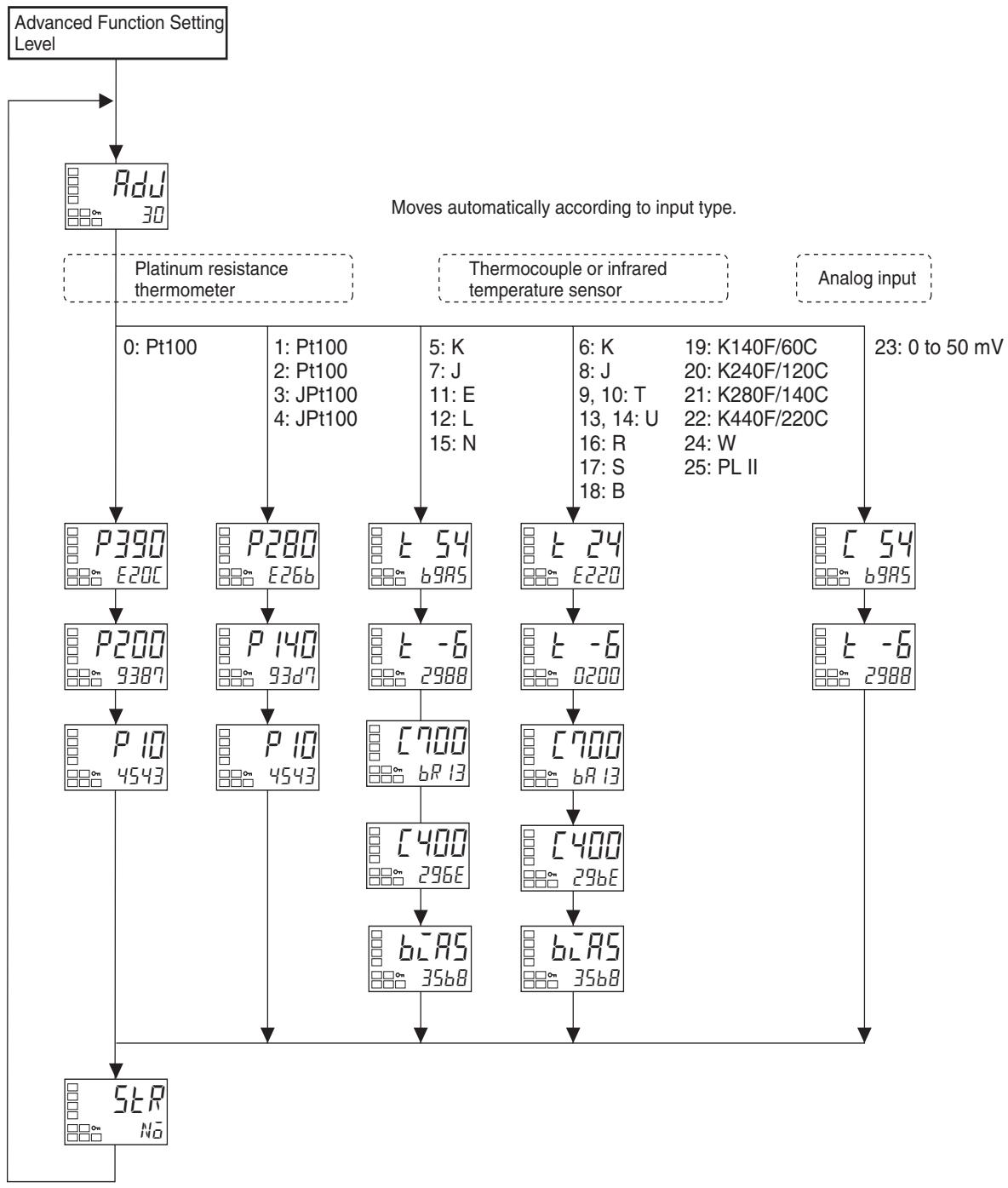
Controllers with Thermocouple/Resistance Thermometer Universal Inputs
Controllers with an Analog Input
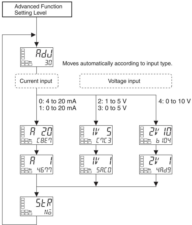
When calibration has been performed after purchase, the user calibration information shown in the following illustration will be displayed when moving to the calibration level.
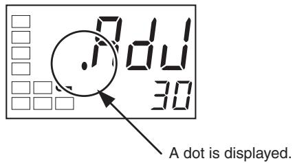
6-2 User Calibration
The E5CN/CN-U/AN/EN/GN is correctly calibrated before it is shipped from the factory, and normally need not be calibrated by the user.
If, however, it must be calibrated by the user, use the parameters for calibrating temperature input and analog input. OMRON, however, cannot ensure the results of calibration by the user. Also, calibration data is overwritten with the latest calibration results. The default calibration settings cannot be restored after user calibration. Perform user calibration with care.
6-2-1 Calibrating Inputs
The input type selected in the parameter is used for calibration. The input types are as follows:
Controllers with Thermocouple/Resistance Thermometer Universal Inputs
Thermocouple: 16 types
- Infrared temperature sensor: 4 types
- Analog input: 1 type
- Platinum resistance thermometer: 5 types
Controllers with Analog Inputs
- Current input: 2 types
Voltage input: 3 types
6-2-2 Registering Calibration Data
The new calibration data for each item is temporarily registered. It can be officially registered as calibration data only when all items have been calibrated to new values. Therefore, be sure to temporarily register all items when you perform the calibration. When the data is registered, it is also recorded that user calibration has been performed.
Prepare separate measuring devices and equipment for calibration. For details on how to handle measuring devices and equipment, refer to the respective instruction manuals.
6-3 Thermocouple Calibration (Thermocouple/Resistance Thermometer Input)
- Calibrate according to the type of thermocouple: thermocouple 1 group (input types 5, 7, 11, 12, 15) and thermocouple 2 group (input types 6, 8, 9, 10, 13, 14, 16, 17, 18, 19, 20, 21, 22, 24, 25).
- When calibrating, do not cover the bottom of the Controller. Also, do not touch input terminals/pins (terminals 4 and 5 on the E5CN, pins 1 and 2 on the E5CN-U, pins 19 and 20 on the E5AN/E5EN, or pins 11 and 12 on the E5GN) or compensating conductors.
6-3-1 Preparations
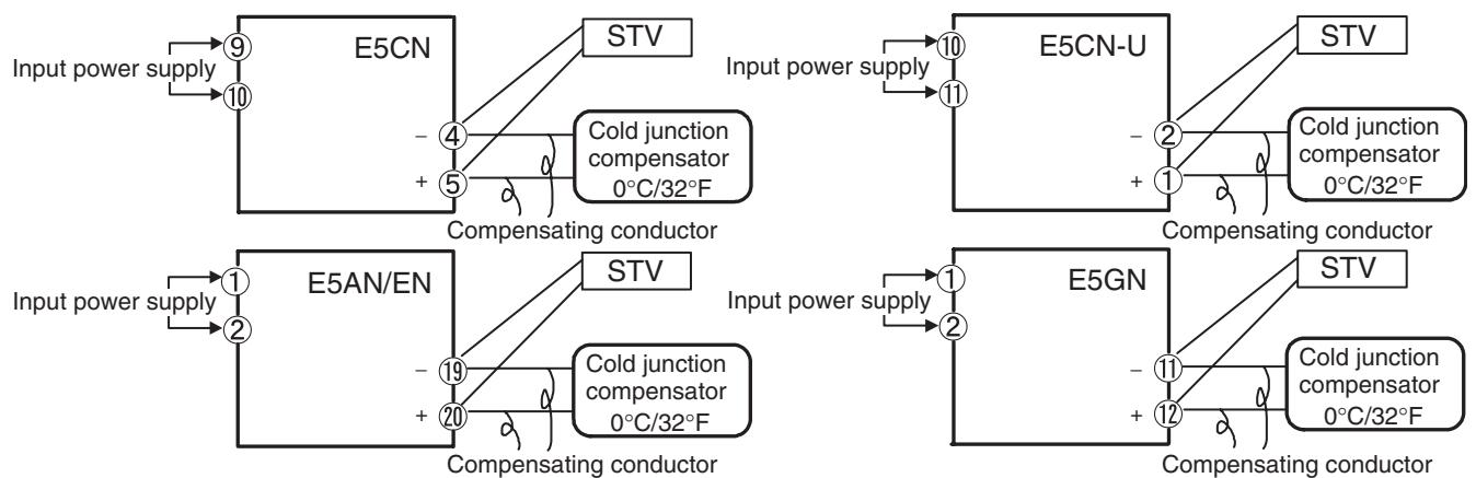
- Set the cold junction compensator designed for compensation of internal thermocouples to 0^ . Make sure that internal thermocouples are disabled (i.e., that tips are open).
- In the above figure, STV indicates a standard DC current/voltage source.
- Use the compensating conductor designed for the selected thermocouple. When thermocouples R, S, E, B, W, or PLII or an infrared temperature sensor is used, the cold junction compensator and the compensating conductor can be substituted with the cold junction compensator and the compensating conductor for thermocouple K.
- Connecting the Cold Junction Compensator
Correct process values cannot be obtained if you touch the contact ends of the compensating conductor during calibration of a thermocouple. Accordingly, short-circuit (enable) or open (disable) the tip of the thermocouple inside the cold junction compensator as shown in the figure below to create a contact or non-contact state for the cold junction compensator.
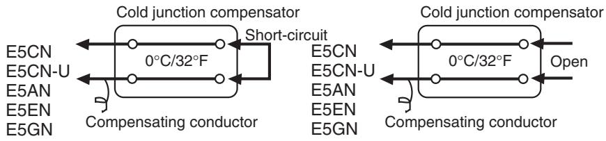
In this example, calibration is shown for a Controller with a Thermocouple/ Resistance Thermometer Universal Input, with thermocouple/infrared temperature sensor set as the input type.
1,2,3... 1. Connect the power supply.
- Connect a standard DC current/voltage source (STV), precision digital multimeter (DMM), and contact junction compensator (e.g., a zero controller as in the figure) to the thermocouple input terminals, as shown in the figure below.
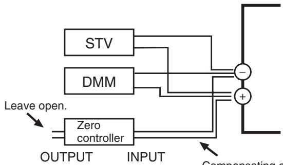
Compensating conductor of currently selected thermocouple.
Use K thermocouple compensating conductor for E, R, S, B, W, and PLII thermocouples and for an infrared temperature sensor.
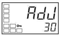
Input types 5, 7, 11, 12, 15:
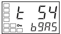
Input types 6, 8, 9, 10, 13, 14, 16, 17, 18, 19, 20, 21, 22, 24, 25:
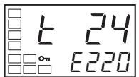
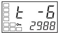
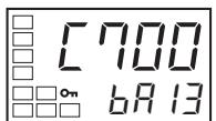
- Turn the power ON.
- Move to the calibration level.
This starts the 30-minute aging timer. This timer provides an approximate timer for aging. After 30 minutes have elapsed, the No. 2 display changes to 0. You can advance to the next step in this procedure even if 0 is not displayed.
- When the Key is pressed, the status changes as shown to the left.
The No. 2 display at this time shows the currently entered count value in hexadecimal. Set the STV as follows:
- Input types 5, 7, 11, 12, 15: Set to 54mV .
- Input types 6, 8, 9, 10, 13, 14, 16, 17, 18, 19, 20, 21, 22, 24, 25: Set to 24mV .
Allow the count value on the No. 2 display to fully stabilize, then press the Key to temporarily register the calibration settings.
If this count value is outside of the specified range, the No. 2 display will flash and the count value will not be temporarily registered.
- When the Key is pressed, the status changes as shown to the left.
Set the STV to -6mV
Allow the count value on the No. 2 display to fully stabilize, then press the Key to temporarily register the calibration settings.
If this count value is outside of the specified range, the No. 2 display will flash and the count value will not be temporarily registered.
- Press the l Key. The display changes as shown on the left. Set the STV to 700mV .
Allow the count value on the No. 2 display to fully stabilize, then press the Key to temporarily register the calibration settings.
If this count value is outside of the specified range, the No. 2 display will flash and the count value will not be temporarily registered.
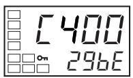
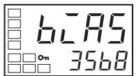
- Press the Key. The display changes as shown on the left. Set the STV to 400mV .
Allow the count value on the No. 2 display to fully stabilize, then press the Key to temporarily register the calibration settings. If this count value is outside of the specified range, the No. 2 display will flash and the count value will not be temporarily registered.
-
When the Key is pressed, the status changes as shown to the left.
-
Change the wiring as follows:
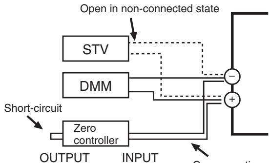
Compensating conductor of currently selected thermocouple.
Use K thermocouple compensating conductor for E, R, S, B, W, and PLII thermocouples and for an infrared temperature sensor.
Disconnect the STV to enable the thermocouple of the cold junction compensator. When doing this, be sure to disconnect the wiring on the STV side.
- Allow the count value on the No. 2 display to fully stabilize, then press the Key to temporarily register the calibration settings.
- When the Key is pressed, the status changes as shown to the left. The data to be temporarily registered is not displayed if it is not complete. Press the Key. The No. 2 display changes to yE . Release the key and wait two seconds or press the Key. This stores the temporarily registered calibration data to EEPROM. To cancel the saving of temporarily registered calibration data to EEPROM, press the Key (while N is displayed in the No. 2 display) without pressing the Key.
- The calibration mode is ended by turning the power OFF.
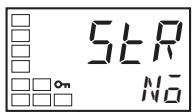
6-4 Platinum Resistance Thermometer Calibration (Thermocouple/Resistance Thermometer Input)
In this example, calibration is shown for Controller with a Thermocouple/ Resistance Thermometer Universal Input, with a resistance thermometer set as the input type.
Use connecting wires of the same thickness.
1,2,3... 1. Connect the power supply.
- Connect a precision resistance box (called a "6-dial" in this manual) to the platinum resistance thermometer input terminals, as shown in the following diagram.
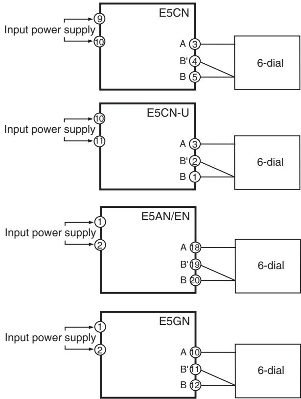
Input type 0:
Input types 1, 2, 3, 4:
3. Turn the power ON.
4. Move to the calibration level.
This starts the 30-minute aging timer. This timer provides an approximate timer for aging. After 30 minutes have elapsed, the No. 2 display changes to 0. You can advance to the next step in this procedure even if 0 is not displayed.
5. Execute calibration for the main input.
Press the Key to display the count value for each input type.
The No. 2 display at this time shows the currently entered count value in hexadecimal. Set the 6-dial as follows:
- Input type 0: 390Ω
- Input type 1, 2, 3 or 4: 280
Allow the count value on the No. 2 display to fully stabilize, then press the
Key to temporarily register the calibration settings.
If this count value is outside of the specified range, the No. 2 display will flash and the count value will not be temporarily registered.
Input type 0:
Input types 1, 2, 3, 4:
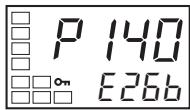
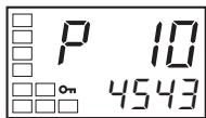
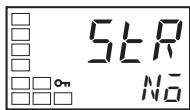
Press the Key to display the count value for each input type.
The No. 2 display at this time shows the currently entered count value in hexadecimal. Set the 6-dial as follows:
- Input type 0: 200Ω
- Input type 1, 2, 3 or 4: 140
Allow the count value on the No. 2 display to fully stabilize, then press the Key to temporarily register the calibration settings.
If this count value is outside of the specified range, the No. 2 display will flash and the count value will not be temporarily registered.
- When the Key is pressed, the status changes as shown to the left. Set the 6-dial to 10
Allow the count value on the No. 2 display to fully stabilize, then press the Key to temporarily register the calibration settings.
If this count value is outside of the specified range, the No. 2 display will flash and the count value will not be temporarily registered.
- When the Key is pressed, the status changes as shown to the left. The data to be temporarily registered is not displayed if it is not complete. Press the Key. The No. 2 display changes to yE5 . Release the key and wait two seconds or press the Key. This stores the temporarily registered calibration data to EEPROM.
To cancel the saving of temporarily registered calibration data to EEPROM, press the 回 Key (while N_ is displayed in the No. 2 display) without pressing the 回 Key.
- The calibration mode is quit by turning the power OFF.
6-5 Analog Input Calibration (Thermocouple/Resistance Thermometer Input)
In this example, calibration is shown for a Controller with a Thermocouple/ Resistance Thermometer Universal Input, with an analog input (0 to 50mV ) set as the input type.
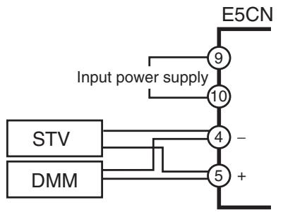
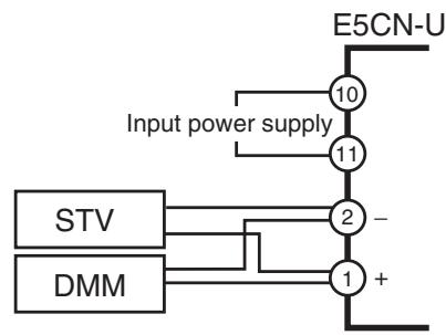
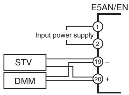
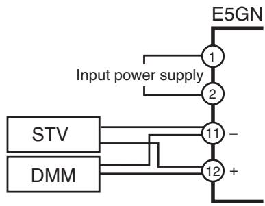
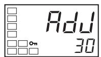
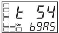
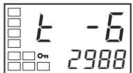
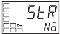
1,2,3... 1. Connect the power supply.
2. Connect an STV and DMM to the analog input terminals (same as thermocouple inputs), as shown in the figure above.
3. Turn the power ON.
4. Move to the calibration level. This starts the 30-minute aging timer. This timer provides an approximate timer for aging. After 30 minutes have elapsed, the No. 2 display changes to 0. You can advance to the next step in this procedure even if 0 is not displayed.
5. When the is pressed, the status changes as shown to the left. The No. 2 display at this time shows the currently entered count value in hexadecimal. Set the STV to 54mV .
Allow the count value on the No. 2 display to fully stabilize, then press the Key to temporarily register the calibration settings.
If this count value is outside of the specified range, the No. 2 display will flash and the count value will not be temporarily registered.
6. When the Key is pressed, the status changes as shown to the left. Set the STV to -6mV .
Allow the count value on the No. 2 display to fully stabilize, then press the Key to temporarily register the calibration settings.
If this count value is outside of the specified range, the No. 2 display will flash and the count value will not be temporarily registered.
7. When the Key is pressed, the status changes as shown to the left. The data to be temporarily registered is not displayed if it is not complete. Press the Key. The No. 2 display changes to yE5 . Release the key and wait two seconds or press the Key. This stores the temporarily registered calibration data to EEPROM.
To cancel the saving of temporarily registered calibration data to EEPROM, press the 回 Key (while N_ is displayed in the No. 2 display) without pressing the 回 Key.
8. The calibration mode is ended by turning the power OFF.
6-6 Calibrating Analog Input (Analog Input)
6-6-1 Calibrating a Current Input
In this example, calibration is shown for a Controller with an Analog Input, with a current input set as the input type.
1,2,3... 1. Connect the power supply.
2. Connect an STV and DMM to the current input terminals, as shown in the following diagram.
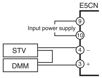
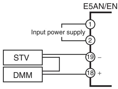
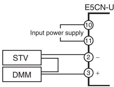
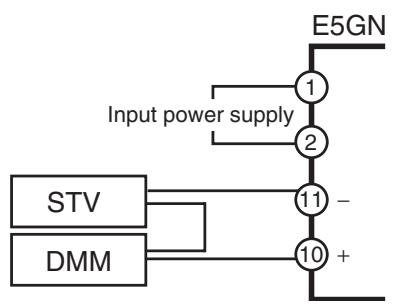
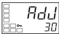
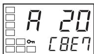
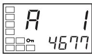
- Turn the power ON.
- Move to the calibration level.
This starts the 30-minute aging timer. This timer provides an approximate timer for aging. After 30 minutes have elapsed, the No. 2 display changes to 0. You can advance to the next step in this procedure even if 0 is not displayed.
- When the Key is pressed, the status changes as shown to the left.
The No. 2 display at this time shows the currently entered count value in hexadecimal. Set the STV to 20mA .
Allow the count value on the No. 2 display to fully stabilize, then press the Key to temporarily register the calibration settings.
If this count value is outside of the specified range, the No. 2 display will flash and the count value will not be temporarily registered.
- When the Key is pressed, the status changes as shown to the left.
Set the STV to 1mA .
Allow the count value on the No. 2 display to fully stabilize, then press the
Key to temporarily register the calibration settings.
If this count value is outside of the specified range, the No. 2 display will flash and the count value will not be temporarily registered.
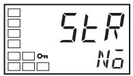
- When the Key is pressed, the status changes as shown to the left. The data to be temporarily registered is not displayed if it is not complete. Press the Key. The No. 2 display changes to 4E5 . Release the key and wait two seconds or press the Key. This stores the temporarily registered calibration data to EEPROM. To cancel the saving of temporarily registered calibration data to EE-PROM, press the Key (while N is displayed in the No. 2 display) without pressing the Key.
- The calibration mode is ended by turning the power OFF.
6-6-2 Calibrating a Voltage Input
In this example, calibration is shown for a Controller with an Analog Input, with a voltage input set as the input type.
1,2,3... 1. Connect the power supply.
2. Connect an STV and DMM to the voltage input terminals, as shown in the following diagram.
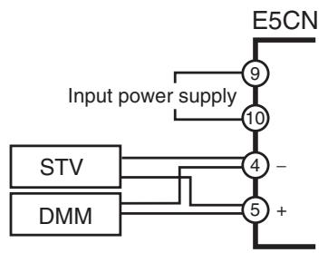
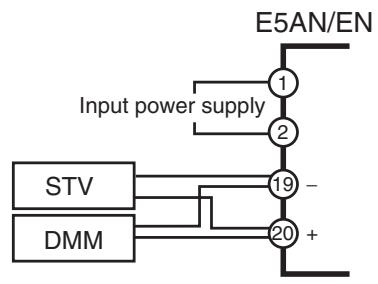
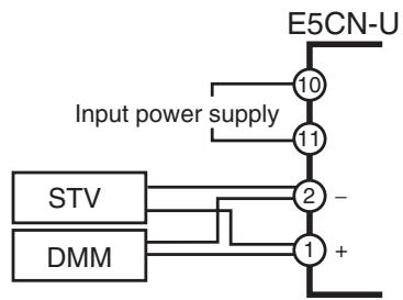
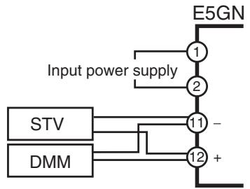
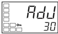
- Turn the power ON.
- Move to the calibration level.
This starts the 30-minute aging timer. This timer provides an approximate timer for aging. After 30 minutes have elapsed, the No. 2 display changes to 0. You can advance to the next step in this procedure even if 0 is not displayed.
- When the Key is pressed, the status changes as shown to the left.
The No. 2 display at this time shows the currently entered count value in hexadecimal. Set the STV as follows:
- Input type 2 or 3: 5V
- Input type 4: 10 ~V
Allow the count value on the No. 2 display to fully stabilize, then press the Key to temporarily register the calibration settings.
If this count value is outside of the specified range, the No. 2 display will flash and the count value will not be temporarily registered.
Input type 2 or 3:
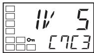
Input type 4:
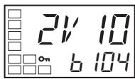
Input type 2 or 3:
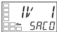
Input type 4:
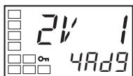
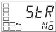
- When the Key is pressed, the status changes as shown to the left. Set the STV to 1 V.
Allow the count value on the No. 2 display to fully stabilize, then press the Key to temporarily register the calibration settings.
If this count value is outside of the specified range, the No. 2 display will flash and the count value will not be temporarily registered.
- When the Key is pressed, the status changes as shown to the left.
The data to be temporarily registered is not displayed if it is not complete. Press the Key. The No. 2 display changes to 4E5 . Release the key and wait two seconds or press the Key. This stores the temporarily registered calibration data to EEPROM.
To cancel the saving of temporarily registered calibration data to EEPROM, press the 回 Key (while N is displayed in the No. 2 display) without pressing the 回 Key.
- The calibration mode is ended by turning the power OFF.
6-7 Checking Indication Accuracy
- After calibrating the input, be sure to check the indication accuracy to make sure that the calibration has been executed correctly.
- Operate the E5CN/CN-U/AN/EN in the process value/set point monitor mode.
- Check the indication accuracy at the following three values: upper limit, lower limit, and mid-point.
6-7-1 Thermocouple or Infrared Temperature Sensor
- Preparations
The diagram below shows the required device connections. Make sure that the E5CN/CN-U/AN/EN/GN and cold junction compensator are connected by a compensating conductor for the thermocouple that is to be used during actual operation.
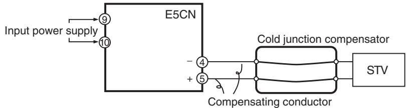
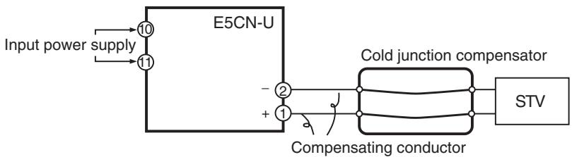
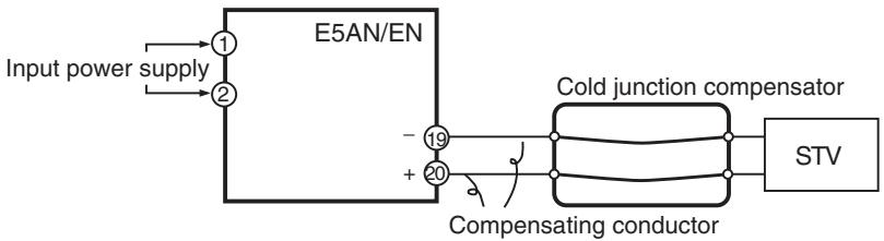
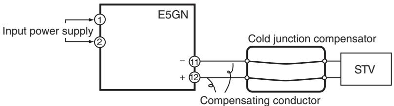
Operation
Make sure that the cold junction compensator is at 0^ , and set the STV output to the voltage equivalent of the starting power of the check value. The cold junction compensator and compensation conductor are not required when an external cold junction compensation method is used.
6-7-2 Platinum Resistance Thermometer
- Preparations
- The diagram below shows the required device connections.
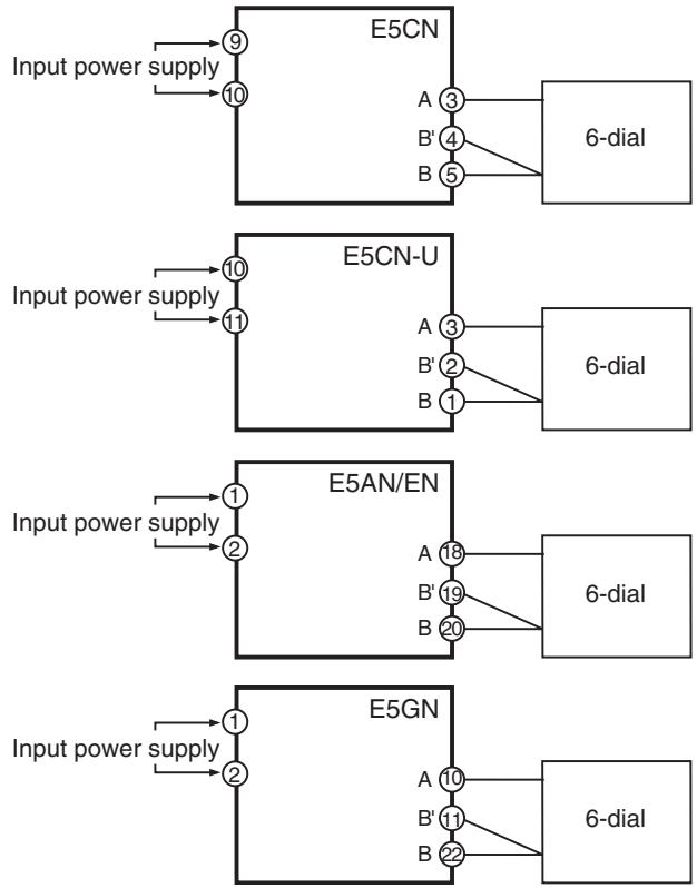
- Operation Set the 6-dial to the resistance equivalent to the check value.
6-7-3 Analog Input
- Preparations
The diagram below shows the required device connections.
(The connection terminals depend on the model and input type.)
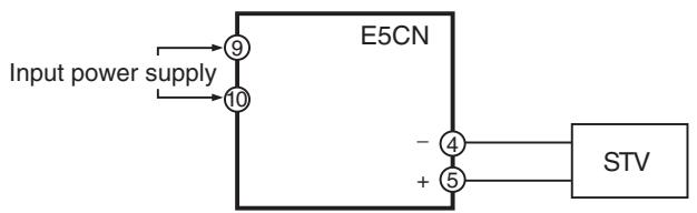
Controller with a Thermocouple/Resistance Thermometer Universal Input (Analog Input)
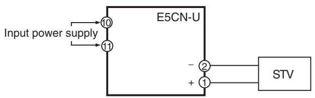
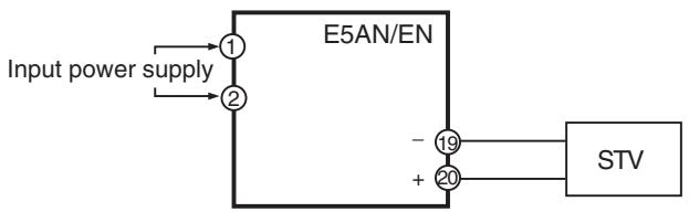
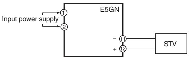
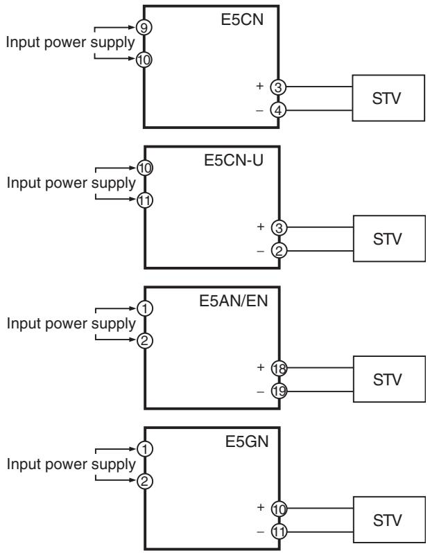
Current Input for a Controller with an Analog Input
Voltage Input for a Controller with an Analog Input
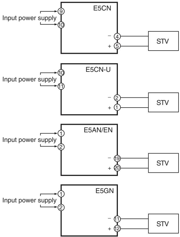
Operation
Set the STV output to the voltage or current equivalent to the check value.
Appendix
Specifications
Ratings
| Supply voltage | 100 to 240 VAC, 50/60 Hz | 24 VAC, 50/60 Hz/24 VDC | ||
| Operating voltage range | 85% to 110% of rated supply voltage | |||
| Power consumption | E5CN | 7.5 VA | 5 VA/3 W | |
| E5CN-U | 6 VA | 3 VA/2 W (4 VA/2 W for current output) | ||
| E5AN | 10 VA | 5.5 VA/4 W | ||
| E5EN | 10 VA | 5.5 VA/4 W | ||
| E5GN | 5.5 VA | 3 VA/2 W | ||
| Sensor input (See note 1.) | Temperature input typeThermocouple: K, J, T, E, L, U, N, R, S, B, W, PLIIPlatinum resistance thermometer: Pt100, JPt100Infrared temperature sensor: 10 to 70°C, 60 to 120°C, 115 to 165°C, 140 to 260°CVoltage input: 0 to 50 mV | |||
| Controllers with Analog Inputs (See note 2.)Current input: 4 to 20 mA, 0 to 20 mA (Input impedance: 150 Ω max.)Voltage input: 1 to 5 V, 0 to 5 V, 0 to 10 V (Input impedance: 1 MΩ max.) | ||||
| Control output | Relay output | E5CN | Relay output:SPST-NO, 250 VAC, 3 A (resistive load), electrical duality: 100,000 operationsMin. applicable load: 5 V, 10 mALong-life relay output (using a triac):SPST-NO, 250 VAC, 3 A (resistive load), electrical duality: 1,000,000 operationsLoad power supply voltage: 75 to 250 VAC (See note 3.)Leakage current: 5 mA max. (250 VAC, 60 Hz) | |
| E5CN-U | SPDT, 250 VAC, 3A (resistive load), electrical durability: 100,000 operationsMin. applicable load 5 V 10 mA | |||
| E5AN | Relay output:SPST-NO, 250 VAC, 5 A (resistive load), electrical duality: 100,000 operationsMin. applicable load: 5 V, 10 mA | |||
| E5EN | Long-life relay output (using a triac):SPST-NO, 250 VAC, 3 A (resistive load), electrical duality: 1,000,000 operationsLoad power supply voltage: 75 to 250 VAC (See note 3.)Leakage current: 5 mA max. (250 VAC, 60 Hz) | |||
| E5GN | SPST-NO, 250 VAC, 2 A (resistive load), electrical durability: 100,000 operations,Min. applicable load: 5 V, 10 mA | |||
| Voltage output | E5CN | Output voltage 12 VDC ±15% (PNP), max. load current 21 mA, with short-circuit protection circuit | ||
| E5AN | Output voltage 12 VDC ±15% (PNP), max. load current 40 mA, with short-circuit protection circuit | |||
| E5EN | Note Control output 2: 12 VDC ±15% (PNP), max. load current 21 mA, with short-circuit protection circuit | |||
| E5GN | Output voltage 12 VDC ±15% (PNP), max. load current 21 mA, with short-circuit protection circuit | |||
| Current output | 4 to 20 mA DC, 0 to 20 mA DC, Load: 500 Ω max. for E5GN and 600 Ω max. for other models, Resolution: Approx. 10,000 | |||
| Auxiliary output | E5CN E5CN-U | SPST-NO, 250 VAC, 3 A (resistive load), electrical durability: 100,000 operations Min. applicable load: 5 V, 10 mA | ||
| E5AN E5EN | SPST-NO, 250 VAC, 3 A (resistive load), electrical durability: 100,000 operations Min. applicable load: 5 V, 10 mA | |||
| E5GN | SPST-NO, 250 VAC, 2 A (resistive load), electrical durability: 100,000 operations, Min. applicable load: 5 V, 10 mA | |||
| Control method | 2-PID or ON/OFF control | |||
| Setting method | Digital setting using front panel keys | |||
| Indication method | 11-segment/7-segment digital display and single-lighting indicator | |||
| Other functions | Depend on the model | |||
| Ambient temperature | -10 to 55°C (with no condensation or icing); with 3-year guarantee: -10 to 50°C | |||
| Ambient humidity | 25% to 85% | |||
| Storage temperature | -25 to 65°C (with no condensation or icing) | |||
| Altitude | 2,000 m or less | |||
| Recommended fuse | T2A, 250 VAC, time lag, low shut-off capacity | |||
| Installation environment | Installation Category II, Pollution Class 2 (IEC 61010-1 compliant) | |||
Note (1) For the setting ranges for each sensor input, see page 303.
(2) When connecting the ES2-THB, connect it 1:1.
(3) Always connect an AC load to a long-life relay output. The output will not turn OFF if a DC load is connected, because a triac is used for switching when closing and opening the circuit.
HB, HS, and Heater Overcurrent Alarms (for E5CN/AN/EN/GN Controllers with Heater Burnout, HS, and Heater Overcurrent Alarms)
| Max. heater current | 50 A AC |
| Input current readout accuracy | ±5% FS ±1 digit max. |
| Heater burnout alarm setting range | 0.1 to 49.9 A (0.1 A units)0.0 A: Heater burnout alarm output turns OFF.50.0 A: Heater burnout alarm output turns ON.Min. detection ON time: 100 ms (See note 1.) |
| HS alarm setting range | 0.1 to 49.9 A (0.1 A units)0.0 A: HS alarm output turns ON.50.0 A: HS alarm output turns OFF.Min. detection OFF time: 100 ms (See note 2.) |
| Heater overcurrent alarm setting range | 0.1 to 49.9 A (0.1 A units)0.0 A: Heater overcurrent alarm output turns ON.50.0 A: Heater overcurrent alarm output turns OFF.Min. detection OFF time: 100 ms |
Note (1) When the control output 1 ON time is less than 100ms , heater burnout detection, heater overcurrent detection, and heater current measurement are not performed.
(2) When the control output 1 OFF time is less than 100ms , HS alarm, and leakage current measurement are not performed.
External Power Supply for ES1B
| Output voltage | 12 VDC ±10% |
| Output current | 20 mA max. |
Note Contact your OMRON representative for information on using the external power supply for ES1B for other applications.
Characteristics
| Indication accuracy(ambient temperature of 23°C) | Thermocouple (See note 1.):E5CN/AN/EN/GN: (±0.3% of PV or ±1°C, whichever is greater) ±1 digit max.E5CN-U: (±1% of PV or ±2°C, whichever is greater) ±1 digit max.Platinum resistance thermometer:(±0.2% of PV or ±0.8°C, whichever is greater) ±1 digit max.Analog input: ±0.2% FS ±1 digit max.CT input: ±5% FS ±1 digit max. | |||
| Temperature variation influence (See note 2.) | Thermocouple (R, S, B, W, PLII)E5CN/AN/EN/GN: (±1% of PV or ±10°C, whichever is greater) ±1 digit max.E5CN-U: (±2% of PV or ±10°C, whichever is greater) ±1 digit max.Other thermocouples:E5CN/AN/EN/GN: (±1% of PV or ±4°C, whichever is greater) ±1 digit max.E5CN-U: (±2% of PV or ±4°C, whichever is greater) ±1 digit max.*K thermocouple at -100°C max: ±10°C max.Platinum resistance thermometer:(±1% of PV or ±2°C, whichever is greater) ±1 digit max.Analog input: ±1% FS ±1 digit max.CT input: ±5% FS ±1 digit max. | |||
| Voltage variation influence (See note 2.) | Controllers with Thermocouple/Resistance Thermometer Universal Inputs | 0.1 to 999.9°C or °F(in units of 0.1°C or °F) (See note 3.) | ||
| Controllers with Analog Inputs | 0.01% to 99.99% FS (in units of 0.01% FS) | |||
| Hysteresis | Controllers with Thermocouple/Resistance Thermometer Universal Inputs | 0.1 to 999.9°C or °F(in units of 0.1 EU) (See note 3.) | ||
| Controllers with Analog Inputs | 0.1% to 999.9% FS (in units of 0.1% FS)0.01% to 99.99% FS (in units of 0.01% FS) | |||
| Integral time (I) | 0 to 3,999 s (in units of 1 s) | |||
| Derivative time (D) | 0 to 3,999 s (in units of 1 s)When RT is ON: 0.0 to 999.9 (in units of 0.1 s) | |||
| Control Period | 0.5, 1 to 99 s (in units of 1 s) | |||
| Manual reset value | 0.0% to 100.0% (in units of 0.1%) | |||
| Alarm setting range | -1,999 to 9,999 (decimal point position depends on input type) | |||
| Sampling period | 250 ms | |||
| Insulation resistance | 20 MΩ min. (at 500 VDC) | |||
| Dielectric strength | 2,300 VAC, 50/60 Hz for 1 min between terminals of different charge | |||
| Malfunction vibration | 10 to 55 Hz, 20 m/s2for 10 min each in X, Y and Z directions | |||
| Vibration resistance | 10 to 55 Hz, 20 m/s2for 2 hr each in X, Y, and Z directions | |||
| Malfunction shock | 100 m/s2, 3 times each in X, Y, and Z directions | |||
| Shock resistance | 300 m/s2, 3 times each in X, Y, and Z directions | |||
| Weight | E5CN | Approx. 150 g | Adapter: approx. 10 g | Terminal cover: approx. 10 g |
| E5CN-U | Approx. 110 g | --- | ||
| E5AN | Approx. 310 g | Adapter: approx. 100 g | Terminal cover: approx. 1.6 g per cover | |
| E5EN | Approx. 260 g | |||
| E5GN | Approx. 90 g | Adapter: approx. 10 g | --- | |
| Degree of protection | E5CN | Front panel: IP66 | ||
| E5AN | Rear case: IP20 | |||
| E5EN | Terminals: IP00 | |||
| E5GN | Front panel: IP50, rear case: IP20, terminals: IP00 | |||
| Memory protection | EEPROM (non-volatile memory) (number of writes: 1,000,000) | |||
Note
(1) The indication accuracy of K thermocouples in the -200 to 1,300^ range, T and N thermocouples at a temperature of -100^ or less, and U and L thermocouples at any temperature is ± 2^ ± 1 digit maximum. The indication accuracy of B thermocouples at a temperature of 400^ to 800 ± 3^ or less is not specified. The indication accuracy of R and S thermocouples at a temperature of 200^ or less is ± 3^ ± 1 digit maximum. The indication accuracy of W thermocouples is (the larger of ± 0.3% or ± 3^ ) ± 1 digit maximum and the indication accuracy of PLL thermocouples is (the larger of ± 0.3% or ± 2^ ) ± 1 digit maximum.
(2) Ambient temperature: -10^ to 23^ to 55^ Voltage range: -15 to +10% of rated voltage
(3) Set "None" as the unit for Controllers with Analog Inputs.
Rating and Characteristics of Options
| Event inputs | Contact Input ON: 1 kΩ max., OFF: 100 kΩ min. |
| Non-contact Input ON: Residual voltage 1.5 V max.; OFF: Leakage current 0.1 mA max. | |
| Communications | Transmission path: RS-485/232C Communications method: RS-485 (2-wire, half duplex) or RS-232C Synchronization: Start-stop Baud rate: 1.2, 2.4, 4.8, 9.6, 19.2, 38.4, or 57.6 kbps |
| Transfer output | 4 to 20 mA DC, Load: 600 Ω max., Resolution: 10,000, Accuracy: ±0.3% |
Waterproof Packing
If the Waterproof Packing is lost or damage, order one of the following models.
| Y92S-29 (for DIN 48 × 48) | Y92S-P4 (for DIN 96 × 96) |
| Y92S-32 (for DIN 48 × 24) | Y92S-P4 (for DIN 48 × 96) |
Current Transformer (CT)
Specifications
| Item | Specifications | |
| Model number | E54-CT1 | E54-CT3 |
| Max. continuous current | 50 A | 120 A (See note.) |
| Dielectric strength | 1,000 VAC (for 1 min) | |
| Vibration resistance | 50 Hz, 98 m/s2 | |
| Weight | Approx. 11.5 g | Approx. 50 g |
| Accessories | None | Armature (2), Plug (2) |
Note The maximum continuous current of the E5□N is 50 A.
External Dimensions
E54-CT1
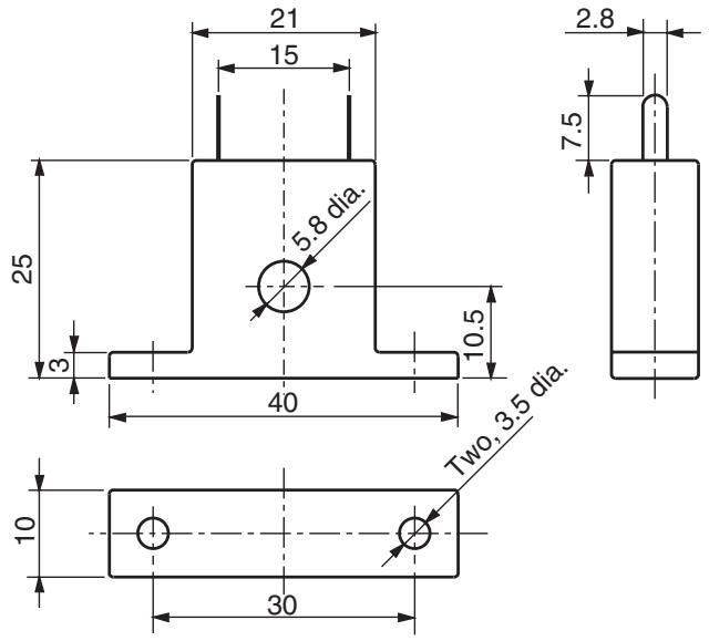
E54-CT3
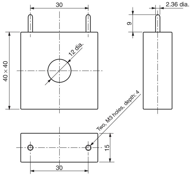
E58-CIFQ1 USB-Serial Conversion Cable
Specifications
| Item | Specifications |
| Applicable OS | Windows 2000/XP/Vista |
| Applicable software | CX-Thermo |
| Applicable models | OMRON E5AN/EN/CN/CN-U/GN Digital Temperature Control- lers |
| USB interface rating | Conforms to USB Specification 1.1 |
| DTE speed | 38,400 bps |
| Connector specifications | Computer end: USB (type A plug)Temperature Controller end: Serial |
| Power supply | Bus power (5 VDC supplied from USB host controller) |
| Current consumption | 70 mA |
| Ambient operating temperature | 0 to 55°C (with no condensation or icing) |
| Ambient operating humidity | 10% to 80% |
| Storage temperature | -20 to 60°C (with no condensation or icing) |
| Storage humidity | 10% to 80% |
| Altitude | 2,000 m max. |
| Weight | Approx. 100 g |
Compatible Operating Environment
A personal computer that includes the following specifications is required.
- USB port
- CD-ROM drive
- Windows 2000/XP/Vista
Appearance and Nomenclature
Appearance

LED Indicator Display
| Indicator | Color | Status | Meaning |
| SD | Yellow | Lit | Sending data from USB-Serial Conversion Cable |
| Not lit | Not sending data from USB-Serial Conversion Cable | ||
| RD | Yellow | Lit | Receiving data from the USB-Serial Conversion Cable |
| Not lit | Not receiving data from the USB-Serial Conversion Cable |
Error Displays
When an error occurs, the error contents are shown on the No. 1 or the No. 2 display.
This section describes how to check error codes on the display, and the actions to be taken to remedy the problems.
5.ERR
Input Error
Meaning
The input value has exceeded the control range. (See note.)
The input type setting is not correct.
The sensor is disconnected or shorted.
The sensor wiring is not correct.
The sensor is not wired.
Note Control Range
Resistance thermometer, thermocouple input: Temperature setting lower limit -20^ to temperature setting upper limit +20^
(Temperature setting lower limit -40^ to temperature setting upper limit +40^ )
ES1B input: Same as input indication range
Analog input -5% to +105% of scaling range
Action
Check the wiring of inputs for miswiring, disconnections, and short-circuits and check the input type.
If no abnormality is found in the wiring and input type, turn the power OFF then back ON again.
If the display remains the same, the Controller must be replaced. If the display is restored, then the probable cause is electrical noise affecting the control system. Check for electrical noise.
Note With resistance thermometer input, a break in the A, B, or B' line is regarded as a disconnection.
Operation at Error
After an error occurs, the error is displayed and the alarm outputs function as if the upper limit has been exceeded.
When the Input Error Output parameter in the advanced function setting level is set to ON, the output assigned to the alarm 1 function turns ON whenever an input error occurs.
An error message is displayed when the PV, PV/SP, or PV/MV is displayed.
Note The control output turns OFF. When the manual MV, MV at stop, or MV at PV error is set, however the control output corresponds to the set value.
CCCCC
Display Range Exceeded
Meaning
Though this is not an error, it is displayed if the process value exceeds the display range when the control range is larger than the display range.
The display ranges are shown below (with decimal points omitted).
- When less than -1,999 C C C
- When more than 9,999
Action
Control continues, allowing normal operation. The message is displayed when the PV, PV/SP, or PV/MV is displayed.
Resistance thermometer input (Except for models with a setting range of -199.9 to 500.0^
Thermocouple input (Except for models with a setting range of -199.9 to 400.0^ )
| ES1B Control range | ||
| 5.ERR display | Numeric display | 5.ERR display |
| Input indication range | ||
Resistance thermometer input (Except for models with a setting range of -1999 to 500.0^
Thermocouple input (Except for models with a setting range of -199.9 to 400.0^ )
| 5.ERR display | cccc display | Numeric display | 5.ERR display |
| Input indication range |
Analog Input
- When display range < control range
| Control range | |||
| S. ERR display | c c c c display | Numeric display | d d d d display |
| Input indication range | |||
| -1999←Display range→9999(See note.) | |||
Analog Input
- When display range > control range
| Control range | ||
| 5.ERR display | Numeric display | 5.ERR display |
| -1999←Display range→9999 (See note.) | ||
Note: The display range is shown in numbers with decimal points omitted.
E333
AD Converter Error
Meaning
There is an error in internal circuits.
Action
First, turn the power OFF then back ON again. If the display remains the same, the Controller must be repaired. If the display is restored, then the probable cause is electrical noise affecting the control system. Check for electrical noise.
Operation
Control output and alarm output turn OFF.
E E E
Memory Error
Meaning
Internal memory operation is in error.
Action
First, turn the power OFF then back ON again. If the display remains the same, the Controller must be repaired. If the display is restored, then the probable cause is electrical noise affecting the control system. Check for electrical noise.
Operation at Error
Control output and alarm output turn OFF. (Current output is approx. 0mA ).
FFFF
Current Value Exceeds
Meaning
This error is displayed when the heater current value exceeds 55.0 A.
Action
Control continues, allowing normal operation. An error message is displayed when the following items are displayed.
Heater current 1 value monitor
Heater current 2 value monitor
Leakage current 1 monitor
Leakage current 2 monitor
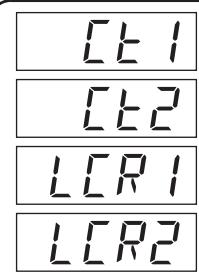
Heater Burnout
HS Alarm
Heater Overcurrent
Meaning
When heater burnout, HS alarm, or heater overcurrent occurs, the No. 1 display in the applicable setting level flashes.
Action
When a heater burnout, HS error, or heater overcurrent is detected, the HA indicator lights and the No. 1 display flashes for the applicable Heater Current 1 Value Monitor, Heater Current 2 Value Monitor, Leakage Current 1 Monitor, or Leakage current 2 Monitor parameters in the operation level and adjustment level. Control continues, allowing normal operation.
Troubleshooting
Checking Problems
If the Temperature Controller is not operating normally, check the following points before requesting repairs. If the problem persists, contact your OMRON representative for details on returning the product.
| Timing | Status | Meaning | Countermeasures | Page |
| Turning ON the power for the first time | Temperature unit (°C/F) is flashing. | ST (self-tuning) is in progress (default setting: ON). | This is not a product fault. The temperature unit (°C/F) flashes while ST (self-tuning) is being performed | 64 |
| Temperature error is large. Input error (S.Err display) | Input type mismatch | Check the sensor type and reset the input type correctly. | 52 | |
| Thermometer is not installed properly. | Check the thermometer installation location and polarity and install correctly. | 31 | ||
| Communications are not possible. | Non-recommended adapter is being used. | Make sure that the connected device is not faulty. | Section 1 of Communications Manual | |
| Communications are not possible. | Non-recommended adapter is being used. | Make sure that the connected device is not faulty. | (See note.) | |
| During operation | Overshooting Undershooting Hunting | ON/OFF control is enabled (default: ON/OFF control selected). | Select PID control and execute either ST (self-tuning) or AT (auto-tuning). When using self-tuning, turn ON the power supply to the Temperature Controller and load (heater, etc.) at the same time, or turn ON the load power supply first. Accurate self-tuning and optimum control will not be possible if the power supply to the load is turned ON after turning ON the power supply to the Temperature Controller. | 62 |
| Control cycle is longer compared with the speed of rise and fall in temperature | Shorten the control cycle. A shorter control cycle improves control performance, but a cycle of 20 ms minimum is recommended in consideration of the service life of the relays. | 54 | ||
| Unsuitable PID constant | Set appropriate PID constants using either of the following methods. • Execute AT (autotuning). • Set PID constants individually using manual settings. | 62 | ||
| HS alarm operation fault | Use breeder resistance if the problem is due to leakage current. Also investigate the errors detected by the HS alarm function. | 54 | ||
| Temperature is not rising | Specified operation is unsuitable for required control (default: Reverse operation) | Select either forward or reverse operation depending on the required control. Reverse operation is used for heating operations. | 54 | |
| Heater is burnt out or deteriorated. | Check whether heater burnout or deterioration have occurred. Also investigate the errors detected by the heater burnout alarm. | 54 | ||
| Insufficient heater capacity | Check whether the heater's heating capacity is sufficient. | --- | ||
| Cooling system in operation. | Check whether a cooling system is operating. | --- | ||
| Peripheral devices have heat prevention device operat-ing. | Set the heating prevention temperature setting to a value higher than the set temperature of the Temperature Controller. | --- |
Note Refer to the E5CN/E5AN/E5EN/E5GN Digital Temperature Controller Communications Manual (Cat. No. H158) for details.
| Timing | Status | Meaning | Countermeasures | Page |
| During operation (continued) | Output will not turn ON | Set to STOP (default: RUN) | Set the RUN/STOP mode to RUN. If STOP is lit on the display, control is stopped. | 172 |
| Specified operation is unsuitable for required control (default: Reverse operation) | Select either forward or reverse operation depending on the required control. Reverse operation is used for heating operations. | 54 | ||
| A high hysteresis is set for ON/OFF operation (default: 1.0°C) | Set a suitable value for the hysteresis. | 60 | ||
| Temperature Controller will not operate | Set to STOP (default: RUN) | Set the RUN/STOP mode to RUN. If STOP is lit on the display, control is stopped. | 172 | |
| Temperature error is large Input error (S.err dis-play) | Thermometer has burnt out or short-circuited. | Check whether the thermometer has burnt out or short-circuited | --- | |
| Thermometer lead wires and power lines are in the same conduit, causing noise from the power lines (generally, display values will be unstable). | Wire the lead wires and power lines in separate conduits, or wiring using a more direct path. | --- | ||
| Connection between the Temperature Controller and thermocouple is using copper wires. | Connect the thermocouple's lead wires directly, or connect a compensating conductor suitable for the thermocouple. | --- | ||
| Installation location of thermometer is unsuitable. | Check whether the location of the thermometer is suitable. | --- | ||
| Input shift is not set correctly (default: 0°C) | Set a suitable input shift. If input shift is not required, set the input shift value to 0.0. | 89 | ||
| Keys will not operate | Setting change protect is ON. | Turn OFF setting change protect. | 110 | |
| Cannot shift levels | Operations limited due to protection. | Set the operation/adjustment protect, initial setting/communications protect, and setting change protect values as required. | 110 | |
| After long service life | Control is unstable | Terminal screws may be loose. | Retighten terminal screws to a torque of 0.74 to 0.90 N·m (see note). | 33 |
| The internal components have reached the end of their service life. | The Temperature Controller's internal electrolytic capacitor depends on the ambient temperature, and load rate. The structural life depends on the ambient environment (shock, vibration). The life expectancy of the output relays varies greatly with the switching capacity and other switching conditions. Always use the output relays within their rated load and electrical life expectancy. If an output relay is used beyond its life expectancy, its contacts may become welded or burned. Replace the Temperature Controller and all other Temperature Controllers purchased in the same time period. | --- |
Note The tightening torque is 0.5N· m for the E5CN-U and 0.43 to 0.58N· m for the E5GN. The terminal torque is 0.5 to 0.6N· m for auxiliary output 2 on the E5GN.
Symptom: Cannot Communicate or a Communications Error Occurs
| Meaning | Countermeasures |
| The communications wiring is not correct. | Correct the wiring. |
| The communications line has become dis- connected. | Connect the communications line securely and tighten the screws. |
| The communications cable is broken. | Replace the cable. |
| The communications cable is too long. | The total cable length is 500 m maximum for RS-485 and 15 m maximum for RS-232C communications. To extend the communications distance for RS-232C communications, use OMROM's Z3R Optical Interface. |
| The wrong communications cable has been used. | E5CN, E5EN, or E5AN: Use a shielded, AWG24 to AWG14 (cross-sec-tional area of 0.205 to 2.081 mm2) twisted-pair cable for the communica-tions cable. E5GN: Use a shielded, AWG24 to AWG18 (cross-sectional area of 0.205 to 0.823 mm2) twisted-pair cable for the communications cable. |
| More than the specified number of communi-cations devices are connected to the same communications path for RS-485 communi-cations. | When 1:N RS-485 communications are used, a maximum of 32 nodes (including the host node) can be connected. |
| An end node has not been set at each end of the communications line for RS-485 communi-cations. | Set or connect terminating resistance at each end of the line. If the E5CN, E5AN, E5EN, or E5GN is the end node, use 120-Ω (1/2-W) terminating resistance. The combined terminating resistance with the host device must be at least 54 Ω. |
| The specified power supply voltage is not being supplied to the Controller. | Supply the specified power supply voltage. |
| The specified power supply voltage is not being supplied to an Interface Converter (such as the K3SC). | Supply the specified power supply voltage. |
| The same baud rate and communications method are not being used by all of the Con-trolers, host devices, and other devices on the same communications line. | Set the same values for the baud rate, protocol, data length, stop bits, and parity on all nodes. |
| The unit number specified in the command frame is different from the unit number set by the Controller. | Use the same unit number. |
| The same unit number as the Controller is being used for another node on the same communications line for RS-485 communica-tions. | Set each unit number for only one node. |
| There is a mistake in programming the host device. | Use a line monitor to check the commands. Check operation using a sam-ple program. |
| The host device is detecting the absence of a response as an error before it receives the response from the Controller. | Shorten the send data wait time in the Controller or increase the response wait time in the host device. |
| The host device is detecting the absence of a response as an error after broadcasting a command (except for SYSWAY). | The Controller does not return responses for broadcast commands. |
| The host device sent another command before receiving a response from the Control-ler. | The response must always be read after sending a command (except for broadcast commands). |
| The host device sent the next command too soon after receiving a response from the Controller. | After receiving a response, wait at least 2 ms before sending the next command. |
| The communications line became unstable when Controller power was turned ON or interrupted, and the host device read the unstable status as data. | Initialize the reception buffer in the host device before sending the first command and after turning OFF the power to the Controller. |
| The communications data was corrupted from noise from the environment. | Try using a slower baud rate.Separate the communications cable from the source of noise.Use a shielded, twisted-pair cable for the communications cable.Use as short a communications cable as possible, and do not lay or loop extra cable.To prevent inductive noise, do not run the communications cable parallel to a power line.If noise countermeasures are difficult to implement, use an Optical Inter-face. |
Note For details on errors, refer to E5CN/E5AN/E5EN/E5GN Digital Temperature Controllers Communications Manual Basic Type (Cat. No. H158).
Parameter Operation Lists
Universal input: Controllers with Thermocouple/Resistance Thermometer Universal Inputs
Analog input: Controllers with Analog Inputs
Operation Level
| Parameters | Characters | Setting (monitor) value | Display | Default | Unit | Set value |
| Process Value | Temperature: According to indication range for each sensor. Analog: Scaling lower limit -5% FS to Scaling upper limit +5% FS | EU | ||||
| Set Point | SP lower limit to SP upper limit | 0 | EU | |||
| Auto/Manual Switch | R-M | |||||
| Multi-SP Set Point Setting | M-SP | 0 to 3 | 0 | None | ||
| Set Point During SP Ramp | SP-M | SP lower limit to SP upper limit | EU | |||
| Heater Current 1 Value Monitor | Ct-I | 0.0 to 55.0 | A | |||
| Heater Current 2 Value Monitor | Ct-II | 0.0 to 55.0 | A | |||
| Leakage Current 1 Monitor | LCRI | 0.0 to 55.0 | A | |||
| Leakage Current 2 Monitor | LCR2 | 0.0 to 55.0 | A | |||
| Program Start | PRST | RSET, STRT | RSET, SRTRE | RSET | None | |
| Soak Time Remain | SskTR | 0 to 9999 | min or h | |||
| RUN/STOP | R-S | RUN/STOP | RUN, Stap | Run | None | |
| Alarm Value 1 | RL-I | -1999 to 9999 | 0 | EU | ||
| Alarm Value Upper Limit 1 | RL IH | -1999 to 9999 | 0 | EU | ||
| Alarm Value Lower Limit 1 | RL IL | -1999 to 9999 | 0 | EU | ||
| Alarm Value 2 | RL-J | -1999 to 9999 | 0 | EU | ||
| Alarm Value Upper Limit 2 | RL2H | -1999 to 9999 | 0 | EU | ||
| Alarm Value Lower Limit 2 | RL2L | -1999 to 9999 | 0 | EU | ||
| Alarm Value 3 | RL-J3 | -1999 to 9999 | 0 | EU | ||
| Alarm Value Upper Limit 3 | RL3H | -1999 to 9999 | 0 | EU | ||
| Alarm Value Lower Limit 3 | RL3L | -1999 to 9999 | 0 | EU | ||
| MV Monitor (Heating) | a | -5.0 to 105.5 (standard) 0.0 to 105.0 (heating/cooling) | % | |||
| MV Monitor (Cooling) | c-a | 0.0 to 105.0 | % |
Adjustment Level
| Parameters | Characters | Setting (monitor) value | Display | Default | Unit | Set value |
| Adjustment Level Display | L.Rdu | |||||
| AT Execute/Cancel | Rt | OFF, AT CancelAT-2: 100%AT ExecuteAT-1: 40%AT Execute | aFF, Rt-2, Rt-1 | OFF | None | |
| Communications Writing | CMHc | OFF, ON | aFF, aN | OFF | None | |
| Heater Current 1 Value Monitor | Ct I | 0.0 to 55.0 | A | |||
| Heater Burnout Detection 1 | Hb I | 0.0 to 50.0 | 0.0 | A | ||
| Heater Overcurrent Detection 1 | aC I | 0.0 to 50.0 | 50.0 | A | ||
| Heater Current 2 Value Monitor | Ct2 | 0.0 to 55.0 | A | |||
| Heater Burnout Detection 2 | Hb2 | 0.0 to 50.0 | 0.0 | A | ||
| Heater Overcurrent Detection 2 | aC2 | 0.0 to 50.0 | 50.0 | A | ||
| Leakage Current 1 Monitor | LCR I | 0.0 to 55.0 | A | |||
| HS Alarm 1 | HS I | 0.0 to 50.0 | 50.0 | A | ||
| Leakage Current 2 Monitor | LCR2 | 0.0 to 55.0 | A | |||
| HS Alarm 2 | HS2 | 0.0 to 50.0 | 50.0 | A | ||
| SP 0 | SP-0 | SP lower limit to SP upper limit | 0 | EU | ||
| SP 1 | SP-1 | SP lower limit to SP upper limit | 0 | EU | ||
| SP 2 | SP-2 | SP lower limit to SP upper limit | 0 | EU | ||
| SP 3 | SP-3 | SP lower limit to SP upper limit | 0 | EU | ||
| Temperature Input Shift | cNS | -199.9 to 999.9 | 0.0 | °C or °F | ||
| Upper Limit Temperature Input Shift Value | cNSH | -199.9 to 999.9 | 0.0 | °C or °F | ||
| Lower Limit Temperature Input Shift Value | cNSL | -199.9 to 999.9 | 0.0 | °C or °F | ||
| Proportional Band | P | Universal input: 0.1 to 999.9 | 8.0 | °C or °F(See note 1.) | ||
| Analog input: 0.1 to 999.9 | 10.0 | %FS | ||||
| Integral Time | c | 0 to 3,999 | 233 | Second | ||
| Derivative Time | d | RT OFF: 0 to 3,999 | 40 | Second | ||
| RT ON: 0.0 to 999.9 | 40.0 | Second | ||||
| Cooling Coefficient | C-5C | 0.01 to 99.99 | 1.00 | None | ||
| Dead Band | C-db | Universal input: -199.9 to 999.9 | 0.0 | °C or °F(See note 1.) | ||
| Analog input: -19.99 to 99.99 | 0.00 | %FS | ||||
| Manual Reset Value | aF-R | 0.0 to 100.0 | 50.0 | % | ||
| Hysteresis (Heating) | HYS | Universal input: 0.1 to 999.9 | 1.0 | °C or °F(See note1.) | ||
| Analog input: 0.01 to 99.99 | 0.10 | %FS | ||||
| Hysteresis (Cooling) | CHYS | Universal input: 0.1 to 999.9 | 1.0 | °C or °F(See note1.) | ||
| Analog input: 0.01 to 99.99 | 0.10 | %FS | ||||
| Soak Time | SBRK | 1 to 9,999 | 1 | min or h | ||
| Wait Band | Wt-b | Universal input: OFF, 0.1 to 999.9 | aFF, 0.1 to 999.9 | OFF | °C or °F(See note1.) | |
| Analog input: OFF, 0.01 to 99.99 | aFF, 0.01 to 99.99 | OFF | %FS | |||
| MV at Stop | MV-5 | -5.0 to 105.0 (standard)-105.0 to 105.0 (heating/cool-ing) | 0.0 | % | ||
| MV at PV Error | MV-E | -5.0 to 105.0 (standard)-105.0 to 105.0 (heating/cool-ing) | 0.0 | % | ||
| SP Ramp Set Value | SPRE | OFF or 1 to 9,999 | aFF, 1 to 9999 | OFF | EU/s, EU/min, EU/h | |
| MV Upper Limit | aL-H | MV lower limit +0.1 to 105.0(standard)0.0 to 105.0 (heating/cooling) | 105.0 | % | ||
| MV Lower Limit | aL-L | -5.0 to MV upper limit -0.1(standard)-105.0 to 0.0 (heating/cool-ing) | -5.0 (standard)-105.0 (heating/cooling) | % | ||
| MV Change RateLimit | aRL | 0.0 to 100.0(0.0: MV Change Rate LimitDisabled) | 0.0 | %/s | ||
| Extraction of SquareRoot Low-cut Point | SGRP | 0.0 to 100.0 | 0.0 | % |
Initial Setting Level
| Parameters | Characters | Setting (monitor) value | Display | Default | Unit | Set value | ||
| Input Type | \(\underline{\mathsf{CN}}-\underline{\mathsf{c}}\) | Multi-input | 0: Pt1001: Pt1002: Pt1003: JPt1004: JPt100 | 5 | None | |||
| 5: K6: K7: J8: J9: T10: T11: E12: L13: U14: U15: N16: R17: S18: B19: 10 to 70°C20: 60 to 120°C21: 115 to 165°C22: 160 to 260°C23: 0 to 50 mV24: W25: PLII | ||||||||
| Analog input | 0: 4 to 20 mA1: 0 to 20 mA2: 1 to 5 V3: 0 to 5 V4: 0 to 10 V | 0 | None | |||||
| Scaling Upper Limit | \(\underline{\mathsf{CN}}-\underline{\mathsf{h}}\) | Scaling lower limit + 1 to 9,999 | 100 | None | ||||
| Scaling Lower Limit | \(\underline{\mathsf{CN}}-\underline{\mathsf{L}}\) | -1,999 to scaling upper limit -1 | 0 | None | ||||
| Decimal Point | \(d^P\) | Universal input: 0 to 1 | 0 | None | ||||
| Analog input: 0 to 3 | 0 | None | ||||||
| Temperature Unit | \(d-U\) | °C, °F | C, F | °C | None | |||
| SP Upper Limit | \(S_L-H\) | SP lower limit + 1 / input range lower limit (temperature) | 1300 | EU | ||||
| SP lower limit + 1 / scaling upper limit (analog) | 100 | |||||||
| SP Lower Limit | \(S_L-L\) | Input range lower limit to SP upper limit -1 (temperature) | -200 | EU | ||||
| Scaling lower limit to SP upper limit -1 (analog) | 0 | |||||||
| PID ON/OFF | \(\underline{\mathsf{CN}}-\underline{\mathsf{L}}\) | ON/OFF 2-PID | \(\overline{\mathsf{aN}\overline{\mathsf{o}}\mathsf{F}}, \overline{\mathsf{P}}\overline{\mathsf{c}}\overline{\mathsf{d}}\) | ON/OFF | None | |||
| Standard or Heating/ Cooling | \(S-H-C\) | Standard or heating/cooling | \(S\text{E}\text{N}\text{d}, H-C\) | Standard | None | |||
| ST | \(S\text{E}\text{I}\text{O}\text{N}\text{I}\text{O}\text{N}\text{I}\text{O}\text{N}\text{I}\text{O}\text{N}\text{I}\text{O}\text{N}\text{I}\text{O}\text{N}\text{I}\text{O}\text{N}\text{I}\text{O}\text{N}\text{I}\text{O}\text{N}\text{1}\text{O}\text{N}\text{1}\text{O}\text{N}\text{1}\text{O}\text{N}\text{1}\text{O}\text{N}\text{1}\text{O}\text{N}\text{1}\text{O}\text{N}\text{1}\text{O}\text{N}\text{1}\text{O}\text{N}\text{1}\text{0}\text{N}\text{1}\text{0}\text{N}\text{1}\text{0}\text{N}\text{1}\text{0}\text{N}\text{1}\text{0}\text{N}\text{1}\text{0}\text{N}\text{1}\text{0}\text{N}\text{1}\text{0}\text{N}\text{1}\text{0}\text{NF}.\) | |||||||
| Program Pattern | \(P\text{ER}\text{N}\text{I}\text{N}\text{I}\text{N}\text{I}\text{N}\text{I}\text{N}\text{I}\text{N}\text{I}\text{N}\text{I}\text{N}\text{I}\text{N}\text{I}\text{N}\text{I}\text{N}\text{I}\text{N}\text{I}\text{N}\text{I}\text{I}\text{N}\text{I}\text{N}\text{I}\text{N}\text{I}\text{N}\text{I}\text{N}\text{I}\text{N}\text{I}\text{N}\text{I}\text{N}\text{I}\text{N}\text{I}\text{N}\text{I}\text{N}\text{I}\text{N}\text{1}\text{0}\text{N}\text{1}\text{0}\text{N}\text{1}\text{0}\text{N}\text{1}\text{0}\text{N}\text{1}\text{0}\text{N}\text{1}\text{0}\text{N}\text{1}\text{0}\text{N}\text{1}\text{0}\text{NP}.\) | |||||||
| Control Period (Heating) | \(C_P\) | 0.5 or 1 to 99 | \(C_{\text{LS}}, I\text{to}99\) | 20 | Second | |||
| Control Period (Cool-ing) | \(C-\underline{\mathsf{CP}}\) | 0.5 or 1 to 99 | \(C_{\text{LS}}, I\text{to}99\) | 20 | Second | |||
| Parameters | Characters | Setting (monitor) value | Display | Default | Unit | Set value |
| Direct/Reverse Operation | \( \bar{a}R\varepsilon^{\prime } \) | Reverse operation, direct operation | \( \bar{a}R - R,\bar{a}R - d \) | Reverse operation | None | |
| Alarm 1Type | \( RL\text{E}\text{I} \) | 0: Alarm function OFF1: Upper and lower-limit alarm2: Upper-limit alarm3: Lower-limit alarm4: Upper and lower-limit range alarm5: Upper and lower-limit alarm with standby sequence6: Upper-limit alarm with standby sequence7: Lower-limit alarm with standby sequence8: Absolute-value upper-limit alarm9: Absolute-value lower-limit alarm10: Absolute-value upper-limit alarm with standby sequence11: Absolute-value lower-limit alarm with standby sequence12: LBA (Loop Burnout Alarm)13: PV change rate alarm | 2 | None | ||
| Alarm 1 Hysteresis | \( RL\text{H}\text{I} \) | Universal input: 0.1 to 999.9 | 0.2 | °C or°F(See note 1.) | ||
| Analog input: 0.01 to 99.99 | 0.02 | %FS | ||||
| Alarm 2 Type | \( RL\text{E}\text{I}\text{2} \) | Same settings as the alarm 1 type.Note The 12: LBA (LoopBurnout Alarm) setting cannot be used. | 2 | None | ||
| Alarm 2 Hysteresis | \( RL\text{H}\text{I} \) | Universal input: 0.1 to 999.9 | 0.2 | °C or°F(See note 1.) | ||
| Analog input: 0.01 to 99.99 | 0.02 | %FS | ||||
| Alarm 3 Type | \( RL\text{E}\text{I}\text{3} \) | Same settings as the alarm 2 type | 2 | None | ||
| Alarm 3 Hysteresis | \( RL\text{H}\text{I} \) | Universal input: 0.1 to 999.9 | 0.2 | °C or°F(See note 1.) | ||
| Analog input: 0.01 to 99.99 | 0.02 | %FS | ||||
| Transfer Output Type | \( \bar{e}R - \bar{e} \) | OFF: OFFSP: Set pointSP-M: Ramp set pointPV: Process valueMV: Manipulated variable(heating)C-MV: Manipulated variable(cooling) | OFF5P5P-MPV-MLV | OFF | None | |
| Transfer Output Upper Limit | \( \bar{e}R - H \) | See note 2. | See note 2. | See note 2. | ||
| Transfer Output Lower Limit | \( \bar{e}R - L \) | See note 2. | See note 2. | See note 2. | ||
| Linear Current Output | \( \bar{a} I - \bar{e} \) | 4-20: 4 to 20 mA0-20: 0 to 20 mA | \( 4 - 20, 0 - 20 \) | 4-20 | None | |
| Multi-SP Use | \( E^{\prime }V - M \) | 0 to 2 | 1 | None | ||
| Event Input Assignment 1 | \( E^{\prime }V - I \) | None: NoneSTOP: RUN/STOPMANU: Auto/ManualPRST: Program Start (See note 3.)DRS: Invert Direct/Reverse OperationAT-2: 100% AT Execute/CancelAT-1: 40% AT Execute/CancelWTPT: Setting Change Enable/DisableLAT: Alarm Latch Cancel | \( N\bar{O}NE \)\( S\bar{E}\bar{a}P \)\( M\bar{A}N\bar{U} \)\( P\bar{R}S\bar{E} \)\( d\bar{R}S \)\( R\bar{E} - 2 \)\( R\bar{E} - 1 \)\( W\bar{E}P\bar{E} \)\( L\bar{R}E \) | NONE | None | None |
| Event Input Assignment 2 | \( E^{\prime }V - 2 \) | None: NoneSTOP: RUN/STOPMANU: Auto/ManualPRST: Program Start (See note 3.)DRS: Invert Direct/Reverse OperationAT-2: 100% AT Execute/CancelAT-1: 40% AT Execute/CancelWTPT: Setting Change Enable/DisableLAT: Alarm Latch Cancel | \( N\bar{O}NE \)\( S\bar{E}\bar{a}P\bar{P} \)\( M\bar{A}N\bar{U} \)\( P\bar{R}S\bar{E} \)\( d\bar{R}S \)\( R\bar{E} - 2 \)\( R\bar{E} - 1 \)\( W\bar{E}P\bar{E} \)\( L\bar{R}E \) | STOP | None | |
| Extraction of Square Root Enable | \( S\bar{Q}R \) | OFF, ON | \( \bar{a}FF,\bar{a}N \) | OFF | None | |
| Move to Advanced function Setting Level | \( R\bar{M}\bar{a}\bar{v} \) | -1999 to 9,999 | 0 | None |
Note (1) Set "None" as the unit for analog inputs (23: 0 to 50mV ).
(2)
| Transfer output type | Setting (monitor) range | Default (transfer output upper/ lower limits) (See note 2.1.) | Unit |
| Set Point | SP lower limit to SP upper limit | SP upper limit/ lower limit | EU |
| Set Point During SP Ramp | SP lower limit to SP upper limit | SP upper limit/ lower limit | EU |
| PV | Temperature: Input setting range lower limit to input setting range upper limit | Input setting range upper/ lower limit | EU |
| Analog: Scaling lower limit to scaling upper limit | Scaling upper/ lower limit | EU | |
| MV Monitor (Heat-ing) | Standard: -5.0 to 105.0 Heating/cooling: 0.0 to 105.0 | 100.0/0.0 | % |
| MV Monitor (Cool-ing) | 0.0 to 105.0 | 100.0/0.0 | % |
(2.1) Initialized when the transfer output type is changed.
Initialized if the input type, temperature unit, scaling upper/ lower limit, or SP upper/ lower limit is changed when the transfer output type is SP, ramp SP, or PV.
(When initialized by the initializing settings, it is initialized to 100.0/0.0.)
(3) PRST (Program Start) can be set even when the Program Pattern parameter is set to OFF, but the function will be disabled.
Manual Control Level
| Parameters | Characters | Setting (monitor) value | Display | Default | Unit | Set value |
| Manual MV | -5.0 to 105.0 (standard) (See note.)-105.0 to 105.0 (heating/cooling) (See note.) | 0.0 | % |
Note When the Manual MV Limit Enable parameter is set to ON, the setting range will be the MV lower limit to the MV upper limit.
Monitor/Setting Item Level
The contents displayed vary depending on the Monitor/Setting 1 to 5 (advanced function setting level) setting.
Advanced Function Setting Level
| Parameters | Characters | Setting (monitor) value | Display | Default | Unit | Set value |
| Parameter Initialization | CLR | OFF, FACT | aFF, FRC | OFF | None | |
| Multi-SP Uses | M5PU | OFF, ON | aFF, aN | OFF | None | |
| SP Ramp Time Unit | SPRU | S: EU/secondM: EU/minuteH: EU/hour | 5M | M | None | |
| Standby Sequence Reset | RESL | Condition A, condition B | R, b | Condition A | None | |
| HB ON/OFF | HbU | OFF, ON | aFF, aN | ON | None | |
| Auxiliary Output 1 Open in Alarm | 5b IN | N-O: Close in alarmN-C: Open in alarm | N-a, N-c | N-O | None | |
| Auxiliary Output 2 Open in Alarm | 5b2N | N-O: Close in alarmN-C: Open in alarm | N-a, N-c | N-O | None | |
| Auxiliary Output 3 Open in Alarm | 5b3N | N-O: Close in alarmN-C: Open in alarm | N-a, N-c | N-O | None | |
| Heater Burnout Latch | HbL | OFF, ON | aFF, aN | OFF | None | |
| Heater Burnout Hysteresis | HbH | 0.1 to 50.0 | 0.1 | A | ||
| ST Stable Range | 5E-b | 0.1 to 999.9 | 15.0 | °C or °F | ||
| α | RL FR | 0.00 to 1.00 | 0.65 | None | ||
| AT Calculated Gain | RE-G | 0.1 to 10.0 | 0.8 | None | ||
| AT Hysteresis | RE-H | Universal input: 0.1 to 999.9 | 0.8 | °C or °F(See note 1.) | ||
| Analog input: 0.01 to 9.99 | 0.20 | %FS | ||||
| Limit Cycle MV Amplitude | LCMR | 5.0 to 50.0 | 20.0 | % | ||
| Input Digital Filter | cNF | 0.0 to 999.9 | 0.0 | Second | ||
| Additional PV Dis-play | PV-Rd | OFF, ON | aFF, aN | OFF | None | |
| MV Display | a-dP | OFF, ON | aFF, aN | OFF | None | |
| Automatic Display Return Time | REt | OFF or 1 to 99 | aFF, I to 99 | OFF | Second | |
| Alarm 1 Latch | RILt | OFF, ON | aFF, aN | OFF | None | |
| Alarm 2 Latch | R2Lt | OFF, ON | aFF, aN | OFF | None | |
| Alarm 3 Latch | R3Lt | OFF, ON | aFF, aN | OFF | None | |
| Move to Protect Level Time | PRLt | 1 to 30 | 3 | Second | ||
| Input Error Output | SERa | OFF, ON | aFF, aN | OFF | None | |
| Cold junction Com-pensation Method | LUC | OFF, ON | δFF, δN | ON | None | |
| MB Command Logic Switching | RLRV | OFF, ON | δFF, δN | OFF | None | |
| PV Change Color | CGLR | Orange, Red, Green | δRG, RED, GRN | RED | None | |
| Red to Green: When ALM1 is lit, Green to Red: When ALM1 is lit | R-G | RED | ||||
| Red to Green to Red | G-R | G-R | ||||
| Within PV stable band: Green | R-G,R | R-G,R | ||||
| Outside stable band: Red | G-G,R | G-G,R | ||||
| Green to Orange to Red | G-G,R | G-G,R | ||||
| Within PV stable band: Green | G-G,R | G-G,R | ||||
| Outside stable band: Green, Red | ||||||
| Orange to Green to Red | ||||||
| Within PV stable band: Green | ||||||
| Outside stable band: Green, Red | ||||||
| PV Stable Band | PV-b | Universal input: 0.1 to 999.9 | 5.0 | °C or °F (See note 1.) | ||
| Analog input: 0.01 to 99.99 | 5.00 | %FS | ||||
| Alarm 1 ON Delay | RIaN | 0 to 999 (0: ON delay disabled) | 0 | Second | ||
| Alarm 2 ON Delay | R2aN | 0 to 999 (0: ON delay disabled) | 0 | Second | ||
| Alarm 3 ON Delay | R3aN | 0 to 999 (0: ON delay disabled) | 0 | Second | ||
| Alarm 1 OFF Delay | RIIF | 0 to 999 (0: OFF delay disabled) | 0 | Second | ||
| Alarm 2 OFF Delay | R2OF | 0 to 999 (0: OFF delay disabled) | 0 | Second | ||
| Alarm 3 OFF Delay | R3OF | 0 to 999 (0: OFF delay disabled) | 0 | Second | ||
| Input Shift Type | CSFP | INS1: Temperature input 1-point shift | CNS1, CNS2 | INS1 | None | |
| INS2: Temperature input 2-point shift | ||||||
| MV at Stop and Error Addition | MV5E | OFF, ON | δFF, δN | OFF | None | |
| Auto/Manual Select Addition | RMAd | OFF, ON | δFF, δN | OFF | None | |
| RT | Rt | OFF, ON | δFF, δN | OFF | None | |
| HS Alarm Use | HSU | OFF, ON | δFF, δN | ON | None | |
| HS Alarm Latch | H5L | OFF, ON | δFF, δN | OFF | None | |
| HS Alarm Hysteresis | H5H | 0.1 to 50.0 | 0.1 | A | ||
| LBA Detection Time | LbR | 0 to 9999 (0: LBA function disabled) | 0 | Second | ||
| LBA Level | LbRL | Universal input: 0.1 to 999.9 | 8.0 | °C or °F (See note 1.) | ||
| Analog input: 0.01 to 99.99 | 10.00 | %FS | ||||
| LBA Band | LbRb | Universal input: 0.0 to 999.9 | 3.0 | °C or °F(See note1.) | ||
| Analog input: 0.00 to 99.99 | 0.20 | %FS | ||||
| Control Output 1Assignment | aUT I | When control output 1 is a voltage output (for driving SSR) (See note 2.): NONE: No assignment O: Control output (heat-ing) C-O: Control output (cool-ing) ALM1: Alarm 1 ALM2: Alarm 2 ALM3: Alarm 3 P-END: Program end output (See note 3.) RALM: Control output ON/OFF count alarm (See note 4.) WR1: Work bit 1 (See note 5.) WR2: Work bit 2 (See note 5.) WR3: Work bit 3 (See note 5.) WR4: Work bit 4 (See note 5.) WR5: Work bit 5 (See note 5.) WR6: Work bit 6 (See note 5.) WR7: Work bit 7 (See note 5.) WR8: Work bit 8 (See note 5.) | Nonea[-a] | O | None | |
| RLM1aRLM2aRLM3aPENDaRLM | RRM1RRM2RRM3RRM4RRM5RRM6RRM7RRB | |||||
| When control output 1 is a current output (See note 2.): NONE: No assignment O: Control output (heat-ing) C-O: Control output (cool-ing) | Nonea[-a]C[-a] | NONE | ||||
| Control Output 2Assignment | aUT2 | NONE: No assignment O: Control output (heat-ing) C-O: Control output (cool-ing) ALM1: Alarm 1 ALM2: Alarm 2 ALM3: Alarm 3 P-END: Program end output (See note 3.) RALM: Control output ON/OFF count alarm (See note 4.) WR1: Work bit 1 (See note 5.) WR2: Work bit 2 (See note 5.) WR3:Work bit 3 (See note 5.) WR4: Work bit 4 (See note 5.) WR5: Work bit 5 (See note 5.) WR6: Work bit 6 (See note 5.) WR7: Work bit 7 (See note 5.) WR8: Work bit 8 (See note 5.) | Nonea[-a]C[-a]RRM1RRM2RRM3RRM4RRM5RRM6RRM7RRB | NONE | None | |
| Auxiliary Output 1 Assignment | SUB1 | NONE: No assignmentO: Control output (heat- ing)C-O: Control output (cool- ing)ALM1: Alarm 1ALM2: Alarm 2ALM3: Alarm 3P-END: Program end output (See note 3.)RALM: Control output ON/OFF count alarm (See note 4.)WR1: Work bit 1 (See note 5.)WR2: Work bit 2 (See note 5.)WR3: Work bit 3 (See note 5.)WR4: Work bit 4 (See note 5.)WR5: Work bit 5 (See note 5.)WR6: Work bit 6 (See note 5.)WR7: Work bit 7 (See note 5.)WR8: Work bit 8 (See note 5.) | NNoneaC-aRLM1RLM2RLM3P-ENDRALMWR1WR2WR3WR4WR5WR6WR7WR8: Work bit 8 (See note 5.) | ALM1 | None | |
| Auxiliary Output 2 Assignment | SUB2 | Same as for control output 1. | ALM2 | None | ||
| Auxiliary Output 3 Assignment (E5AN/ E5EN only) | SUB3 | Same as for control output 1. | ALM3 | None | ||
| Character Select | SEL | OFF, ON | aFF, aN | ON | None | |
| Soak Time Unit | t -U | M: Minutes; H: Hours | M, H | M | None | |
| Alarm SP Selection | RLSP | SP-M: Ramp set pointSP: Set point | SP-M, SP | SP-M | None | |
| Manual MV Limit Enable | MANL | OFF, ON | aFF, aN | ON | None | |
| PV Rate of Change Calculation Period | PV RP | 1 to 999 | 4 | Sampling period | ||
| Automatic Cooling Coefficient Adjust- ment | CSCR | OFF, ON | aFF, aN | OFF | None | |
| Heater Overcurrent Use | aCU | OFF, ON | aFF, aN | ON | None | |
| Heater Overcurrent Latch | aCL | OFF, ON | aFF, aN | OFF | None | |
| Heater Overcurrent Hysteresis | aCH | 0.1 to 50.0 | 0.1 | A | ||
| PF Setting | PF | OFF: OFFRUN: RUNSTOP: STOPR-S: RUN/STOPAT-2: 100% AT execute/cancelAT-1: 40% AT execute/cancelLAT: Alarm Latch CancelA-M: Auto/manualPFDP: Monitor/setting item | aFFRUNStapR-SaRt -2Rt -1LRTaMPFdP | A-M | None | |
| Monitor/Setting Item 1 | PfdI | 0: Disabled1: PV/SP/Multi-SP2: PV/SP/MV3: PV/SP/Soak time remain4: Proportional band (P)5: Integral time (I)6: Derivative time (D)7: Alarm value 18: Alarm value upper limit 19: Alarm value lower limit 110: Alarm value 211: Alarm value upper limit 212: Alarm value lower limit 213: Alarm value 314: Alarm value upper limit 315: Alarm value lower limit 3 | 1 | None | ||
| Monitor/Setting Item 2 | Pfd2 | 0 to 15: Same as for Monitor/Setting Item 1. | 0 | None | ||
| Monitor/Setting Item 3 | Pfd3 | 0 to 15: Same as for Monitor/Setting Item 1. | 0 | None | ||
| Monitor/Setting Item 4 | Pfd4 | 0 to 15: Same as for Monitor/Setting Item 1. | 0 | None | ||
| Monitor/Setting Item 5 | Pfd5 | 0 to 15: Same as for Monitor/Setting Item 1. | 0 | None | ||
| PV/SP Display Screen Selection | SPdP | 0: PV/SP1: PV/SP/Multi-SP, PV/SP/MV2: PV/SP/MV, PV/SP/Multi-SP3: PV/SP/Multi-SP4: PV/SP/MV5: PV/SP/Multi-SP, PV/SP/Soak Time Remain6: PV/SP/MV, PV/SP/Soak Time Remain7: PV/SP/Soak Time Remain | 4 | None | ||
| MV Display Selection | ōd5L | O: MV (Heating)C-O: MV (Cooling) | ōE-ōN | 0 | None | |
| PV Decimal Point Display | Pv dP | OFF, ON | ōFF, ōN | ON | None | |
| PV Status Display Function | Pv 5e | OFF: OFFMANU: ManualSTOP: StopALM1: Alarm 1ALM2: Alarm 2ALM3: Alarm 3ALM: Alarm 1 to 3 OR statusHA: Heater alarm | ōFFMRNU5EōPRLM1RLM2RLM3RLM4HR | OFF | None | |
| SV Status Display Function | SV 5e | OFF: OFFMANU: ManualSTOP: StopALM1: Alarm 1ALM2: Alarm 2ALM3: Alarm 3ALM: Alarm 1 to 3 OR statusHA: Heater alarm | ōFFMRNU5EōPRLM1RLM2RLM3RLM4HR | OFF | None | |
| Display Refresh Period | dREF | OFF, 0.25, 0.5, 1.0 | 0.25 | Second | ||
| Control Output 1 ON/OFF Count Monitor | RR IM | 0 to 9999 | 100 times | |||
| Control Output 2 ON/OFF Count Monitor | RR2M | 0 to 9999 | 100 times | |||
| Control Output 1 ON/OFF Count Alarm Set Value | RR1 | 0 to 9999 | 0 | 100 times | ||
| Control Output 2 ON/OFF Count Alarm Set Value | RR2 | 0 to 9999 | 0 | 100 times | ||
| ON/OFF Counter Reset | RRC | 0: Disable the counter reset function.1: Reset the control output 1 ON/OFF counter.2: Reset the control output 2 ON/OFF counter. | 0 | None | ||
| Move to Calibration Level | Mav | -1999 to 9,999 | 0 | None |
Note (1) Set "None" as the unit for analog inputs (23: 0 to 50mV ).
(2) The setting range depends on whether control output 1 is a current output or voltage output (for driving SSR).
(3) P.END (program end output) can be set even when the program pattern is set to OFF, but the function will be disabled.
(4) Turns ON when either the control output 1 or 2 ON/OFF count alarm is ON.
(5) Displayed when logic operations are used. For detail, refer to 4-22 Logic Operations.
Protect Level
| Parameters | Characters | Setting (monitor) value | Display | Default | Unit | Set value |
| Move to Protect level | PMaV | -1999 to 9,999 | 0 | None | ||
| Operation/Adjustment Protect | aRPl | 0 to 3 | 0 | None | ||
| Initial Setting/Communications Protect | cCPl | 0 to 2 | 1 | None | ||
| Setting Change Protect | wPb | OFF, ON | aFF, aN | OFF | None | |
| PF Key Protect | PFPl | OFF, ON | aFF, aN | OFF | None | |
| Parameter Mask Enable | PMsk | OFF, ON | aFF, aN | ON | None | |
| Password to Move to Protect Level | PRLP | -1999 to 9,999 | 0 | None |
Communications Setting Level
| Parameters | Characters | Setting (monitor) value | Display | Default | Unit | Set value |
| Protocol Setting | PSEL | CompoWay/F (SYSWAY), Modbus (See note.) | CWF, Mād | Compo- Way/F (SYSWAY) | None | |
| Communications Unit No. | U-Na | 0 to 99 | 1 | None | ||
| Communications Baud Rate | bPS | 1.2, 2.4, 4.8, 9.6, 19.2, 38.4, or 57.6 | 1.2, 2.4, 4.8, 9.6, 19.2, 38.4, 57.6 | 9.6 | kbps | |
| Communications Data Length | LEN | 7, 8 | 7 | Bit | ||
| Communications Stop Bits | Sbct | 1, 2 | 2 | Bit | ||
| Communications Parity | PREY | None, Even, Odd | None, EVEN, add | Even | None | |
| Send Data Wait Time | Sdwt | 0 to 99 | 20 | ms |
Note When setting CWF, either CompoWay/F or SYSWAY can be used as the communications protocol.
(CompoWay/F and SYSWAY are automatically identified by the command frames.)
Initialization According to Parameter Changes
The parameters that are initialized when parameters are changed are shown under Related initialized parameters.
| Changed parameter Related initial-ized parame-ters | Input type | Tempera-ture unit | Scaling Lower Limit Scaling Upper Limit | SP Lower Limit SP Upper Limit | Stan-dard or Heat-ing/ Cooling | Pro-gram Pattern | Trans-fer Out-put Type | Num-ber of Multi-SP Uses | RT | SP0 to SP3 Set Point |
| Related param-eter initializa-tion execution condition | Tempera-ture input | Analog input | ||||||||
| SP Upper Limit SP Lower Limit | ● (See note 1.) | ● (See note 1.) | ● (See note 1.) | --- | --- | --- | --- | --- | --- | --- |
| Set Point | ● (See note 2.) | ● (See note 2.) | ● (See note 2.) | ● (See note 2.) | --- | --- | --- | --- | --- | ● (See note 11.) |
| SP0 to SP3 | ● (See note 2.) | ● (See note 2.) | ● (See note 2.) | ● (See note 2.) | --- | --- | --- | --- | --- | ● (See note 11.) |
| RT | ● (See note 3.) | --- | --- | --- | --- | --- | --- | --- | --- | --- |
| Proportional Band (See note 10.) | ● (See note 3.) | --- | --- | --- | --- | --- | --- | --- | ● (See note 9.) | --- |
| Integral Time (See note 10.) | ● (See note 3.) | --- | --- | --- | --- | --- | --- | --- | ● (See note 9.) | --- |
| Derivative Time (See note 10.) | ● (See note 3.) | --- | --- | --- | --- | --- | --- | --- | ● (See note 9.) | --- |
| MV Upper Limit, MV Lower Limit | --- | --- | --- | --- | ● (See note 5.) | --- | --- | --- | --- | --- |
| MV at Stop | --- | --- | --- | --- | ● | --- | --- | --- | --- | --- |
| MV at PV Error | --- | --- | --- | --- | ● | --- | --- | --- | --- | --- |
| Manual MV | --- | --- | --- | --- | --- | --- | --- | --- | --- | --- |
| Transfer Output Upper Limit, Transfer Output Lower Limit (See note 4.) | ● (See note 4-1.) | ● (See note 4-1.) | ● (See note 4-1.) | ● (See note 4-1.) | ● (See note 4-2.) | --- | ● (See note 4-3.) | --- | --- | --- |
| Control Output 1 Assignment | --- | --- | --- | --- | ● | ● | --- | --- | --- | --- |
| Control Output 2 Assignment | --- | --- | --- | --- | ● (See note 6.) | ● (See note 6.) | --- | --- | --- | --- |
| Auxiliary Output 1 Assignment | --- | --- | --- | --- | ● (See note 7.) | ● (See note 7.) | --- | --- | --- | --- |
| Auxiliary Output 2 Assignment | --- | --- | --- | --- | ● (See note 6.) | ● (See note 6.) | --- | --- | --- | --- |
| Auxiliary Output 3 Assignment | --- | --- | --- | --- | ● (See note 6.) | ● (See note 6.) | --- | --- | --- | --- |
| Event Input Assignment 1 | --- | --- | --- | --- | --- | ● (See note 8.) | --- | ● (See note 12.) | --- | --- |
| Event Input Assignment 2 | --- | --- | --- | --- | --- | ● (See note 8.) | --- | ● (See note 12.) | --- | --- |
| Move to Protect Level | --- | --- | --- | --- | --- | --- | --- | --- | --- | --- |
| MV Display Selection | --- | --- | --- | --- | ● | --- | --- | --- | --- | --- |
| Temperature Input Shift | --- | --- | --- | --- | --- | --- | --- | --- | --- | --- |
| Upper Limit Temperature Input Shift, Lower Limit Temperature Input Shift | --- | --- | --- | --- | --- | --- | --- | --- | --- | --- |
| Dead Band | --- | --- | --- | --- | --- | --- | --- | --- | --- | --- |
| Hysteresis (Heating) | --- | --- | --- | --- | --- | --- | --- | --- | --- | --- |
| Hysteresis (Cooling) | --- | --- | --- | --- | --- | --- | --- | --- | --- | --- |
| Wait Band | --- | --- | --- | --- | --- | --- | --- | --- | --- | --- |
| Alarm 1 to 3 Hysteresis | --- | -- | --- | --- | --- | --- | --- | --- | --- | --- |
| ST Stable Range | --- | --- | --- | --- | --- | --- | --- | --- | --- | --- |
| AT Hysteresis | --- | ● (See note 13.) | --- | --- | --- | --- | --- | --- | --- | |
| PV Stable Band | --- | --- | --- | --- | --- | --- | --- | --- | --- | |
| LBA Level | --- | --- | --- | --- | --- | --- | --- | --- | --- | |
| LBA Band | --- | --- | --- | --- | --- | --- | --- | --- | --- |
Note (1) Initialized to input setting range upper and lower limits, or scaling upper and lower limits.
(2) Clamped by SP upper and lower limits.
(3) Initialized only when the input type is changed to analog input when RT turns ON. The defaults are as follows:
RT: OFF
Proportional band: 8.0
Integral time: 233
Derivative time: 40
(4) Initialization is performed as shown below according to the transfer output type setting. The initialization differs depending on the changed parameter and the output type setting.
SP: SP upper and lower limits
Ramp SP: SP upper and lower limits
PV: Input setting range upper and lower limits or scaling upper and lower limits
MV (Heating): 100.0/0.0
MV (Cooling): 100.0/0.0
(4-1) Initialized only when the transfer output type is set to SP, Ramp SP, or PV.
(4-2) Initialized only when the transfer output type is set to MV (Heating) or MV (Cooling).
(4-3) Initialized to the above default values regardless of the settings for changing the transfer output type.
(5) Initialized as follows according to the Standard or Heating/Cooling parameter setting.
MV Upper Limit: 105.0
MV Lower Limit: Standard -5.0, heating/cooling -105.0
(6) Initialized to control output (cooling) for heating and cooling control, according to the following.
(The defaults for standard control are the defaults in the parameter list.)
With control output 2: The Control Output 2 Assignment parameter is initialized to control output (cooling).
Without control output 2 and E5AN/EN: The Auxiliary Output 3 Assignment parameter is initialized to control output (cooling).
Without control output 2 and E5CN: The Auxiliary Output 2 Assignment parameter is initialized to control output (cooling).
E5GN: The Auxiliary Output 1 Assignment parameter is initialized to control output (cooling).
(7) When the program pattern is OFF, the Auxiliary Output 1 Assignment parameter is initialized to alarm output 1. When the program pattern is not OFF, the Auxiliary Output 1 Assignment parameter is initialized to program end output. The Auxiliary Output 1 Assignment parameter is not initialized for the E5GN, however, if it is set for heating/cooling control.
(8) If the Program Start parameter is assigned when the program pattern is changed to OFF, the Program Start parameter will be initialized to "not assigned."
(9) Initialized when temperature inputs are used and RT is changed. The defaults are as follows: Proportional band: 8.0
Integral time: 233
Derivative time: 40 when RT is OFF, and 40.0 when RT is ON.
(10) The proportional band, integral time, and derivative time are initialized as follows by RT and input type changes.
- When RT is turned from ON to OFF by a change from temperature input to analog input.
- When ON is turned to OFF or OFF is turned to ON by an RT change.
(11) Write to both so that the SP and the currently selected Multi-SP SP0 to SP3 match.
(12) Initialized event input assignments used for Multi-SP to NONE.
(13) Initialized to 0.8 when the temperature unit is ^ C , and to 1.4 when the temperature unit is ^ F .
Sensor Input Setting Range, Indication Range, Control Range
| Input type | Specifications | Set value | Input setting range | Input indication range | |
| Control- lers with Thermo- couple/ Resis- tance Ther- mone- ter Multi- inputs | Resistance ther- mometer | Pt100 | 0 | -200 to 850 (°C)/-300 to 1,500 (°F) | -220 to 870 (°C)/-340 to 1,540 (°F) |
| 1 | -199.9 to 500.0 (°C)/-199.9 to 900.0 (°F) | -199.9 to 520.0 (°C)/-199.9 to 940.0 (°F) | |||
| 2 | 0.0 to 100.0 (°C)/0.0 to 210.0 (°F) | -20.0 to 120.0 (°C)/-40.0 to 250.0 (°F) | |||
| JPt100 | 3 | -199.9 to 500.0 (°C)/-199.9 to 900.0 (°F) | -199.9 to 520.0 (°C)/-199.9 to 940.0 (°F) | ||
| 4 | 0.0 to 100.0 (°C)/0.0 to 210.0 (°F) | -20.0 to 120.0 (°C)/-40.0 to 250.0 (°F) | |||
| Thermocouple | K | 5 | -200 to 1,300 (°C)/-300 to 2,300 (°F) | -220 to 1,320 (°C)/-340 to 2,340 (°F) | |
| 6 | -20.0 to 500.0 (°C)/0.0 to 900.0 (°F) | -40.0 to 520.0 (°C)/-40.0 to 940.0 (°F) | |||
| J | 7 | -100 to 850 (°C)/-100 to 1,500 (°F) | -120 to 870 (°C)/-140 to 1,540 (°F) | ||
| 8 | -20.0 to 400.0 (°C)/0.0 to 750.0 (°F) | -40.0 to 420.0 (°C)/-40.0 to 790.0 (°F) | |||
| T | 9 | -200 to 400 (°C)/-300 to 700 (°F) | -220 to 420 (°C)/-340 to 740 (°F) | ||
| 10 | -199.9 to 400.0 (°C)/-199.9 to 700.0 (°F) | -199.9 to 420.0 (°C)/-199.9 to 740.0 (°F) | |||
| E | 11 | -200 to 600 (°C)/-300 to 1,100 (°F) | -220 to 620 (°C)/-340 to 1,140 (°F) | ||
| L | 12 | -100 to 850 (°C)/-100 to 1,500 (°F) | -120 to 870 (°C)/-140 to 1,540 (°F) | ||
| U | 13 | -200 to 400 (°C)/-300 to 700 (°F) | -220 to 420 (°C)/-340 to 740 (°F) | ||
| 14 | -199.9 to 400.0 (°C)/-199.9 to 700.0 (°F) | -199.9 to 420.0 (°C)/-199.9 to 740.0 (°F) | |||
| N | 15 | -200 to 1,300 (°C)/-300 to 2,300 (°F) | -220 to 1,320 (°C)/-340 to 2,340 (°F) | ||
| R | 16 | 0 to 1,700 (°C)/0 to 3,000 (°F) | -20 to 1,720 (°C)/-40 to 3,040 (°F) | ||
| S | 17 | 0 to 1,700 (°C)/0 to 3,000 (°F) | -20 to 1,720 (°C)/-40 to 3,040 (°F) | ||
| B | 18 | 100 to 1,800 (°C)/300 to 3,200 (°F) | 0 to 1,820 (°C)/0 to 3,240 (°F) | ||
| ES1B Infrared Temperature Sensor | 10 to 70°C | 19 | 0 to 90 (°C)/0 to 190 (°F) | -20 to 130 (°C)/-40 to 270 (°F) | |
| 60 to 120°C | 20 | 0 to 120 (°C)/0 to 240 (°F) | -20 to 160 (°C)/-40 to 320 (°F) | ||
| 115 to 165°C | 21 | 0 to 165 (°C)/0 to 320 (°F) | -20 to 205 (°C)/-40 to 400 (°F) | ||
| 140 to 260°C | 22 | 0 to 260 (°C)/0 to 500 (°F) | -20 to 300 (°C)/-40 to 580 (°F) | ||
| Analog input | 0 to 50 mV | 23 | Any of the following ranges, by scaling: -1,999 to 9,999 -199.9 to 999.9 | -5% to 105% of setting range. The display shows - 1999 to 9999 (numeric range with decimal point omitted). | |
| Thermocouple | W | 24 | 0 to 2300 (°C)/0 to 3200 (°F) | -20 to 2320 (°C)/-40 to 3240 (°F) | |
| PL-II | 25 | 0 to 1300 (°C)/0 to 2300 (°F) | -20 to 1320 (°C)/-40 to 2340 (°F) | ||
| Control- lers with Analog Inputs | Current input | 4 to 20 mA | 0 | Any of the following ranges, by scaling: -1,999 to 9,999 | -5% to 105% of setting range. The display shows -1999 to 9999 (numeric range with decimal point omitted). |
| 0 to 20 mA | 1 | ||||
| Voltage input | 1 to 5 V | 2 | -199.9 to 999.9 | ||
| 0 to 5 V | 3 | -19.99 to 99.99 | |||
| 0 to 10 V | 4 | -1.999 to 9.999 |
- The default is 5(^ / ^) for Controllers with Thermocouple/Resistance Thermometer Universal Inputs and 0 for Controllers with Analog Inputs.
- The applicable standards for each of the above input ranges are as follows: K, J, T, E, N, R, S, B: JIS C1602-1995, IEC 584-1
L: Fe-CuNi, DIN 43710-1985
U: Cu-CuNi, DIN 43710-1985
W: W5Re/W26Re, ASTM E988-1990
JPt100: JIS C 1604-1989, JIS C 1606-1989
Pt100: JIS C 1604-1997, IEC 751
PLII: According to Platinel II Electromotive Force Table by Engelhard Corp.
Control Range
- Resistance thermometer and thermocouple input Temperature lower limit -20^ to temperature upper limit +20^ , or temperature lower limit -40^ to temperature upper limit +40^
- ES1B input: Same as input indication range
- Analog input
- 5% to +105% of scaling range
Setting Levels Diagram
This diagram shows all of the setting levels. To move to the advanced function setting level and calibration level, you must enter passwords. Some parameters are not displayed depending on the protect level setting and the conditions of use.
Control stops when you move from the operation level to the initial setting level.
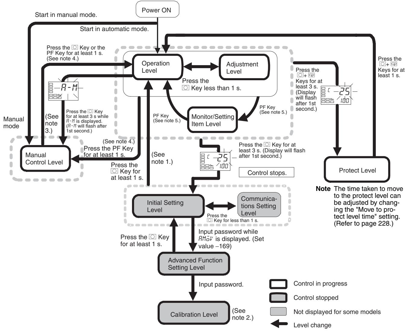
Note (1) You can return to the operation level by executing a software reset.
(2) It is not possible to move to other levels from the calibration level by operating the keys on the front panel. It can be done only by first turning OFF the power.
(3) From the manual control level, key operations can be used to move to the operation level only.
(4) When the PF Setting parameter is set to A-M for a Controller with a PF Key (E5AN/EN).
(5) When the PF Setting parameter is set to PFDP for a Controller with a PF Key (E5AN/EN)
Parameter Flow
This section describes the parameters set in each level. Pressing the Key at the last parameter in each level returns to the top parameter in that level.
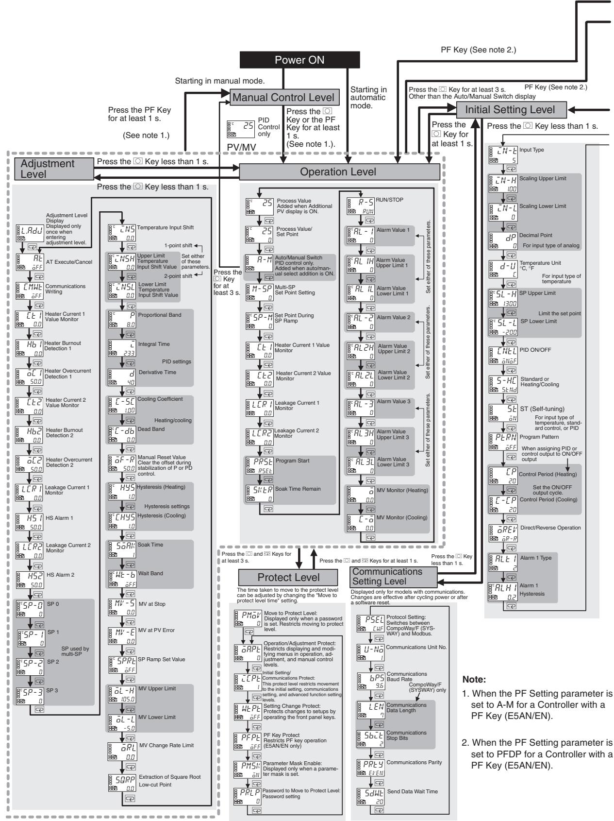
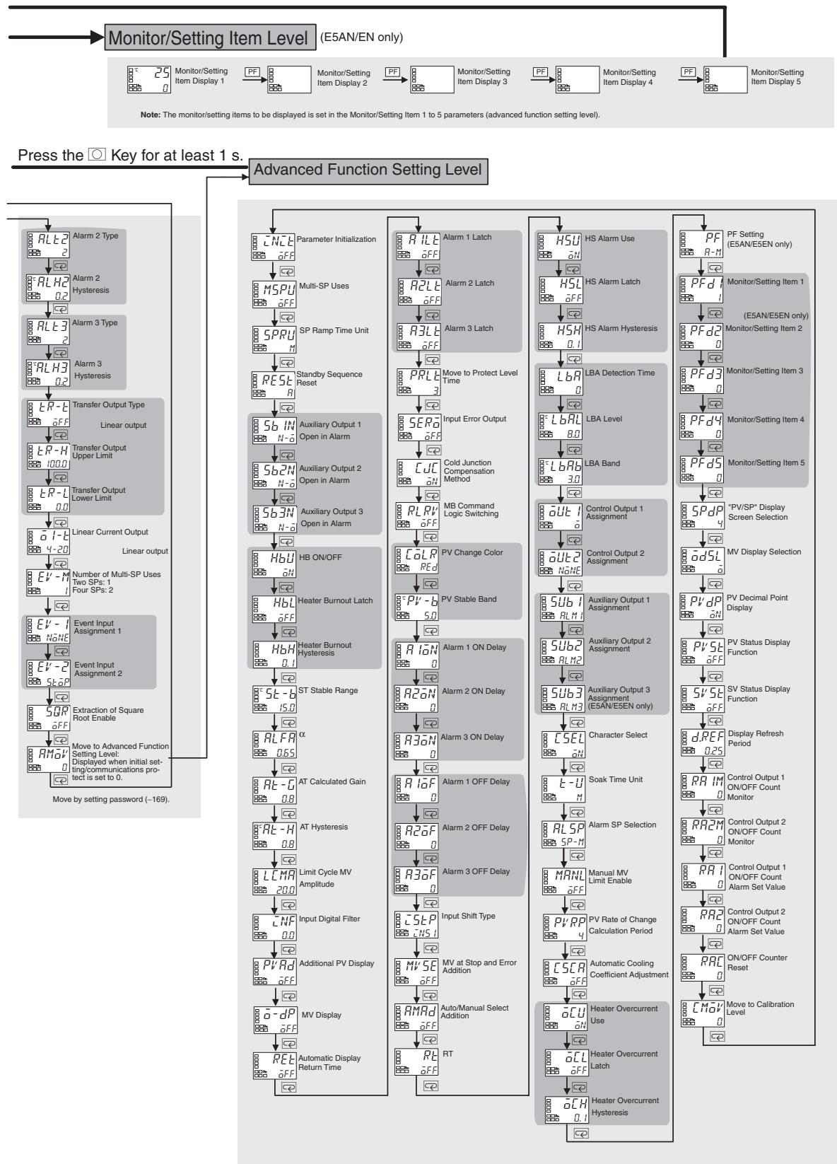
Index
Numerics
2-PID control, 54, 204
A
adjustment level, 16, 177
parameter operation list, 289
advanced function setting level, 17, 218
moving to, 108
parameter operation list, 294
alarm delays, 116
alarms, 13
alarm delays, 116
alarmhysteresis,93
alarm latch, 94
alarm outputs, 69
alarm types, 69
alarm values, 71
operation, 94
analog input, 94, 272
calibration, 265, 267
AT (auto-tuning), 62
autocontrol,103
auto/manual select addition, 124, 234
auto/manual switch, 166
auxiliary output 1 assignment, 240
auxiliary output 2 assignment, 241
auxiliary output 3 assignment, 242
auxiliary outputs 1, 2 and 3, 40
wiring, 41
B
basic model
E5AN, 9
E5CN, 6
E5CN-U,7
E5EN, 9
E5GN, 11
C
calibration
analog input, 265, 267
current input, 267
indication accuracy, 270
input types, 260
platinum resistance thermometer, 264
registering calibration data, 260
thermocouple, 260
user calibration, 260
voltage input, 268
characteristics, 277
cold junction compensator
connecting, 261
communications
operation commands, 112
wiring
RS-232C, 44
RS-485, 42
communications function, 14
communications setting level, 17, 255
parameter operation list, 299
control outputs, 13
control outputs 1 and 2
wiring, 37, 39
control periods, 54, 206
Controllers with Analog Input, 267
Controllers with Analog Inputs, 259, 268
Controllers with Thermocouple/Resistance Thermometer
Universal Input, 258, 265
cooling coefficient
setting, 98
current input
calibration, 267
current transformer
calculating detection current, 75
Current Transformers (CT), 74, 279
CT inputs
wiring, 42
external dimensions, 279
E54-CT1,279
E54-CT3,279
specifications, 278, 279
Current Value Exceeds (error display), 282
D
dead band, 97
setting, 98
derivative time, 68
detection current, 75
dimensions, 22
E5AN, 22
E5CN, 22
E5CN-U, 22
E5EN, 22
E5GN, 23
direct operation, 55, 206
Display Range Exceeded (error display), 281
down key, 5
E
error displays, 281
Current Value Exceeds, 282
Display Range Exceeded, 281
HeaterBurnout,283
Heater Overcurrent, 283
HS Alarm, 283
Input Error, 281
Memory Error, 282
event inputs, 13, 41, 99, 101
wiring, 41
external dimensions
Current Transformer (CT), 279
external power supply for ES1B, 14, 44, 90, 276
F
front panel
E5AN, 2
E5CN, 2
E5CN-U, 2
E5EN, 3
E5GN, 3
H
HB alarm (heater burnout alarm), 73
settings, 80
HeaterBurnout(errordisplay),283
heaterburnoutalarm,13,276
heaterburnouthysteresis,223
heaterburnoutlatch,223
heater overcurrent
hysteresis, 247
latch, 246
heating/cooling control, 95, 189, 193, 204
cooling coefficient, 97, 189
dead band, 97, 189
setting, 98
HS alarm, 13, 73, 276
settings, 82
HS Alarm (error display), 283
hysteresis, 60, 62
1
I/O configuration, 6
basic model
E5AN, 9
E5CN, 6
E5CN-U,7
E5EN, 9
E5GN, 11
main functions, 12
indication accuracy, 270
indicators
explanation, 4
operation, 4
infrared temperature sensor, 270
initial setting level, 17, 199
parameter operation list, 291
initial setting/communications protect, 110
initial settings, 50
examples, 50, 51
initialization, 220
Input Error (error display), 281
input sensor types, 12, 200
input shift, 89
one-point shift, 89
two-point shift, 90
calculating, 90
input types, 52, 303
default values, 200
list, 53
setting, 52
inputs
wiring, 36
installation, 22, 25
E5AN/E5EN
mounting the terminal cover, 26
mounting to the panel, 26
E5CN/E5CN-U
mounting the terminal cover, 26
mounting to the panel, 25
E5GN
mounting to the panel, 27
panelcutout
E5AN, 24
E5CN, 24
E5CN-U, 24
E5EN, 24
E5GN, 25
removing from case
E5AN, 29
E5CN, 28
E5EN, 29
removing the terminal block
E5GN, 30
integral time, 68, 188
K
keys
down key, 5
key operations, 15
levelkey,5
modekey,5
operations, 5
upkey,5
L
LBA (loop burnout alarm), 118
band, 119
detection time, 119, 120
level, 119, 120
levelkey,5
loopburnoutalarm(LBA),118
M
main functions, 12
manual control, 103, 122
manual control level, 16
moving to, 123
parameter operation list, 294
manual setup, 68
Memory Error (error display), 282
modekey,5
mounting, 25
terminal cover
E5AN/E5EN,26
E5CN/E5CN-U,26
to panel
E5AN/E5EN, 26
E5CN/E5CN-U,25
E5GN, 27
multi-SP, 101, 167
MV at PV error, 137, 233
MV at stop, 136, 233
N
No.1 display, 4
No. 2 display, 4
0
ON/OFF control, 54, 204
setting, 61
one-point shift, 91
operation level, 16, 163
parameter operation list, 288
operation/adjustmentprotect,110
output functions
assignments, 56
output limits, 136
output periods, 206
output specifications
setting, 54
P
panelcutout
E5AN, 24
E5CN/E5CN-U, 24
E5EN, 24
E5GN, 25
parameter flow, 305
parameter operation list, 288
adjustment level, 289
manual control level, 294
operation level, 288
parameter operation lists
advanced function setting level, 294
communications setting level, 299
initial setting level, 291
protect level, 299
parameter structure, 258
parameters
additional PV display, 226
adjustment level display, 179
alarm 1 hysteresis, 209
alarm 1 latch, 227
alarm 1 OFF delay, 232
alarm 1 ON delay, 232
alarm 1 type, 207
alarm 2 hysteresis, 209
alarm 2 latch, 227
alarm 2 OFF delay, 232
alarm 2 ON delay, 232
alarm 2 type, 209
alarm 3 hysteresis, 209
alarm 3 latch, 227
alarm 3 OFF delay, 232
alarm 3 ON delay, 232
alarm 3 type, 210
alarm SP selection, 244
alarm value 1, 172
alarm value 2, 173
alarm value 3, 173
alarm value lower limit 1, 174
alarm value lower limit 2, 174
alarm value lower limit 3, 175
alarm value upper limit 1, 174
alarm value upper limit 2, 174
alarm value upper limit 3, 175
alpha, 224
AT calculated gain, 225
AT execute/cancel, 179
AT hysteresis, 225
auto/manual select addition, 234
auto/manual switch, 166
automatic cooling coefficient adjustment, 245
automatic display return time, 227
auxiliary output 1 assignment, 240
auxiliary output 1 open in alarm, 222
auxiliary output 2 assignment, 241
auxiliary output 2 open in alarm, 222
auxiliary output 3 assignment, 242
auxiliary output 3 open in alarm, 222
character select, 243
cold junction compensation method, 229
communications baud rate, 255
communications data length, 255
communications parity, 255
communications stop bits, 255
communications Unit No., 255
communications writing, 180
control output 1 assignment, 238
control output 1 ON/OFF count alarm set value, 253
control output 1 ON/OFF count monitor, 252
control output 2 assignment, 239
control output 2 ON/OFF count alarm set value, 253
control output 2 ON/OFF count monitor, 252
control period (cooling), 206
control period (heating), 206
cooling coefficient, 189
dead band, 189
decimal point, 202
derivative time, 188
direct/reverse operation, 206
display refresh period, 251
event input assignment *, 216
extraction of square root enable, 216
extraction of square root low-cut point, 194
HB ON/OFF, 222
heaterburndetction1,181
heaterburndetction2,183
heaterburnouthysteresis,223
heaterburnoutlatch,223
heater current 1 value monitor, 168, 180
heater current 2 value monitor, 169, 182
heater overcurrent detection 1, 181
heater overcurrent detection 2, 183
heater overcurrent hysteresis, 247
heater overcurrent latch, 246
heater overcurrent use, 246
HS alarm 1, 184
HS alarm 2, 185
HS alarm hysteresis, 236
HS alarm latch, 235
HS alarm use, 235
hysteresis (cooling), 190
hysteresis (heating), 190
initial setting/communications protect, 160
input digital filter, 226
input error output, 228
input shift type, 233
input type, 200
integral time, 188
LBA band, 237
LBA detection time, 236
LBA level, 237
leakage current 1 monitor, 170, 184
leakage current 2 monitor, 170, 185
limit cycle MV amplitude, 225
linear current output, 212
lower-limit temperature input shift value, 187
manual MV limit enable, 244
manual reset value, 190
MB command logic switching, 229
monitor/setting item *, 248
monitor/setting item display 1 to 5, 196
move to advanced function setting level, 217
move to calibration level, 254
move to protect level, 160
move to protect level time, 228
multi-SP set point setting, 167
multi-SP uses, 220
MV (manual MV), 197
MV at PV error, 192
MV at stop, 192
MV at stop and error addition, 233
MV change rate limit, 194
MV display, 227
MV display selection, 249
MV lower limit, 193
MV monitor (cooling), 176
MV monitor (heating), 175
MV upper limit, 193
number of multi-SP uses, 213
ON/OFF counter reset, 254
operation/adjustmentprotect,160
parameter initialization, 220
parameter mask enable, 161
password to move to protect level, 162
PF key protect, 161
PF setting, 247
PID ON/OFF, 204
processvalue,165
process value/set point, 165
program pattern, 205
program start, 171
proportional band, 188
protocol setting, 255
PV change color, 230
PV decimal point display, 250
PV rate of change calculation period, 245
PV stable band, 231
PV status display function, 250
PV/MV (manual MV), 197
PV/SP display screen selection, 249
RT, 234
RUN/STOP, 172
scaling lower limit, 202
scaling upper limit, 202
selecting, 17
send data wait time, 255
set point during SP ramp, 167
setting change protect, 161
soak time, 191
soak time remain, 171
soak time unit, 243
SP0,186
SP1,186
SP2,186
SP3,186
SP lower limit, 203
SP ramp set value, 193
SP ramp time unit, 220
SP upper limit, 203
ST (self-tuning), 205
ST stable range, 224
standard or heating/cooling, 204
standby sequence reset, 221
SV status display function, 251
temperature input shift, 186
temperature unit, 202
transfer output lower limit, 212
transfer output type, 210
transfer output upper limit, 212
upper-limit temperature input shift value, 187
wait band, 191
part names, 2
password, 111, 112
PID constants, 62, 65
settingmanually,68
PID control
setting, 61
PID ON/OFF
Page, 193
platinum resistance thermometer, 271
calibration, 264
power supply
wiring, 35
precautions
wiring, 33
process value (PV), 165
program end, 132
output, 132
program patterns, 130
proportional action, 68
proportional band, 68
protect level, 16, 110, 159
moving to, 112, 160, 228
communications operation command, 112
password, 111, 162
parameter operation list, 299
protection, 110
initial setting/communications, 110, 160
operation/adjustment, 110, 160
setting change, 110, 111
PV display
color change, 113
stable band, 114
PV/MV, 197
R
ratings, 275
removing from case
E5AN/E5EN,29
E5CN, 28
removing the terminal block
E5GN, 30
reverse operation, 55, 206
RT (robust tuning), 66, 234
run/stop control, 103
s
scaling
upper and lower limits for analog inputs, 94
screwless clamp terminals, 34
self-tuning (ST), 64, 205
sensor input
control range, 303
indication range, 303
setting range, 303
sensor types, 200
set point (SP), 59
limiter, 104
limiting change rate, 106
lower limit, 106
ramp, 106
setting, 59, 61
setting upper and lower limits, 104
switching between SPs, 102
upper limit, 105
setting change protect, 110
setting level configuration, 15
setting levels
diagram, 305
settings
cooling coefficient, 98
dead band, 98
event input, 99
HB alarm (heater burnout alarm), 80
moving to advanced function setting level, 80
heating/cooling control, 98
HS alarm, 82
moving to advanced function setting level, 81, 82
hysteresis, 62
LBA detection time, 119
password, 112
PID ON/OFF, 61
saving, 18
SP lower limit, 106
SP upper limit, 105
switching between SPs, 102
shifting input values, 89
simple program function, 129, 135
controlling start, 103
starting, 131
soak time, 131
SP ramp, 106
alarm operations, 108
operation at startup, 107
restrictions, 107
specifications, 275
Current Transformer (CT), 278, 279
external power supply for ES1B, 45
output, 54
USB-Serial Conversion Cable, 280
ST (self-tuning), 64
ST stable range, 65
startup conditions, 65
standard control, 204
standby sequence, 93
startup
conditions, 65
operation, 107
support software port, 45
T
temperature input, 12, 13
shift values, 93
temperature unit, 4, 54
terminals
arrangement
E5AN/E5EN,32
E5CN, 31
E5CN-U,32,33
wiring, 31
thermocouple, 270
calibration, 260
Thermocouple/Resistance Thermometer
input type, 264, 265
universal input type, 265
three-position control, 60
transfer output, 126
type, 127
troubleshooting, 284
two-point shift, 90, 92, 93
calculating, 90
U
upkey,5
USB-Serial Conversion Cable
specifications, 280
user calibration, 260
V
voltage input
calibration, 268
W
wait band, 131
wiring, 35
auxiliary outputs 1, 2, and 3, 40
communications
RS-232C, 44
RS-485, 42
control output 1, 37
control output 2, 39
CT inputs, 42
event inputs, 41
external power supply for ES1B, 44
inputs, 36
power supply, 35
precautions, 33
terminal arrangement, 31
terminals, 31
Revision History
A manual revision code appears as a suffix to the catalog number on the front cover of the manual.
Cat. No. H156-E1-03
Revision code
The following table outlines the changes made to the manual during each revision. Page numbers refer to the previous version.
| Revision code | Date | Revised content |
| 01 | January 2008 | Original production |
| 01A | March 2008 | Page 9: Added case color information to the model number legend. |
| 02 | March 2009 | Pages xii and xiv: Added information on shipping standards and corrected mistakes. Pages 26, 96,236, 246, 255, 263, and 277: Made minor corrections. Pages 62 to 67: Made minor corrections to graphics. Page 80: Replaced graphic and changed step 2. |
| 03 | September 2009 | Added the E5GN. |
OMRON Corporation
Industrial Automation Company
Control Devices Division H.Q.
Industrial Component Division
2-2-1 Nishikusatsu, Kusatsu-shi,
Shiga, 525-0035 Japan
Tel: (81) 77-565-5160/Fax: (81) 77-565-5569
OMRON ELECTRONICS LLC
One Commerce Drive Schaumburg,
IL 60173-5302 U.S.A.
Tel: (1) 847-843-7900/Fax: (1) 847-843-7787
OMRON ASIA PACIFIC PTE. LTD.
No. 438A Alexandra Road # 05-05/08 (Lobby 2),
Alexandra Technopark, Singapore 119967
Tel: (65) 6835-3011/Fax: (65) 6835-2711
Regional Headquarters
OMRON EUROPE B.V.
Wegalaan 67-69-2132 JD Hoofddorp
The Netherlands
Tel: (31)2356-81-300/Fax: (31)2356-81-388
OMRON (CHINA) CO., LTD.
Room 2211, Bank of China Tower,
200 Yin Cheng Zhong Road.
PuDong New Area, Shanghai, 200120, China
Tel: (86) 21-5037-2222/Fax: (86) 21-5037-2200
Authorized Distributor:
© OMRON Corporation 2008 All Rights Reserved.
In the interest of product improvement,
specifications are subject to change without notice.
- E5CN
- E5AN
- E5EN
- E5GN
- Digital Temperature Controllers
- E5CN/E5AN/E5EN/E5GN Digital Temperature Controllers
- Preface
- Visual Aids
- OMRON, 2008
- Safety Precautions
- Definition of Precautionary Information
- Symbols
- Precautions for Safe Use
- Service Life
- - Ambient Noise
- - Ensuring Measurement Accuracy
- Waterproofing
- Precautions for Operation
- Shipping Standards
- ■ Application Conditions
- 1) Installation Location
- 2) Wiring Conditions
- Ferrite Core Connection Examples
- E5CN/E5CN-H
- E5AN/E5EN/E5AN-H/E5EN-H
- Preparations for Use
- Upgraded Functions
- Terminal Arrangements
- Body Drawout
- Dimensions
- ■ Terminal Block Configuration
- Wire Connections
- ■ Wiring Terminals
- ■ Removing the Terminal Block
- Communications Characteristics
- Other Upgrades
- Conventions Used in This Manual
- Model Notation
- Meanings of Abbreviations
- How to Read Display Symbols
- TABLE OF CONTENTS
- SECTION 1
- Introduction. 1
- SECTION 2
- Preparations 21
- SECTION 3
- Basic Operation. 49
- SECTION 4
- Applications Operations. 87
- SECTION 5
- Parameters. 157
- SECTION 6
- CALIBRATION 257
- Appendix 275
- Index. 309
- Revision History 317
- About this Manual:
- - Overview
- - Setup
- - Basic Operations
- Operations for Applications
- - User Calibration
- - Appendix
- WARNING
- SECTION 1 Introduction
- 1-1 Names of Parts
- 1-1-1 Front Panel
- 1-1-2 Explanation of Indicators
- 1-1-3 Using the Keys
- 1-2 I/O Configuration and Main Functions
- 1-2-1 I/O Configuration
- Note
- Model Number Structure
- Model Number Legend
- Controllers
- E5CN-□M□-500 1234567
- Control Output 1
- Auxiliary Outputs *2
- Input Type
- Power Supply Voltage
- Case Color
- Option Units
- E53-CN□□□ 1234
- Applicable Controller
- Function 1
- Function 2
- Version
- E5CN-□U 1234
- Output Type
- Number of Alarms
- Input Type
- Plug-in type
- Model Number Legends
- E5AN/EN-3M-500-N 123456789
- Auxiliary Outputs
- Heater Burnout/Heater Short, Control Output 2, or External Power Supply for ES1B
- Option
- Input Type
- Power Supply Voltage
- Case Color
- Terminal Cover
- Version
- Function
- E5GN-□□□□□-□-□-□ 12345678
- Option
- Terminal Type
- Communications Protocol
- 1-2-2 Main Functions
- Input Sensor Types
- Control Outputs
- Alarms
- Control Adjustment
- Event Inputs
- Heater Burnout, HS Alarm, and Heater Overcurrent
- 1-3 Setting Level Configuration and Key Operations
- Protect Level
- Operation Level
- Adjustment Level
- Monitor/Setting Item Level
- Manual Control Level
- Initial Setting Level
- Advanced Function Setting Level
- Communications Setting Level
- Calibration Level
- 1-3-1 Selecting Parameters
- 1-3-2 Saving Settings
- 1-4 Communications Function
- Setting Communications Data
- 1-5 Insulation Block Diagrams
- SECTION 2 Preparations
- 2-1 Installation
- 2-1-1 Dimensions
- 2-1-2 Panel Cutout
- E5CN/CN-U
- 2-1-3 Mounting
- Mounting to the Panel
- 1,2,3...
- Mounting the Terminal Cover
- E5AN/EN
- 2-1-4 Removing the Temperature Controller from the Case
- Removing the Terminal Block
- 2-2 Wiring Terminals
- 2-2-1 Terminal Arrangement
- 2-2-2 Precautions when Wiring
- 2-2-3 Wiring
- Power supply
- Input
- Control Output 1
- Control Output 2
- Auxiliary Outputs 1, 2, and 3
- CT Inputs
- Communications
- RS-485
- Communications Unit Connection Diagram
- RS-232C (E5AN/EN/GN Only)
- 2-3 Using the Support Software Port
- Procedure
- Basic Operation
- 3-1 Initial Setting Examples
- Explanation of Examples
- Example 1
- Example 2
- 3-2 Setting the Input Type
- 3-2-1 Input Type
- Operating Procedure
- 3-3 Selecting the Temperature Unit
- 3-3-1 Temperature Unit
- 3-4 Selecting PID Control or ON/OFF Control
- 2-PID Control
- ON/OFF Control
- 3-5 Setting Output Specifications
- 3-5-1 Control Periods
- 3-5-2 Direct and Reverse Operation
- 3-5-3 Assigned Output Functions
- Auxiliary Output Opening or Closing in Alarm
- 3-6 Setting the Set Point (SP)
- 3-6-1 Changing the SP
- 3-7 Using ON/OFF Control
- 3-7-1 ON/OFF Control
- Hysteresis
- Three-position Control
- 3-7-2 Settings
- Setting the PID ON/OFF Parameter
- Setting the SP
- Setting the Hysteresis
- 3-8 Determining PID Constants (AT, ST, Manual Setup)
- 3-8-1 AT (Auto-tuning)
- AT Operations
- AT Calculated Gain
- AT Hysteresis
- Limit Cycle MV Amplitude
- 40% AT
- 3-8-2 ST (Self-tuning)
- PID Constants
- Startup Conditions
- ST Stable Range
- 3-8-3 RT (Robust Tuning)
- RT Features
- 3-8-4 Manual Setup
- Note Proportional Action
- 3-9 Alarm Outputs
- 3-9-1 Alarm Types
- 3-9-2 Alarm Values
- PV Change Rate Alarm
- Precaution
- 3-10 Using Heater Burnout, Heater Short, and Heater Overcurrent Alarms
- 3-10-1 Heater Burnout, Heater Short, and Heater Overcurrent Alarm Operations
- 3-10-2 Installing Current Transformers (CT)
- Single-phase Heaters
- Three-phase Heaters (E5AN-□□HH□-N, E5EN-□□HH□-N, and E53-CN□□HHN2 (for E5CN) 3-phase Heater Detection Models)
- 3-10-3 Calculating Detection Current Values
- 3-10-4 Application Examples
- Three-phase Heaters
- Delta Connecting Lines
- Star Connecting Lines
- V Connecting Lines
- 3-10-5 Settings: HB Alarm
- ■ Moving to the Advanced Function Setting Level
- Setting Heater Burnout Detection
- 3-10-6 Settings: Heater Short Alarm
- HS Alarm Settings
- 3-10-7 Settings: Heater Overcurrent Alarm
- Setting Heater Overcurrent Detection
- 3-11 Setting the No. 3 Display
- 3-11-1 PV/SP Display Selection
- MV Display for Heating and Cooling Control
- Applications Operations
- 4-1 Shifting Input Values
- 4-1-1 Shifting Inputs
- One-point shift
- Two-point shift
- 4-1-2 How to Calculate Input Shift Values for a 2-point Shift
- Preparations
- Method for a 1-point Shift
- Method for a 2-point Shift
- 2.
- Example of a 2-point Temperature Input Shift
- 4-2 Alarm Hysteresis
- 4-2-1 Standby Sequence
- Restart
- 4-2-2 Alarm Latch
- Summary of Alarm Operation
- Parameters
- 4-3 Setting Scaling Upper and Lower Limits for Analog Inputs
- 4-3-1 Analog Input
- 4-4 Executing Heating/Cooling Control
- 4-4-1 Heating/Cooling Control
- Dead Band
- Cooling Coefficient
- Automatic Cooling Coefficient Adjustment
- 4-4-2 Settings
- Setting Heating/Cooling Control
- Setting the Cooling Coefficient
- Setting the Dead Band
- 4-5 Using Event Inputs
- 4-5-1 Event Input Settings
- 4-5-2 How to Use the Multi-SP Function
- Using Event Inputs
- Two Event Inputs: Event Inputs 1 and 2
- Using Key Operations
- 4-5-3 Settings
- Switching between Set Points 0, 1, 2, and 3
- 4-5-4 Operation Commands Other than Multi-SP
- Executing Run/Stop Control
- Switching between Auto and Manual Control
- Controlling the Start of the Simple Program Function
- Control by Inverting Direct/Reverse Operation
- Switching 100\% AT Execute/Cancel
- Switching 40\% AT Execute/Cancel
- Switching Setting Change Enable/ Disable
- Switching Alarm Latch Cancel
- 4-6 Setting the SP Upper and Lower Limit Values
- 4-6-1 Set Point Limiter
- 4-6-2 Setting
- Setting the Set Point Upper-limit Value
- Set Point Upper Limit = 1000
- Setting the Set Point Lower-limit Value
- Set Point Lower Limit = -100
- 4-7 Using the SP Ramp Function to Limit the SP Change Rate 4-7-1 SP Ramp
- Operation at Startup
- Restrictions during SP Ramp Operation
- Alarms during SP Ramp Operation
- 4-8 Moving to the Advanced Function Setting Level
- 4-9 Using the Key Protect Level
- 4-9-1 Protection
- Operation/Adjustment Protect
- Initial Setting/ Communications Protect
- Setting Change Protect
- PF Key Protect
- 4-9-2 Entering the Password to Move to the Protect Level
- Example with a Password of 1234
- Example with No Password Set
- Setting the Password
- Example To set the Password to 1234
- Communications Operation Command to Move to the Protect Level
- 4-10 PV Change Color
- 4-10-1 PV Color Change Function
- PV Stable Band
- 4-10-2 Setting
- Setting the PV Change Color to Indicate Stable Status
- 4-11 Alarm Delays
- 4-11-1 Alarm Delays
- Operation of Alarm ON and OFF Delays (for an Upper-limit Alarm)
- Parameters Related to Alarm Delays
- 4-12 Loop Burnout Alarm
- 4-12-1 Loop Burnout Alarm (LBA)
- Determining the LBA Detection Time
- LBA Level
- LBA Band
- 4-13 Performing Manual Control
- 4-13-1 Manual Operation
- Manual MV Limit Enable
- Moving from the Operation Level to the Manual Control Level
- Using the PF Key to Move to the Manual Control Level
- Auto/Manual Select Addition
- 4-14 Using the Transfer Output
- 4-14-1 Transfer Output Function
- ■ Precision and User Calibration
- Transfer Output Type
- Transfer Scaling
- 4-15 Using the Simple Program Function
- 4-15-1 Simple Program Function
- Program Pattern
- ■ Pattern 1 (STOP)
- Pattern 2(CONT)
- Starting Method
- Soak Time and Wait Band
- 4-15-2 Operation at the Program End
- Display at the Program End
- Program End Output
- E5CN/CN-U, E5AN/EN
- Clearing the Program End Status
- 4-15-3 Application Example Using a Simple Program
- 4-16 Output Adjustment Functions
- 4-16-1 Output Limits
- 4-16-2 MV at Stop
- 4-16-3 MV at PV Error
- 4-17 Using the Extraction of Square Root Parameter
- Extraction of Square Roots
- 4-18 Setting the Width of MV Variation
- MV Change Rate Limit
- 4-19 Setting the PF Key
- 4-19-1 PF Setting (Function Key)
- Monitor/Setting Item
- Setting Monitor/Setting Items
- 4-20 Counting Control Output ON/OFF Operations
- 4-20-1 Control Output ON/OFF Count Function
- Control Output ON/OFF Counter Monitor Function
- Display When ON/OFF Count Alarm Occurs
- Control Output ON/OFF Count Alarm Function
- ON/OFF Counter Reset Function
- 4-21 Displaying PV/SV Status
- 4-21-1 PV and SV Status Display Functions
- PV Status Display Function
- SV Status Display Function
- 4-22 Logic Operations
- 4-22-1 The Logic Operation Function (CX-Thermo)
- 4-22-2 Using Logic Operations
- Starting Logic Operations
- Making the Settings
- 1,2,3... 1. Displaying the Library Import Dialog Box
- Example: Selecting Library 1
- Switching Work Bit Operations
- Selecting the Operation Type
- Selecting Input Assignments
- SECTION 5 Parameters
- 5-1 Conventions Used in this Section
- 5-1-1 Meanings of Icons Used in this Section
- 5-1-2 About Related Parameter Displays
- 5-1-3 The Order of Parameters in This Section
- 5-1-4 Alarms
- 5-2 Protect Level
- Initial Setting/Communications Protect
- PRLF
- Password to Move to Protect Level
- Related Parameters
- 5-3 Operation Level
- Process Value/Set Point (Display 1)
- Process Value/Set Point (Display 2)
- No. 3 Display (E5AN/EN)
- See
- R-M
- Auto/Manual Switch
- 5-4 Adjustment Level
- 5-5 Monitor/Setting Item Level
- Monitor/Setting Item Display 1 to 5
- 5-6 Manual Control Level
- PV/MV (Manual MV)
- 5-7 Initial Setting Level
- Input Type
- Temperature Unit
- SP Upper Limit
- SP Lower Limit
- Alarm 1 Type
- Alarm 2 Type
- Related Parameter
- Transfer Output Upper Limit
- Transfer Output Lower Limit
- Linear Current Output
- Number of Multi-SP Uses
- Extraction of Square Root Enable
- 5-8 Advanced Function Setting Level
- RESE
- Standby Sequence Reset
- INF
- Input Digital Filter
- PvRd
- Additional PV Display
- C oL R
- PV Change Color
- Control Output 1 Assignment
- aUT2
- Control Output 2 Assignment
- Auxiliary Output 1 Assignment
- SUB2
- Auxiliary Output 2 Assignment
- 5u63
- Auxiliary Output 3 Assignment
- Monitor/Setting Item * (*: 1 to 5)
- 515
- d.REF
- Display Refresh Period
- 5-9 Communications Setting Level
- CALIBRATION
- 6-1 Parameter Structure
- Controllers with an Analog Input
- 6-2 User Calibration
- 6-2-1 Calibrating Inputs
- 6-2-2 Registering Calibration Data
- 6-3 Thermocouple Calibration (Thermocouple/Resistance Thermometer Input)
- 6-3-1 Preparations
- - Connecting the Cold Junction Compensator
- 6-4 Platinum Resistance Thermometer Calibration (Thermocouple/Resistance Thermometer Input)
- 1,2,3... 1. Connect the power supply.
- Turn the power ON.
- Move to the calibration level.
- Execute calibration for the main input.
- 6-5 Analog Input Calibration (Thermocouple/Resistance Thermometer Input)
- 6-6 Calibrating Analog Input (Analog Input)
- 6-6-1 Calibrating a Current Input
- 6-6-2 Calibrating a Voltage Input
- 6-7 Checking Indication Accuracy
- 6-7-1 Thermocouple or Infrared Temperature Sensor
- 6-7-2 Platinum Resistance Thermometer
- 6-7-3 Analog Input
- Appendix
- Specifications
- Rating and Characteristics of Options
- Waterproof Packing
- Current Transformer (CT)
- External Dimensions
- E58-CIFQ1 USB-Serial Conversion Cable
- Compatible Operating Environment
- Appearance and Nomenclature
- Appearance
- Error Displays
- Input Error
- Meaning
- Action
- Operation at Error
- Display Range Exceeded
- AD Converter Error
- Operation
- Memory Error
- Current Value Exceeds
- Heater Burnout
- HS Alarm
- Heater Overcurrent
- Troubleshooting
- Checking Problems
- Symptom: Cannot Communicate or a Communications Error Occurs
- Parameter Operation Lists
- Initialization According to Parameter Changes
- Control Range
- Setting Levels Diagram
- Parameter Flow
- Index
- Numerics
- A
- B
- C
- D
- E
- F
- H
- 1
- K
- L
- M
- N
- 0
- P
- R
- s
- T
- U
- V
- W
- Revision History
- OMRON Corporation
- Regional Headquarters
- OMRON (CHINA) CO., LTD.
- Authorized Distributor:
Marque : OMRON
Modèle : E5EN
Catégorie : Contrôleur de température