
E5CN-U - Contrôleur de température OMRON - Notice d'utilisation et mode d'emploi gratuit
Retrouvez gratuitement la notice de l'appareil E5CN-U OMRON au format PDF.

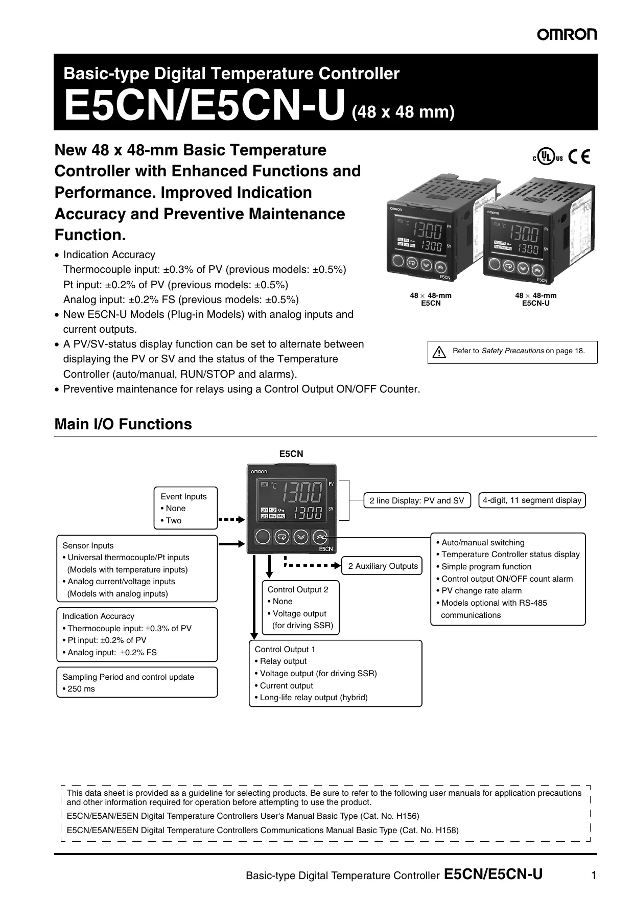

| Type de produit | Contrôleur de température numérique |
| Modèle | E5CN-U (type enfichable) |
| Dimensions (face avant) | 48 x 48 mm |
| Profondeur | 78 mm |
| Poids | Environ 110 g (contrôleur seul) |
| Alimentation | 100 à 240 VAC, 50/60 Hz ou 24 VAC/VDC |
| Consommation | 6 VA max. (100-240 VAC), 3 VA/2 W max. (24 V) |
| Méthode de contrôle | ON/OFF ou PID 2 degrés avec auto-réglage |
| Types d'entrée | Thermocouple, sonde à résistance de platine, courant/tension analogique |
| Sorties de contrôle | Relais (SPDT), tension pour SSR (12 VDC/21 mA) ou courant (4-20 mA) |
| Sorties auxiliaires | 2 sorties relais (250 VAC, 3 A) |
| Fonctions principales | Affichage PV/SV, alarmes multiples, détection de rupture de chauffage, communication RS-485 (option), autotuning, extraction de racine carrée, compteur ON/OFF |
| Indice de protection | Face avant : IP50, Boîtier arrière : IP20, Bornes : IP00 |
| Protection mémoire | Mémoire non volatile (1 000 000 écritures) |
| Température de fonctionnement | -10 à 55 °C (sans condensation) |
| Humidité de fonctionnement | 25 à 85 % HR |
| Montage | Encastrement dans panneau (découpe 45 x 45 mm) |
| Accessoires fournis | Adaptateur de montage, joint d'étanchéité (non fourni pour E5CN-U) |
| Entretien et nettoyage | Nettoyer avec un chiffon doux imbibé d'alcool ; ne pas utiliser de diluant |
| Sécurité | Ne pas toucher les bornes sous tension ; utiliser des fusibles ; respecter les couples de serrage (0,5 N·m pour E5CN-U) |
| Pièces détachées et réparabilité | Embases (P2CF-11, P3GA-11), couvercle de bornes (E53-COV17), transformateur de courant (E54-CT1/CT3), câble de conversion USB-série (E58-CIFQ1) |
| Informations générales | Normes : UL 61010-1, CSA C22.2 No. 1010-1, EN 61010-1 ; EMC : EN 61326 |
FOIRE AUX QUESTIONS - E5CN-U OMRON
Questions des utilisateurs sur E5CN-U OMRON
0 question sur cet appareil. Repondez a celles que vous connaissez ou posez la votre.
Poser une nouvelle question sur cet appareil
Téléchargez la notice de votre Contrôleur de température au format PDF gratuitement ! Retrouvez votre notice E5CN-U - OMRON et reprennez votre appareil électronique en main. Sur cette page sont publiés tous les documents nécessaires à l'utilisation de votre appareil E5CN-U de la marque OMRON.
MODE D'EMPLOI E5CN-U OMRON
Basic-type Digital Temperature Controller
E5CN/E5CN-U (48 x 48 mm)
New 48 x 48-mm Basic Temperature Controller with Enhanced Functions and Performance. Improved Indication Accuracy and Preventive Maintenance Function.
- Indication Accuracy
Thermocouple input: ± 0.3% of PV (previous models: ± 0.5% )
Pt input: ± 0.2% of PV (previous models: ± 0.5% )
Analog input: ± 0.2% FS (previous models: ± 0.5% )
- New E5CN-U Models (Plug-in Models) with analog inputs and current outputs.
- A PV/SV-status display function can be set to alternate between displaying the PV or SV and the status of the Temperature Controller (auto/manual, RUN/STOP and alarms).
- Preventive maintenance for relays using a Control Output ON/OFF Counter.

Refer to Safety Precautions on page 18.
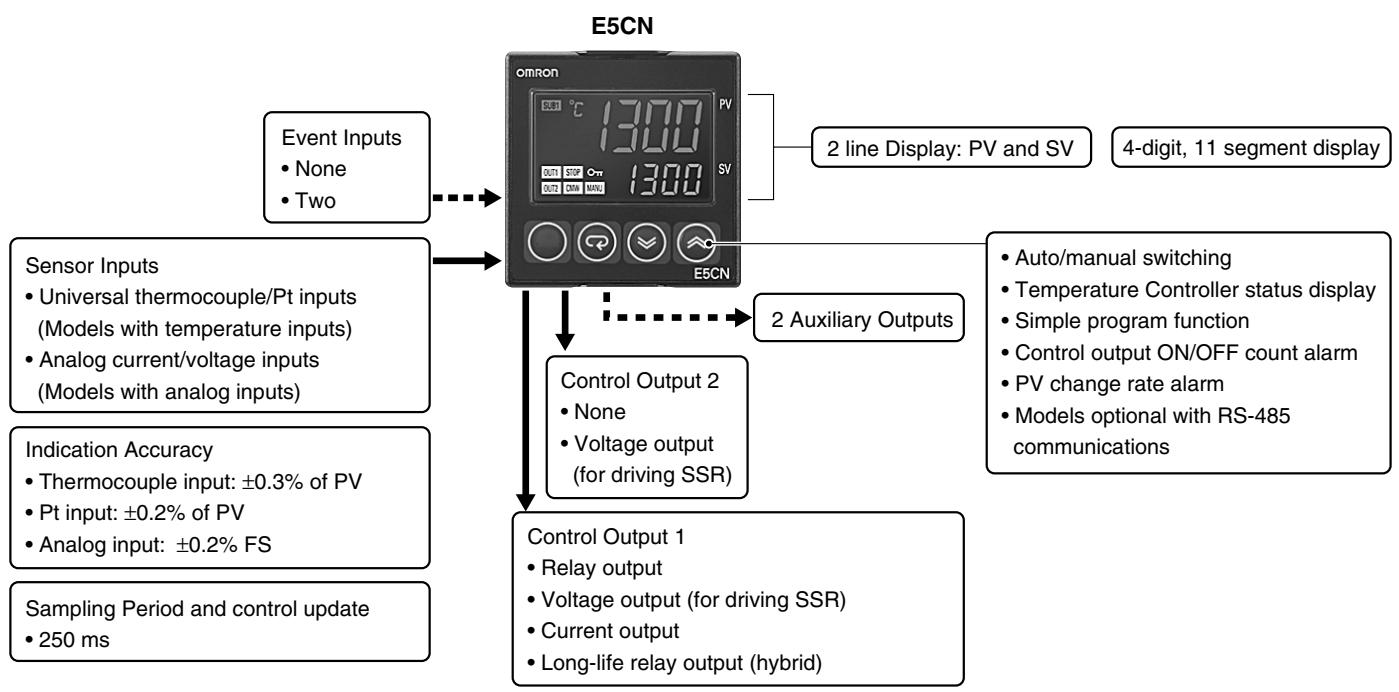
Main I/O Functions
This data sheet is provided as a guideline for selecting products. Be sure to refer to the following user manuals for application precautions and other information required for operation before attempting to use the product.
E5CN/E5AN/E5EN Digital Temperature Controllers User's Manual Basic Type (Cat. No. H156)
E5CN/E5AN/E5EN Digital Temperature Controllers Communications Manual Basic Type (Cat. No. H158)
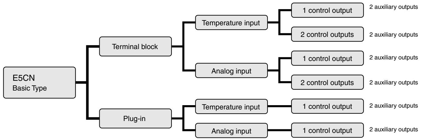
Note: All models can be used for Heating, Cooling and Heating & Cooling control
Model Number Structure
Model Number Legend Controllers

- Control Output 1
R:Relay output
Q: Voltage output (for driving SSR)
C: Current output
Y: Long-life relay output (hybrid) *1
- Auxiliary Outputs *2
2: Two outputs
- Option
M: Option Unit can be mounted.
- Input Type
T: Universal thermocouple/platinum resistance thermometer
L: Analog current/voltage input
- Power Supply Voltage
Blank: 100 to 240 VAC
D:24VAC/VDC
- Case Color
Blank: Black
W: Silver (contact your local sales for more information)
- Terminal Cover
-500: With terminal cover
Option Units
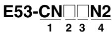
- Applicable Controller CN: E5CN
- Function 1
Blank: None
Q: Control output 2 (voltage for driving SSR)
P: Power supply for sensor
- Function 2
Blank: None
H: Heater burnout/SSR failure/Heater overcurrent detection (CT1)
HH: Heater burnout/SSR failure/Heater overcurrent detection (For 3-phase heater applications, 2x CT)
B: Two event inputs
03: RS-485 communications
H03: Heater burnout/SSR failure/Heater overcurrent detection (CT1) + RS-485 communications
HB: Heater burnout/SSR failure/Heater overcurrent detection (CT1) + Two event inputs
HH03: Heater burnout/SSR failure/Heater overcurrent detection (For 3-phase heater applications, 2x CT)
- Version
N2: Applicable only to models produced after January 2008 (Box marked with N6)
Note: Not all combinations of function 1 and function 2 specifications are possible for Option Units (E53-CN□□N2).
1. Always connect an AC load to a long-life relay output. The output will not turn OFF if a DC load is connected because a triac is used for switching the circuit. For details, check the conditions in Ratings.
2. Auxiliary outputs are contact outputs that can be used to output alarms, control or results of logic operations.
Ordering Information
Controllers with Terminal Blocks
| Size | Case color | Power supply voltage | Input type | Auxiliary outputs | Control output 1 | Model |
| 1/16 DIN 48×48×78 (W×H×D) | Black | 100 to 240 VAC | Thermocouple or Resistance thermometer | 2 | Relay output | E5CN-R2MT-500 |
| Voltage output (for driving SSR) | E5CN-Q2MT-500 | |||||
| Current output | E5CN-C2MT-500 | |||||
| Long-life relay output (hybrid) | E5CN-Y2MT-500 | |||||
| 24 VAC/VDC | Thermocouple or Resistance thermometer | 2 | Relay output | E5CN-R2MTD-500 | ||
| Voltage output (for driving SSR) | E5CN-Q2MTD-500 | |||||
| Current output | E5CN-C2MTD-500 | |||||
| 100 to 240 VAC | Analog (current/voltage) | 2 | Relay output | E5CN-R2ML-500 | ||
| Voltage output (for driving SSR) | E5CN-Q2ML-500 | |||||
| Current output | E5CN-C2ML-500 | |||||
| Long-life relay output (hybrid) | E5CN-Y2ML-500 | |||||
| 24 VAC/VDC | Analog (current/voltage) | 2 | Relay output | E5CN-R2MLD-500 | ||
| Voltage output (for driving SSR) | E5CN-Q2MLD-500 | |||||
| Current output | E5CN-C2MLD-500 |
Note: add power supply voltage to model to complete ordering code (ie. E5CN-R2MT-500 AC100-240 or E5CN-R2MTD-500 AC/DC24)
Option Units
One of the following Option Units can be mounted to provide the E5CN with additional functions.
| Functions | Model | ||||
| Event inputs | E53-CNBN2 | ||||
| Event inputs | Control output 2(Voltage for driving SSR) | E53-CNQBN2 | |||
| Event inputs | Heater burnout/SSR failure/Heater overcurrent detection | E53-CNHBN2 | |||
| Event inputs | External power supply for ES1B | E53-CNPBN2 | |||
| Communications RS-485 | E53-CN03N2 | ||||
| Communications RS-485 | Control output 2(Voltage for driving SSR) | E53-CNQ03N2 | |||
| Communications RS-485 | Heater burnout/SSR failure/Heater overcurrent detection | E53-CNH03N2 | |||
| Communications RS-485 | 3-phase heater burnout/SSR failure/Heater overcurrent detection | E53-CNHH03N2 | |||
| Communications RS-485 | External power supply for ES1B | E53-CNPO3N2 | |||
| Heater burnout/SSR failure/Heater overcurrent detection | Control output 2(Voltage for driving SSR) | E53-CNQHN2 | |||
| 3-phase heater burnout/SSR failure/Heater overcurrent detection | Control output 2(Voltage for driving SSR) | E53-CNQHHN2 | |||
| Heater burnout/SSR failure/Heater overcurrent detection | External power supply for ES1B | E53-CNPHN2 | |||
Note: Option Units cannot be used for plug-in models.
These Option Units are applicable only to models produced after January 2008 (Box marked with N6).
Model Number Legend (Plug-in-type Controllers)
E5CN-2U 1234
1. Output Type
R:Relay output
Q: Voltage output (for driving SSR)
C: Current output
2. Number of Alarms
2: Two alarms
3. Input Type
T: Universal thermocouple/platinum resistance thermometer
L: Analog Input
4. Plug-in type
U: Plug-in type
Ordering Information
Plug-in-type Controllers
| Size | Case color | Power supply voltage | Input type | Auxiliary outputs | Control output 1 | Model |
| 1/16 DIN | Black | 100 to 240 VAC | Thermocouple or resistance thermometer | 2 | Relay output | E5CN-R2TU |
| Voltage output (for driving SSR) | E5CN-Q2TU | |||||
| Current output | E5CN-C2TU | |||||
| Analog (current/voltage) | 2 | Relay output | E5CN-R2LU | |||
| Voltage output (for driving SSR) | E5CN-Q2LU | |||||
| Current output | E5CN-C2LU | |||||
| 24 VAC/VDC | Thermocouple or resistance thermometer | 2 | Relay output | E5CN-R2TDU | ||
| Voltage output (for driving SSR) | E5CN-Q2TDU | |||||
| Current output | E5CN-C2TDU |
Note: add power supply voltage to model to complete ordering code. (ie. E5CN-R2TU AC100-240 or E5CN-R2TDU AC/DC24)
Accessories (Order Separately)
USB-Serial Conversion Cable
| Model |
| E58-CIFQ1 |
Terminal Cover
| Connectable models | Terminal block models |
| Model | E53-COV17 |
Note: The Terminal Cover comes with the E5CN-□□□-500 models.
Waterproof Packing
| Model |
| Y92S-29 |
Note: The Waterproof Packing is included with the Controller only for models with terminal blocks.
Current Transformers (CTs)
| Hole diameter | Model |
| 5.8 dia. | E54-CT1 |
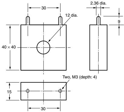
| 12.0 dia. | E54-CT3 |
Adapter
| Connectable models | Model |
| Terminal block models | Y92F-45 |
Note: Use this Adapter when the panel has been previously prepared for the E5B (72x72 mm panel cut-out).
Sockets (for Plug-in Models)
| Type | Model |
| Front-connecting Socket | P2CF-11 |
| Front-connecting Socket with Finger Protection | P2CF-11-E |
| Back-connecting Socket | P3GA-11 |
| Terminal Cover for Back-connecting socket with Finger Protection | Y92A-48G |
CX-Thermo Support Software
| Model |
| EST2-2C-MV4 |
Ratings
| Power supply voltage | No D in model number: 100 to 240 VAC, 50/60 HzD in model number: 24 VAC, 50/60 Hz; 24 VDC | ||
| Operating voltage range | 85% to 110% of rated supply voltage | ||
| Power consump-tion | E5CN | 100 to 240 VAC: 7.5 VA (max.) (E5CN-R2T at 100 VAC: 3.0 VA)24 VAC/VDC: 5 VA/3 W (max.) (E5CN-R2TD at 24 VAC: 2.7 VA) | |
| E5CN-U | 100 to 240 VAC: 6 VA (max.)24 VAC/VDC: 3 VA/2 W (max.) (models with current output: 4 VA/2 W) | ||
| Sensor input | Models with temperature inputsThermocouple: K, J, T, E, L, U, N, R, S, B, W, or PL IIPlatinum resistance thermometer: Pt100 or JPt100Infrared temperature sensor: 10 to 70°C, 60 to 120°C, 115 to 165°C, or 140 to 260°CVoltage input: 0 to 50 mV | ||
| Models with analog inputsCurrent input: 4 to 20 mA or 0 to 20 mAVoltage input: 1 to 5 V, 0 to 5 V, or 0 to 10 V | |||
| Input impedance | Current input: 150 Ω max., Voltage input: 1 MΩ min. (Use a 1:1 connection when connecting the ES2-HB.) | ||
| Control method | ON/OFF control or 2-PID control (with auto-tuning) | ||
| Control outputs | Relay output | E5CN | SPST-NO, 250 VAC, 3 A (resistive load), electrical life: 100,000 operations, minimum applicable load: 5 V, 10 mA |
| E5CN-U | SPDT, 250 VAC, 3 A (resistive load), electrical life: 100,000 operations, minimum applicable load: 5 V, 10 mA | ||
| Voltage output(for driving SSR) | E5CN | Output voltage: 12 VDC ±15% (PNP), max. load current: 21 mA, with short-circuit protection circuit | |
| E5CN-U | |||
| Current output | E5CN | 4 to 20 mA DC/0 to 20 mA DC, load: 600 Ω max., resolution: approx. 10,000 | |
| Long-life relay output | E5CN | SPST-NO, 250 VAC, 3 A (resistive load), electrical life: 1,000,000 operations, load power supply voltage: 75 to 250 VAC (DC loads cannot be connected.), minimum applicable load: 5 V, 10 mA, leakage current: 5 mA max. (250 VAC, 60 Hz) | |
| Auxiliary outputs | Number of outputs | 2 | |
| Output specifications | Relay output: SPST-NO, 250 VAC, 3 A (resistive load), electrical life: 100,000 operations, minimum applicable load: 5 V, 10 mA | ||
| Event inputs | Number of inputs | 2 | |
| External contactinput specifications | Contact input: ON: 1 kΩ max., OFF: 100 kΩ min. | ||
| Non-contact input: ON: Residual voltage: 1.5 V max., OFF: Leakage current: 0.1 mA max. | |||
| Current flow: Approx. 7 mA per contact | |||
| External power supply for ES1B | 12 VDC ±10%, 20 mA, short-circuit protection circuit provided | ||
| Setting method | Digital setting using front panel keys | ||
| Indication method | 11-segment digital display and individual indicators (7-segment display emulation also possible)Character height: PV: 11 mm, SV: 6.5 mm | ||
| Multi SP | Up to four set points (SP0 to SP3) can be saved and selected using event inputs, key operations, or serial communications. | ||
| Bank switching | Not supported | ||
| Other functions | Manual output, heating/cooling control, loop burnout alarm, SP ramp, other alarm functions, heater burnout detection, 40% AT, 100% AT, MV limiter, input digital filter, self-tuning, temperature input shift, run/stop, protection functions, control output ON/OFF counter, extraction of square root, MV change rate limit, logic operations, PV/SV status display, simple program, automatic cooling coefficient adjustment | ||
| Ambient operating temperature | -10 to 55°C (with no condensation or icing), for 3-year warranty: -10 to 50°C | ||
| Ambient operating humidity | 25% to 85% | ||
| Storage temperature | -25 to 65°C (with no condensation or icing) | ||
Input Ranges
Thermocouple/Platinum Resistance Thermometer (Universal Inputs)
| Input Type | Platinum resistance thermometer | Thermocouple | Infrared temperature sensor | Analog input | |||||||||||||||||||||||||
| Name | Pt100 | JPt100 | K | J | T | E | L | U | N | R | S | B | W | PLII | 10 to 70°C | 60 to 120°C | 115 to 165°C | 140 to 260°C | 0 to 50 mV | ||||||||||
| Temperature range (°C) | 2300 | Usable in the following ranges by scaling:-1999 to 9999 or -199.9 to 999.9 | |||||||||||||||||||||||||||
| 1800 | |||||||||||||||||||||||||||||
| 1700 | 1700 | ||||||||||||||||||||||||||||
| 1300 | 1300 | ||||||||||||||||||||||||||||
| 1300 | |||||||||||||||||||||||||||||
| 850 | |||||||||||||||||||||||||||||
| 850 | 850 | 850 | |||||||||||||||||||||||||||
| 600 | |||||||||||||||||||||||||||||
| 500.0 | 500.0 | 500.0 | |||||||||||||||||||||||||||
| 400.0 | 400 | 400.0 | 400 | 400.0 | |||||||||||||||||||||||||
| 100 | |||||||||||||||||||||||||||||
| 0.0 | 0.0 | 0.0 | -20.0 | -100 | -20.0 | -100 | -100 | -100 | -100 | -100 | -100 | -100 | -100 | -100 | -100 | -100 | -100 | -100 | -100 | 0 | 0 | 0 | 0 | 0 | 0 | 0 | 0 | ||
| -200 | -199.9 | -199.9 | -200 | -200 | -199.9 | -200 | -200 | -200 | -200 | -200 | -200 | -199.9 | -200 | -200 | -199.9 | -200 | -200 | -200 | -200 | -200 | -200 | -200 | -200 | -200 | -200 | -200 | -200 | -200 | |
| Setting number | 0 | 1 | 2 | 3 | 4 | 5 | 6 | 7 | 8 | 9 | 10 | 11 | 12 | 13 | 14 | 15 | 16 | 17 | 18 | 24 | 25 | 19 | 20 | 21 | 22 | 23 | |||
Shaded settings are the default settings.
The applicable standards for the input types are as follows:
K, J, T, E, N, R, S, B: JIS C 1602-1995, IEC 584-1
L:Fe-CuNi,DIN 43710-1985
U: Cu-CuNi, DIN 43710-1985
W: W5Re/W26Re, ASTM E988-1990
Models with Analog Inputs
| Input Type | Current | Voltage | |||
| Input specification | 4 to 20mA | 0 to 20 mA | 1 to 5 V | 0 to 5 V | 0 to 10 V |
| Setting range | usable in the following ranges by scaling: -1999 to 9999, -199.9 to 999.9, -19.99 to 99.99 or -1.999 to 9.999 | ||||
| Setting number | 0 | 1 | 2 | 3 | 4 |
Shaded settings are the default settings.
JPt100: JIS C 1604-1989, JIS C 1606-1989
Pt100: JIS C 1604-1997, IEC 751
PL II: According to Platinel II electromotive force charts from BASF (previously
Engelhard)
Alarm Outputs
Each alarm can be independently set to one of the following 13 alarm types. The default is 2: Upper limit.
Auxiliary outputs are allocated for alarms. ON delays and OFF delays (0 to 999 s) can also be specified.
Note: For models with heater burnout, SSR failure, and heater overcurrent detection, alarm 1 will be an OR output of the alarm selected from the following alarm types and the alarms for heater burnout, SSR failure, and heater overcurrent. To output only a heater burnout alarm, SSR failure alarm, and heater overcurrent alarm for alarm 1, set the alarm type to 0 (i.e., no alarm function).
| Set value | Alarm type | Alarm output operation | |
| When X is positive | When X is negative | ||
| 0 | Alarm function OFF | Output OFF | |
| 1*1 | Upper- and lower-limit | ONOFFLHSP | *2 |
| 2 | Upper limit | ONOFFXSP | ONOFFSP |
| 3 | Lower limit | ONOFFXSP | ONOFFSP |
| 4*1 | Upper- and lower-limit range | ONOFFLHSP | *3 |
| 5*1 | Upper- and lower-limit with standby sequence | ONOFFSP | *4 |
| 6 | Upper-limit with standby sequence | ONOFFXSP | ONOFFSP |
| 7 | Lower-limit with standby sequence | ONOFFXSP | ONOFFSP |
| 8 | Absolute-value upper-limit | ONOFF0 | ONOFF0 |
| 9 | Absolute-value lower-limit | ONOFF0 | ONOFF0 |
| 10 | Absolute-value upper-limit with standby sequence | ONOFF0 | ONOFF0 |
| 11 | Absolute-value lower-limit with standby sequence | ONOFF0 | ONOFF0 |
| 12 | LBA (for alarm 1 only) | --- | |
| 13 | PV change rate alarm | --- | |
1. With set values 1, 4 and 5, the upper and lower limit values can be set independently for each alarm type, and are expressed as "L" and "H."
2. Set value: 1, Upper- and lower-limit alarm
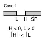
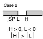
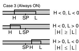
*3. Set value: 4, Upper- and lower-limit range
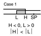
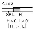
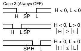
*4. Set value: 5, Upper- and lower-limit with standby sequence For Upper- and Lower-Limit Alarm Described Above
Case 1 and 2
Always OFF when the upper-limit and lower-limit hysteresis overlaps.
Case 3: Always OFF
*5. Set value: 5, Upper- and lower-limit with standby sequence Always OFF when the upper-limit and lower-limit hysteresis overlaps.
Characteristics
| Indication accuracy | Thermocouple: *1 Terminal block models (E5CN): (±0.3% of indicated value or ±1°C, whichever is greater) ±1 digit max. Plug-in models (E5CN-U): (±1% of indicated value or ±2°C, whichever is greater) ±1 digit max. Platinum resistance thermometer input: Terminal block models (E5CN) and plug-in models (E5CN-U): (±0.2% of indicated value or ±0.8°C, whichever is greater) ±1 digit max. Analog input: Terminal block models (E5CN) and plug-in models (E5CN-U): ±0.2% FS ±1 digit max. CT input: Terminal block models (E5CN): ±5% FS ±1 digit max. | |
| Influence of temperature *2 | Thermocouple input (R, S, B, W, PL II): Terminal block models (E5CN): (±1% of PV or ±10°C, whichever is greater) ±1 digit max. Plug-in models (E5CN-U): (±2% of PV or ±10°C, whichever is greater) ±1 digit max. Other thermocouple input: *3 Terminal block models (E5CN): (±1% of PV or ±4°C, whichever is greater) ±1 digit max. Plug-in models (E5CN-U): (±2% of PV or ±4°C, whichever is greater) ±1 digit max. Platinum resistance thermometer input: Terminal block models (E5CN) and plug-in models (E5CN-U): (±1% of PV or ±2°C, whichever is greater) ±1 digit max. Analog input: Terminal block models (E5CN) and plug-in models (E5CN-U): (±1%FS) ±1 digit max. | |
| Influence of voltage *2 | ||
| Input sampling period | 250 ms | |
| Hysteresis | Models with thermocouple/platinum resistance thermometer input (universal input): 0.1 to 999.9 EU (in units of 0.1 EU) *4 Models with analog input: 0.01 to 99.99% FS (in units of 0.01% FS) | |
| Proportional band (P) | Models with thermocouple/platinum resistance thermometer input (universal input): 0.1 to 999.9 EU (in units of 0.1 EU) *4 Models with analog input: 0.1 to 999.9% FS (in units of 0.1% FS) | |
| Integral time (I) | 0 to 3999 s (in units of 1 s) | |
| Derivative time (D) | 0 to 3999 s (in units of 1 s) *5 | |
| Control period | 0.5, 1 to 99 s (in units of 1 s) | |
| Manual reset value | 0.0 to 100.0% (in units of 0.1%) | |
| Alarm setting range | -1999 to 9999 (decimal point position depends on input type) | |
| Affect of signal source resis-tance | Thermocouple: 0.1°C/Ω max. (100 Ω max.) Platinum resistance thermometer: 0.1°C/Ω max. (10 Ω max.) | |
| Insulation resistance | 20 MΩ min. (at 500 VDC) | |
| Dielectric strength | 2,300 VAC, 50 or 60 Hz for 1 min (between terminals with different charge) | |
| Vibration resistance | Malfunction | 10 to 55 Hz, 20 m/s² for 10 min each in X, Y, and Z directions |
| Destruction | 10 to 55 Hz, 0.75-mm single amplitude for 2 hrs each in X, Y, and Z directions | |
| Shock resistance | Malfunction | 100 m/s², 3 times each in X, Y, and Z directions |
| Destruction | 300 m/s², 3 times each in X, Y, and Z directions | |
| Weight | E5CN | Controller: Approx. 150 g, Mounting Bracket: Approx. 10 g |
| E5CN-U | Controller: Approx. 110 g, Mounting Bracket: Approx. 10 g | |
| Degree of protection | E5CN | Front panel: IP66, Rear case: IP20, Terminals: IP00 |
| E5CN-U | Front panel: IP50, Rear case: IP20, Terminals: IP00 | |
| Memory protection | Non-volatile memory (number of writes: 1,000,000 times) | |
| Setup Tool | CX-Thermo version 4.0 or higher | |
| Setup Tool port | Provided on the bottom of the E5CN. Use this port to connect a computer to the E5CN when using the Setup Tool. An E58-CIFQ1 USB-Serial Conversion Cable is required to connect the computer to the E5CN. *6 | |
| Standards | Approved standards *7 | UL 61010-1, CSA C22.2 No. 1010-1 |
| Conformed standards | EN 61010-1 (IEC 61010-1): Pollution level 2, overcurrent category II | |
| EMC | EMI: EN 61326 Radiated Interference Electromagnetic Field Strength: EN 55011 Group 1, class A Noise Terminal Voltage: EN 55011 Group 1, class A EMS: EN 61326 ESD Immunity: EN 61000-4-2 Electromagnetic Field Immunity: EN 61000-4-3 Burst Noise Immunity: EN 61000-4-4 Conducted Disturbance Immunity: EN 61000-4-6 Surge Immunity: EN 61000-4-5 Power Frequency Magnetic Field Immunity: EN 61000-4-8 Voltage Dip/Interrupting Immunity: EN 61000-4-11 | |
1. The indication accuracy of K thermocouples in the -200 to 1300^ C range, T and N thermocouples at a temperature of - 100^ C max.,and U and L thermocouples at any temperatures is ± 2^ C ± 1 digit max. The indication accuracy of the B thermocouple at a temperature of 400^ C max. is not specified. The indication accuracy of B thermocouples in the 400 to 800^ C range is ± 2^ C max. The indication accuracy of the R and S thermocouples at a temperature of 200^ C max. is ± 3^ C ± 1 digit max. The indication accuracy of W thermocouples is ± 0.3 of PV or ± 3^ C ,whichever is greater, ± 1 digit max. The indication accuracy of PL II thermocouples is ± 0.3 of PV or ± 2^ C ,whichever is greater, ± 1 digit max.
2. Ambient temperature: -10°C to 23°C to 55°C, Voltage range: -15% to 10% of rated voltage
3. K thermocouple at -100°C max.: ±10° max.
4. "EU" stands for Engineering Unit and is used as the unit after scaling. For a temperature sensor, the EU is °C or °F.
5. When robust tuning (RT) is ON, the differential time is 0.0 to 999.9 (in units of 0.1 s)
*6. External communications (RS-485) and cable communications for the Setup Tool can be used at the same time.
7. The E5CN-U plug-in model is certified for UL listing only when used together with the OMRON P2CF-11 Socket.
USB-Serial Conversion Cable
| Applicable OS | Windows 2000, XP, or Vista |
| Applicable software | Thermo Mini, CX-Thermo version 4.0 or higher |
| Applicable models | E5AN/E5EN/E5CN/E5CN-U/E5AN-H/E5EN-H/E5CN-H |
| USB interface standard | Conforms to USB Specification 1.1. |
| DTE speed | 38400 bps |
| Connector specifications | Computer: USB (type A plug)Temperature Controller: Setup Tool port (on bottom of Controller) |
| Power supply | Bus power (Supplied from USB host controller.) |
| Power supply voltage | 5 VDC |
| Current consumption | 70 mA |
| Ambient operating temperature | 0 to 55°C (with no condensation or icing) |
| Ambient operating humidity | 10% to 80% |
| Storage temperature | -20 to 60°C (with no condensation or icing) |
| Storage humidity | 10% to 80% |
| Altitude | 2,000 m max. |
| Weight | Approx. 100 g |
Note: A driver must be installed in the personal computer. Refer to installation information in the operation manual for the Conversion Cable.
Communications Specifications
| Transmission line connection method | RS-485: Multipoint |
| Communications | RS-485 (two-wire, half duplex) |
| Synchronization method | Start-stop synchronization |
| Protocol | CompoWay/F, SYSWAY, or Modbus |
| Baud rate | 1200, 2400, 4800, 9600, 19200, 38400, or 57600 bps |
| Transmission code | ASCII |
| Data bit length * | 7 or 8 bits |
| Stop bit length * | 1 or 2 bits |
| Error detection | Vertical parity (none, even, odd) Frame check sequence (FCS) with SYSWAY Block check character (BCC) with CompoWay/F or CRC-16 Modbus |
| Flow control | None |
| Interface | RS-485 |
| Retry function | None |
| Communications buffer | 217 bytes |
| Communications response wait time | 0 to 99 ms Default: 20 ms |
- The baud rate, data bit length, stop bit length, and vertical parity can be individually set using the Communications Setting Level.
Current Transformer (Order Separately) Ratings
| Dielectric strength | 1,000 VAC for 1 min |
| Vibration resistance | 50 Hz, 98 m/s2 |
| Weight | E54-CT1: Approx. 11.5 g, E54-CT3: Approx. 50 g |
| Accessories (E54-CT3 only) | Armatures (2) Plugs (2) |
Heater Burnout Alarms, SSR Failure Alarms, and Heater Overcurrent Alarms
| CT input (for heater current detection) | Models with detection for single-phase heaters: One input Models with detection for single-phase or three-phase heaters: Two inputs |
| Maximum heater current | 50 A AC |
| Input current indication accuracy | ±5% FS ±1 digit max. |
| Heater burnout alarm setting range *1 | 0.1 to 49.9 A (in units of 0.1 A) Minimum detection ON time: 100 ms |
| SSR failure alarm setting range *2 | 0.1 to 49.9 A (in units of 0.1 A) Minimum detection OFF time: 100 ms |
| Heater overcurrent alarm setting range *3 | 0.1 to 49.9 A (in units of 0.1 A) Minimum detection ON time: 100 ms |
1. For heater burnout alarms, the heater current will be measured when the control output is ON, and the output assigned to the alarm 1 function will turn ON if the heater current is lower than the set value (i.e., heater burnout detection current value).
2. For SSR failure alarms, the heater current will be measured when the control output is OFF, and the output assigned to the alarm 1 function will turn ON if the heater current is higher than the set value (i.e., SSR failure detection current value).
*3. For heater overcurrent alarms, the heater current will be measured when the control output is ON, and the output assigned to the alarm 1 function will turn ON if the heater current is higher than the set value (i.e., heater overcurrent detection current value).
Electrical Life Expectancy Curve for Relays (Reference Values)
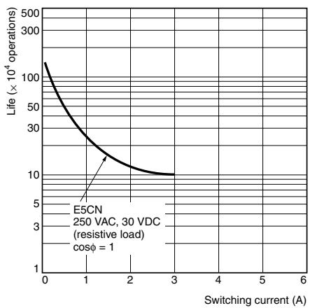
Note: Do not connect a DC load to a Controller with a Long-life Relay Output.
External Connections
- A voltage output (control output, for driving SSR) is not electrically insulated from the internal circuits. When using a grounding thermocouple, do not connect any of the control output terminals to ground. (If the control output terminals are connected to ground, errors will occur in the measured temperature values as a result of leakage current.)
- Consult with your OMRON representative before using the external power supply for the ES1B for any other purpose.
E5CN
Controllers
Control output 1
Long-life relay output
250 VAC, 3 A (resistive load)
Relay output
250 VAC, 3 A (resistive load)
Voltage output (for driving SSR)
12 VDC, 21 mA
Current output
0 to 20 mA DC
4 to 20 mA DC
Load: 600 Ω max.
A heater burnout alarm, heater short alarm, heater overcurrent alarm, or input alarm is sent to the output to which the alarm 1 function is assigned.
Option Units
Control output 2
Voltage output (for driving SSR)
12 VDC, 21 mA
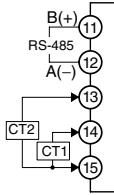
E53-CNHH03N2
Communications
(RS-485) and CT2
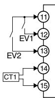
E53-CNHBN2
Event inputs
and CT
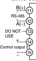
E53-CNQ03N2
Communications
(RS-485) and
Control Output 2
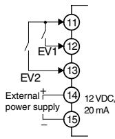
E53-CNPBN2
Event Inputs and
External Power Supply
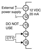
E53-CNPHN2
External Power
Supply and CT
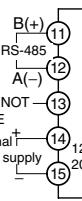
E53-CNP03N2
Communications (RS-485)
and External Power Supply
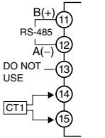
E53-CNH03N2
Communications
(RS-485) and CT
E53-CN03N2
Communications
(RS-485)
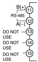
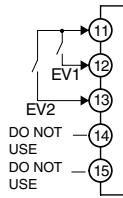
E53-CNBN2
Event inputs
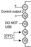
E53-CNQHN2
Control Output 2
and CT
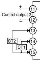
E53-CNQHHN2
Control Output 2
and CT2
E53-CNQBN2
Event Inputs and
Control Output 2
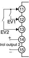
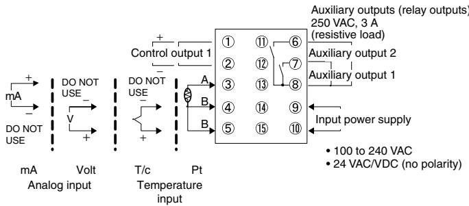
E5CN-U
Control output 1
Relay output
(three terminals used)
SPDT,250VAC,3A
(resistive load)
Voltage output
(for driving SSR)
12VDC 21mA
Current output
4 to 20 mA DC
0 to 20 mA DC
Load: 600 W max.
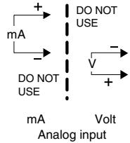
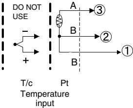
Auxiliary output
250 VAC, 3 A (resistive load)
(Relay outputs)
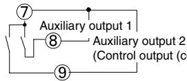
Note: For the Wiring Socket, purchase the P2CF-11 or PG3A-11 separately.
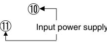
100 to 240 VAC
24 VAC/VDC (no polarity)
An input error is sent to the output to which the alarm 1 function is assigned.
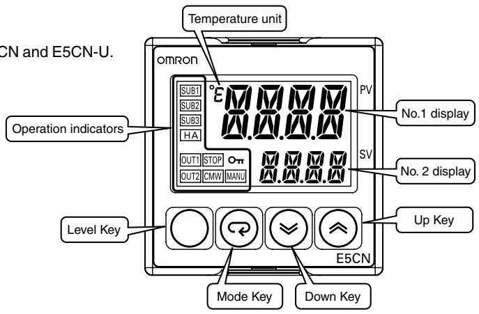
Nomenclature
E5CN
E5CN-U
The front panel is the same for the E5CN and E5CN-U.
Dimensions
(Unit: mm)
E5CN
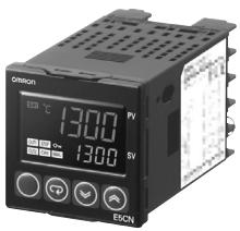
Terminal Models
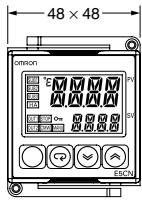
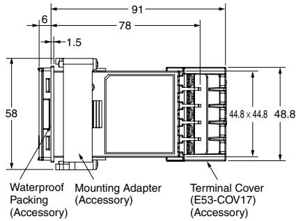
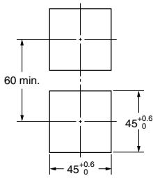
Panel Cutout
Mounted Separately
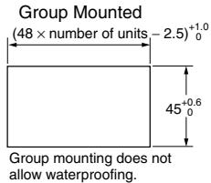
Recommended panel thickness is 1 to 5mm
- Group mounting is not possible in the vertical direction. (Maintain the specified mounting space between Controllers.)
- Mounting speed between Cent. 9:00-7
- To mount the Controller so that it is waterproof, insert the waterproof packing onto the Controller.
- When two or more Controllers are mounted, make sure that the surrounding temperature does not exceed the allowable operating temperature specified in the specifications.
Note: The terminal block cannot be removed.
E5CN-U
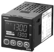
Plug-in Models
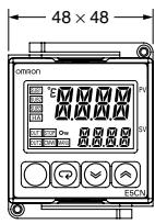
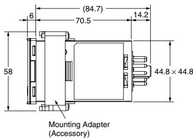
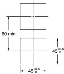
Panel Cutout
Mounted Separately
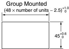
- Recommended panel thickness is 1 to 5 mm.
- Group mounting is not possible in the vertical direction. (Maintain the specified mounting space between Controllers.)
- When two or more Controllers are mounted, make sure that the surrounding temperature does not exceed the allowable operating temperature specified in the specifications.
Accessories (Order Separately)
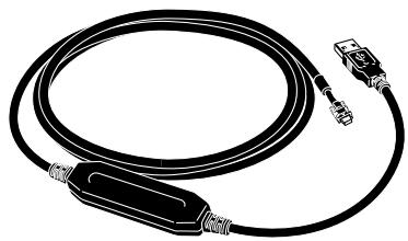
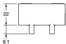
USB-Serial Conversion Cable
E58-CIFQ1

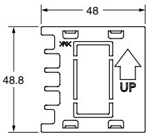
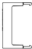
Terminal Cover E53-COV17
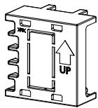
Note: The E53-COV10 cannot be used.
Waterproof Packing Y92S-29 (for DIN 48× 48
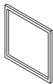
Order the Waterproof Packing separately if it becomes lost or damaged.
The Waterproof Packing can be used to achieve an IP66 degree of protection.
(Deterioration, shrinking, or hardening of the waterproof packing may occur depending on the operating environment. Therefore, periodic replacement is recommended to ensure the level of waterproofing specified in IP66. The time for periodic replacement depends on the operating environment. Be sure to confirm this point at your site.
Consider one year a rough standard. OMRON shall not be liable for the level of water resistance if the customer does not perform periodic replacement.)
The Waterproof Packing does not need to be attached if a waterproof structure is not required.
Current Transformers
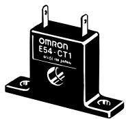
E54-CT1
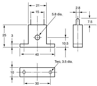
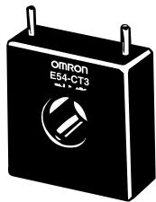
E54-CT3
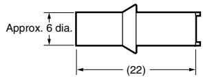
E54-CT3 Accessory
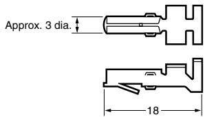
- Armature
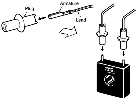
Connection Example
E54-CT1
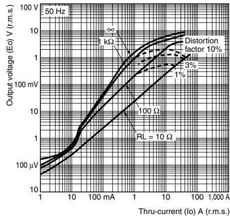
Thru-current (Io) vs. Output Voltage (Eo) (Reference Values)
Maximum continuous heater current: 50 A (50/60 Hz)
Number of windings: 400 ± 2
Winding resistance: 18 ± 2
E54-CT3
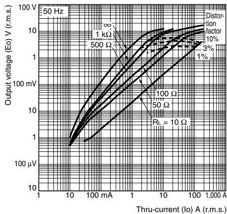
Thru-current (Io) vs. Output Voltage (Eo) (Reference Values)
Maximum continuous heater current: 120 A (50/60 Hz) (Maximum continuous heater current for the
Temperature Controller is 50 A.)
Number of windings: 400 ± 2
Winding resistance: 8 ± 0.8
Plug
Adapter
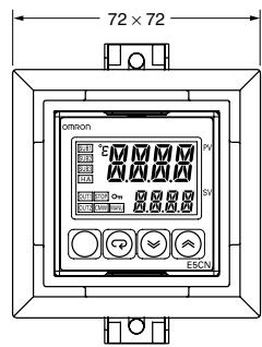
Y92F-45 Note: Use this Adapter when the panel has already been prepared for the E5B.
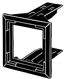
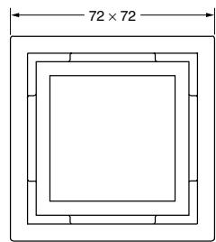
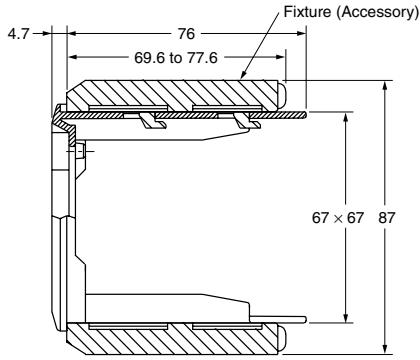
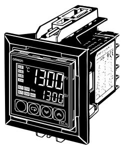
Mounted to E5CN
E5CN-U Wiring Socket
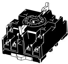
Front-connecting Socket
P2CF-11
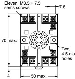
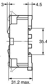
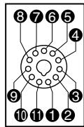
Terminal Layout/Internal Connections (Top View)
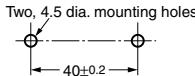
Mounting Holes
Note: Can also be mounted to a DIN track.
Note: A model with finger protection (P2CF-11-E) is also available.
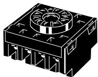
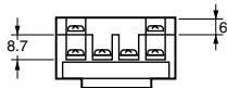
Back-connecting Socket
P3GA-11
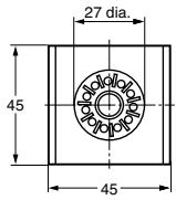
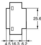
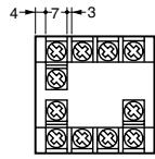
Terminal Layout/Internal Connections
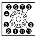
(Bottom View)
Note: 1. Using any other sockets will adversely affect accuracy. Use only the specified sockets.
2. A Protective Cover for finger protection (Y92A-48G) is also available.
Setting Levels Diagram
This diagram shows all of the setting levels. To move to the advanced function setting level and calibration level, you must enter passwords. Some parameters are not displayed depending on the protect level setting and the conditions of use.
Control stops when you move from the operation level to the initial setting level.
Basic Type
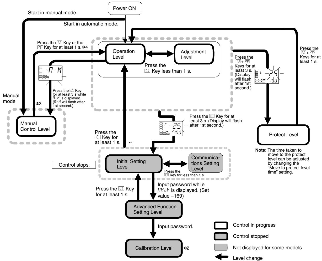
1. You can return to the operation level by executing a software reset.
2. It is not possible to move to other levels from the calibration level by operating the keys on the front panel. It can be done only by first turning OFF the power.
*3. From the manual control level, key operations can be used to move to the operation level only.
Error Displays (Troubleshooting)
When an error occurs, the No.1 display shows the error code. Take necessary measure according to the error code, referring the table below.
| No.1 display | Meaning | Action | Status at error | |
| Control output | Alarm output | |||
| S.ERR(S.Err) | Input error* | Check the wiring of inputs for miswiring, disconnections, and short-circuits and check the input type. | OFF | Operates as above the upper limit. |
| E333(E333) | A/D converter error | Turn the power OFF then back ON again. If the display remains the same, the controller must be repaired. If the display is restored to normal, then a probable cause can be external noise affecting the control system. Check for external noise. | OFF | OFF |
| E111(E111) | Memory error | Turn the power OFF then back ON again. If the display remains the same, the controller must be repaired. If the display is restored to normal, then a probable cause can be external noise affecting the control system. Check for external noise. | OFF | OFF |
Note: If the input value exceeds the display limit (-1999 to 9999), though it is within the control range, cccc will be displayed under -1999 and above 9999. Under these conditions, control output and alarm output will operate normally. For details on the control range, refer to the E5CN/E5AN/E5EN Digital Temperature Controllers User's Manual Basic Type (Cat. No. H156). *These errors are displayed only when the PV/SP is displayed. Errors are not displayed for other displays.
Parameters
Basic Type
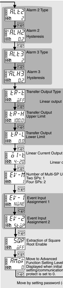
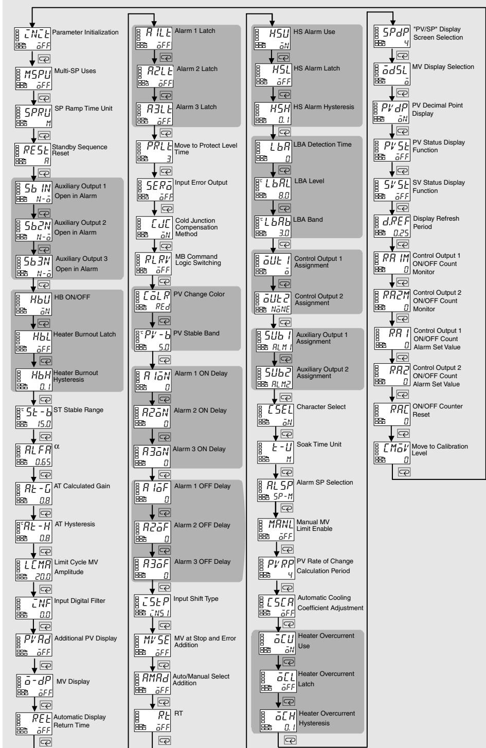
Some parameters are not displayed depending on the model of the Controller and parameter settings. For details, refer to the E5CN/E5AN/E5EN Digital Temperature Controllers User's Manual Basic Type (Cat. No. H156).
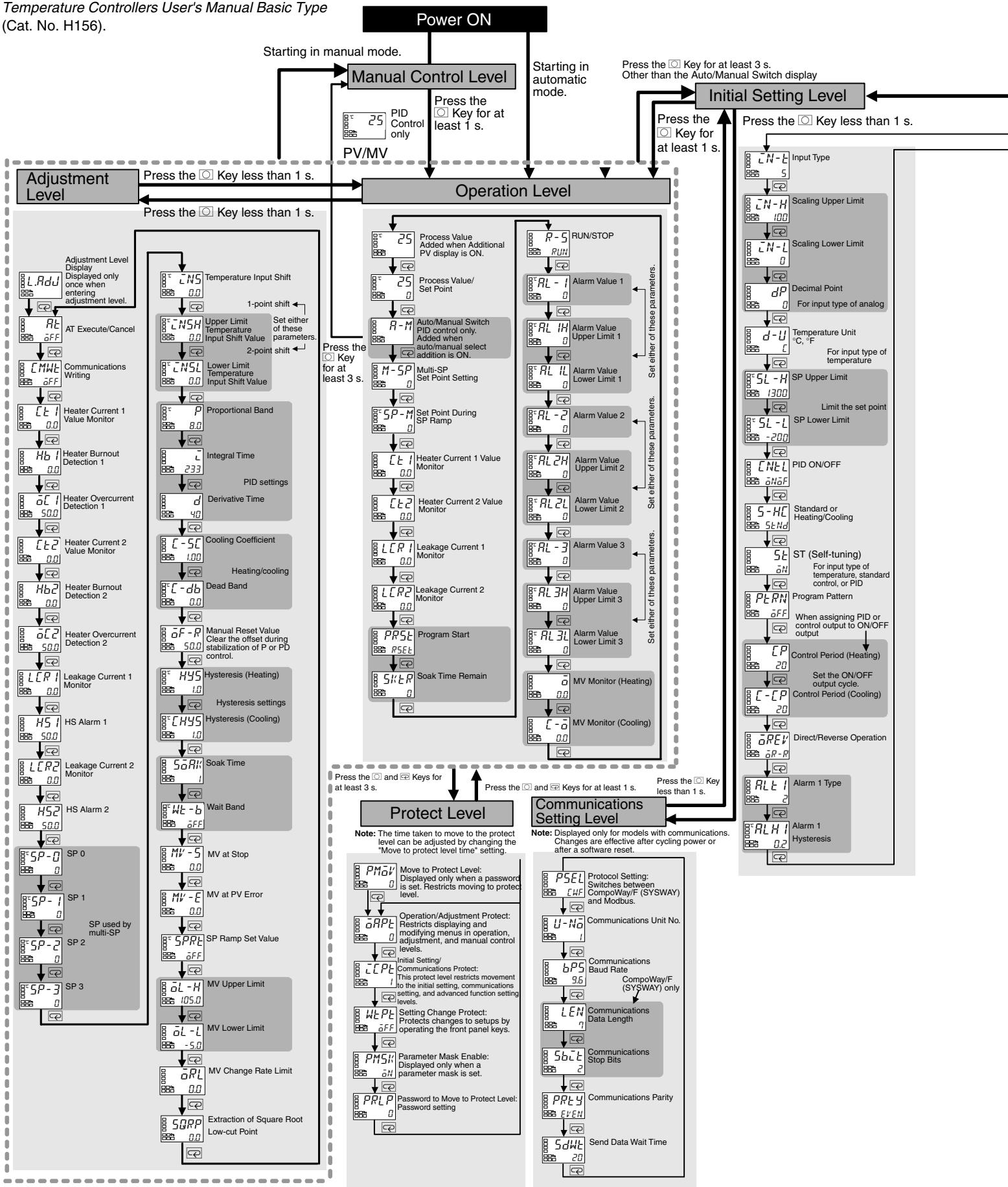
Press the for at least 1 s.
Advanced Function Setting Level
CAUTION
Do not touch the terminals while power is being supplied. Doing so may occasionally result in minor injury due to electric shock.

Do not allow pieces of metal, wire clippings, or fine metallic shavings or filings from installation to enter the product. Doing so may occasionally result in electric shock, fire, or malfunction.

Do not use the product where subject to flammable or explosive gas. Otherwise, minor injury from explosion may occasionally occur.

Do not leave the cable for the Support Software connected to the product. Malfunction may occur due to noise in the cable.

Do not use the Temperature Controller or Conversion Cable if it is damaged. Doing so may occasionally result in minor electric shock or fire.

Never disassemble, modify, or repair the product or touch any of the internal parts. Minor electric shock, fire, or malfunction may occasionally occur.

CAUTION - Risk of Fire and Electric Shock
a) This product is UL listed as Open Type Process Control Equipment. It must be mounted in an enclosure that does not allow fire to escape externally.
b) More than one disconnect switch may be required to de-energize the equipment before servicing the product.
c) Signal inputs are SELV, limited energy. 1
d) Caution: To reduce the risk of fire or electric shock, do not interconnect the outputs of different Class 2 circuits. 2

If the output relays are used past their life expectancy, contact fusing or burning may occasionally occur. Always consider the application conditions and use the output relays within their rated load and electrical life expectancy. The life expectancy of output relays varies considerably with the output load and switching conditions.

Tighten the terminal screws to between 0.74 and 0.90 N·m. *3 Loose screws may occasionally result in fire.

Set the parameters of the product so that they are suitable for the system being controlled. If they are not suitable, unexpected operation may occasionally result in property damage or accidents.

A malfunction in the product may occasionally make control operations impossible or prevent alarm outputs, resulting in property damage. To maintain safety in the event of malfunction of the product, take appropriate safety measures, such as installing a monitoring device on a separate line.

A semiconductor is used in the output section of long-life relays. If excessive noise or surge is impressed on the output terminals, a short-circuit failure is likely to occur. If the output remains shorted, fire will occur due to overheating of the heater or other cause. Take measures in the overall system to prevent excessive temperature increase and to prevent fire from spreading.

Do not allow pieces of metal or wire cuttings to get inside the cable connector for the Support Software. Failure to do so may occasionally result in minor electric shock, fire, or damage to equipment.

Do not allow dust and dirt to collect between the pins in the connector on the Conversion Cable. Failure to do so may occasionally result in fire.

When inserting the body of the Temperature Controller into the case, confirm that the hooks on the top and bottom are securely engaged with the case. If the body of the Temperature Controller is not inserted properly, faulty contact in the terminal section or reduced water resistance may occasionally result in fire or malfunction.

When connecting the Control Output Unit to the socket, press it in until there is no gap between the Control Output Unit and the socket. Otherwise contact faults in the connector pins may occasionally result in fire or malfunction.

1. An SELV circuit is one separated from the power supply with double insulation or reinforced insulation, that does not exceed 30 ~V r.m.s. and 42.4 ~V peak or 60 VDC.
2. A class 2 power supply is one tested and certified by UL as having the current and voltage of the secondary output restricted to specific levels.
*3. The tightening torque for E5CN-U is 0.5 N · m .
Precautions for Safe Use
-
Be sure to observe the following precautions to prevent malfunction or adverse affects on the performance or functionality of the product. Not doing so may occasionally result in faulty operation.
-
This product is specifically designed for indoor use only. Do not use this product in the following places:
- Places directly subject to heat radiated from heating equipment.
- Places subject to splashing liquid or oil atmosphere.
- Places subject to direct sunlight.
- Places subject to dust or corrosive gas (in particular, sulfide gas and ammonia gas).
- Places subject to intense temperature change.
- Places subject to icing and condensation.
-
Places subject to vibration and large shocks.
-
Use and store the product within the rated ambient temperature and humidity. Gang-mounting two or more Temperature Controllers, or mounting Temperature Controllers above each other may cause heat to built up inside the Temperature Controllers, which will shorten their service life. In such a case, use forced cooling by fans or other means of air ventilation to cool down the Temperature Controller
-
To allow heat to escape, do not block the area around the product. Do not block the ventilation holes on the product.
- Be sure to wire properly with correct polarity of terminals.
- Use the specified size (M3.5, width 7.2 mm or less) crimped terminals for wiring. To connect bare wires to the terminal block, use stranded or solid copper wires with a gage of AWG24 to AWG14 (equal to a cross-sectional area of 0.205 to 2.081 mm^2 ). (The stripping length is 5 to 6 mm.) Up to two wires of the same size and type or two crimp terminals can be inserted into a single terminal.
- Do not wire the terminals that are not used.
- To avoid inductive noise, keep the wiring for the product's terminal block away from power cables carry high voltages or large currents. Also, do not wire power lines together with or parallel to product wiring. Using shielded cables and using separate conduits or ducts is recommended.
Attach a surge suppressor or noise filter to peripheral devices that generate noise (in particular, motors, transformers, solenoids, magnetic coils, or other equipment that have an inductance component).
When a noise filter is used at the power supply, first check the voltage or current, and attach the noise filter as close as possible to the product.
Allow as much space as possible between the product and devices that generate powerful high frequencies (high-frequency welders, high-frequency sewing machines, etc.) or surge.
- Use this product within the rated load and power supply.
-
Make sure that the rated voltage is attained within two seconds of turning ON the power using a switch or relay contact. If the voltage is applied gradually, the power may not be reset or output malfunctions may occur.
10.Make sure that the Temperature Controller has 30 minutes or more to warm up after turning ON the power before starting actual control operations to ensure the correct temperature display. -
When executing self-tuning, turn ON power to the load (e.g., heater) at the same time as or before supplying power to the product. If power is turned ON to the product before turning ON power to the load, self-tuning will not be performed properly and optimum control will not be achieved.
12.A switch or circuit breaker must be provided close to the product. The switch or circuit breaker must be within easy reach of the operator, and must be marked as a disconnecting means for this unit. - Always turn OFF the power supply before pulling out the interior of the product, and never touch nor apply shock to the terminals or electronic components. When inserting the interior of the product, do not allow the electronic components to touch the case.
- Do not use paint thinner or similar chemical to clean with. Use standard grade alcohol.
- Design the system (e.g., control panel) considering the 2 seconds of delay that the product's output to be set after power ON.
- The output may turn OFF when shifting to certain levels. Take this into consideration when performing control.
- The number of EEPROM write operations is limited. Therefore, use RAM write mode when frequently overwriting data during communications or other operations.
- Always touch a grounded piece of metal before touching the Temperature Controller to discharge static electricity from your body.
19.Do not remove the terminal block. Doing so may result in failure or malfunction. - Control outputs (for driving SSR) that are voltage outputs are not isolated from the internal circuits. When using a grounded thermocouple, do not connect any of the control output terminals to ground. (Doing so may result in an unwanted circuit path, causing error in the measured temperature.)
- When replacing the body of the Temperature Controller, check the condition of the terminals. If corroded terminals are used, contact failure in the terminals may cause the temperature inside the Temperature Controller to increase, possibly resulting in fire. If the terminals are corroded, replace the case as well.
22.Use suitable tools when taking the Temperature Controller apart for disposal. Sharp parts inside the Temperature Controller may cause injury. - Before connecting an Output Unit, confirm the specifications and thoroughly read relevant information in the datasheet and manual for the Temperature Controller.
- Check the orientation of the connectors on the Conversion Cable before connecting the Conversion Cable. Do not force a connector if it does not connect smoothly. Using excessive force may damage the connector.
- Do not place heavy object on the Conversion Cable, bend the cable past its natural bending radius, or pull on the cable with undue force.
- Do not connect or disconnect the Conversion Cable while communications are in progress. Product faults or malfunction may occur.
27.Make sure that the Conversion Cable's metal components are not touching the external power terminals.
28.Do not touch the connectors on the Conversion Cable with wet hands. Electrical shock may result. - Before using infrared communications, correctly attach the enclosed Mounting Adapter to the cable for the Support Software. When connecting the infrared port on the cable to the Support Software into the Adapter, insert the connector to the specified line. Communications may not be possible if the connector is not connected properly.
Precautions for Correct Use
Service Life
- Use the product within the following temperature and humidity ranges: Temperature: -10 to 55^ (with no icing or condensation) Humidity: 25% to 85%
If the product is installed inside a control board, the ambient temperature must be kept to under 55^ , including the temperature around the product.
- The service life of electronic devices like Temperature Controllers is determined not only by the number of times the relay is switched but also by the service life of internal electronic components. Component service life is affected by the ambient temperature: the higher the temperature, the shorter the service life and, the lower
the temperature, the longer the service life. Therefore, the service life can be extended by lowering the temperature of the Temperature Controller.
3. When two or more Temperature Controllers are mounted horizontally close to each other or vertically next to one another, the internal temperature will increase due to heat radiated by the Temperature Controllers and the service life will decrease. In such a case, use forced cooling by fans or other means of air ventilation to cool down the Temperature Controllers. When providing forced cooling, however, be careful not to cool down the terminals sections alone to avoid measurement errors.
Measurement Accuracy
- When extending or connecting the thermocouple lead wire, be sure to use compensating wires that match the thermocouple types.
- When extending or connecting the lead wire of the platinum resistance thermometer, be sure to use wires that have low resistance and keep the resistance of the three lead wires the same.
- Mount the product so that it is horizontally level.
- If the measurement accuracy is low, check to see if input shift has been set correctly.
Waterproofing
The degree of protection is as shown below. Sections without any specification on their degree of protection or those with IP 0 are not waterproof.
Front panel: IP66
Rear case: IP20, Terminal section: IP00
(E5CN-U: Front panel: IP50, rear case: IP20, terminals: IP00)
Operating Precautions
- It takes approximately two seconds for the outputs to turn ON from after the power supply is turned ON. Due consideration must be given to this time when incorporating Temperature Controllers in a sequence circuit.
- When using self-tuning, turn ON power for the load (e.g., heater) at the same time as or before supplying power to the Temperature Controller. If power is turned ON for the Temperature Controller before turning ON power for the load, self-tuning will not be performed properly and optimum control will not be achieved.
- When starting operation after the Temperature Controller has warmed up, turn OFF the power and then turn it ON again at the same time as turning ON power for the load. (Instead of turning the Temperature Controller OFF and ON again, switching from STOP mode to RUN mode can also be used.)
- Avoid using the Controller in places near a radio, television set, or wireless installing. These devices can cause radio disturbances which adversely affect the performance of the Controller.
Others
- The disk that is included with the Conversion Cable is designed for a computer CD-ROM driver. Never attempt to play the disk in a general-purpose audio player.
- Do not connect or disconnect the Conversion Cable connector repeatedly over a short period of time. The computer may malfunction.
- After connecting the Conversion Cable to the computer, check the COM port number before starting communications. The computer requires time to recognize the cable connection. This delay does not indicate failure.
- Do not connect the Conversion Cable through a USB hub. Doing so may damage the Conversion Cable.
- Do not use an extension cable to extend the Conversion Cable length when connecting to the computer. Doing so may damage the Conversion Cable.
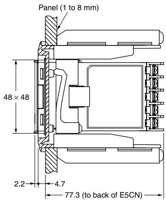
Mounting
Mounting to a Panel
For waterproof mounting, waterproof packing must be installed on the Controller. Waterproofing is not possible when group mounting several Controllers. Waterproof packing is not necessary when there is no need for the waterproofing function.
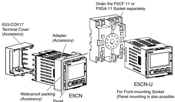
- The Panel Mounting Adapter is also included with the E5CN-U. There is no waterproof packing included with the E5CN-U.
- Insert the E5CN/E5CN-U into the mounting hole in the panel.
- Push the adapter from the terminals up to the panel, and temporarily fasten the E5CN/E5CN-U.
- Tighten the two fastening screws on the adapter. Alternately tighten the two screws little by little to maintain a balance. Tighten the screws to a torque of 0.29 to 0.39N· m .
Mounting the Terminal Cover
Make sure that the "UP" mark is facing up, and then attach the E53-COV17 Terminal Cover to the holes on the top and bottom of the Temperature Controller.
Removing the Temperature Controller from the Case
The Temperature Controller can be removed from the case to perform maintenance without removing the terminal leads. This is possible for only the E5CN, E5AN, and E5EN, and not for the E5CN-U. Check the specifications of the case and Temperature Controller before removing the Temperature Controller from the case.
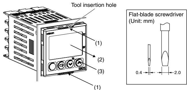
- Insert a flat-blade screwdriver into the two tool insertion holes (one on the top and one on the bottom) to release the hooks.
- Insert the flat-blade screwdriver in the gap between the front panel and rear case, and pull out the front panel slightly. Hold the top and bottom of the front panel and carefully pull it out toward you, without applying unnecessary force.
- When inserting the body of the Temperature Controller into the case, make sure the PCBs are parallel to each other, make sure that the sealing rubber is in place, and press the E5CN toward the rear case into position. While pushing the E5CN into place, push down on the hooks on the top and bottom surfaces of the rear case so that the hooks are securely locked in place. Be sure that electronic components do not come into contact with the case.
Precautions when Wiring
- Separate input leads and power lines in order to prevent external noise.
- Use wires with a gage of AWG24 (cross-sectional area: 0.205 mm^2 ) to AWG14 (cross-sectional area: 2.081 mm^2 ) twisted-pair cable (stripping length: 5 to 6 mm).
- Use crimp terminals when wiring the terminals.
- Tighten the terminal screws to a torque of 0.74 to 0.90N· m , however the terminal screws on the E5CN-U must be tightened to a torque of 0.5N· m .
- Use the following types of crimp terminals for M3.5 screws.
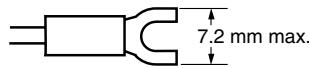
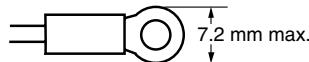
- Do not remove the terminal block. Doing so will result in malfunction or failure.
Warranty and Application Considerations
| Read and Understand This Catalog |
| Please read and understand this catalog before purchasing the products. Please consult your OMRON representative if you have any questions or comments. |
| Warranty and Limitations of Liability |
| WARRANTY OMRON's exclusive warranty is that the products are free from defects in materials and workmanship for a period of one year (or other period if specified) from date of sale by OMRON. OMRON MAKES NO WARRANTY OR REPRESENTATION, EXPRESS OR IMPLIED, REGARDING NON-INFRINGEMENT, MERCHANTABILITY, OR FITNESS FOR PARTICULAR PURPOSE OF THE PRODUCTS. ANY BUYER OR USER ACKNOWLEDGES THAT THE BUYER OR USER ALONE HAS DETERMINED THAT THE PRODUCTS WILL SUITABLY MEET THE REQUIREMENTS OF THEIR INTENDED USE. OMRON DISCLAIMS ALL OTHER WARRANTYES, EXPRESS OR IMPLIED. |
| LIMITATIONS OF LIABILITY OMRON SHALL NOT BE RESPONSIBLE FOR SPECIAL, INDIRECT, OR CONSEQUENTIAL DAMAGES, LOSS OF PROFITS, OR COMMERCIAL LOSS IN ANY WAY CONNECTED WITH THE PRODUCTS, WHETHER SUCH CLAIM IS BASED ON CONTRACT, WARRANTY, NEGLIGENCE, OR STRICT LIABILITY. In no event shall the responsibility of OMRON for any act exceed the individual price of the product on which liability is asserted. IN NO EVENT SHALL OMRON BE RESPONSIBLE FOR WARRANTY, REPAIR, OR OTHER CLAIMS REGARDING THE PRODUCTS UNLESS OMRON'S ANALYSIS CONFIRMS THAT THE PRODUCTS WERE PROPERLY HANDLED, STORED, INSTALLED, AND MAINTAINED AND NOT SUBJECT TO CONTAMINATION, ABUSE, MISUSE, OR INAPPROPRIATE MODIFICATION OR REPAIR. |
| Application Considerations |
| SUITABILITY FOR USE OMRON shall not be responsible for conformity with any standards, codes, or regulations that apply to the combination of products in the customer's application or use of the products. Take all necessary steps to determine the suitability of the product for the systems, machines, and equipment with which it will be used. Know and observe all prohibitions of use applicable to this product. NEVER USE THE PRODUCTS FOR AN APPLICATION INVOLVING SERIOUS RISK TO LIFE OR PROPERTY WITHOUT ENSURING THAT THE SYSTEM AS A WHOLE HAS BEEN DESIGNED TO ADDRESS THE RISKS, AND THAT THE OMRON PRODUCTS ARE PROPERLY RATED AND INSTALLED FOR THE INTENDED USE WITHIN THE OVERALL EQUIPMENT OR SYSTEM. |
| Disclaimers |
| PERFORMANCE DATA Performance data given in this catalog is provided as a guide for the user in determining suitability and does not constitute a warranty. It may represent the result of OMRON's test conditions, and the users must correlate it to actual application requirements. Actual performance is subject to the OMRON Warranty and Limitations of Liability. |
| CHANGE IN SPECIFICATIONS Product specifications and accessories may be changed at any time based on improvements and other reasons. Consult with your OMRON representative at any time to confirm actual specifications of purchased product. |
| DIMENSIONS AND WEIGHTS Dimensions and weights are nominal and are not to be used for manufacturing purposes, even when tolerances are shown. |
ALL DIMENSIONS SHOWN ARE IN MILLIMETERS.
To convert millimeters into inches, multiply by 0.03937. To convert grams into ounces, multiply by 0.03527.
Cat. No. H04E-EN-01
In the interest of product improvement, specifications are subject to change without notice.
OMRON EUROPE B.V.
Wegalaan 67-69,
NL-2132 JD, Hoofddorp,
The Netherlands
Phone: +31 23 568 13 00
Fax: +31 23 568 13 88
www.industrial.omron.eu
- Basic-type Digital Temperature Controller
- E5CN/E5CN-U (48 x 48 mm)
- New 48 x 48-mm Basic Temperature Controller with Enhanced Functions and Performance. Improved Indication Accuracy and Preventive Maintenance Function.
- Model Number Structure
- Model Number Legend Controllers
- Option Units
- Ordering Information
- Model Number Legend (Plug-in-type Controllers)
- E5CN-2U 1234
- Output Type
- Number of Alarms
- Input Type
- Plug-in type
- Accessories (Order Separately)
- USB-Serial Conversion Cable
- Input Ranges
- Thermocouple/Platinum Resistance Thermometer (Universal Inputs)
- Models with Analog Inputs
- Alarm Outputs
- Electrical Life Expectancy Curve for Relays (Reference Values)
- External Connections
- E5CN
- Controllers
- Control output 1
- Control output 2
- E5CN-U
- Nomenclature
- Dimensions
- Terminal Cover E53-COV17
- Waterproof Packing Y92S-29 (for DIN 48× 48
- Current Transformers
- E54-CT3 Accessory
- E54-CT1
- Thru-current (Io) vs. Output Voltage (Eo) (Reference Values)
- E54-CT3
- Adapter
- E5CN-U Wiring Socket
- Setting Levels Diagram
- Basic Type
- Error Displays (Troubleshooting)
- Parameters
- Advanced Function Setting Level
- CAUTION
- CAUTION - Risk of Fire and Electric Shock
- Precautions for Safe Use
- Precautions for Correct Use
- Service Life
- Measurement Accuracy
- Waterproofing
- Operating Precautions
- Others
- Mounting
- Mounting to a Panel
- Mounting the Terminal Cover
- Removing the Temperature Controller from the Case
- Precautions when Wiring
- Warranty and Application Considerations
- OMRON EUROPE B.V.
Marque : OMRON
Modèle : E5CN-U
Catégorie : Contrôleur de température