
E5AR - Contrôleur de température OMRON - Notice d'utilisation et mode d'emploi gratuit
Retrouvez gratuitement la notice de l'appareil E5AR OMRON au format PDF.


| Type de produit | Contrôleur de température avec communication DeviceNet |
| Dimensions (L x H x P) | 96 x 96 x 111 mm |
| Poids | Environ 400 g |
| Alimentation | 100-240 VAC ou 24 VAC/DC selon modèle |
| Consommation | 22 VA max. (AC), 10 W max. (DC) |
| Affichage | LED 7 segments (PV, SV, MV) |
| Nombre de voies | 1 à 4 voies selon modèle |
| Type d'entrée | Thermocouple, PT100, courant (4-20 mA), tension (0-10 V) |
| Types de sortie | Tension impulsionnelle (12 V 40 mA), courant linéaire (4-20 mA), relais (250 VAC 1 A) |
| Communication | DeviceNet (remote I/O et messages explicites) |
| Fonctions de contrôle | PID, auto-ajustement, rampe/soak, position proportionnelle |
| Fonctions d'alarme | Jusqu'à 4 alarmes configurables (valeur, limite haute/basse) |
| Température ambiante | -10 à 55°C (stockage -25 à 65°C) |
| Humidité ambiante | 25 à 85% HR (sans condensation) |
| Nettoyage | Alcool commercial, chiffon doux. Ne pas utiliser de solvants. |
| Sécurité | Ne pas ouvrir, risque de choc électrique. Utiliser une alimentation avec isolation renforcée. |
| Réparabilité | Non réparable par l'utilisateur. Retourner au fabricant pour maintenance. |
FOIRE AUX QUESTIONS - E5AR OMRON
Questions des utilisateurs sur E5AR OMRON
0 question sur cet appareil. Repondez a celles que vous connaissez ou posez la votre.
Poser une nouvelle question sur cet appareil
Téléchargez la notice de votre Contrôleur de température au format PDF gratuitement ! Retrouvez votre notice E5AR - OMRON et reprennez votre appareil électronique en main. Sur cette page sont publiés tous les documents nécessaires à l'utilisation de votre appareil E5AR de la marque OMRON.
MODE D'EMPLOI E5AR OMRON
OMRON
OMRON Corporation
Industrial Automation Company
Industrial Devices and Components Division H.Q.
Measuring Components Department
Shiokoji Horikawa, Shimogyo-ku,
Kyoto, 600-8530 Japan
Tel: (81)75-344-7080/Fax: (81)75-344-7189
Regional Headquarters
OMRON EUROPE B.V.
Wegalaan 67-69, NL-2132 JD Hoofddorp
The Netherlands
Tel: (31)2356-81-300/Fax: (31)2356-81-388
OMRON ELECTRONICS LLC
1 East Commerce Drive, Schaumburg, IL 60173
U.S.A.
Tel: (1)847-843-7900/Fax: (1)847-843-8568
OMRON ASIA PACIFIC PTE. LTD.
83 Clemenceau Avenue,
11-01, UE Square,
239920 Singapore
Tel: (65)6835-3011/Fax: (65)6835-2711
OMRON CHINA CO., LTD.
BEIJING OFFICE
Room 1028, Office Building,
Beijing Capital Times Square
No. 88 West Chang'an Road,
Beijing, 100031 China
Tel: (86)10-8391-3005/Fax: (86)10-8391-3688
Authorized Distributor:
ONRON
E5AR/ER Digital Controller DeviceNet Communications
User's Manual Cat. No. H124-E1-01
E5AR/ER
Digital Controller
DeviceNet
Communications
User's Manual
E5AR/ER
Digital Controller
DeviceNet Communications
User's Manual
Produced February 2004
Notice:
OMRON products are manufactured for use according to proper procedures by a qualified operator and only for the purposes described in this manual.
This manual describes the functions, performance, and application methods needed for optimum use of the E5AR/E5ER-DRT Digital Controllers.
Please observe the following items when using the E5AR/E5ER-DRT Digital Controllers.
- This product is designed for use by qualified personnel with a knowledge of electrical systems.
- Read this manual carefully and make sure you understand it well to ensure that you are using the E5AR/E5ER-DRT Digital Controllers correctly.
- Keep this manual in a safe location so that it is available for reference when required.
Visual Aids
The following headings appear in the left column of the manual to help you locate different types of information.
Note Indicates information of particular interest for efficient and convenient operation of the product.
1,2,3... 1. Indicates lists of one sort or another, such as procedures, checklists, etc.
Trademarks
• COMBICON is a registered trademark of Phoenix Contact.
• DeviceNet is a registered trademark of the Open DeviceNet Vendors Association, Inc.
- Other product names and company names that appear in this manual are the trademarks or registered trademarks of the respective companies.
© OMRON, 2004
All rights reserved. No part of this publication may be reproduced, stored in a retrieval system, or transmitted, in any form, or by any means, mechanical, electronic, photocopying, recording, or otherwise, without the prior written permission of OMRON.
No patent liability is assumed with respect to the use of the information contained herein. Moreover, because OMRON is constantly striving to improve its high-quality products, the information contained in this manual is subject to change without notice. Every precaution has been taken in the preparation of this manual. Nevertheless, OMRON assumes no responsibility for errors or omissions. Neither is any liability assumed for damages resulting from the use of the information contained in this publication.
| Read and Understand this Manual |
| Please read and understand this manual before purchasing the product. Please consult your OMRON representative if you have any questions or comments. |
Warranty and Limitations of Liability
WARRANTY
OMRON's exclusive warranty is that the products are free from defects in materials and workmanship for a period of one year (or other period if specified) from date of sale by OMRON.
OMRON MAKES NO WARRANTY OR REPRESENTATION, EXPRESS OR IMPLIED, REGARDING NON-INFRINGEMENT, MERCHANTABILITY, OR FITNESS FOR PARTICULAR PURPOSE OF THE PRODUCTS. ANY BUYER OR USER ACKNOWLEDGES THAT THE BUYER OR USER ALONE HAS DETERMINED THAT THE PRODUCTS WILL SUITABLY MEET THE REQUIREMENTS OF THEIR INTENDED USE. OMRON DISCLAIMS ALL OTHER WARRANTIES, EXPRESS OR IMPLIED.
LIMITATIONS OF LIABILITY
OMRON SHALL NOT BE RESPONSIBLE FOR SPECIAL, INDIRECT, OR CONSEQUENTIAL DAMAGES, LOSS OF PROFITS OR COMMERCIAL LOSS IN ANY WAY CONNECTED WITH THE PRODUCTS, WHETHER SUCH CLAIM IS BASED ON CONTRACT, WARRANTY, NEGLIGENCE, OR STRICT LIABILITY.
In no event shall the responsibility of OMRON for any act exceed the individual price of the product on which liability is asserted.
IN NO EVENT SHALL OMRON BE RESPONSIBLE FOR WARRANTY, REPAIR, OR OTHER CLAIMS REGARDING THE PRODUCTS UNLESS OMRON'S ANALYSIS CONFIRMS THAT THE PRODUCTS WERE PROPERLY HANDLED, STORED, INSTALLED, AND MAINTAINED AND NOT SUBJECT TO CONTAMINATION, ABUSE, MISUSE, OR INAPPROPRIATE MODIFICATION OR REPAIR.
Application Considerations
SUITABILITY FOR USE
OMRON shall not be responsible for conformity with any standards, codes, or regulations that apply to the combination of products in the customer's application or use of the products.
At the customer's request, OMRON will provide applicable third party certification documents identifying ratings and limitations of use that apply to the products. This information by itself is not sufficient for a complete determination of the suitability of the products in combination with the end product, machine, system, or other application or use.
The following are some examples of applications for which particular attention must be given. This is not intended to be an exhaustive list of all possible uses of the products, nor is it intended to imply that the uses listed may be suitable for the products.
- Outdoor use, uses involving potential chemical contamination or electrical interference, or conditions or uses not described in this manual.
- Nuclear energy control systems, combustion systems, railroad systems, aviation systems, medical equipment, amusement machines, vehicles, safety equipment, and installations subject to separate industry or government regulations.
- Systems, machines, and equipment that could present a risk to life or property.
Please know and observe all prohibitions of use applicable to the products.
NEVER USE THE PRODUCTS FOR AN APPLICATION INVOLVING SERIOUS RISK TO LIFE OR PROPERTY WITHOUT ENSURING THAT THE SYSTEM AS A WHOLE HAS BEEN DESIGNED TO ADDRESS THE RISKS, AND THAT THE OMRON PRODUCTS ARE PROPERLY RATED AND INSTALLED FOR THE INTENDED USE WITHIN THE OVERALL EQUIPMENT OR SYSTEM.
PROGRAMMABLE PRODUCTS
OMRON shall not be responsible for the user's programming of a programmable product, or any consequence thereof.
| Disclaimers |
| CHANGE IN SPECIFICATIONSProduct specifications and accessories may be changed at any time based on improvements and other reasons.It is our practice to change model numbers when published ratings or features are changed, or when significant construction changes are made. However, some specifications of the products may be changed without any notice. When in doubt, special model numbers may be assigned to fix or establish key specifications for your application on your request. Please consult with your OMRON representative at any time to confirm actual specifications of purchased products. |
| DIMENSIONS AND WEIGHTSDimensions and weights are nominal and are not to be used for manufacturing purposes, even when tolerances are shown. |
| PERFORMANCE DATAPerformance data given in this manual is provided as a guide for the user in determining suitability and does not constitute a warranty. It may represent the result of OMRON's test conditions, and the users must correlate it to actual application requirements. Actual performance is subject to the OMRON Warranty and Limitations of Liability. |
| ERRORS AND OMISSIONSThe information in this manual has been carefully checked and is believed to be accurate; however, no responsibility is assumed for clerical, typographical, or proofreading errors, or omissions. |
Precautions for Safe Use
● Definition of Safety Notices and Information
The following notation is used in this manual to provide precautions required to ensure safe usage of the product.
The safety precautions that are provided are extremely important to safety. Always read and heed the information provided in all safety precautions.
The following notation is used.

WARNING
Indicates a potentially hazardous situation which, if not avoided, will result in minor or moderate injury, or may result in serious injury or death. Additionally there may be significant property damage.

CAUTION
Indicates a potentially hazardous situation which, if not avoided, may result in minor or moderate injury or in property damage.
Symbols
| Symbol | Meaning | |
| Caution |  | General CautionIndicates non-specific general cautions, warnings, and dangers. |
 | Electrical Shock CautionIndicates possibility of electric shock under specific conditions. | |
| Prohibition |  | General ProhibitionIndicates non-specific general prohibitions. |
| Mandatory Caution |  | General CautionIndicates non-specific general cautions, warnings, and dangers. |

WARNING
Always provide protective circuits in the network. Without protective circuits, malfunctions may possibly result in accidents that cause serious injury or significant property damage. Provide double or triple safety measures in external control circuits, such as emergency stop circuits, interlock circuits, or limit circuits, to ensure safety in the system if an abnormality occurs due to malfunction of the product or another external factor affecting the product's operation.


CAUTION
| Do not attempt to disassemble, repair, or modify the product. Doing so may occasionally result in minor injury due to electric shock. |  |
| Do not touch the terminals, or electronic components or patterns on the PCB within 1 minute after turning OFF the power. Doing so may occasionally result in minor injury due to electric shock. |  |
| Do not allow pieces of metal, wire clippings, or fine metallic shavings or filings from installation to enter the product. Doing so may occasionally result in electric shock, fire, or malfunction. |  |
| Do not use the product in locations where flammable or explosive gases are present. Doing so may occasionally result in minor or moderate explosion, causing minor or moderate injury, or property damage. |  |
| Do not attempt to disassemble, repair, or modify the product. Doing so may occasionally result in minor or moderate injury due to electric shock. |  |
| Tighten the screws on the terminal block and the connector locking screws securely using a tightening torque within the following ranges. Loose screws may occasionally cause fire, resulting in minor or moderate injury, or damage to the equipment.Terminal block screws: 0.40 to 0.56 N·mConnector locking screws: 0.25 to 0.30 N·m |  |
| Perform correct setting of the product according to the application. Failure to do so may occasionally cause unexpected operation, resulting in minor or moderate injury, or damage to the equipment. |  |
| Ensure safety in the event of product failure by taking safety measures, such as installing a separate overheating prevention alarm system. Product failure may occasionally prevent control, or operation of alarm outputs, resulting in damage to the connected facilities and equipment. |  |
| Do not use the equipment for measurements within Measurement Categories II, III, or IV (according to IEC61010-1). Doing so may occasionally cause unexpected operation, resulting in minor or moderate injury, or damage to the equipment. Use the equipment for measurements only within the Measurement Category for which the product is designed. |  |
| The service life of the output relays depends on the switching capacity and switching conditions. Consider the actual application conditions and use the product within the rated load and electrical service life. Using the product beyond its service life may occasionally result in contact welding or burning. |  |
| CAUTION | |
| Make sure that the product will not be adversely affected if the DeviceNet cycle time is lengthened as a result of changing the program with online editing. Extending the cycle time may cause unexpected operation, occasionally resulting in minor or moderate injury, or damage to the equipment. |  |
| Before transferring programs to other nodes or changing I/O memory of other nodes, check the nodes to confirm safety. Changing the program or I/O memory of other nodes may occasionally cause unexpected operation, resulting in minor or moderate injury, or damage to the equipment. |  |
Precautions for Safe Use
- Use and store the product within the specified ambient temperature and humidity ranges. If several products are mounted side-by-side or arranged in a vertical line, the heat dissipation will cause the internal temperature of the products to rise, shortening the service life. If necessary, cool the products using a fan or other cooling method.
- Provide sufficient space around the product for heat dissipation. Do not block the vents on the product.
- Use the product within the noted supply voltage and rated load.
- Be sure to confirm the name and polarity for each terminal before wiring the terminal block and connectors.
- Do not connect anything to unused terminals.
- Use the specified size of crimp terminals (M3, width: 5.8 mm max.) for wiring the terminal block.
- To connect bare wires to the terminal block, use AWG22 to AWG14 (cross-sectional area: 0.326 to 2.081 mm ^2 ) to wire the power supply terminals and AWG28 to AWG16 (cross-sectional area: 0.081 to 1.309 mm ^2 ) for other terminals. (Length of exposed wire: 6 to 8 mm)
- Ensure that the rated voltage is achieved no longer than 2 s after turning the power ON.
- Turn OFF the power first before drawing out the product. Never touch the terminals or the electronic components, or subject them to physical shock. When inserting the product, do not allow the electronic components to contact the case.
- Do not remove the inner circuit board.
- Output turns OFF when shifting to the initial setting level in certain modes. Take this into consideration when setting up the control system.
- Allow the product to warm up for at least 30 minutes after the power is turned ON.
- Install surge absorbers or noise filters in devices near the product that generate noise (in particular, devices with an inductance component, such as motors, transformers, solenoids, and magnetic coils). If a noise filter is used for the power supply, check the voltage and current, and install the noise filter as close as possible to the product. Separate the product as far as possible from devices generating strong high-frequency noise (e.g., high-frequency welders and high-frequency sewing machines) or surges. Do not tie noise filter input/output wires together.
- Keep the wiring for the product's terminal block and connector separate from high-voltage, high-current power lines to prevent inductive noise. Do not run the wiring parallel to or in the same cable as power lines. The influence of noise can also be reduced by using separate wiring ducts or shield lines.
-
Install an external switch or circuit breaker and label them clearly so that the operator can quickly turn OFF the power.
-
Do not use the product in the following locations.
-
Locations where dust or corrosive gases (in particular, sulfuric or ammonia gas) are present.
- Locations where icing or condensation may occur.
- Locations exposed to direct sunlight.
- Locations subject to excessive shock or vibration.
- Locations where the product may come into contact with water or oil.
- Locations subject to direct radiant heat from heating equipment.
-
Locations subject to extreme temperature changes.
-
Cleaning: Do not use thinners. Use commercially available alcohol.
-
Use the specified cables for the communications lines and stay within the specified DeviceNet communications distances.
-
Do not pull the DeviceNet communications cables with excessive force or bend them past their natural bending radius.
-
Do not connect or remove connectors while the DeviceNet power is being supplied. Doing so will cause product failure or malfunction.
EC Directives
- EMC Directives
Concepts
EMC Directives
OMRON devices that comply with EC Directives also conform to the related EMC standards so that they can be more easily built into other devices or the overall machine. The actual products have been checked for conformity to EMC standards. Whether the products conform to the standards in the system used by the customer, however, must be checked by the customer.
EMC-related performance of the OMRON devices that comply with EC Directives will vary depending on the configuration, wiring, and other conditions of the equipment or control panel on which the OMRON devices are installed. The customer must, therefore, perform the final check to confirm that devices and the overall machine conform to EMC standards.
Conformance to EC Directives
The E5AR/E5ER-DRT Digital Controllers comply with EC Directives. To ensure that the machine or device in which the Unit is used complies with EC Directives, the Unit must be installed as follows:
1,2,3...
- You must use reinforced insulation or double insulation for the DC power supplies used for the communications power supply, internal power supply, and I/O power supplies.
- Units complying with EC Directives also conform to the Common Emission Standard (EN61326). Radiated emission characteristics (10-m regulations) may vary depending on the configuration of the control panel used, other devices connected to the control panel, wiring, and other conditions. You must therefore confirm that the overall machine or equipment complies with EC Directives.
The following example shows one means of reducing noise.
1,2,3...
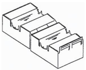
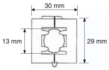
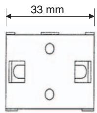
- Noise from the communications cable can be reduced by installing a ferrite core on the communications cable within 10 cm of the DeviceNet Master Unit.
Ferrite Core (Data Line Filter): 0443-164151 (manufactured by Fair-Rite Products Co., Ltd.)
natural_image
Isometric line drawing of a three-tiered rectangular container or housing (no text or symbols)| Impedance specifications | |
| 25 MHz | 105 Ω |
| 100 MHz | 190 Ω |
- Wire the control panel with as thick and short electric lines as possible and ground to 100 min .
- Keep DeviceNet communications cables as short as possible and ground to 100 min.
TABLE OF CONTENTS
SECTION 1
Overview 1-1
1-1 Features 1-2
1-2 Specifications.... 1-5
SECTION 2
Operating Procedures.... 2-1
2-1 Introduction 2-2
2-2 Functions Supported Only by the E5AR/ER-DRT 2-4
SECTION 3
Parts, Installation, and Wiring 3-1
3-1 Part Names and Functions 3-2
3-2 How to Use the Terminals 3-6
3-3 DeviceNet Communications Cables Wiring 3-15
SECTION 4
Remote I/O Communications 4-1
4-1 Overview 4-2
4-2 I/O Allocation 4-2
4-3 Ladder Programming Examples 4-13
SECTION 5
Explicit Message Communications .... 5-1
5-1 Overview of Explicit Message Communications 5-2
5-2 Sending CompoWay/F Commands to the Digital Controller 5-4
5-3 Explicit Messages Specific to DeviceNet-compatible Digital Controllers ..... 5-6
SECTION 6
Communications Performance 6-1
6-1 Remote I/O Communications Performance.... 6-2
6-2 Message Communications Performance 6-6
SECTION 7
Troubleshooting and Maintenance 7-1
7-1 Indicators and Error Processing.... 7-2
7-2 Maintenance.... 7-3
TABLE OF CONTENTS
Appendices
A Detailed DeviceNet Specifications A-1
B Mounted Objects B-1
C DeviceNet Connection Hardware C-1
Glossary G-1
Index. I-1
Revision History R-1
About this Manual:
This manual describes the installation and operation of the E5AR/E5ER-DRT Digital Controllers and includes the sections described below.
Please read this manual carefully and be sure you understand the information provided before attempting to install or operate an E5AR/E5ER-DRT Digital Controller. Be sure to read the precautions provided in the following section.
Precautions provides general precautions for using E5AR/E5ER-DRT Digital Controllers and related devices.
Section 1 introduces the features and specifications of E5AR/E5ER-DRT Digital Controllers.
Section 2 outlines the basic operating procedures for the E5AR/E5ER-DRT Digital Controllers.
Section 3 describes the methods used to install and wire E5AR/E5ER-DRT Digital Controllers.
Section 4 describes the input (IN) areas and output (OUT) areas that E5AR-DRT and E5ER-DRT Digital Controllers can use for remote I/O communications. The methods to allocate data for master communications are also described using sample programming.
Section 5 describes how to send explicit messages to the E5AR/E5ER-DRT Digital Controller, including how to send CompoWay/F commands using explicit messages.
Section 6 provides information on the time required for a complete communications cycle, for an output response to be made to an input, to start the system, and to send messages.
Section 7 describes error processing, periodic maintenance operations, and troubleshooting procedures needed to keep the DeviceNet Network operating properly. Details on resetting replaced Controllers are also provided. Read through the error processing procedures in both this manual and the operation manual for the DeviceNet master being used before operation so that operating errors can be identified and corrected more quickly.
The Appendices provide the device profile of the DeviceNet Communications Unit, additional information on DeviceNet, a list of hardware products for DeviceNet, and the DeviceNet objects that are mounted.

WARNING
Failure to read and understand the information provided in this manual may result in personal injury or death, damage to the product, or product failure. Please read each section in its entirety and be sure you understand the information provided in the section and related sections before attempting any of the procedures or operations given.
Related Manuals:
The following manuals are related to operating a system containing the E5AR/E5ER. Read and understand all related manuals before attempting to use the E5AR/E5ER in an actual system.
| Name | Cat. No. | Contents |
| E5AR/ER Digital Controller DeviceNet Communications User's Manual | H124 | Describes the E5AR/E5ER DeviceNet-compatible Digital Controllers that are available along with the DeviceNet functions, specifications, and operating methods. |
| E5AR/E5ER Digital Controller User's Manual | Z182 | Describes the E5AR/E5ER Digital Controllers that are available along with functions, specifications, and operating methods. Refer to this manual for information on all specifications and functions except those for DeviceNet. |
| DeviceNet Operation Manual | W267 | Describes the configuration of a DeviceNet network, connection types, and other information related to DeviceNet, including how to use network cables and connectors and their specifications, along with the methods for supplying communications power. |
| CVM1/CV DeviceNet Master Unit C200HX/HG/HE and C200HS DeviceNet Master Unit Operation Manual | W379 | Describes the specifications, functions, and application methods of the CVM1/CV DeviceNet Master Unit and the C200HX/HG/HE and C200HS DeviceNet Master Unit. |
| CS/CJ DeviceNet Unit Operation Manual | W380 | Describes the specifications, functions, and application methods of the CS/CJ DeviceNet Unit. (The CS/CJ DeviceNet Unit can function simultaneously both as a DeviceNet master and as a slave.) |
| DeviceNet Configurator Ver. 2 Operation Manual | W382 | Describes the operation methods of the DeviceNet Configurator. The DeviceNet Configurator is a Support Software package that provides graphic display operations to construct, set up, and maintain a DeviceNet network. |
SECTION 1 Overview
This section introduces the features and specifications of E5AR/ER-DRT Digital Controllers.
1-1 Features.... 1-2
1-1-1 Outline 1-2
1-1-2 Communications Connection Example 1-2
1-1-3 Using DeviceNet.... 1-2
1-1-4 Default Communications Settings 1-3
1-1-5 Data Allocation.... 1-3
1-1-6 Remote I/O Communications.... 1-3
1-2 Specifications 1-5
1-2-1 DeviceNet Communications Specifications 1-5
1-2-2 DeviceNet General Specifications 1-5
1-1 Features
The E5AR-DRT and E5ER-DRT (E5AR/ER-DRT) are Digital Controllers that use DeviceNet for communications.
1-1-1 Outline
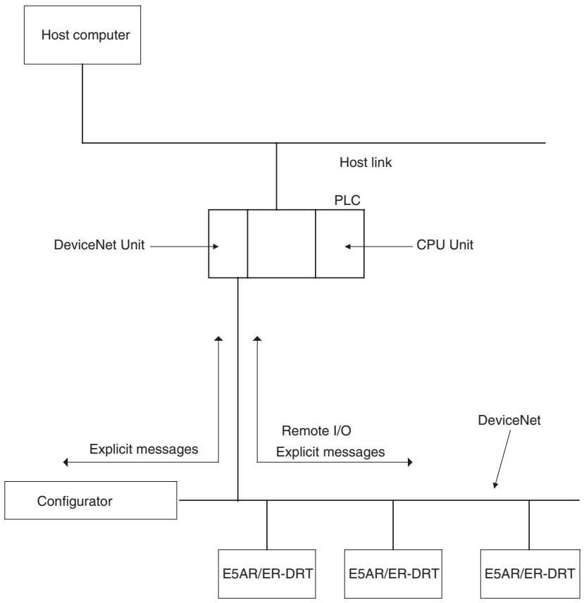
The E5AR/ER-DRT Digital Controllers are slaves that connect to the DeviceNet open field network. DeviceNet communications enable controlling operation, collecting measurement data, and writing settings from a host computer or PLC. The E5AR/ER-DRT support both remote I/O communications and explicit message communications.
Remote I/O communications allow the master and the E5AR/ER-DRT to automatically share data via high-speed I/O without any special programming of the master. Remote I/O communications are particularly suited to operation control, error warnings, and monitoring applications.
Explicit messages use a communications protocol for sending commands and receiving responses. The main application for explicit message communications is for changing E5AR/ER-DRT settings data.
1-1-2 Communications Connection Example
flowchart
graph TD
    A["Host computer"] --> B["PLC"]
    B --> C["DeviceNet Unit"]
    B --> D["CPU Unit"]
    B --> E["DeviceNet"]
    B --> F["DeviceNet"]
    B --> G["DeviceNet"]
    B --> H["DeviceNet"]
    B --> I["DeviceNet"]
    B --> J["DeviceNet"]
    B --> K["DeviceNet"]
    B --> L["DeviceNet"]
    B --> M["DeviceNet"]
    B --> N["DeviceNet"]
    B --> O["DeviceNet"]
    B --> P["DeviceNet"]
    B --> Q["DeviceNet"]
    B --> R["DeviceNet"]
    B --> S["DeviceNet"]
    B --> T["DeviceNet"]
    B --> U["DeviceNet"]
    B --> V["DeviceNet"]
    B --> W["DeviceNet"]
    B --> X["DeviceNet"]
    B --> Y["DeviceNet"]
    B --> Z["DeviceNet"]
    B --> AA["DeviceNet"]
    B --> AB["DeviceNet"]
    B --> AC["DeviceNet"]
    B --> AD["DeviceNet"]
    B --> AE["DeviceNet"]
    B --> AF["DeviceNet"]
    B --> AG["DeviceNet"]
    B --> AH["DeviceNet"]
    B --> AI["DeviceNet"]
    B --> AJ["DeviceNet"]
    B --> AK["DeviceNet"]
    B --> AL["DeviceNet"]
    B --> AM["DeviceNet"]
    B --> AN["DeviceNet"]
    B --> AO["DeviceNet"]
    B --> AP["DeviceNet"]
    B --> AQ["DeviceNet"]
    B --> AR["DeviceNet"]
    B --> AS["DeviceNet"]
    B --> AT["DeviceNet"]
    B --> AU["DeviceNet"]
    B --> AV["DeviceNet"]
    B --> AW["DeviceNet"]
    B --> AX["DeviceNet"]
    B --> AY["DeviceNet"]
    B --> AZ["DeviceNet"]
    B --> BA["DeviceNet"]
    B --> BB["DeviceNet"]
    B --> BC["DeviceNet"]
    B --> BD["DeviceNet"]
    B --> BE["DeviceNet"]
    B --> BF["DeviceNet"]
    B --> BG["DeviceNet"]
    B --> BH["DeviceNet"]
    B --> BI["DeviceNet"]
    B --> BJ["DeviceNet"]
    B --> BK["DeviceNet"]
    B --> BL["DeviceNet"]
    B --> BM["DeviceNet"]
    B --> BN["DeviceNet"]
    B --> BO["DeviceNet"]
    B --> BP["DeviceNet"]
    B --> BQ["DeviceNet"]
    B --> BR["DeviceNet"]
    B --> BS["DeviceNet"]
    B --> BT["DeviceNet"]
    B --> BU["DeviceNet"]
    B --> BV["DeviceNet"]
    B --> BW["DeviceNet"]
    B --> BX["DeviceNet"]
    B --> BY["DeviceNet"]
    B --> BZ["DeviceNet"]
    B --> CA["DeviceNet"]
    B --> CB["DeviceNet"]
    B --> CC["DeviceNet"]
    B --> CD["DeviceNet"]
    B --> CE["DeviceNet"]
    B --> CF["DeviceNet"]
    B --> CG["DeviceNet"]
    B --> CH["DeviceNet"]
    B --> CI["DeviceNet"]
    B --> CJ["DeviceNet"]
    B --> CK["DeviceNet"]
1-1-3 Using DeviceNet
Remote I/O Communications
The master and E5AR/ER-DRT Digital Controllers can share I/O by using remote I/O communications. Data in the E5AR/ER-DRT Digital Controllers, such as process values (PVs) and set points (SPs), can be allocated for communications with the master to enable sending and receiving the allocated data via remote I/O communications without requiring special programming.
Explicit Message Communications
- User-set Data Allocations with a Configurator The specific data required for communications with the master can be allocated by using I/O allocations from the DeviceNet Configurator.
- By sending commands from a PLC, various operations can be performed, including reading/writing specific monitor values and parameters, such as reading process values or writing set points, and performing operations using operation commands. CompoWay/F communications commands can also be executed using explicit message communications.
Automatically Detects Baud Rate
- Previously, the baud rate had to be set for each slave, but the E5AR/ER-DRT Digital Controllers automatically detect and match the baud rate of the master, so this setting is not required. (If the master's baud rate is changed, turn OFF the communications power supply to the Digital Controller and then turn it ON again.)
1-1-4 Default Communications Settings
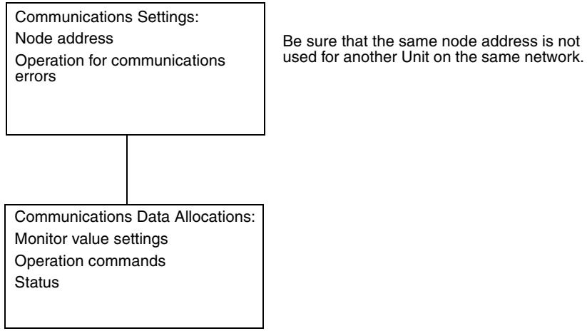
The default settings required for communications when E5AR/ER-DRT are used as DeviceNet slaves are listed in the following diagram.
flowchart
graph TD
    A["Communications Settings: Node address\nOperation for communications errors"] --> B["Communications Data Allocations: Monitor value settings\nOperation commands Status"]
    B --> C["Be sure that the same node address is not used for another Unit on the same network."]
Refer to the DeviceNet Operation Manual (Cat. No. W267) for information such as the order for turning ON power to the master and slaves and master I/O tables.
1-1-5 Data Allocation
E5AR/ER-DRT communications data must be allocated for the IN and OUT Areas for remote I/O communications. Up to 100 words each can be allocated for the IN and OUT Areas. The data for each word is allocated using the parameters communications write data allocations 1 to 100 and communications read data allocations 1 to 100.
Unused words can be specified to reserve space according to data types or to otherwise reduce the number of words.
Refer to 4-2 I/O Allocation on page 4-2 for details on allocation methods.
1-1-6 Remote I/O Communications
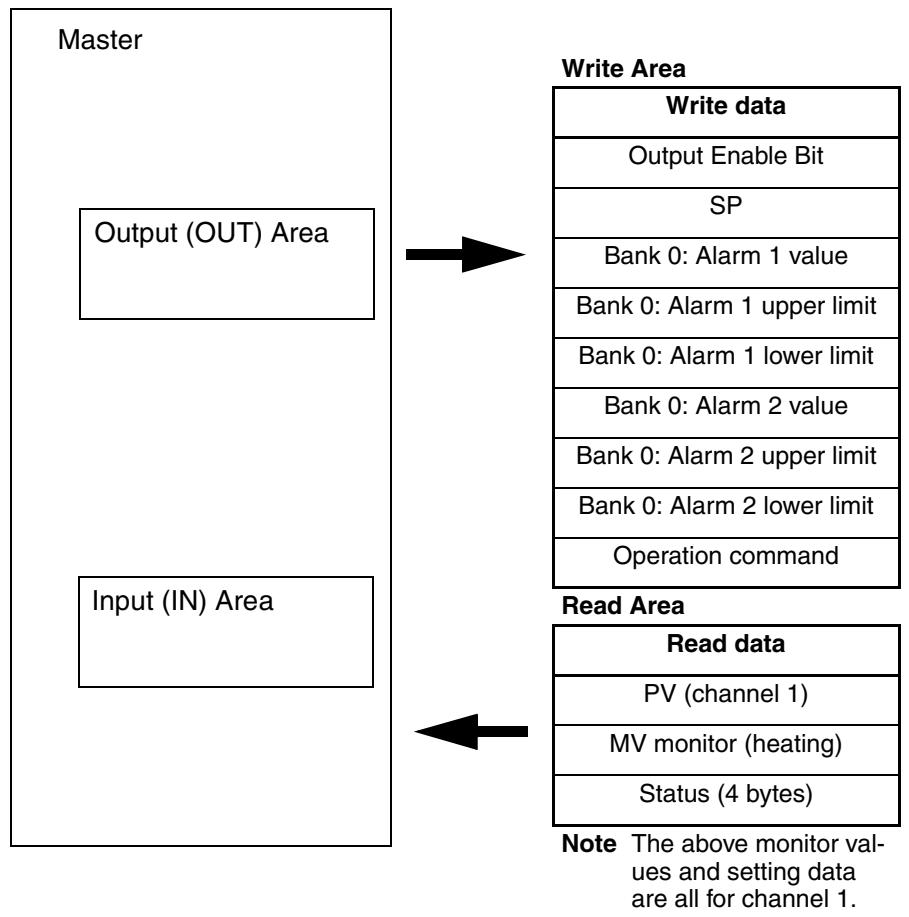
Read/write table data is automatically read and written when communications start. The Communications Write setting must be set to ON to write data from the master to the E5AR/ER-DRT. Data will not be written to the Digital Controller if the Communications Write setting is OFF. The following diagram shows communications with the default data allocation parameters.
Note The Communications Write setting is ON by default.
flowchart
graph TD
    A["Master"] --> B["Input (IN) Area"]
    B --> C["Write Area"]
    C --> D["Write data"]
    C --> E["Output Enable Bit"]
    C --> F["SP"]
    C --> G["Bank 0: Alarm 1 value"]
    C --> H["Bank 0: Alarm 1 upper limit"]
    C --> I["Bank 0: Alarm 1 lower limit"]
    C --> J["Bank 0: Alarm 2 value"]
    C --> K["Bank 0: Alarm 2 upper limit"]
    C --> L["Bank 0: Alarm 2 lower limit"]
    C --> M["Operation command"]
    B --> N["Read Area"]
    N --> O["Read data"]
    O --> P["PV (channel 1)"]
    O --> Q["MV monitor (heating)"]
    O --> R["Status (4 bytes)"]
    style A fill:#f9f,stroke:#333
    style B fill:#f9f,stroke:#333
    style C fill:#ccf,stroke:#333
    style N fill:#cfc,stroke:#333
1-2 Specifications
1-2-1 DeviceNet Communications Specifications
| Item | Specifications | ||||
| Communications protocol | Conforms to DeviceNet | ||||
| Communications functions | Remote I/O communications | Master-slave connections (polling, bit-strobe, COS, or cyclic)Conform to DeviceNet specifications. | |||
| I/O allocations | Can allocate any I/O data from the Configurator.Can allocate any data, such parameters specific to the DeviceNet and the Digital Controller variable area.Up to 2 blocks for the IN Area, up to a total of 100 words (See note 1.)One block for the OUT Area, up to 100 words (The first word is always allocated to Output Enable Bits.) (See note 2.) | ||||
| Message communications | Explicit message communicationsCompoWay/F communications commands can be sent (commands are sent in explicit message format). | ||||
| Connection format | Combination of multidrop and T-branch connections (for trunk and drop lines) | ||||
| Baud rate | DeviceNet: 500, 250, or 125 kbps, or automatic detection of master baud rate | ||||
| Communications media | Special 5-wire cable (2 signal lines, 2 power lines, and 1 shield line) | ||||
| Communications distance | Baud rate | Network length | Drop line length | Total drop line length | |
| 500 kbps | 100 m max. (100 m max.) | 6 m max. | 39 m max. | ||
| 250 kbps | 100 m max. (250 m max.) | 6 m max. | 78 m max. | ||
| 125 kbps | 100 m max. (500 m max.) | 6 m max. | 156 m max. | ||
| The values in parentheses apply when Thick Cables are used. | |||||
| Communications power supply | 11 to 25 VDC | ||||
| Maximum number of nodes that can be connected | 64 (includes Configurator when used) | ||||
| Maximum number of slaves that can be connected | 63 | ||||
| Error control | CRC error detection | ||||
| Power supply | Power supplied from DeviceNet communications connector | ||||
Note
(1) The IN Area can be divided into two blocks only when a CS/CJ-series DeviceNet Unit is used as the master. (The connection type can also be selected.) If a CVM1, CV, or C200HX/HG/HE DeviceNet Master Unit is used as the master, the IN Area must be in 1 block with a maximum 100 words (200 bytes). (Polling connection only.)
(2) If a CVM1, CV, or C200HX/HG/HE DeviceNet Master Unit used, only up to 32 words can be allocated per node.
1-2-2 DeviceNet General Specifications
| Item | Specifications |
| Supply voltage | DeviceNet power supply: 24 VDC (internal circuit) |
| Allowable voltage range | DeviceNet power supply: 11 to 25 VDC |
| Current consumption | DeviceNet power supply: 50 mA max. (24 VDC) |
| Vibration resistance | Vibration: 10 to 55 HzAcceleration: 20 m/s^2 |
| Shock resistance | 150 m/s^2 max. 3 times each in 3 axes, 6 directions |
| Dielectric strength | 2,000 VAC |
| Insulation resistance | 20 MΩ min. (at 500 VDC) |
| Ambient temperature | -10 to 55°C (with no condensation or icing) -10 to 50°C (for 3-year warranty) |
| Ambient humidity | 25% to 85% |
| Storage temperature | -25 to 65°C (with no condensation or icing) |
| Enclosure rating | IP00 (connector) |
| Memory protection | EEPROM (100,000 write operations) |
| Weight | Connector cover: Approx. 2 g DeviceNet connector: Approx. 10 g |
SECTION 2
Operating Procedures
This section outlines the basic operating procedures for the E5AR/ER-DRT Digital Controllers.
2-1 Introduction.... 2-2
2-1-1 Setup Procedure 2-2
2-1-2 Startup Procedure 2-2
2-1-3 Setting Node Addresses 2-3
2-2 Functions Supported Only by the E5AR/ER-DRT 2-4
2-2-1 Network Power Monitor Function 2-4
2-2-2 Accumulated ON (RUN) Time Monitor Function 2-5
2-2-3 Operation for Communications Errors 2-5
2-1 Introduction
Use the procedures in the following sections to prepare the E5AR/ER-DRT Digital Controllers for use. Refer to the following reference pages/sections provided for detailed information on each step.
2-1-1 Setup Procedure
| Step | Item | Details | Reference |
| 1 | Mount the Digital Controller. | Mount the Digital Controller to the panel. | page 3-4 |
| 2 | Wire the Digital Controller. | Wire the temperature inputs and control outputs to the Digital Controller terminals.Note Do not turn ON the power supply to the peripheral devices at this time. | page 3-10 |
| 3 | Turn ON the power to the Digital Controller. | Turn ON the power connected to the Digital Controller.Note The Digital Controller will start. | page 3-10 |
| 4 | Set the DeviceNet node address. | Set the DeviceNet node address (0 to 63) for the Digital Controller on the front panel. Set a unique node address for each slave connected to the same master. | page 2-3 |
| 5 | Turn OFF the power to the Digital Controller. | Turn OFF the power connected to the Digital Controller. | --- |
2-1-2 Startup Procedure
Prepare the master, DeviceNet communications power supply, and Configurator that will be used in the system. Use the Configurator to allocate Digital Controller data in the IN and OUT Areas. Refer to the DeviceNet Operation Manual (W267) for information on related connection devices.
Note Up to 100 words each can be allocated in the IN Area and OUT Area for remote I/O communications. To read and write larger amounts of data, use explicit messages. Use explicit message communications also for reading and writing data only when required.
| Step | Item | Details | Reference |
| 6 | Connect the DeviceNet communications connector. | Connect the DeviceNet communications connector.Note Do not turn ON the communications power supply at this time. This power supply is also used as the internal circuit power supply for DeviceNet communications. | page 3-15 |
| 7 | Turn ON the power to the Digital Controller. | Turn ON the power connected to the Digital Controller.Note The Digital Controller will start. | page 3-10 |
| 8 | Turn ON the DeviceNet communications power (V+, V−). | Turn ON the communications power supply to DeviceNet.Note The DeviceNet communications will start. | --- |
| 9 | Check the MS/NS indicators | Check that the status of the MS and NS indicators is as follows:MS: Operating normally when lit green.NS: Operating normally when lit green.(DeviceNet online or communications connected.) | page 3-3 |
| 10 | Operate from the Configurator. | Set from the Configurator when changing data allocated in the IN and OUT Areas from the default values.To split the IN Area used by the E5AR/ER-DRT into two areas, select E5AR/ER-DRT in the master's Edit Device Parameters Window and set the connection in the detailed settings.When the IN Area is split into two areas, for example, operating parameters, such as set points and process values, can be allocated in IN Area 1, and status values can be allocated in IN Area 2. For example, IN Area 1 can be allocated in the DM Area and IN Area 2 can be allocated in the CIO Area. | SECTION 4Remote I/O Communications |
| 11 | Start remote I/O communications. | Enable the master's scan list and change the PLC to RUN Mode.Remote I/O communications will start, and the contents of the IN and OUT Areas in the master and E5AR/ER-DRT Digital Controller will be synchronized. | --- |
| 12 | Use explicit message communications. | Send explicit messages from the master.Explicit messages can be used to perform control and monitoring that cannot be achieved using the IN and OUT Areas alone, by sending explicit messages to the E5AR/ER-DRT Digital Controller. | SECTION 5Explicit Message Communications |
Observe the following precautions when editing device parameters using the Configurator.
- It is recommended that device default values are uploaded before the parameters are edited because the EDS parameter defaults and the device defaults are different.
- If “Unit No.” (communications unit number) is displayed in the Communications Setting parameter group, set the “Unit No.” to the node address.
- If "Input 2 Type" is displayed in the Input Initial Setting parameter group for the E5AR-□□□B-DRT, E5ER-□□□B-DRT, E5AR-□□□F-DRT, or E5ER-□□□F-DRT, set the "Input 2 Type" to 15. The default value may not be downloaded.
- Related settings are not initialized when data is downloaded from the Configurator. Refer to the Appendix in the E5AR/E5ER Digital Controller User's Manual (Cat. No. H124) for information on how to correctly set related data.
- The automatic selection range upper limit (DV) can be set from the front panel or it can be set using the automatic selection range upper limit (PV) parameter (PID*AUT(PV)). When using the automatic selection range upper limit (PV) parameter, set the value obtained from the following equation:
Automatic selection range upper limit (PV) = Automatic selection range upper limit (DV) + Sensor setting range lower limit
2-1-3 Setting Node Addresses
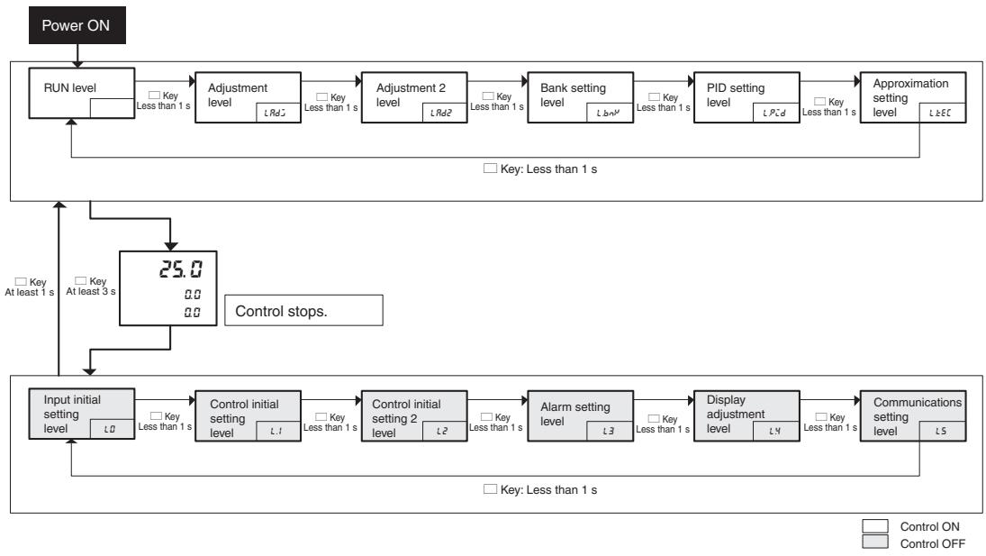
DeviceNet node addresses are set in the communications setting level. Set the node addresses on the front panel of the E5AR/ER-DRT.
- The node address will be 0 if an address between 64 and 99 is set.
Setting Operation
flowchart
graph TD
    A["Power ON"] --> B["RUN level"]
    B --> C["Adjustment level"]
    C --> D["Adjustment 2 level"]
    D --> E["Bank setting level"]
    E --> F["PID setting level"]
    F --> G["Approximation setting level"]
    G --> H["Control stops."]
    H --> I["25.0"]
    I --> J["Control initial setting level"]
    J --> K["Control initial setting level"]
    K --> L["Control initial setting 2 level"]
    L --> M["Alarm setting level"]
    M --> N["Display adjustment level"]
    N --> O["Communications setting level"]
    O --> P["Control ON"]
    style A fill:#f9f,stroke:#333
    style B fill:#ccf,stroke:#333
    style C fill:#cfc,stroke:#333
    style D fill:#cfc,stroke:#333
    style E fill:#cfc,stroke:#333
    style F fill:#cfc,stroke:#333
    style G fill:#cfc,stroke:#333
    style H fill:#fcc,stroke:#333
    style I fill:#cff,stroke:#333
    style J fill:#ffc,stroke:#333
    style K fill:#ffc,stroke:#333
    style L fill:#ffc,stroke:#333
    style M fill:#ffc,stroke:#333
    style N fill:#ffc,stroke:#333
    style O fill:#ffc,stroke:#333
    style P fill:#ffc,stroke:#333
Setting Parameters
Press the LEVEL Key for at least 3 s to move from the RUN level to the input initial setting level.
Press the LEVEL Key several times to move from the input initial setting level to the communications setting level.
The communications unit number ( -n ) (DeviceNet node address) will be displayed.
Press the UP and DOWN Keys to change the setting.
The number of words allocated will depend on the E5AR/ER-DRT communications data allocations. The following points are important when setting node addresses or allocating I/O memory.
- Do not allocate the same words to other slaves.
- Make sure the I/O area does not exceed the valid range.
2-2 Functions Supported Only by the E5AR/ER-DRT
A Configurator is used to make settings for the network power monitor function, accumulated ON (RUN) time monitor function, and control at error function.
2-2-1 Network Power Monitor Function
The E5AR/ER-DRT has a network power monitor function that turns ON the Communications Power Voltage Monitor Error Flag in the General Status when the communications power voltage drops below the set monitor value. The monitor value for the network power voltage is set using the Configurator and is found in the General Setting parameter group.
2-2-2 Accumulated ON (RUN) Time Monitor Function
The E5AR/ER-DRT has accumulated ON (RUN) time monitor functions which record internally the total time communications power is supplied or the accumulated RUN (control) time. The Unit Maintenance Flag in the General Status will turn ON if the accumulated time exceeds a set monitor value.
The Detection Mode and Detection Time are set using a Configurator and are found in the General Setting parameter group.
The ON (RUN) time monitor function can be used as a guide for replacing the E5AR/ER-DRT Digital Controller.
Measurement unit: 0.1 h
Measurement range: 0 to 429496729.5 h (Stored data: 00000000 to FFFFFFFF hex).
Note
(1) The ON or RUN time is held even when the power is turned OFF.
(2) Both the ON and RUN time monitor functions cannot be used at the same time for one word.
(3) The accumulated time will not be measured if communications power is not supplied to the E5AR/ER-DRT.
(4) The E5AR/ER-DRT Digital Controller checks the ON/RUN status of the target channel approximately every 0.1 h (6 min.).
2-2-3 Operation for Communications Errors
The “Control at Error” specifies the operation to be performed if a DeviceNet communications error occurs. The Control at Error setting is made using the Configurator and is found in the Communications Setting parameter group.
| Setting range | Unit | Default |
| ContinueStop | --- | Continue |
SECTION 3
Parts, Installation, and Wiring
This section describes the methods used to install and wire E5AR/E5ER-DRT Digital Controllers.
3-1 Part Names and Functions.... 3-2
3-1-1 Part Names 3-2
3-1-2 External Dimensions.... 3-2
3-1-3 MS and NS Indicators.... 3-3
3-1-4 Installation 3-4
3-2 How to Use the Terminals.... 3-6
3-2-1 Connections 3-6
3-2-2 Precautions when Wiring 3-9
3-2-3 Wiring.... 3-10
3-3 DeviceNet Communications Cables Wiring 3-15
3-3-1 Preparing DeviceNet Communications Cables. 3-15
3-3-2 Attaching the DeviceNet Communications Unit Connector..... 3-16
3-3-3 Insulation Blocks 3-18
3-1 Part Names and Functions
3-1-1 Part Names
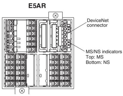
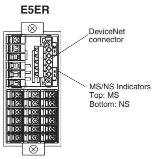
DeviceNet Communications Connector
The DeviceNet communications connector is used to connect the communications cable to the DeviceNet network. The DeviceNet communications power is also supplied through this connector. The connector provided with the Controller is the FKC 2.5/5-STF-5.08 AU M (Phoenix Contact).
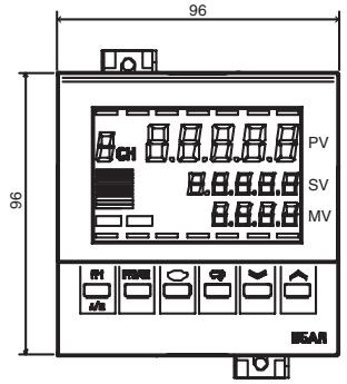
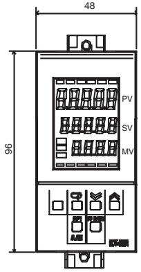
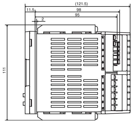
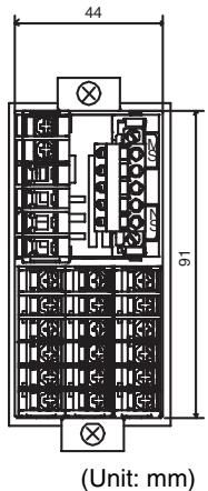
3-1-2 External Dimensions
E5AR
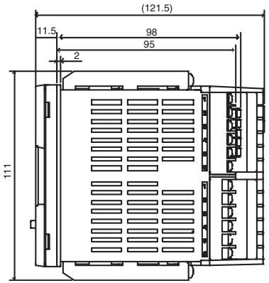
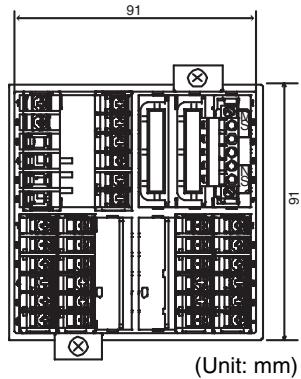
E5ER
3-1-3 MS and NS Indicators
The indicators show the status of the Digital Controller and the DeviceNet Network.
| Indicator | Name | Color | Status | Meaning (main errors) |
| MS | Module status | Green |  | The Controller is normal. |
| Red |  | Fatal errorController errorWatchdog timer error (DeviceNet communications) | ||
 | Non-fatal errorUnit errorUnit changedDisplay Unit errorNon-volatile memory error | |||
| OFF |  | No power is being supplied.DeviceNet communications power is not being supplied.Power is not being supplied to the Controller.The Controller is being reset.Waiting for initialization to start. | ||
| NS | Network status | Green |  | Online/communications established (normal network status) |
 | Online/communications not established (waiting for connection to be established with the master) | |||
| Red |   | Fatal communications error (The Controller has detected an error that does not allow communications with the network.)Node address duplication errorBus OFF error detected | ||
| NS/T233 | Non-fatal communications errorCommunications timeout | |||
| OFF |  | Offline or power supply is OFFWaiting for completion of the master's node address duplication check.DeviceNet communications power is not being supplied. |
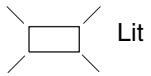

Flashing

Not lit
Normal Indicator Display
The MS and NS indicators are both lit green when the status of the Controller and the Network are normal.
3-1-4 Installation
Panel Cutout Dimensions
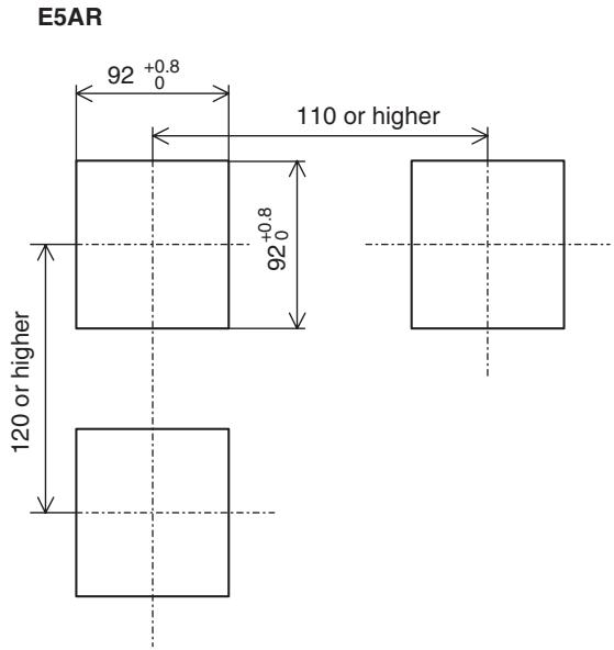
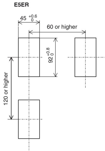
Installation Procedure
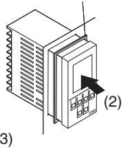
- If the front of the Controller needs to be watertight, attach the provided watertight packing.
If the front of the Controller does not need to be watertight, the watertight packing does not need to be attached.
- Insert the Controller into the cutout in the panel.
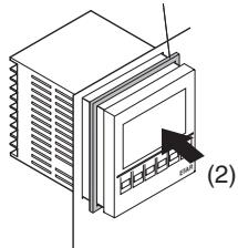
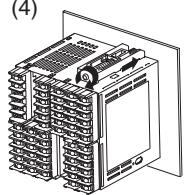
- Insert the accompanying fittings into the grooves on the top and bottom of the rear case.
- Gradually tighten the screws in the top and bottom fittings, alternating between each so that they are balanced. Tighten until the ratchet turns without engaging.
E5AR
(1) Watertight packing (Model Y92S-P4)
natural_image
Diagram of a server rack with a monitor and indicator lights, labeled (2), showing no text or symbols beyond the label.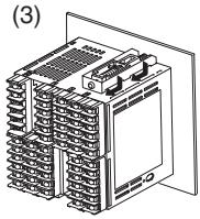
(4)
E5ER
(1) Watertight packing (Model Y92S-P5)
natural_image
Isometric illustration of a device with a labeled component (2), no text or symbols present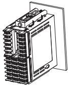
(4)
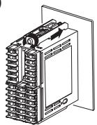
Pulling Out the Controller
Normally there is no need to pull out the Controller, however, it can be pulled out if needed for maintenance.
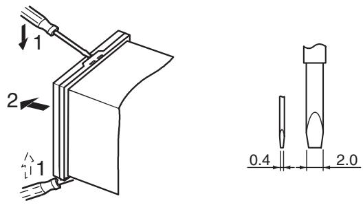
When pulling out the Controller, place a cloth over the screwdriver to prevent scratches and other damage.
Note Remove the DeviceNet connector before drawing out the Controller.
3-2 How to Use the Terminals
Verify the layout of the terminals (A on and 1 on) using the engravings on the top and sides of the case.
3-2-1 Connections
E5AR
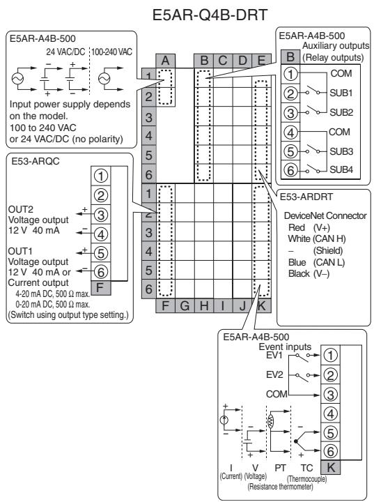
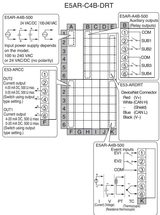
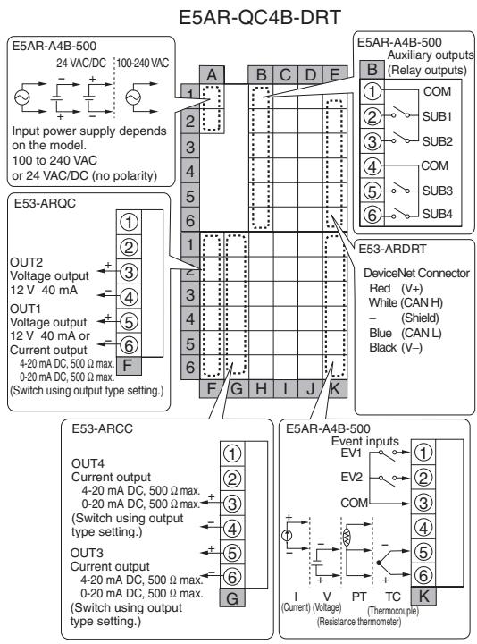
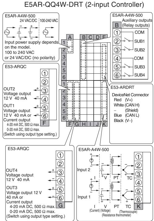
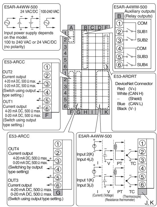
E5AR-CC4WW-DRT (4-input Controller)
E5AR-PR4F-DRT
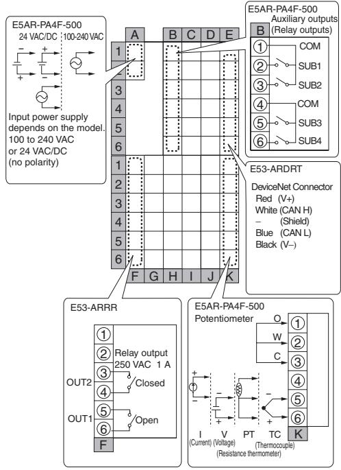
E5AR-PRQ4F-DRT

flowchart
graph TD
    subgraph Input Power Supply
        A["Input power supply depends on the model.<br>100 to 240 VAC<br>or 24 VAC/DC (no polarity)"]
    end

    subgraph Auxiliary Outputs
        B["Auxiliary outputs<br>(Relay outputs)"]
        C["DeviceNet Connector<br>Red (V+)<br>White (CAN H) - (Shield)<br>Blue (CAN L) Black (V-)"]
    end

    subgraph Device Network
        D["DeviceNet Connector<br>Red (V+)<br>White (CAN H) - (Shield)<br>Blue (CAN L) Black (V-)"]
    end

    subgraph Potentiometer
        E["Thermocouple"]
        F["Current (Voltage)"]
        G["Resistance thermometer"]
    end

    A -->|A 1| B
    A -->|B 2| C
    A -->|C 3| D
    A -->|D 4| E
    A -->|E 5| F
    A -->|E 6| G
    A -->|E 7| H
    A -->|E 8| I
    A -->|E 9| J
    A -->|E 10| K
    A -->|E 11| L
    A -->|E 12| M
    A -->|E 13| N
    A -->|E 14| O
    A -->|E 15| P
    A -->|E 16| Q
    A -->|E 17| R
    A -->|E 18| S
    A -->|E 19| T
    A -->|E 20| U
    A -->|E 21| V
    A -->|E 22| W
    A -->|E 23| X
    A -->|E 24| Y
    A -->|E 25| Z
    A -->|E 26| AA
    A -->|E 27| AB
    A -->|E 28| AC
    A -->|E 29| AD
    A -->|E 30| AE
    A -->|E 31| AF
    A -->|E 32| AG
    A -->|E 33| AH
    A -->|E 34| AI
    A -->|E 35| AJ
    A -->|E 36| AK
    A -->|E 37| AL
    A -->|E 38| AM
    A -->|E 39| AN
    A -->|E 40| AO
    A -->|E 41| AP
    A -->|E 42| AQ
    A -->|E 43| AR
    A -->|E 44| AS
    A -->|E 45| AT
    A -->|E 46| AU
    A -->|E 47| AV
    A -->|E 48| AW
    A -->|E 49| AX
    A -->|E 50| AY
    A -->|E 51| AZ
    A -->|E 52| BA
    A -->|E 53| BB
    A -->|E 54| BC
    A -->|E 55| BD
    A -->|E 56| BE
    A -->|E 57| BF
    A -->|E 58| BG
    A -->|E 59| BH
    A -->|E 60| BI
    A -->|E 61| BJ
    A -->|E 62| BK
    A -->|E 63| BL
    A -->|E 64| BM
    A -->|E 65| BN
    A -->|E 66| BO
    A -->|E 67| BP
    A -->|E 68| BQ
    A -->|E 69| BR
    A -->|E 70| BS
    A -->|E 71| BT
    A -->|E 72| BU
    A -->|E 73| BV
    A -->|E 74| BW
    A -->|E 75|
    A -->|E 76|
    A -->|E 77|
    A -->|E 78|
    A -->|E 79|
    A -->|E 80|
    A -->|E 81|
    A -->|E 82|
    A -->|E 83|
    A -->|E 84|
    A -->|E 85|
    A -->|E 86|
    A -->|E 87|
    A -->|E 88|
    A -->|E 89|
    A -->|E 90|
    A -->|E 91|
    A -->|E 92|
    A -->|E 93|
    A -->|E 94|
    A -->|E 95|
    A -->|E 96|
    A -->|E 97|
    A -->|E 98|
    A -->|E 99|
    B --> C
    C --> D
    D --> E
    E --> F
    F --> G
    G --> H
    H --> I
    I --> J
    J --> K
    K --> L

    style Input Power Supply fill:#f9f,stroke:#333,stroke-width:2px
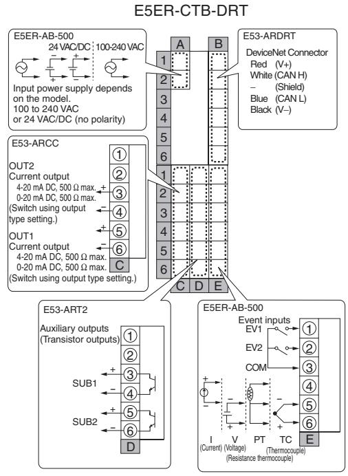
E5ER
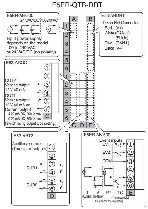
flowchart
graph TD
    subgraph E5ER-QTB-DRT
        A["Input power supply depends on the model.<br>100 to 240 VAC or 24 VAC/DC (no polarity)"]
        B["E53-ARDRT DeviceNet Connector<br>Red (V+)<br>White (CAN H) - (Shield)<br>Blue (CAN L) Black (V-)"]
        C["E53-ART2 Auxiliary outputs<br>(Transistor outputs)"]
        D["E5ER-AB-500 Event inputs<br>EV1 EV2 COM I V PT TC E"]
    end
    subgraph E53-ARQC
        E["OUT2 Voltage output<br>12 V 40 mA OUT1 Voltage output<br>12 V 40 mA or Current output<br>4-20 mA DC, 500 Ω max.<br>0-20 mA DC, 500 Ω max.<br>(Switch using output type setting.)"]
        F["SUB1"]
        G["SUB2"]
        H["D"]
    end
    subgraph E53-ARDRT
        I["1"]
    end
    subgraph E5ER-AB-500
        J["1"]
        K["2"]
        L["3"]
        M["4"]
        N["5"]
        O["6"]
        P["7"]
        Q["8"]
        R["9"]
        S["10"]
        T["11"]
        U["12"]
        V["13"]
        W["14"]
        X["15"]
        Y["16"]
        Z["17"]
        AA["18"]
        AB["19"]
        AC["20"]
        AD["21"]
        AE["22"]
        AF["23"]
        AG["24"]
        AH["25"]
        AI["26"]
        AJ["27"]
        AK["28"]
        AL["29"]
        AM["30"]
        AN["31"]
        AO["32"]
        AP["33"]
        AQ["34"]
        AR["35"]
        AS["36"]
        AT["37"]
        AU["38"]
        AV["39"]
        AW["40"]
        AX["41"]
        AY["42"]
        AZ["43"]
        BA["44"]
        BB["45"]
        BC["46"]
        BD["47"]
        BE["48"]
        BF["49"]
        BG["50"]
        BH["51"]
        BI["52"]
        BJ["53"]
        BK["54"]
        BL["55"]
        BM["56"]
        BN["57"]
        BO["58"]
        BP["59"]
        BQ["60"]
    end
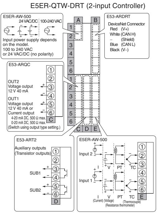
flowchart
graph TD
    subgraph_E5ER-QTW-DRT["2-input Controller"]
        A1["E53-ARDRT DeviceNet Connector Red (V+)"]
        A2["White (CAN H)"]
        A3["Blue (CAN L)"]
        A4["Black (V-)"]
    end

    subgraph_E53-ART2["Auxiliary outputs (Transistor outputs)"]
        B1["E5ER-AW-500 Input 2"]
        B2["E5ER-AW-500 Current I (Current) (Voltage) (Thermocouple)"]
        B3["E5ER-AW-500 Sub1"]
        B4["E5ER-AW-500 Sub2"]
    end

    subgraph_E53-ARQC["4-20 mA DC, 500 Ω max."]
        C1["OUT2 Voltage output 12 V 40 mA"]
        C2["OUT1 Voltage output 12 V 40 mA or Current output 4-20 mA DC"]
        C3["OUT2 OUT2 Voltage output 12 V 40 mA"]
        C4["OUT1 OUT1 Voltage output 12 V 40 mA or Current output 4-20 mA DC"]
        C5["OUT2 OUT2 Voltage output 12 V 40 mA or Current output 4-20 mA DC"]
        C6["OUT1 OUT1 Voltage output 12 V 40 mA or Current output 4-20 mA DC"]
        C7["OUT2 OUT2 Voltage output 12 V 40 mA or Current output 4-20 mA DC"]
        C8["OUT1 OUT1 Voltage output 12 V 40 mA or Current output 4-20 mA DC"]
        C9["OUT2 OUT2 Voltage output 12 V 40 mA or Current output 4-20 mA DC"]
        D["Switch using output type setting."]
    end

    subgraph_E5ER-AW-500["DeviceNet Connector Red (V+)"]
        E1["E5ER-AW-500 Input 2"]
        E2["E5ER-AW-500 Current I (Current) (Voltage) (Thermocouple)"]
        E3["E5ER-AW-500 Sub1"]
        E4["E5ER-AW-500 Sub2"]
    end
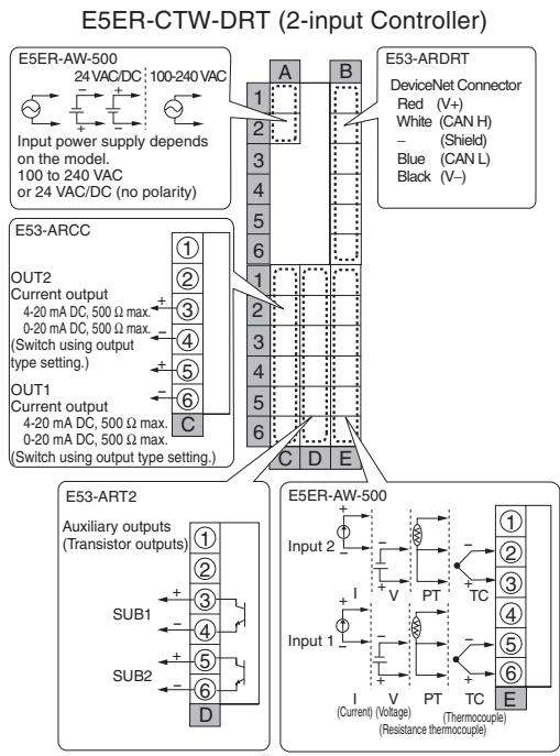
3-2-2 Precautions when Wiring
- To avoid the effects of noise, wire the signal wires and power lines separately.
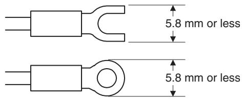
- Use crimp terminals to connect to the terminals.
- Tighten screws to the following torques
Terminal block screws: 0.40 to 0.56 N·m
Connector screws: 0.25 to 0.30 N·m - The crimp terminals must be M3 and either of the following shapes.
3-2-3 Wiring
Power Supply (Terminals)
The inside of the frames around terminal numbers in the wiring diagrams indicate the interior of the Controller, and the outside of the frame indicates the exterior.
- Connect terminals A1 to A2 as follows:
E5AR
| A | B | C | D | E | |||
| 1 | 1 | ||||||
| 2 | 2 | ||||||
| 3 | 3 | ||||||
| 4 | 4 | ||||||
| 5 | 5 | ||||||
| 6 | 6 | ||||||
| 1 | 1 | ||||||
| 2 | 2 | ||||||
| 3 | 3 | ||||||
| 4 | 4 | ||||||
| 5 | 5 | ||||||
| 6 | 6 | ||||||
| F | G | H | I | J | K |
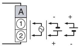
The input power supply depends on the model. 100 to 240 VAC, or 24 VAC/VDC (no polarity)
E5ER
| A | B | |||
| 1 | 1 | |||
| 2 | 2 | |||
| 3 | 3 | |||
| 4 | 4 | |||
| 5 | 5 | |||
| 6 | 6 | |||
| 1 | 1 | |||
| 2 | 2 | |||
| 3 | 3 | |||
| 4 | 4 | |||
| 5 | 5 | |||
| 6 | 6 | |||
| C | D | E |
| Input voltage | E5AR | E5ER |
| 100 to 240 VAC 50/60Hz | 22 VA | 17 VA |
| 24 VAC 50/60Hz | 15 VA | 11 VA |
| 24 VDC (no polarity) | 10 W | 7 W |
Inputs (Terminals)
E5AR
| A | B | C | D | E | |||
| 1 | 1 | ||||||
| 2 | 2 | ||||||
| 3 | 3 | ||||||
| 4 | 4 | ||||||
| 5 | 5 | ||||||
| 6 | 6 | ||||||
| 1 | IN4 | IN2 | 1 | ||||
| 2 | 2 | ||||||
| 3 | 3 | ||||||
| 4 | IN3 | IN1 | 4 | ||||
| 5 | 5 | ||||||
| 6 | 6 | ||||||
| F | G | H | I | J | K |
- For Input 1 (IN1), connect terminals K4 to K6 on the E5AR, or E4 to E6 on the E5ER, as shown below according to the input type.
- For a multi-point input type, connect inputs 2 to 4 (IN2 to IN4) in the same way according to the number of input points.
E5AR

E5ER
| A | B | |||
| 1 | 1 | |||
| 2 | 2 | |||
| 3 | 3 | |||
| 4 | 4 | |||
| 5 | 5 | |||
| 6 | 6 | |||
| 1 | IN2 | 1 | ||
| 2 | 2 | |||
| 3 | 3 | |||
| 4 | IN1 | 4 | ||
| 5 | 5 | |||
| 6 | 6 | |||
| C | D | E |
E5ER
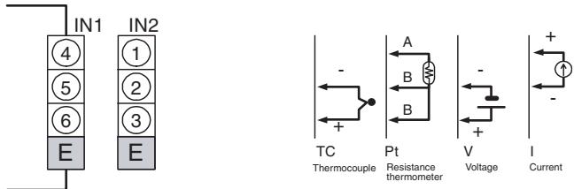
To prevent the appearance of error displays due to unused inputs, set the number of enabled channels.
Control Outputs or Transfer Outputs (Terminals)
E5AR
| A | B | C | D | E | |||
| 1 | 1 | ||||||
| 2 | 2 | ||||||
| 3 | 3 | ||||||
| 4 | 4 | ||||||
| 5 | 5 | ||||||
| 6 | 6 | ||||||
| 1 | 1 | ||||||
| 2 | 2 | ||||||
| 3 | OUT2 | OUT4 | 3 | ||||
| 4 | 4 | ||||||
| 5 | OUT1 | OUT3 | 5 | ||||
| 6 | 6 | ||||||
| F | G | H | I | J | K |
E5ER
| A | B | |||
| 1 | 1 | |||
| 2 | 2 | |||
| 3 | 3 | |||
| 4 | 4 | |||
| 5 | 5 | |||
| 6 | 6 | |||
| 1 | 1 | |||
| 2 | 2 | |||
| 3 | OUT2 | OUT4 | 3 | |
| 4 | 4 | |||
| 5 | OUT1 | OUT3 | 5 | |
| 6 | 6 | |||
| C | D | E |
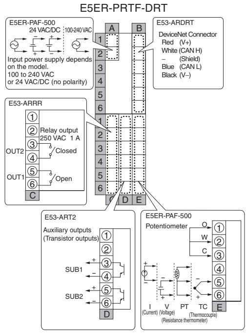
- On the E5AR, control output 1 (OUT1) outputs to terminals F5 and F6, and control output 2 (OUT2) outputs to terminals F3 and F4.
- On the E5ER, control output 1 (OUT1) outputs to terminals C5 and C6, and control output 2 (OUT2) outputs to terminals C3 and C4.
- On a multi-point input type, output takes place from control output 3 (OUT3) and control output 4 (OUT4).
E5AR
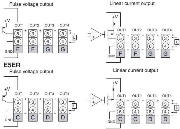
- If terminals 5 and 6 are used for pulse voltage output, approximately 2 V are output when the power is turned ON. (Load resistance: 10 kΩ or less for 10 ms)
- For linear current output, approximately 2 mA are output for 1 ms when the power is turned ON.
- Control outputs that are not used for control can be used for transfer output with the “control output/transfer output assignment” setting.
- Specifications for each output type are listed in the following table.
| Output type | Specifications |
| Pulse voltage output | Output voltage: 12 VDC+15%, -20% (PNP)Maximum load current: 40 mA, with short-circuit protection circuit |
| Linear current output | 0 to 20 mA DC (resolution: approx. 54,000)4 to 20 mA DC (resolution: approx. 43,000)Load: 500 Ω or less |
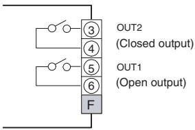
- The Position-proportional Models have relay outputs (250 VAC, 1 A). Control output 1 (OUT1) is open output and control output 2 (OUT2) is closed output.
E5AR
E5ER
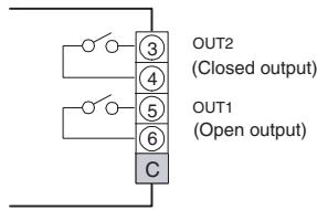
- Relay output specifications are as follows: 250 VAC, 1 A (including inrush current)
Auxiliary Outputs (Terminals)
E5AR
| A | B | C | D | E | |||
| 1 | COM | 1 | |||||
| 2 | SUB1 | 2 | |||||
| 3 | SUB2 | 3 | |||||
| 4 | COM | 4 | |||||
| 5 | SUB3 | 5 | |||||
| 6 | SUB4 | 6 | |||||
| 1 | 1 | ||||||
| 2 | 2 | ||||||
| 3 | 3 | ||||||
| 4 | 4 | ||||||
| 5 | 5 | ||||||
| 6 | 6 | ||||||
| F | G | H | I | J | K |
E5ER
| A | B | |||
| 1 | 1 | |||
| 2 | 2 | |||
| 3 | 3 | |||
| 4 | 4 | |||
| 5 | 5 | |||
| 6 | 6 | |||
| 1 | 1 | |||
| 2 | 2 | |||
| 3 | SUB1 | 3 | ||
| 4 | 4 | |||
| 5 | SUB2 | 5 | ||
| 6 | 6 | |||
| C | D | E |
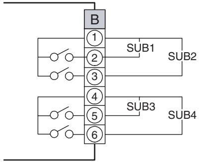
- On the E5AR-□4□□, auxiliary outputs 1 to 4 (SUB1 to 4) output to terminals B1 to B6.
- Relay output specifications are as follows: 250 VAC 1 A
E5AR
flowchart
graph TD
    A["Component B"] --> B1["1"]
    A --> B2["2"]
    A --> B3["3"]
    A --> B4["4"]
    A --> B5["5"]
    A --> B6["6"]
    B1 --> C1["SUB1"]
    B2 --> C2["SUB2"]
    B3 --> C3["SUB3"]
    B4 --> C4["SUB4"]
- On the E5ER-□T□□ auxiliary outputs 1 and 2 (SUB1 and 2) output to terminals D3 to D6.
E5ER
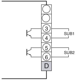
- Transistor output specifications are as follows:
Max. Load voltage: 30 VDC
Max. Load current: 50 mA
Residual voltage: 1.5 V
Leakage current: 0.4 mA
Potentiometer Inputs (Terminals)
E5AR
| A | B | C | D | E | |||
| 1 | 1 | ||||||
| 2 | 2 | ||||||
| 3 | 3 | ||||||
| 4 | 4 | ||||||
| 5 | 5 | ||||||
| 6 | 6 | ||||||
| 1 | PMTR | 1 | |||||
| 2 | 2 | ||||||
| 3 | 3 | ||||||
| 4 | 4 | ||||||
| 5 | 5 | ||||||
| 6 | 6 | ||||||
| F | G | H | I | J | K |
E5ER
| A | B | |||
| 1 | 1 | |||
| 2 | 2 | |||
| 3 | 3 | |||
| 4 | 4 | |||
| 5 | 5 | |||
| 6 | 6 | |||
| 1 | PMTR | 1 | ||
| 2 | 2 | |||
| 3 | 3 | |||
| 4 | 4 | |||
| 5 | 5 | |||
| 6 | 6 | |||
| C | D | E |
- If you want to use a Controller with position-proportional control to monitor the amount of valve opening or perform closed control, connect a potentiometer (PMTR) as shown below.
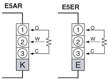
- For information on the potentiometer, see the manual for the valve you are connecting. Terminal number meanings are as follows:
O: OPEN, W: WIPE, C: CLOSE
The input range is 100 Ω to 2.5 kΩ (between C and O).
Event Inputs (Terminals)
E5AR
| A | B | C | D | E | |||
| 1 | 1 | ||||||
| 2 | 2 | ||||||
| 3 | 3 | ||||||
| 4 | 4 | ||||||
| 5 | 5 | ||||||
| 6 | 6 | ||||||
| 1 | EV1 | 1 | |||||
| 2 | EV2 | 2 | |||||
| 3 | COM | 3 | |||||
| 4 | 4 | ||||||
| 5 | 5 | ||||||
| 6 | 6 | ||||||
| F | G | H | I | J | K |
E5ER
| A | B | |||
| 1 | 1 | |||
| 2 | 2 | |||
| 3 | 3 | |||
| 4 | 4 | |||
| 5 | 5 | |||
| 6 | 6 | |||
| 1 | EV1 | 1 | ||
| 2 | EV2 | 2 | ||
| 3 | COM | 3 | ||
| 4 | 4 | |||
| 5 | 5 | |||
| 6 | 6 | |||
| C | D | E |
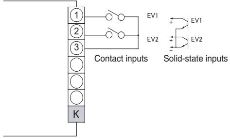
- To use the event inputs with the E5AR, connect event inputs 1 and 2 (EV1 and EV2) to terminals K1 to K3 as shown below.
- To use the event inputs with the E5ER, connect event inputs 1 and 2 (EV1 and EV2) to terminals E1 to E3 as shown below.
E5AR
E5ER
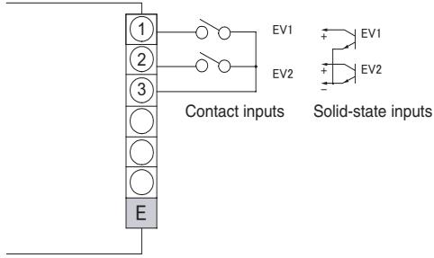
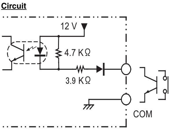
- The ratings for event inputs are given in the following table.
| Contact inputs | ON: 1 KΩ max., OFF: 100 KΩ min. |
| Solid-state inputs | ON residual voltage: 1.5 V or lessOFF leakage current: 0.1 mA or less |
3-3 DeviceNet Communications Cables Wiring
The methods used for preparing DeviceNet communications cables to be connected for DeviceNet communications are explained here.
For details on the DeviceNet Network, such as supplying the DeviceNet communications power and grounding the DeviceNet Network, refer to the DeviceNet Operation Manual (W267). The wiring methods for Thin Cable are described in this section.
3-3-1 Preparing DeviceNet Communications Cables
Use the following procedure to prepare and connect the communications cables to the connectors.
1,2,3...
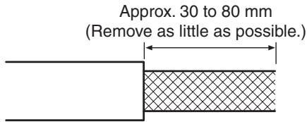
- Remove approximately 30 to 80 mm of the cable covering, being careful not to damage the shield mesh underneath. Do not remove too much covering or a short circuit may result.
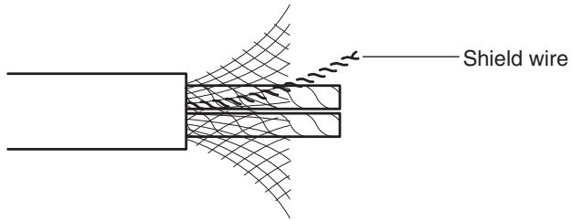
- Carefully peel back the shield mesh to reveal the signal lines, power lines, and the shield wire. The shield wire is slightly harder to the touch than the mesh.
- Remove the exposed mesh and the aluminum tape from the signal and power lines. Strip the covering from the signal and power lines to the proper length for the crimp terminals. Twist together the wires of each of the signal and power lines.

natural_image
Cross-sectional diagram of a cable with multiple insulation sheaths (no text or labels)Strip to match the crimp terminals.
- Attach crimp terminals to the lines and then cover any exposed areas with vinyl tape or heat-shrink tubing.
Orient the connector properly, then insert each of the signal lines, power supply lines, and the shield wire into the connector holes from the top in the order red, white, shield, blue, black, as shown in the following diagram. The DeviceNet-compatible Controllers are equipped with screwless connectors, so the cables do not need to be secured with screws as with previous DeviceNet communications connectors. With the orange lever pushed down, insert each of the lines into the back of the holes.
Release the orange lever and gently tug on each line to check that it is connected properly.
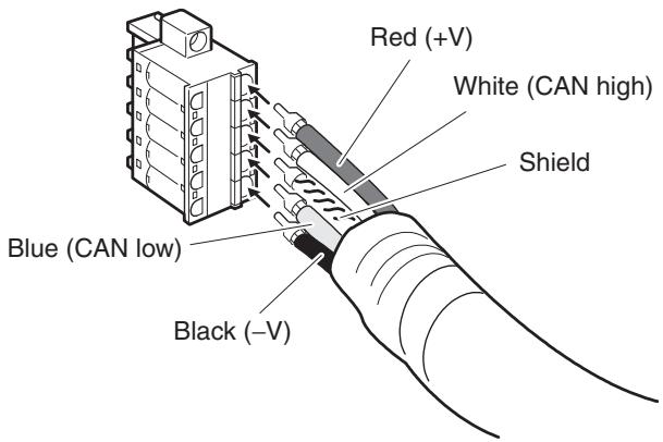
The colors correspond to the signal lines as follows:
| Color | Signal |
| Red | Power line, positive voltage (+V) |
| White | Communications line, high (CAN high) |
| --- | Shield |
| Blue | Communications line, low (CAN low) |
| Black | Communications cable, negative voltage (-V) |
- We recommend the following crimp terminals (for Thin Cables)
Power Lines: Phoenix Contact AI-series Crimp Terminals AI-0.5-6WH (product code 3200687)
Signal Lines: Phoenix Contact AI-series Crimp Terminals AI-0.25-6BU (product code 3201291)
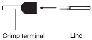
Insert the line and crimp.
The following crimp tool is also available.
Phoenix Contact ZA3 Crimp Tool
3-3-2 Attaching the DeviceNet Communications Unit Connector
Align the DeviceNet Communications Unit connector with the cable connector, and insert the cable connector fully into the DeviceNet Communications Unit connector.
Tighten the set screws to a torque between 0.25 and 0.3 N·m to secure the connector.
E5AR
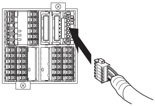
- Using the Connector Provided with the DeviceNet Communications Unit for a Multidrop Connection (Using Thin Cables)
- When using Thin Cables for a multidrop connection, two wires of the same color can be inserted into the one hole.
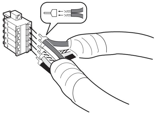
Crimp the two lines together that are to be inserted into the same hole using a special crimp terminal, as shown in the following diagram.
Crimp Terminal for Two Lines
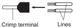
We recommend the following crimp terminals and crimp tools.
| Crimp terminal | Crimp tool |
| Phoenix Contact | Phoenix Contact |
| Model: AI-TWIN2×0.5-8WH (product code 3200933) | Model: UD6 (product code 1204436) |
3-3-3 Insulation Blocks
As shown in the following diagram, each function block of the E5AR/E5ER-DRT is electrically insulated.
The following are functionally insulated from each other: 1) each of the inputs, 2) event inputs, voltage outputs, and current outputs, and 3) communications.
The following are insulated from each other with basic insulation: 1) inputs, event inputs, voltage outputs, current outputs, communications, 2) relay output, and 3) transistor outputs.
If reinforced insulation is required, the input, event input, voltage output, current output, and communications terminals must be connected to devices that have no exposed chargeable parts and whose basic insulation is suitable for the applicable maximum voltage of connected parts.
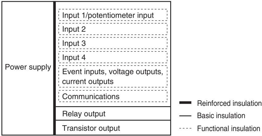
bar_stacked
| Power supply | Input 1/potentiometer input | Input 2 | Input 3 | Input 4 | Event inputs, voltage outputs, current outputs | Communications | Relay output | Transistor output | |---|---|---|---|---|---|---|---|---| | ■ Reinforced insulation | 0 | 0 | 0 | 0 | 0 | 0 | 0 | 0 | | — Basic insulation | 0 | 0 | 0 | 0 | 0 | 0 | 0 | 0 | | — Functional insulation | 0 | 0 | 0 | 0 | 0 | 0 | 0 | 0 |To comply with safety standards, always use an EN/IEC-compliant power supply with reinforced insulation or double insulation for the DeviceNet power supply.
SECTION 4
Remote I/O Communications
This section describes the input (IN) areas and output (OUT) areas that E5AR-DRT and E5ER-DRT Digital Controllers can use for remote I/O communications. The methods to allocate data for master communications are also described using sample programming.
4-1 Overview.... 4-2
4-2 I/O Allocation 4-2
4-2-1 Allocation Area Size.... 4-3
4-2-2 Allocation Parameters.... 4-3
4-2-3 Allocation Default Values.... 4-4
4-2-4 Allocation Data Size (IN Data Size and OUT Data Size) ..... 4-5
4-2-5 Allocation Settings 4-5
4-2-6 Input Data 4-11
4-2-7 Output Data.... 4-11
4-2-8 Operation Commands.... 4-12
4-3 Ladder Programming Examples 4-13
4-3-1 RUN/STOP Sample Programming 4-13
4-3-2 Change SP Sample Programming.... 4-16
4-1 Overview
I/O memory in the master can be allocated to data from the E5AR/ER-DRT Digital Controller, such as data from the Digital Controller's variable area, merely by specifying what Controller data is to be transferred to where.
Data is automatically exchanged between the master and Digital Controller, allowing the Digital Controller to be controlled and monitored from the master without requiring special communications programming.
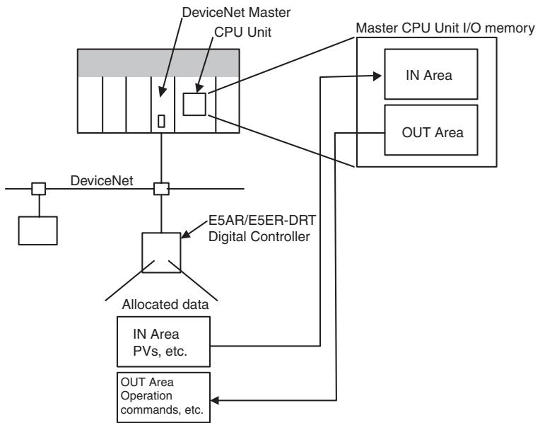
flowchart
graph TD
    A["DeviceNet"] --> B["DeviceNet Master CPU Unit"]
    B --> C["Master CPU Unit I/O memory"]
    C --> D["IN Area"]
    C --> E["OUT Area"]
    F["E5AR/E5ER-DRT Digital Controller"] --> G["Allocated data"]
    G --> H["IN Area PVs, etc."]
    G --> I["OUT Area Operation commands, etc."]
    J["DeviceNet"] --> K["DeviceNet"]
4-2 I/O Allocation
The Configurator can be used to select any data from the list of allocation parameters for the Digital Controller and then allocate the data in a user-set destination. Data is selected by specifying the allocation number assigned to the desired parameter.
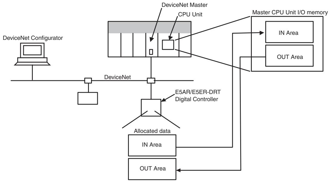
flowchart
graph TD
    A["DeviceNet Configurator"] --> B["DeviceNet"]
    B --> C["DeviceNet Master"]
    C --> D["CPU Unit"]
    D --> E["E5AR/E5ER-DRT Digital Controller"]
    E --> F["Allocated data"]
    F --> G["IN Area"]
    F --> H["OUT Area"]
    I["Master CPU Unit I/O memory"] --> J["IN Area"]
    I --> K["OUT Area"]
    C --> L["DeviceNet"]
4-2-1 Allocation Area Size
The size of allocated data in each of the IN and OUT Areas is shown in the following table.
| I/O memory | Words | Bytes | Setting | |
| Allocated data size: 2 bytes | Allocated data size: 4 bytes | |||
| IN Area | 0 to 100 | 0 to 200 | 100 | 50 |
| OUT Area | 0 to 100 | 0 to 200 | 100 | 50 |
Note
(1) When the master is a CS/CJ-series DeviceNet Unit, the IN Area can be divided into two areas (IN Area 1 and IN Area 2). Any allocation data from the list of parameters can be allocated in each area.
(2) The actual size of the allocated area depends on the size of allocation data selected.
(3) The default allocation data size is two bytes.
When the allocation data size is two bytes, the monitor and setting data will be displayed in the range FFFF hex to 0000 hex. Data will be fixed at 7FFF hex or 8000 hex if the data exceeds the range that can be displayed. For example, -32769 would be displayed as 8000 hex.
The following data sizes are fixed, however.
- General status: 2 bytes (fixed)
• E5AR/ER-DRT status: 4 bytes (fixed) - E5AR/ER-DRT Output Enable Bits and operation commands: 2 bytes (fixed)
Note
Refer to 4-2-6 Input Data on page 4-11 for details on General Status. Refer to 4-2-7 Output Data on page 4-11 for details on Output Enable Bits and operation commands.
Allocation data sizes are specified for the IN Area I/O allocations and OUT Area I/O allocations. If the allocation data size is 4 bytes, up to 50 allocations can be set. Any allocations set beyond that limit will be invalid. If the total allocated area for IN Area 1 and IN Area 2 exceeds the maximum number of words (100 words), the items allocated in IN Area 2 that exceed the maximum number of words will be invalid.
4-2-2 Allocation Parameters
The parameters that can be allocated are shown below. These parameters can be broadly classified as E5AR/ER-DRT status bits/operation commands, and E5AR/ER-DRT operation data and setting data.
- E5AR/ER-DRT Status Bits/Operation Commands The status bits and operation commands for the E5AR/ER-DRT Digital Controller are shown in the following table.
| Read | Write | Item |
| Yes | No | General status |
| No | Yes | Operation commands |
Note
(1) When items that are write-only are allocated in the IN Area, they are always set to 0.
(2) When items that are read-only are allocated in the OUT Area, they are allocated words in memory but operate the same as if they had not been allocated.
2. E5AR/ER-DRT Operation Data and Setting Data
Monitor values and setting data with communications addresses that belong to the following variable types can be allocated. Duplicate settings are possible and are processed in ascending order.
| Variable type | |
| C0 | Variable type C0 |
| C1 | Variable type C1 |
| C4 | Operation monitor |
| C6 | RUN level |
| C7 | Adjustment level |
| C8 | Adjustment 2 level |
| C9 | Bank setting level |
| CA | PID setting level |
| CB | Approximation setting level |
Note If items are allocated in the read-only area of the OUT Area, words are allocated in memory but operate as if they had not been allocated.
3. Output Enable Bits
Output Enable Bits are allocated in the first word of the OUT Area.
When Output Enable Bits are allocated in the IN Area, they are always set to 0 (OFF).
Note If data allocated to the IN or OUT Area is changed, use a software reset or cycle the power to enable the new settings.
4-2-3 Allocation Default Values
The default values for I/O allocations are listed in the following table.
| Area | Item | Allocation number |
| IN Area | PV (process value) | 3 |
| MV (manipulated variable) monitor (heating) | 13 | |
| Status (4 bytes) | 7 | |
| OUT Area | Output Enable Bits | -1 |
| SP (set point) | 9 | |
| Bank 0: Alarm 1 value | 81 | |
| Bank 0: Alarm 1 upper limit | 82 | |
| Bank 0: Alarm 1 lower limit | 83 | |
| Bank 0: Alarm 2 value | 84 | |
| Bank 0: Alarm 2 upper limit | 85 | |
| Bank 0: Alarm 2 lower limit | 86 | |
| Operation commands | 1 |
Note The above monitor values and settings are all for channel 1.
4-2-4 Allocation Data Size (IN Data Size and OUT Data Size)
| Setting range | Unit | Default |
| 2byte: 2 bytes4byte: 4 bytes | Bytes | 2 bytes |
4-2-5 Allocation Settings
The I/O allocation settings are listed in the following table.
Note Do not use allocation numbers that are reserved.
| Allocated to IN Area | Allocated to OUT Area | Allocation number (2-bytes decimal) | Item | Attribute | |||
| Channel 1 | Channel 2 | Channel 3 | Channel 4 | ||||
| No | Yes | -1 | --- | --- | --- | Output Enable Bits (Always 2 bytes) | --- |
| Yes | Yes | 0 | --- | --- | --- | Not used. | --- |
| No | Yes | 1 | --- | --- | --- | Operation command (Always 2 bytes) | --- |
| Yes | No | 2 | --- | --- | --- | General status (Always 2 bytes) | --- |
| Yes | No | 3 | 319 | 635 | 951 | PV | ch |
| Yes | No | 4 | 320 | 636 | 952 | Internal SP | ch |
| Yes | No | 5 | 321 | 637 | 953 | Bank No. monitor | ch |
| Yes | No | 6 | 322 | 638 | 954 | PID set No. monitor | ch |
| Yes | No | 7 | 323 | 639 | 955 | Status (Always 4 bytes) | ch |
| Yes | Yes | 8 | 324 | 640 | 956 | Manual MV | ch |
| Yes | Yes | 9 | 325 | 641 | 957 | SP | ch |
| Yes | No | 10 | 326 | 642 | 958 | Remote SP monitor | ch |
| Yes | No | 11 | 327 | 643 | 959 | Set point during SP ramp | ch |
| Yes | No | 13 | 329 | 645 | 961 | MV monitor (heating) | ch |
| Yes | No | 14 | 330 | 646 | 962 | MV monitor (cooling) | ch |
| Yes | No | 15 | 331 | 647 | 963 | Valve opening monitor | ch |
| Yes | Yes | 16 | 332 | 648 | 964 | Cooling coefficient | ch |
| Yes | Yes | 17 | 333 | 649 | 965 | (Reserved) | ch |
| Yes | Yes | 18 | 334 | 650 | 966 | (Reserved) | ch |
| Yes | Yes | 19 | 335 | 651 | 967 | (Reserved) | ch |
| Yes | Yes | 20 | 336 | 652 | 968 | Dead band | ch |
| Yes | Yes | 21 | 337 | 653 | 969 | Manual reset value | ch |
| Yes | Yes | 22 | 338 | 654 | 970 | Hysteresis (heating) | ch |
| Yes | Yes | 23 | 339 | 655 | 971 | Hysteresis (cooling) | ch |
| Yes | Yes | 24 | 340 | 656 | 972 | Control period (heating) | ch |
| Yes | Yes | 25 | 341 | 657 | 973 | Control period (cooling) | ch |
| Yes | Yes | 26 | 342 | 658 | 974 | Position proportional dead band | ch |
| Yes | Yes | 27 | 343 | 659 | 975 | Open/close hysteresis | ch |
| Yes | Yes | 28 | 344 | 660 | 976 | SP ramp time unit | ch |
| Yes | Yes | 29 | 345 | 661 | 977 | SP ramp rise value | ch |
| Yes | Yes | 30 | 346 | 662 | 978 | SP ramp fall value | ch |
| Yes | Yes | 31 | 347 | 663 | 979 | MV at stop (Normal/heating or cooling) | ch |
| Yes | Yes | 32 | 348 | 664 | 980 | MV at stop (position proportional) | ch |
| Yes | Yes | 33 | 349 | 665 | 981 | MV at PV error (normal/heating or cooling) | ch |
| Yes | Yes | 34 | 350 | 666 | 982 | MV at PV error (position proportional) | ch |
| Yes | Yes | 35 | 351 | 667 | 983 | MV change rate limit (heating) | ch |
| Yes | Yes | 36 | 352 | 668 | 984 | MV change rate limit (cooling) | ch |
| Yes | Yes | 37 | 353 | 669 | 985 | Input value 1 for input calibration | ch |
| Yes | Yes | 38 | 354 | 670 | 986 | Input correction 1 | ch |
| Yes | Yes | 39 | 355 | 671 | 987 | Input value 2 for input calibration | ch |
| Yes | Yes | 40 | 356 | 672 | 988 | Input correction 2 | ch |
| Yes | Yes | 41 | 357 | 673 | 989 | (Reserved) | ch |
| Yes | No | 46 | 362 | 678 | 994 | (Reserved) | Common |
| Yes | Yes | 47 | 363 | 679 | 995 | Disturbance gain | ch |
| Yes | Yes | 48 | 364 | 680 | 996 | Disturbance time constant | ch |
| Yes | Yes | 49 | 365 | 681 | 997 | Disturbance rectification constant | ch |
| Yes | Yes | 50 | 366 | 682 | 998 | Disturbance judgement width | ch |
| Yes | Yes | 51 | 367 | 683 | 999 | First order lag operation 1: Time constant | Common |
| Yes | Yes | 52 | 368 | 684 | 1000 | First order lag operation 2: Time constant | Common |
| Yes | Yes | 53 | 369 | 685 | 1001 | First order lag operation 3: Time constant | Common |
| Yes | Yes | 54 | 370 | 686 | 1002 | First order lag operation 4: Time constant | Common |
| Yes | Yes | 55 | 371 | 687 | 1003 | Move average 1: Number of measurement for moving average | Common |
| Yes | Yes | 56 | 372 | 688 | 1004 | Move average 2: Number of measurement for moving average | Common |
| Yes | Yes | 57 | 373 | 689 | 1005 | Move average 3: Number of measurement for moving average | Common |
| Yes | Yes | 58 | 374 | 690 | 1006 | Move average 4: Number of measurement for moving average | Common |
| Yes | Yes | 59 | 375 | 691 | 1007 | Extraction of square root operation 1: Low-cut point | Common |
| Yes | Yes | 60 | 376 | 692 | 1008 | Extraction of square root operation 2: Low-cut point | Common |
| Yes | Yes | 61 | 377 | 693 | 1009 | Extraction of square root operation 3: Low-cut point | Common |
| Yes | Yes | 62 | 378 | 694 | 1010 | Extraction of square root operation 4: Low-cut point | Common |
| Yes | Yes | 63 | 379 | 695 | 1011 | Analog parameter 1 (Control ratio) | Common |
| Yes | Yes | 64 | 380 | 696 | 1012 | (Reserved) | Common |
| Yes | Yes | 65 | 381 | 697 | 1013 | (Reserved) | Common |
| Yes | Yes | 66 | 382 | 698 | 1014 | (Reserved) | Common |
| Yes | Yes | 67 | 383 | 699 | 1015 | (Reserved) | Common |
| Yes | Yes | 68 | 384 | 700 | 1016 | (Reserved) | Common |
| Yes | Yes | 69 | 385 | 701 | 1017 | (Reserved) | Common |
| Yes | Yes | 70 | 386 | 702 | 1018 | (Reserved) | Common |
| Yes | Yes | 71 | 387 | 703 | 1019 | (Reserved) | Common |
| Yes | Yes | 72 | 388 | 704 | 1020 | (Reserved) | Common |
| Yes | Yes | 73 | 389 | 705 | 1021 | (Reserved) | Common |
| Yes | Yes | 74 | 390 | 706 | 1022 | (Reserved) | Common |
| Yes | Yes | 75 | 391 | 707 | 1023 | (Reserved) | Common |
| Yes | Yes | 76 | 392 | 708 | 1024 | (Reserved) | Common |
| Yes | Yes | 77 | 393 | 709 | 1025 | (Reserved) | Common |
| Yes | Yes | 78 | 394 | 710 | 1026 | (Reserved) | Common |
| Yes | Yes | 79 | 395 | 711 | 1027 | Bank 0: LSP | ch |
| Yes | Yes | 80 | 396 | 712 | 1028 | Bank 0: PID set No. | ch |
| Yes | Yes | 81 | 397 | 713 | 1029 | Bank 0: Alarm 1 value | ch |
| Yes | Yes | 82 | 398 | 714 | 1030 | Bank 0: Alarm 1 upper limit | ch |
| Yes | Yes | 83 | 399 | 715 | 1031 | Bank 0: Alarm 1 lower limit | ch |
| Yes | Yes | 84 | 400 | 716 | 1032 | Bank 0: Alarm 2 value | ch |
| Yes | Yes | 85 | 401 | 717 | 1033 | Bank 0: Alarm 2 upper limit | ch |
| Yes | Yes | 86 | 402 | 718 | 1034 | Bank 0: Alarm 2 lower limit | ch |
| Yes | Yes | 87 | 403 | 719 | 1035 | Bank 0: Alarm 3 value | ch |
| Yes | Yes | 88 | 404 | 720 | 1036 | Bank 0: Alarm 3 upper limit | ch |
| Yes | Yes | 89 | 405 | 721 | 1037 | Bank 0: Alarm 3 lower limit | ch |
| Yes | Yes | 90 | 406 | 722 | 1038 | Bank 0: Alarm 4 value | ch |
| Yes | Yes | 91 | 407 | 723 | 1039 | Bank 0: Alarm 4 upper limit | ch |
| Yes | Yes | 92 | 408 | 724 | 1040 | Bank 0: Alarm 4 lower limit | ch |
| Yes | Yes | 93 | 409 | 725 | 1041 | Bank 1: LSP | ch |
| Yes | Yes | Same as for bank 1 for 94, 410, 726, and 1042 on. | ch | ||||
| Yes | Yes | 106 | 422 | 738 | 1054 | Bank 1: Alarm 4 lower limit | ch |
| Yes | Yes | 107 | 423 | 739 | 1055 | Bank 2: LSP | ch |
| Yes | Yes | Same as for bank 1. | ch | ||||
| Yes | Yes | 120 | 436 | 752 | 1068 | Bank 2: Alarm 4 lower limit | ch |
| Yes | Yes | 121 | 437 | 753 | 1069 | Bank 3: LSP | ch |
| Yes | Yes | Same as for bank 1 for 122, 438, 754, and 1070 on. | ch | ||||
| Yes | Yes | 134 | 450 | 766 | 1082 | Bank 3: Alarm 4 lower limit | ch |
| Yes | Yes | 135 | 451 | 767 | 1083 | Bank 4: LSP | ch |
| Yes | Yes | Same as for bank 1 for 136, 452, 768, and 1084 on. | ch | ||||
| Yes | Yes | 148 | 464 | 780 | 1096 | Bank 4: Alarm 4 lower limit | ch |
| Yes | Yes | 149 | 465 | 781 | 1097 | Bank 5: LSP | ch |
| Yes | Yes | Same as for bank 1 for 150, 466, 782, and 1098 on. | ch | ||||
| Yes | Yes | 162 | 478 | 794 | 1110 | Bank 5: Alarm 4 lower limit | ch |
| Yes | Yes | 163 | 479 | 795 | 1111 | Bank 6: LSP | ch |
| Yes | Yes | Same as for bank 1 for 164, 480, 796, and 1112 on. | ch | ||||
| Yes | Yes | 176 | 492 | 808 | 1124 | Bank 6: Alarm 4 lower limit | ch |
| Yes | Yes | 177 | 493 | 809 | 1125 | Bank 7: LSP | ch |
| Yes | Yes | Same as for bank 1 for 178, 493, 809, and 1126 on. | ch | ||||
| Yes | Yes | 190 | 506 | 822 | 1138 | Bank 7: Alarm 4 lower limit | ch |
| Yes | Yes | 191 | 507 | 823 | 1139 | PID 1: Proportional band | ch |
| Yes | Yes | 192 | 508 | 824 | 1140 | PID 1: Integral time | ch |
| Yes | Yes | 193 | 509 | 825 | 1141 | PID 1: Derivative time | ch |
| Yes | Yes | 194 | 510 | 826 | 1142 | PID 1: Integral time (0.01 s unit) | ch |
| Yes | Yes | 195 | 511 | 827 | 1143 | PID 1: Derivative time (0.01 s unit) | ch |
| Yes | Yes | 196 | 512 | 828 | 1144 | PID 1: MV upper limit | ch |
| Yes | Yes | 197 | 513 | 829 | 1145 | PID 1: MV lower limit | ch |
| Yes | Yes | 198 | 514 | 830 | 1146 | PID 1: Automatic selection range upper limit | ch |
| Yes | Yes | 199 | 515 | 831 | 1147 | PID 1: Automatic selection range lower limit | ch |
| Yes | Yes | 200 | 516 | 832 | 1148 | PID 2: Proportional band | ch |
| Yes | Yes | Same as for PID 1 for 201, 517, 833, and 1149 on. | ch | ||||
| Yes | Yes | 208 | 524 | 840 | 1156 | PID 2: Automatic selection range upper limit | ch |
| Yes | Yes | 209 | 525 | 841 | 1157 | PID 3: Proportional band | ch |
| Yes | Yes | Same as for PID 1 for 210, 526, 842, and 1158 on. | ch | ||||
| Yes | Yes | 217 | 533 | 849 | 1165 | PID 3: Automatic selection range upper limit | ch |
| Yes | Yes | 218 | 534 | 850 | 1166 | PID 4: Proportional band | ch |
| Yes | Yes | Same as for PID 1 for 219, 535, 851, and 1167 on. | ch | ||||
| Yes | Yes | 226 | 542 | 858 | 1174 | PID 4: Automatic selection range upper limit | ch |
| Yes | Yes | 227 | 543 | 859 | 1175 | PID 5: Proportional band | ch |
| Yes | Yes | Same as for PID 1 for 228, 544, 860, and 1176 on. | ch | ||||
| Yes | Yes | 235 | 551 | 867 | 1183 | PID 5: Automatic selection range upper limit | ch |
| Yes | Yes | 236 | 552 | 868 | 1184 | PID 6: Proportional band | ch |
| Yes | Yes | Same as for PID 1 for 237, 553, 869, and 1185 on. | ch | ||||
| Yes | Yes | 244 | 560 | 876 | 1192 | PID 6: Automatic selection range upper limit | ch |
| Yes | Yes | 245 | 561 | 877 | 1193 | PID 7: Proportional band | ch |
| Yes | Yes | Same as for PID 1 for 246, 562, 878, and 1194 on. | ch | ||||
| Yes | Yes | 253 | 569 | 885 | 1201 | PID 7: Automatic selection range upper limit | ch |
| Yes | Yes | 254 | 570 | 886 | 1202 | PID 8: Proportional band | ch |
| Yes | Yes | Same as for PID 1 for 255, 571, 887, and 1203 on. | ch | ||||
| Yes | Yes | 262 | 578 | 894 | 1210 | PID 8: Automatic selection range upper limit | ch |
| Yes | Yes | 263 | 579 | 895 | 1211 | Straight-line 1 approximation: Input 1 | Common |
| Yes | Yes | 264 | 580 | 896 | 1212 | Straight-line 1 approximation: Input 2 | Common |
| Yes | Yes | 265 | 581 | 897 | 1213 | Straight-line 1 approximation: Output 1 | Common |
| Yes | Yes | 266 | 582 | 898 | 1214 | Straight-line 1 approximation: Output 2 | Common |
| Yes | Yes | 267 | 583 | 899 | 1215 | Straight-line 2 approximation: Input 1 | Common |
| Yes | Yes | 268 | 584 | 900 | 1216 | Straight-line 2 approximation: Input 2 | Common |
| Yes | Yes | 269 | 585 | 901 | 1217 | Straight-line 2 approximation: Output 1 | Common |
| Yes | Yes | 270 | 586 | 902 | 1218 | Straight-line 2 approximation: Output 2 | Common |
| Yes | Yes | 271 | 587 | 903 | 1219 | (Reserved) | Common |
| Yes | Yes | 272 | 588 | 904 | 1220 | (Reserved) | Common |
| Yes | Yes | 273 | 589 | 905 | 1221 | (Reserved) | Common |
| Yes | Yes | 274 | 590 | 906 | 1222 | (Reserved) | Common |
| Yes | Yes | 275 | 591 | 907 | 1223 | (Reserved) | Common |
| Yes | Yes | 276 | 592 | 908 | 1224 | (Reserved) | Common |
| Yes | Yes | 277 | 593 | 909 | 1225 | (Reserved) | Common |
| Yes | Yes | 278 | 594 | 910 | 1226 | (Reserved) | Common |
| Yes | Yes | 279 | 595 | 911 | 1227 | Broken-line 1 approximation: Input 1 | Common |
| Yes | Yes | Same pattern as for straight-line 1 approximation for 280, 596, 912, and 1228 on. | Common | ||||
| Yes | Yes | 298 | 614 | 930 | 1246 | Broken-line 1 approximation: Input 20 | Common |
| Yes | Yes | 299 | 615 | 931 | 1247 | Broken line 1 approximation: Output 1 | Common |
| Yes | Yes | Same pattern as for straight-line 1 approximation for 300, 616, 932, and 1248 on. | Common | ||||
| Yes | Yes | 318 | 634 | 950 | 1266 | Broken line 1 approximation: Output 20 | Common |
E5□R Status
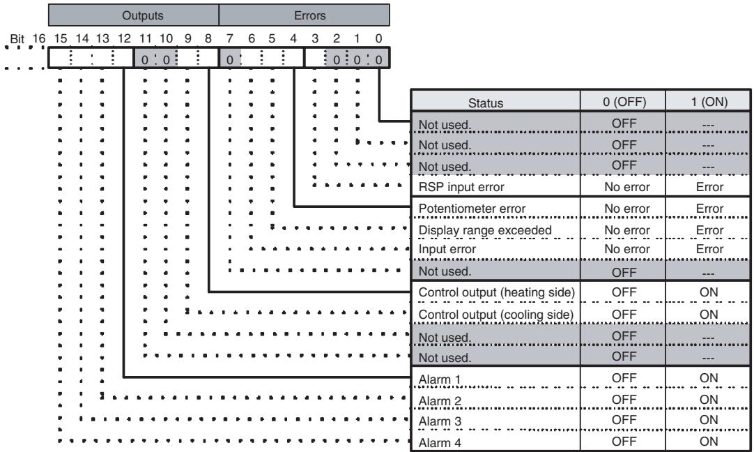
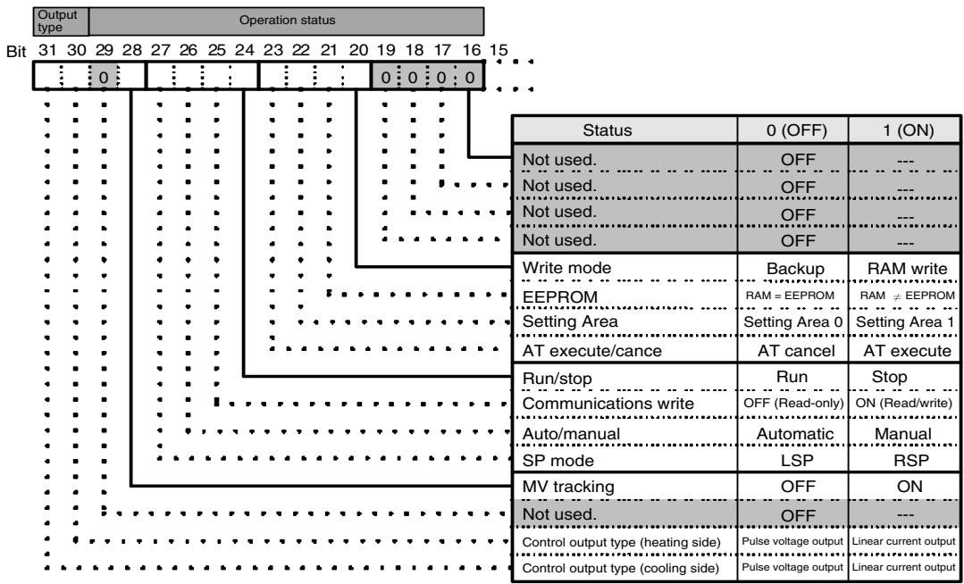
Note: The status for Setting Area 1 would be as follows when read:
- RSP input error: Clear
- Potentiometer error: Clear
- Display range exceeded: Clear
- Input error: Clear
- AT: Clear
- Run/stop: ON (Stop)
• Auto/manual: Hold previous value - SP mode, MV tracking: Refresh
- Control output (heating side) and control output (cooling side): Clear
- Alarm 1, alarm 2, alarm 3, and alarm 4: Clear
- Control output type (heating), control output type (cooling): Refresh
Note (a) Position-proportional models have an open output for control output (heating side) and a closed output for control output (cooling side).
(b) Control output (both heating and cooling sides) is always OFF for linear outputs.
(c) Either the control output (heating) or control output (cooling) is OFF for pulse voltage outputs, depending on the control output type.
4-2-6 Input Data
The input data specific to Digital Controllers with DeviceNet communications that is not allocated in the variable area of the E5AR/ER-DRT is described here.
General Status (Setting: 2)
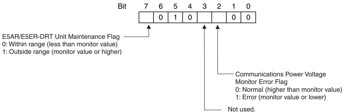
- The Communications Power Voltage Monitor Error Flag indicates the status of the power being supplied through the DeviceNet communications cable.
- The Unit Maintenance Flag is set to 1 when the total ON time or run time of the E5AR/ER-DRT Digital Controller exceeds the monitor value.
4-2-7 Output Data
Output data specific to DeviceNet that is not allocated to the E5AR/E5ER variable area is described here.
Output Enable Bits
Output Enable Bits are used when settings are written to the OUT Area, e.g., when SP are set or RUN/STOP is executed using operation commands. The area for Output Enable Bits is always allocated in the first word of the OUT Area.
When Output Enable Bits are set to 0 (OFF), the settings and bits set in the OUT Area are not transmitted and, therefore, nothing is executed. The settings can be executed by setting the Output Enable Bits to 1 (ON). Writing is not executed if the Output Enable Bits are not set to 1.
Setting Output Enable Bits prevents unintentional setting changes and enables various settings in the OUT Area to be enabled simultaneously. For example, a new value may written to a word for which a SP has already been set. If the Output Enable Bits are set to 1 and then set to 0, no SP will be written even if one is accidentally allocated. (However, care must be taken because writing is enabled if Output Enable Bits are set to 1.)
Furthermore, if set values are written for all the channels and the Output Enable Bits are set to 1, the set values will all be enabled at once.
Note When Output Enable Bits are set to 1, data allocated to the OUT Area is written whenever it changes.
4-2-8 Operation Commands
Operation commands are used to RUN and STOP, to move to setting area 1, and other similar operations. As shown in the following table, operation commands are executed using a combination of command codes, related information, and strobes.
| Command code | Details | Related information | Memory write area | |
| Upper byte | Lower byte | |||
| 00 | Communications write | 0 (See note 1.) | 0: OFF (Read only)1: ON (Read/write) | Non-volatile memory |
| 01 | RUN/STOP | 0 to 3, F (See note 2.) | 0: Run; 1: Stop | Depends on write mode. |
| 02 | Bank selection | 0 to 3, F (See note 2.) | 0 to 7: Bank 0 to bank 7 | Depends on write mode. |
| 03 | AT execute | 0 to 3, F (See note 2.) | 0: Current PID set number1 to 8: PID set number | Does not write data. |
| 04 | Write mode | 0 (See note 1.) | 0: Backup mode1: RAm write mode | Non-volatile memory |
| 05 | RAM data save | 0 (See note 1.) | 0 | Non-volatile memory |
| 06 | Software reset | 0 (See note 1.) | 0 | Does not write data. |
| 07 | Move to Setting Area 1 | 0 (See note 1.) | 0 | Does not write data. |
| 08 | Move to protect level | 0 (See note 1.) | 0 | Does not write data. |
| 09 | Auto/manual | 0 to 3, F (See note 2.) | 0: Auto mode1: Manual mode | Depends on write mode. |
| 0A | AT cancel | 0 to 3, F (See note 2.) | 0: Cancel | Does not write data. |
| 0B | Initialize setting | 0 (See note 1.) | 0 | Non-volatile memory |
| 0C | Latch reset | 0 to 3, F (See note 2.) | 0 | Does not write data. |
| 0D | SP mode | 0 to 3, F (See note 2.) | 0: LSP; 1: RSP | Depends on write mode. |
Note
(1) Operations apply to all channels.
(2) The channel is specified.
0: Channel 1; 1: Channel 2; 2: Channel 3; 3: Channel 4; F: All channels
(3) The write mode defaults are in backup mode.
Operation commands are created as shown in the following diagram.
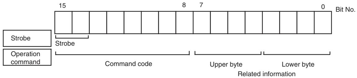
Bit 15 is strobe 2 and bit 14 is strobe 1. A logical OR is taken between the two leftmost bits of the command code and bits 15 and 14, and the result is attached as the strobe to the operation command. The command code for E5AR/ER operation commands is 0□ hex, so when the logical OR is 8□ hex, the strobe is ON.
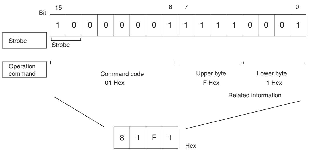
With the CS1W-DRM21 and CJ1W-DRM21DeviceNet Units, operation commands are made ready for execution by writing to the allocated words (CIO 3209 when the default I/O allocation (fixed allocation area 1) is set.)
Operation commands are executed only when the Output Enable Bit is set to 1 (ON) and the strobe is ON. The strobe is ON when the following two conditions are met:
- Strobe 2 = 1 and strobe 1 = 0
- The strobe was cleared after the previous operation command was executed.
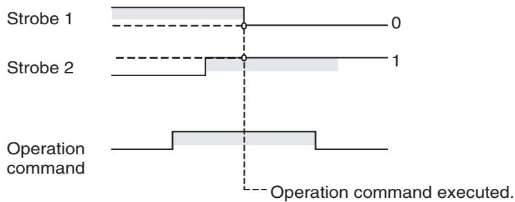
other
| Operation command | Start | End | | ----------------- | ----- | --- | | Strobe 1 | 0 | 1 | | Strobe 2 | 0 | 1 |Note Software resets are executed again even if the strobe has not been cleared. Therefore the Output Enable Bit or the strobe must be cleared after the software reset command has been sent.
4-3 Ladder Programming Examples
4-3-1 RUN/STOP Sample Programming
The RUN/STOP ladder programming example here is executed under the following conditions.
- Using default I/O allocations to allocate data in fixed allocation area 1 of a CS/CJ-series DeviceNet Unit (OUT Area = CIO 3200 to CIO 3263, IN Area = CIO 3300 to CIO 3363).
Outline This ladder programming example executes RUN and STOP for the E5AR/ER-DRT. RUN and STOP are executed using operation commands.
Output Enable Bit (CIO 320100) and strobe are used to execute the operation command.
Operation
- First, the Output Enable Bit is turned ON. The hexadecimal values are set to D1000 and D1001 at the start of the ladder program. These values prepare the channel 1 RUN operation command 0100 hex and the STOP operation command 0101 hex.
- RUN is executed for channel 1 when CIO 000000 turns ON.
- The contents of D1000 (= 0100 hex) is copied to CIO 3209, where the operation command is allocated.
- The strobe is turned ON (strobe 1 = 0 and strobe 2 = 1) and the operation command is executed. The RUN/STOP status is checked and the strobe is disabled for RUN (to prevent unintentional setting changes.)
- STOP is executed when CIO 000100 turns ON. The contents of D1000 (= 0100 hex) is copied to CIO 3209, where the operation command is allocated.
■ Programming Example
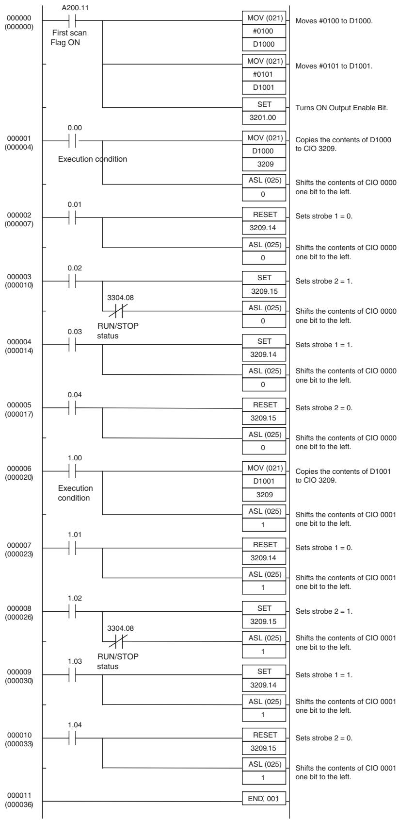
flowchart
graph TD
    A["000000 (000000)"] --> B["A200.11"]
    B --> C["First scan Flag ON"]
    C --> D["MOV (021)"]
    D --> E["#0100 to D1000."]
    C --> F["D1000"]
    F --> G["MOV (021)"]
    G --> H["#0101 to D1001."]
    C --> I["D1001"]
    I --> J["SET"]
    J --> K["3201.00"]
    K --> L["Turns ON Output Enable Bit."]
    M["000001 (000004)"] --> N["Execution condition"]
    N --> O["MOV (021)"]
    O --> P["D1000 to CIO 3209."]
    N --> Q["ASL (025)"]
    Q --> R["Shifts the contents of CIO 0000 one bit to the left."]
    S["000002 (000007)"] --> T["0.01"]
    T --> U["RESET"]
    U --> V["3209.14"]
    T --> W["ASL (025)"]
    W --> X["Sets strobe 1 = 0."]
    Y["000003 (000010)"] --> Z["3304.08 RUN/STOP status"]
    Z --> AA["SET"]
    AA --> AB["3209.15"]
    Z --> AC["ASL (025)"]
    AC --> AD["Sets strobe 2 = 1."]
    AE["000004 (000014)"] --> AF["SET"]
    AF --> AG["3209.14"]
    AF --> AH["ASL (025)"]
    AH --> AI["Sets strobe 1 = 1."]
    AJ["000005 (000017)"] --> AK["RESET"]
    AK --> AL["3209.15"]
    AK --> AM["ASL (025)"]
    AM --> AN["Sets strobe 2 = 0."]
    AO["000006 (000020)"] --> AP["Execution condition"]
    AP --> AQ["MOV (021)"]
    AQ --> AR["D1001 to CIO 3209."]
    AP --> AS["ASL (025)"]
    AS --> AT["Shifts the contents of CIO 0001 one bit to the left."]
    AU["000007 (000023)"] --> AV["1.01"]
    AV --> AW["RESET"]
    AW --> AX["3209.14"]
    AV --> AY["ASL (025)"]
    AY --> AZ["Sets strobe 1 = 0."]
    BA["000008 (000026)"] --> BB["1.02"]
    BB --> BC["SET"]
    BC --> BD["3209.15"]
    BB --> BE["ASL (D1) to CIO 32"]
    BC --> BF["Sets strobe 2 = 1."]
    BG["000009 (0003) "] --> BH["RUN/STOP status"]
    BH --> BI["SET"]
    BI --> BJ["3209.14"]
    BH --> BK["ASL (D1) to CIO 32"]
    BH --> BL["Sets strobe 1 = 1."]
    BM["00011 (D) 36"] --> BN["END (D)"]
    BN --> BO["Set"]
    BO --> BP["32O9.15"]
    BN --> BQ["ASL (D) to CIO 32"]
4-3-2 Change SP Sample Programming
The ladder programming example here is for setting and changing SP. The program is for execution under the following conditions.
- Using simple I/O allocation to allocate data in fixed allocation area 1 of a CS/CJ-series DeviceNet Unit of CS/CJ-series DeviceNet Unit (OUT Area = CIO 3200 to CIO 3263, IN Area = CIO 3300 to CIO 3363).
Outline
This ladder program example sets and changes the SP for the E5AR/ER-DRT.
Output Enable Bit (CIO 320100) is used to write SP.
Operation
- The value used as SP is set in D1000 and D1001 at the start of the ladder program. In this example, the SP is set to 100.0, so the hexadecimal number 03E8 is written to D1000.
- Once the execution condition (CIO000000) turns ON, the SP is set to CIO 3202.
- The Output Enable Bit (CIO320200) is turned ON and the SP is written.
- A timer is used to turn OFF the Output Enable Bit after 0.1 s (see note).
Note: If using this kind of ladder programming, do not use the timer method shown here. Instead, allocate the SP, check that the setting has changed, and then turn OFF the Output Enable Bit using the following steps.
- Use a Configurator or other Programming Device to allocate the SP to the IN Area.
- Check that the SP has been written and then turn OFF the Output Enable Bit.
Programming Example
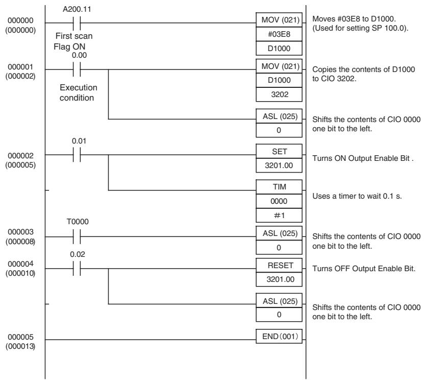
flowchart
graph TD
    A["A200.11"] --> B["First scan Flag ON 0.00"]
    B --> C["Execution condition"]
    C --> D["MOV (021)"]
    D --> E["#03E8"]
    E --> F["D1000"]
    F --> G["Moves #03E8 to D1000. (Used for setting SP 100.0)."]
    G --> H["Copies the contents of D1000 to CIO 3202."]
    H --> I["D1000 3202"]
    I --> J["ASL (025) 0"]
    J --> K["Shifts the contents of CIO 0000 one bit to the left."]
    K --> L["TUM ON Output Enable Bit ."]
    L --> M["SET 3201.00"]
    M --> N["TIM 0000 #1"]
    N --> O["Uses a timer to wait 0.1 s."]
    O --> P["ASL (025) 0"]
    P --> Q["Shifts the contents of CIO 0000 one bit to the left."]
    Q --> R["RESET 3201.00"]
    R --> S["Turns OFF Output Enable Bit."]
    S --> T["ASL (025) 0"]
    T --> U["Shifts the contents of CIO 0000 one bit to the left."]
    U --> V["END(001)"]
SECTION 5
Explicit Message Communications
This section describes how to send explicit messages to the E5AR/E5ER-DRT Digital Controller, including how to send CompoWay/F commands using explicit messages.
5-1 Overview of Explicit Message Communications 5-2
5-1-1 Explicit Message Communications 5-2
5-1-2 Explicit Message Types 5-2
5-1-3 Explicit Messages Basic Format.... 5-3
5-2 Sending CompoWay/F Commands to the Digital Controller 5-4
5-2-1 CompoWay/F Binary Commands.... 5-5
5-2-2 CompoWay/F ASCII Commands 5-5
5-3 Explicit Messages Specific to DeviceNet-compatible Digital Controllers . . . 5-6
5-3-1 Reading General Status. 5-7
5-3-2 Writing Maintenance Mode Data 5-7
5-3-3 Setting and Monitoring the Digital Controller Channels ..... 5-7
5-1 Overview of Explicit Message Communications
5-1-1 Explicit Message Communications
Explicit message communications is a communications protocol for sending commands from the master as explicit messages, and receiving explicit messages as responses from the nodes that receive the commands.
Explicit messages can be sent from the master to the Digital Controller to read and write the E5AR/E5ER Digital Controller variable area, send operation commands, and read and write various other DeviceNet functions supported by the Digital Controller.
Explicit message communications can be used to send and receive data that is not allocated in the IN and OUT Areas due to word size restrictions, and data that does not require the frequent refreshing used by the IN Area and OUT Area.
Use either of the following two methods depending on the application.
Reading/Writing E5AR/E5ER Variable Area Data and Sending Operation Commands
Send CompoWay/F communications commands to E5AR/E5ER Digital Controllers by embedding them in explicit messages.
Reading/Writing E5AR/E5ER-DRT Maintenance Information
Send explicit messages specific to the DeviceNet-compatible Digital Controller.
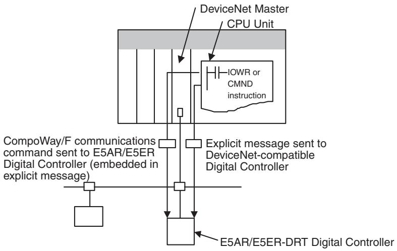
flowchart
graph TD
    A["DeviceNet Master"] --> B["CPU Unit"]
    B --> C["IOWR or CMND instruction"]
    C --> D["Explicit message sent to DeviceNet-compatible Digital Controller"]
    D --> E["E5AR/E5ER-DRT Digital Controller"]
    F["CompoWay/F communications command sent to E5AR/E5ER Digital Controller (embedded in explicit message)"] --> G["Computer"]
    H["Computer"] --> I["Computer"]
    J["Computer"] --> K["Computer"]
5-1-2 Explicit Message Types
The explicit messages sent to the Digital Controller can be divided into two types: messages in which CompoWay/F commands are embedded and messages specific to DeviceNet-compatible Digital Controllers.
Sending CompoWay/F Commands to the E5AR/E5ER-DRT (Embedded in Explicit Messages)
The master can send CompoWay/F communications commands to the E5AR/E5ER Digital Controller by sending them as explicit message data.
When DeviceNet-compatible Digital Controllers are used, the explicit messages are automatically converted to CompoWay/F communications commands and sent to the E5AR/E5ER-DRT Digital Controller. The responses from the Digital Controller are converted into explicit messages and returned to the master. CompoWay/F commands are used to read from and write to the E5AR/E5ER variable area and to execute operation commands.
CompoWay/F commands consist of binary commands and ASCII commands.
■ CompoWay/F Binary Commands
CompoWay/F binary commands are CompoWay/F communications commands expressed in hexadecimal, and are easy to execute from ladder programs. CompoWay/F communications commands that include ASCII data, however, cannot be sent or received. Therefore, Read Controller Attribute (0503) and broadcasting (unit number = XX) cannot be used.
■ CompoWay/F ASCII Commands
CompoWay/F ASCII commands are CompoWay/F communications commands expressed in ASCII, so numerical values must be converted to ASCII when executing these commands from a ladder program. CompoWay/F binary commands cannot be used. Broadcasting (unit number = XX) cannot be used, but all other CompoWay/F communications commands can be sent and received, including Read Controller Attribute (05 03), which cannot be used with CompoWay/F binary commands.
Sending Explicit Messages Specific to DeviceNet-compatible Digital Controllers
The master can send explicit messages to a DeviceNet-compatible Digital Controller to control various operations supported only by DeviceNet-compatible Digital Controllers and to read DeviceNet-specific settings and status information.
These explicit messages are used to read and write maintenance information specific to DeviceNet-compatible Digital Controllers.
5-1-3 Explicit Messages Basic Format
The basic formats of explicit message commands and responses are described here.
Command Block
| Destination node address | Service code | Class ID | Instance ID | Attribute ID | Data |
Destination Node Address
This parameter specifies the node address of the Controller to which the explicit messages (commands) will be sent in single-byte (2-digit) hexadecimal.
Service Code, Class ID, Instance ID, Attribute ID
These parameters specify the command type, processing target, and processing details.
The Attribute ID does not need to be specified for some commands.
Data
Specifies the details of the commands, set values, etc. The data section is not required for read commands.
Response Block
The following format is used when a normal response is returned for the sent explicit message.
| No. of bytes received | Source node address | Service code | Data |
The following format is used when an error response is returned for the sent explicit message.
| No. of bytes received0004 hex, fixed | Source node address | Service code | Error code(2 bytes, fixed) |
Number of Bytes Received
The number of data bytes received from the source node address is returned as a hexadecimal. When an error response is returned for the explicit message, the contents is always 0004 hex.
Source Node Address
The node address of the master that sent the explicit message is returned as a hexadecimal.
Service Code
For normal responses, the service code specified in the command turns with the most significant bit (bit 07) turned ON is returned. (For example, when the service code of the command is 0E hex, the service code of the response will be 8E hex.) When an error response is returned for the explicit message, the service code is always 94 hex.
Data
Read data is included in the response only when a read command is executed. There is no data for commands that do not read data.
Error Code
The following table shows the error codes for explicit messages.
| Error code | Error name | Cause |
| 08FF | Service not supported | The service code is incorrect. |
| 09FF | Invalid Attribute value | The Attribute Value is not supported. |
| 16FF | Object does not exist | The Instance ID is not supported. |
| 15FF | Too much data | The data string is too long. |
| 13FF | Not enough data | The data string is too short. |
| 14FF | Attribute not supported | The Attribute ID is not supported. |
| 0CFF | Object state conflict | The command cannot be executed. |
| 0EFF | Attribute not settable | A write service code was sent for a read-only Attribute ID. |
| 20** | Invalid Parameter | There is an error in the specified parameter. |
5-2 Sending CompoWay/F Commands to the Digital Controller
The master can send CompoWay/F command frames to the E5AR/E5ER-DRT Digital Controller by embedding them in explicit message commands, and receive CompoWay/F response frames that are embedded in explicit messages responses.
The following services, however, cannot be used.
• Monitor value/set data composite registration read
- Monitor value/set data composite read registration (write)
- Monitor value/set data composite read registration confirmation (read)
5-2-1 CompoWay/F Binary Commands
CompoWay/F binary commands use hexadecimal values for the CompoWay/F frames, and not ASCII. Therefore, the data volume is about half of CompoWay/F ASCII commands. The following restrictions apply.
- Read Controller Attribute (05 03), which includes ASCII in the Compo-Way/F frame, cannot be used.
The following command and response formats are used when executing CompoWay/F binary commands from an OMRON Master.
Command Block
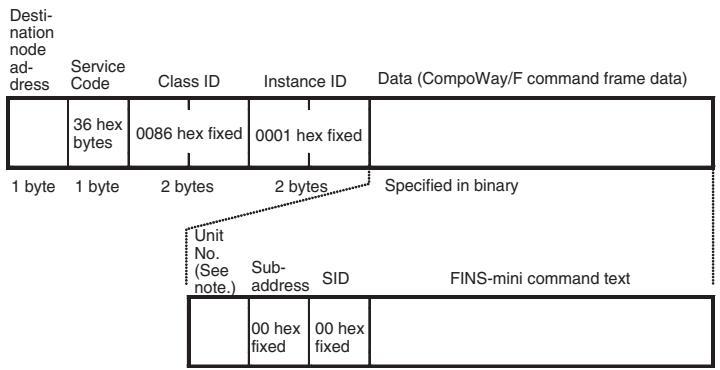
Note Specify the same value as the destination node address. Broadcasting cannot be specified.
Response Block
Normal Response
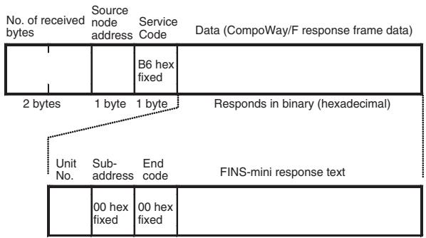
5-2-2 CompoWay/F ASCII Commands
When CompoWay/F ASCII commands are used, the CompoWay/F frames are expressed in ASCII (each digit in a specified numerical value is also converted to ASCII, so 52 is specified as ASCII 3532).
The following command and response formats are used when the commands are executed from an OMRON Master Unit.
Command Block
![Destination node address Service Code Class ID Instance ID Data (CompoWay/F command frame data) 37 hex fixed 0086 hex fixed 0001 hex fixed 1 byte 1 byte 2 bytes 2 bytes Specified in ASCII Unit No. (See note.) Sub-address SID FINS-mini command text [00]= 3030 hex fixed [0]= 30 hex fixed](/content/2025/01/168380/images/8507ef50786f2c1aa675bb353c500aa07272b24fb29d8daa791707f72c1eed33.jpg)
Note Specify the same value as the destination node address. Broadcasting cannot be specified.
Response Block
Normal Response
![No. of receive bytes Source node address Service Code Data (CompoWay/F response frame data) 2 bytes 1 byte 1 byte Returns in ASCII Unit No. Sub-address End code FINS-mini response text [00]= 3030 Hex fixed](/content/2025/01/168380/images/8ec06f7e574e15483e51bfaa29e899d5a53a7cfbf956fa7a1f27b607ac66bab1.jpg)
5-3 Explicit Messages Specific to DeviceNet-compatible Digital Controllers
The following list shows explicit messages that can be sent to E5AR/E5ER-DRT Digital Controllers. These messages are used to read and write maintenance information (such as Unit conduction time or total RUN time) for the DeviceNet-compatible Digital Controller.
For details on sending explicit messages from an OMRON Master PLC, refer to the DeviceNet Master Unit operation manual.
Note The number of digits used for the Class ID, Instance ID, and Attribute ID depends on the master used. When sending parameters from an OMRON Master Unit, the values are expressed as follows:
Class ID: 4-digit (2-byte) hexadecimal
Instance ID: 4-digit (2-byte) hexadecimal
Attribute ID: 2-digit (1-byte) hexadecimal
5-3-1 Reading General Status
| Explicit message | Read/write | Function | Command | Response | ||||
| Service code | Class ID | Instance ID | Attribute ID | Data size | ||||
| General Status Read | Read | Reads the DeviceNet-compatible Controller's general status bits (8 bits). (Refer to page 4-11). | 0E hex | 95 hex | 01 hex | 65 hex | --- | 1 byte |
5-3-2 Writing Maintenance Mode Data
| Explicit message | Read/write | Function | Command | Response | ||||
| Service code | Class ID | Instance ID | Attribute ID | Data size | ||||
| Maintenance Counter Save | Save | Records the maintenance counter (PV of total ON/RUN time for all Digital Controllers) in memory. | 16 hex | 95 hex | 01 hex | 75 hex | --- | --- |
5-3-3 Setting and Monitoring the Digital Controller Channels
| Explicitmessage | Read/write | Function | Command | Response | ||||
| Servicecode | ClassID | InstanceID | AttributeID | Data size | ||||
| Digital Controller Channel Maintenance Information Monitor Mode | Read | Reads the monitor mode for maintenance information of the Digital Controller channel (see note 1) specified by the Instance ID (1 to 4). | 0E hex | 7A hex | 01 to 04 hex | 65 hex | 1 byte00 hex: Unit conduction time mode01 hex: Total RUN time mode | |
| Write | Writes the monitor mode for maintenance information of the Digital Controller channel (see note 1) specified by the Instance ID (1 to 4). | 10 hex | 7A hex | 01 to 04 hex | 65 hex | 1 byte00 hex: Unit conduction time mode01 hex: Total RUN time mode | ||
| Set Value for Unit Conduction Time or Total RUN Time | Read | Reads the set value (monitor value) for the Unit conduction time or total RUN time (unit: s) of the Digital Controller channel (see note 1) specified by the Instance ID (1 to 4). | 0E hex | 7A hex | 01 to 04 hex | 68 hex | 4 bytes00000000 to FFFFFFFF hex (0 to 4294967295) | |
| Write | Writes the set value (monitor value) for the Unit conduction time or total RUN time (unit: s) of the Digital Controller channel (see note 1) specified by the Instance ID (1 to 4). | 10 hex | 7A hex | 01 to 04 hex | 68 hex | 4 bytes00000000 to FFFFFFFF hex (0 to 4294967295) | ||
| Explicit message | Read/write | Function | Command | Response | ||||
| Service code | Class ID | Instance ID | Attribute ID | Data size | ||||
| Unit Conduction Time or Total RUN Time Read | Read | Reads the PV for the Unit conduction time or total RUN time (unit: s) of the Digital Controller channel (see note 1) specified by the Instance ID (1 to 4). | 0E hex | 7A hex | 01 to 04 hex | 66 hex | 4 bytes00000000 to FFFFFFFF hex (0 to 4294967295) | |
| Monitor Status of Unit Conduction Time or Total RUN Time Read | Read | Reads the monitor status for the Unit conduction time or total RUN time (unit: s) of the Digital Controller channel (see note 1) specified by the Instance ID (1 to 4). | 0E hex | 7A hex | 01 to 04 hex | 67 hex | 1 byte00 hex: Within range01 hex: Out of range (monitor value exceeded) | |
Note The following table shows the relationship between the Instance IDs (01 to 04) and the Digital Controller channels (1 to 4).
| Instance ID | Channel | Instance ID | Channel |
| 01 (01 hex) | Channel 1 | 02 (02 hex) | Channel 2 |
| 03 (03 hex) | Channel 3 | 04 (04 hex) | Channel 4 |
SECTION 6
Communications Performance
This section provides information on the time required for a complete communications cycle, for an output response to be made to an input, to start the system, and to send messages.
6-1 Remote I/O Communications Performance 6-2
6-1-1 I/O Response Time 6-2
6-1-2 Communications Cycle time and Refresh Processing Time..... 6-3
6-1-3 Networks with More Than One Master 6-4
6-2 Message Communications Performance.... 6-6
6-2-1 Message Communications Time.... 6-6
6-1 Remote I/O Communications Performance
The performance of remote I/O communications between an OMRON Master Unit and OMRON Slave is described in this section. Use this information for reference with precise timing is required.
The following conditions are assumed in the calculations provided in this section.
- The Master Unit is operating with the scan list enabled.
- All required slaves are participating in communications.
- No error has occurred in the Master Unit.
- No messages are being sent on the network by Configurators or other devices from other manufacturers.
Note The calculations given in the section may not be accurate if a master from another manufacturer is used or if slaves from other manufacturers are used on the same network.
6-1-1 I/O Response Time
The I/O response time is the time required from when the master is notified of an input on an input slave until an output is made on an output slave (including ladder diagram processing in the PLC).
CS/CJ-series, C200HX/HG/HE (-Z), and C200HS PLCs
Minimum I/O Response Time
The minimum I/O response time occurs when the slave I/O refresh is performed immediately after the input is received by the master and the output is sent to the output slave at the beginning of the next I/O refresh.

flowchart
graph TD
    A["Input"] --> B["Program execution"]
    B --> C["Output"]
    D["Master Unit"] --> E["Program execution"]
    E --> F["Output"]
    style A fill:#f9f,stroke:#333
    style B fill:#ccf,stroke:#333
    style C fill:#cfc,stroke:#333
    style D fill:#fcc,stroke:#333
    style E fill:#cff,stroke:#333
    style F fill:#ffc,stroke:#333
T_IN : ON/OFF delay time of the input slave (0 used as minimum value)
T_OUT : ON/OFF delay time of the output slave (0 used as minimum value)
T_RT-IN : Communications time for one slave for input slaves
T_RT-OUT : Communications time for one slave for output slaves
T_PLC : Cycle time of PLC
T_RF : DeviceNet Unit refresh time at PLC
Note Refer to the operation manuals for the slaves for the input slave ON/OFF delay times and the output slave ON/OFF delay times. Refer to 6-1-2 Communications Cycle time and Refresh Processing Time and to the operation manual for the PLC for the PLC cycle time.
The minimum I/O refresh time can be calculated as follows:
$$ T _ {\text { MIN }} = T _ {\text { IN }} + T _ {\text { RT - IN }} + \left(T _ {\text { PLC }} - T _ {\text { RF }}\right) + T _ {\text { RT - OUT }} + T _ {\text { OUT }} $$
Maximum I/O Response Time
The maximum I/O response time occurs under the conditions shown in the following diagram.
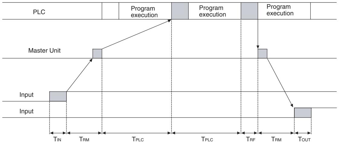
flowchart
graph TD
    A["Input"] --> B["Master Unit"]
    B --> C["Program execution"]
    C --> D["TIN"]
    D --> E["TRM"]
    E --> F["TPLC"]
    F --> G["TPLC"]
    G --> H["TRF"]
    H --> I["TRM"]
    I --> J["TOUT"]
    J --> K["Output"]
T_IN : ON/OFF delay time of the input slave (0 used as minimum value)
T_OUT : ON/OFF delay time of the output slave (0 used as minimum value)
T_RM : Communications time for entire network
T_PLC : Cycle time of PLC
T_RF : DeviceNet Unit refresh time at PLC
Note Refer to the operation manuals for the slaves for the input slave ON/OFF delay times and the output slave ON/OFF delay times. Refer to 6-1-2 Communications Cycle time and Refresh Processing Time and to the operation manual for the PLC for the PLC cycle time.
The maximum I/O refresh time can be calculated as follows:
$$ T _ {M A X} = T _ {I N} + 2 \times T _ {R M} + 2 \times T _ {P L C} + T _ {R F} + T _ {O U T} $$
6-1-2 Communications Cycle time and Refresh Processing Time
This section describes the communications cycle time and refresh processing time, which are required to calculate various processing times for DeviceNet.
Communications Cycle Time
The communications cycle time is the time from the completion of a slave's I/O communications processing until I/O communications with the same slave are processed again. The communications cycle time is the maximum communications cycle time T_IN + T_OUT .
The equations used to calculate the communications cycle time are described here.
Communications Cycle Time Equations
Total communications cycle time = IN communications cycle time + OUT communications cycle time.
■ IN Communications Cycle Time
IN communications cycle time = (39 ms + 8 ms × number of allocated data) + (6 ms × total allocated words in IN Areas 1 and 2)
■ OUT Communications Cycle Time
OUT communications cycle time = (29 ms + 27 ms x number of allocated data) + (7 ms × total allocated words in OUT Areas 1 and 2)
Refresh Processing Time
The refresh processing time is the time required for the CPU Unit of the PLC and the DeviceNet Master Unit to pass I/O information back and forth. The cycle time of the PLC is affected as described below when a DeviceNet Unit is mounted.
Note
Refer to the operation manuals for the PLCs for details on the refresh processing time and the PLC's cycle time.
CS/CJ-series, C200HX/HG/HE (-Z), and C200HS PLCs
The following times for I/O refreshing are added to the cycle time of the PLC when a Master Unit is mounted.
| Item | Processing time |
| I/O refresh | DeviceNet Unit I/O Refresh ProcessingCS/CJ-series or C200HX/HG/HE (-Z) PLCs1.72 + 0.022 x number of allocated words (see note) msC200HS PLCs2.27 + 0.077 x number of allocated words (see note) ms |
Note The number of allocated words is the total number of I/O area words allocated to all of the slaves. Any unused areas within the allocations must be included. For example, if only node address 1 with a 1-word input and node address 5 with a 1-word input are connected, the total number of words would be 5. When message communications are performed, the number of words required for message communications would have to be added to the above total number of words during the cycles in which message communications are processed.
6-1-3 Networks with More Than One Master
The communications cycle time, T_RM , when there is more than one master in the same network is described in this section. Here, a network with two masters is used as an example.
First, separate the network into two groups, slaves that perform remote I/O communications with master A and those that perform remote I/O communications with master B.
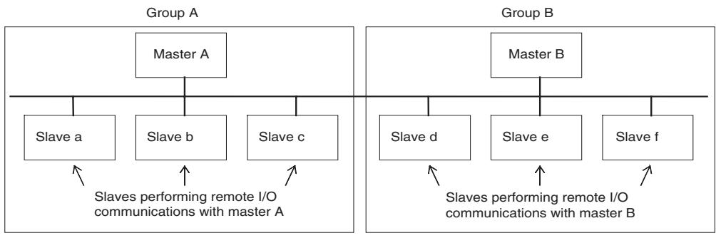
flowchart
graph TD
    subgraph Group_A
        A1["Master A"] --> A2["Slave a"]
        A1 --> A3["Slave b"]
        A1 --> A4["Slave c"]
        A2 -->|Slaves performing remote I/O communications with master A| B1
    end
    subgraph Group_B
        B1["Master B"] --> B2["Slave d"]
        B1 --> B3["Slave e"]
        B1 --> B4["Slave f"]
        B2 -->|Slaves performing remote I/O communications with master B| C1
    end
Note
Although for convenience, the slave are positioned in groups with the masters, in the actual network, the physical positions of the slaves will not necessarily be related to the master with which they communicate.
Next, calculate the communications cycle time for each group referring to 6-1-2 Communications Cycle time and Refresh Processing Time.
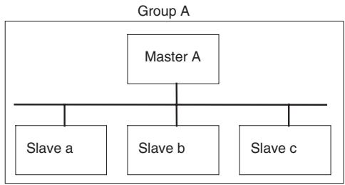
flowchart
graph TD
    A["Master A"] --> B["Slave a"]
    A --> C["Slave b"]
    A --> D["Slave c"]
Group A communications cycle time: T_RM-A
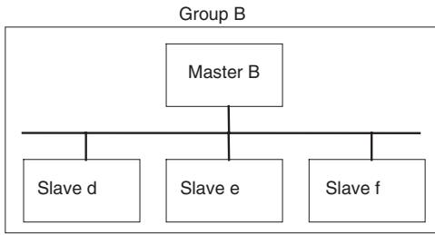
flowchart
graph TD
    A["Master B"] --> B["Slave d"]
    A --> C["Slave e"]
    A --> D["Slave f"]
Group A communications cycle time: T_RM-B
The communications cycle time for the overall network when there are two masters will be as follows:
$$ T _ {R M} = T _ {R M - A} + T _ {R M - B} $$
Although this example uses a network with only two masters, the same method can be used for any number of masters. Simply divide the network up according to remote I/O communications groups and then add all of the communications cycle times for the individual groups to calculate the communications cycle time for the overall network.
System Startup Time
This section describes the system startup time for a Network, assuming that the scan list is enabled and that remote I/O communications are set to start automatically at startup. The system startup time is the delay from the time that the Master Unit is turned ON or restarted until the time remote I/O communications begin.
The system startup time when the Master Unit is set to start up immediately after power supplies of all the slaves are turned ON is different from when the Master Unit is restarted while communications are in progress. The startup times are shown in the following table.
| Condition | Slave's indicator status | System startup time |
| The master is started immediately after slave startup. | NS indicator is OFF or flashing green. | 6 s |
| The master only is restarted. | NS indicator is flashing red while the master is OFF. | 8 s |
| The slaves only are restarted. | --- | 10 s |
Sample Program
The times described above are required for the DeviceNet system to start. The sample program in this section shows how to use the Master Slave Status to skip slave I/O processing until remote I/O communications have started.
Note
Refer to the operation manual for the Master Unit for information on the Master Status Area.
The following conditions apply to this sample program.
PLC: CS1 Series
Master Unit's unit number: 00
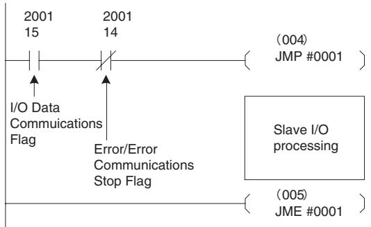
flowchart
graph TD
    A["2001 15"] --> B["I/O Data Communications Flag"]
    C["2001 14"] --> D["Error/Error Communications Stop Flag"]
    E["(004) JMP #0001"] --> F["Slave I/O processing"]
    G["(005) JME #0001"] --> H["Slave I/O processing"]
6-2 Message Communications Performance
6-2-1 Message Communications Time
The message communications time is the time required from when the Master Unit starts to send a message on the network until the entire message has been sent when a message is being sent from one node to another. The message will consist of data for a SEND or RECV instruction and a FINS command for an IOWR or CMND instruction.
Note If another message is sent before the message communications time elapses or is a message is received from another node before the message communications time elapses, the response message being sent or the message being received may be corrupted. When performing message communications it is thus necessary to allow the message communications time to elapse before performing message communications again using SEND, RECV, CMND, or IOWR instructions and to allow the message communications time to elapse between sending messages to the same node. If a send or receive message is corrupted, a record will be stored in the error log in the Master Unit. Use a FINS command to read the error record or use the Configurator to monitor the error log.
The message communications time can be estimated using the following equation:
Message communications time = Communications cycle time x {(number of message bytes + 15) ÷ 6 + 1}
The number of message bytes in the number of bytes after the FINS command code. The communications cycle time will depend on whether remote I/O communications is being used and can be calculated as described next.
Only Message Communications (Remote I/O Communications Stopped)
Communications cycle time = 2 (see note) + 0.11 x TB + 0.6 ms
TB depends on the baud range as follows:
500 KB/s: 2, 250 KB/s: 4, 125 KB/s: 8
Note The communications cycle time when remote I/O communications are stopped is 2 ms.
Message Communications and Remote I/O Communications
Communications cycle time = (communications cycle time for only remote I/O communications + 0.11 x TB + 0.6 ms
TB depends on the baud range as follows:
500 KB/s: 2, 250 KB/s: 4, 125 KB/s: 8
Note
The above calculations for the message communications times are only for use as guidelines. They do not produce maximum values. The message communications time depends on the frequency of messages, the load on the remote node, the communications cycle time, etc. If network traffic is concentrated on one Master Unit, long times will be required that those produced by the above calculations. Be sure to consider this when designing the system.
SECTION 7
Troubleshooting and Maintenance
This section describes error processing, periodic maintenance operations, and troubleshooting procedures needed to keep the DeviceNet Network operating properly. Details on resetting replaced Controllers are also provided. Read through the error processing procedures in both this manual and the operation manual for the DeviceNet master being used before operation so that operating errors can be identified and corrected more quickly.
7-1 Indicators and Error Processing 7-2
7-2 Maintenance 7-3
7-2-1 Cleaning 7-3
7-2-2 Inspection 7-3
7-2-3 Replacing Controllers.... 7-4
7-1 Indicators and Error Processing
The following table lists the indicator status when errors occur, the probable causes and processing.
| Indicator status | Probable cause | Remedy |
| MS: OFFNS: OFF | The power is not being supplied to the Controller. | Supply communications power from the DeviceNet connector. |
| The power voltage is not within the permitted range. | Use a power supply voltage within the permitted range. | |
| The Controller is faulty. | Replace the Controller. | |
| MS: Flashing redNS: No change | A checksum error has occurred in the parameters registered in EEPROM. | Repairs are required if this error persists even if the parameters are reset. Contact your nearest OMRON representative. |
| A EEPROM hardware error has occurred. | ||
| MS: ON redNS: OFF | The Digital Controller is faulty | Repairs are required. Contact your nearest OMRON representative. |
| MS: ON greenNS: Flashing green | Waiting to connect to DeviceNet communications. | Check the following items and restart the Controller.Are lengths of cables (trunk and branch lines) correct?Are cables short-circuited, broken, or loose?Are cables wired correctly?Is terminating resistance connected to both ends of the trunk line only?Is noise interference excessive?Is the power to the master ON? |
| The Digital Controller is faulty. | Repairs are required. Contact your nearest OMRON representative. | |
| MS: ON greenNS: ON red | The DeviceNet is in Bus OFF status. | Check the following items and restart the Controller.Are lengths of cables (trunk and branch lines) correct?Are cables short-circuited, broken, or loose?Is terminating resistance connected to both ends of the trunk line only?Is noise interference excessive? |
| Node addresses duplicated. | Reset node addresses correctly. | |
| The Controller is faulty. | Repairs are required. Contact your nearest OMRON representative. | |
| MS: ON greenNS: Flashing red | A communications time-out has occurred. | Check the following items and restart the Controller.Are lengths of cables (trunk and branch lines) correct?Are cables short-circuited, broken, or loose?Is terminating resistance connected to both ends of the trunk line only?Is noise interference excessive? |
| The Digital Controller is faulty. | Repairs are required. Contact your nearest OMRON representative. |
7-2 Maintenance
This section describes the routine cleaning and inspection recommended as regular maintenance. Handling methods when replacing Controllers are also explained here.
7-2-1 Cleaning
Clean the Controllers regularly as described below in order to keep the Network in its optimal operating condition.
- Wipe the Controller with a dry, soft cloth for regular cleaning.
- When dust or dirt cannot be removed with a dry cloth, dampen the cloth with a neutral cleanser (2%), wring out the cloth, and wipe the Controller.
- Smudges may remain on the Controller from gum, vinyl, or tape that was left on for a long time. Remove these smudges when cleaning.
Note Never use volatile solvents, such as paint thinner or benzene, or chemical wipes to clean the Controller. These substances may damage the surface of the Controller.
7-2-2 Inspection
Inspect the system periodically to keep it in its optimal operating condition.
In general, inspect the system once every 6 to 12 months, but inspect more frequently if the system is used in high-temperature, humid, or dusty conditions.
Inspection Equipment
Prepare the following equipment before inspecting the system.
Equipment Required for Regular Inspection
A flat-blade and a Phillips screwdriver, a screwdriver for connecting communications connectors, a tester (or a digital voltmeter), industrial alcohol, and a clean cloth are required for routine inspection.
Other Equipment that May Be Required
A synchroscope, oscilloscope, thermometer, or hygrometer may be required.
Inspection Procedure
Check the items in the following table and correct any condition that is below standard by adjusting the Controller or improving the environmental conditions.
| Inspection item | Details | Standard | Equipment |
| Environmental conditions | Are ambient and cabinet temperatures correct? | -10 to +55°C | Thermometer |
| Are ambient and cabinet humidity cor-rect? | 25% to 85% | Hygrometer | |
| Has dust or dirt accumulated? | No dust or dirt | Visual inspection | |
| Installation conditions | Are the connectors of the communica-tions cables fully inserted? | No looseness | Phillips screwdriver |
| Are the external wiring screws tight? | No looseness | Phillips screwdriver | |
| Are the connecting cables undamaged? | No external damage | Visual inspection |
7-2-3 Replacing Controllers
The Network consists of the DeviceNet Master Unit and Slave Units. The entire network is affected when a Unit is faulty, so a faulty Unit must be repaired or replaced quickly. We recommend having spare Units available to restore Network operation as quickly as possible.
Precautions
Observe the following precautions when replacing a faulty Controller.
- After replacement make sure that there are no errors with the new Controller.
- When a Controller is being returned for repair, attach a sheet of paper detailing the problem and return the Controller to your OMRON dealer.
- If there is a faulty contact, try wiping the contact with a clean, lint-free cloth dampened with alcohol.
Note Before replacing a Controller, always stop Network communications and turn OFF the power to all the nodes in the Network.
Appendix A
Detailed DeviceNet Specifications
Data Size and Connection Types
If the connection type can be set when another company's configurator is being used, select a connection supported by the DeviceNet Communications Unit.
The following table shows the connection types and data sizes for OMRON DeviceNet Communications Units.
| Model | Supported connections | Data size (bytes) | ||||
| Poll | Bit strobe | Change of state (COS) | Cyclic | IN | OUT | |
| E5AR/ER-DRT | Yes | Yes | Yes | Yes | 0 to 200(See note.) | 0 to 200(See note.) |
Note The size of the IN/OUT Areas depends on the setting.
DeviceNet I/O communications support the following types of connections.
| Connection type | Details | Remarks |
| Poll | Used to exchange data between the master and individual slaves by sending and receiving commands and responses. (Output data is allocated for commands and input data is allocated for responses). | --- |
| Bit strobe | Used to broadcast commands from the master and receive input responses from multiple slaves. | By using one command only, the communications cycle time is short, but bit strobe connections can be used only with slaves with 8 or less input points. |
| Change of state (COS) | Normally, input and output data are sent by master and slaves at regular cycles, but with a COS connection, data is sent to the master or slave when the master or slave data changes. | By setting a long cycle interval, the Network will not be loaded with communications for minor data changes, thereby improving the overall efficiency of the Network. |
| Cyclic | Masters and slaves send output or input data at regular cycles. |
Device Profiles
The following device profiles contain more detailed DeviceNet specifications for DeviceNet communications if more information needs to be registered in the scan list.
| General data | Compatible DeviceNet Specifications | Volume I - Release 2.0Volume II - Release 2.0 | |
| Vendor name | OMRON Corporation | Vendor ID = 47 | |
| Device profile name | Slaves: Generic Device | Profile number = 0 | |
| Manufacturer catalog number | H124 | ||
| Manufacturer revision | 1.01 | ||
| Physical conformance data | Network current consumption | 50 mA max. | |
| Connector type | Open plug | ||
| Physical layer insulation | No | ||
| Supported indicators | Module, Network | ||
| MAC ID setting | Software switch | ||
| Default MAC ID | 1 | ||
| Baud rate setting | Automatic recognition | ||
| Supported baud rates | 125 kbps, 250 kbps, and 500 kbps | ||
| Communications data | Predefined Master/Slave connection set | Group 2 only server | |
| Dynamic connection support (UCMM) | No | ||
| Explicit message fragmentation support | Yes | ||
Appendix B
Mounted Objects
Identity Object (0x01)
| Object class | Attribute | Not supported |
| Service | Not supported |
| Object instance | Attribute | ID | Contents | Get (read) | Set (write) | Value |
| 1 | Vendor | Yes | No | 47 | ||
| 2 | Device type | Yes | No | 0 | ||
| 3 | Product code | Yes | No | 334 | ||
| 4 | Revision | Yes | No | 1.1 | ||
| 5 | Status (bits supported) | Yes | No | Bit 00 only | ||
| 6 | Serial number | Yes | No | Unique for each Unit | ||
| 7 | Product name | Yes | No | E5R-DRT | ||
| 8 | State | No | No | |||
| Service | DeviceNet service | Parameter option | ||||
| 05 | Reset | No | ||||
| 0E | Get_Attribute_Single | No | ||||
Message Router Object (0x02)
| Object class | Attribute | Not supported |
| Service | Not supported | |
| Object instance | Attribute | Not supported |
| Service | Not supported | |
| Vendor specification addition | None |
DeviceNet Object (0x03)
| Object class | Attribute | Not supported |
| Service | Not supported |
| Object instance | Attribute | ID | Contents | Get (read) | Set (write) | Value |
| 1 | MAC ID | No | No | |||
| 2 | Baud rate | Yes | No | |||
| 3 | BOI | Yes | No | 00 (hexadecimal) | ||
| 4 | Bus OFF counter | No | No | |||
| 5 | Allocation information | Yes | No | |||
| Service | DeviceNet service | Parameter option | ||||
| 0E | Get_Attribute_Single | None | ||||
| 4B | Allocate_Master/Slave_Connection_Set | None | ||||
| 4C | Release_Master/Slave_Connection_Set | None | ||||
Assembly Object (0x04)
| Object class | Attribute | Not supported |
| Service | Not supported |
| Object instance100: IN Area 1101: IN Area 2110: OUT Area 1 | Attribute | ID | Contents | Get (read) | Set (write) | Value |
| 1 | Number of members in list | No | No | |||
| 2 | Member list | No | No | |||
| 3 | Data | Yes | No | |||
| Service | DeviceNet service | Parameter option | ||||
| 0E | Get_Attribute_Single | None | ||||
Connection Object (0x05)
| Object class | Attribute | Not supported |
| Service | Not supported | |
| Maximum number of active connections | 1 |
| Object instance 1 | Section | Information | Maximum number of instances | |||
| Instance type | Explicit Message | 1 | ||||
| Production trigger | Cyclic | |||||
| Transport type | Server | |||||
| Transport class | 3 | |||||
| Attribute | ID | Contents | Get (read) | Set (write) | Value | |
| 1 | State | Yes | No | |||
| 2 | Instance type | Yes | No | 00 (hexadecimal) | ||
| 3 | Transport class trigger | Yes | No | 83 (hexadecimal) | ||
| 4 | Produced connection ID | Yes | No | |||
| 5 | Consumed connection ID | Yes | No | |||
| 6 | Initial comm. characteristics | Yes | No | 21 (hexadecimal) | ||
| 7 | Produced connection size | Yes | No | 0176 (hexadecimal) | ||
| 8 | Consumed connection size | Yes | No | |||
| 9 | Expected packet rate | Yes | Yes | 01 (hexadecimal) | ||
| 12 | Watchdog time-out action | Yes | No | 01 (hexadecimal) | ||
| 13 | Produced connection path length | Yes | No | 00 (hexadecimal) | ||
| 14 | Produced connection path | Yes | No | |||
| 15 | Consumed connection path | Yes | No | 00 (hexadecimal) | ||
| Service | DeviceNet service | Parameter option | ||||
| 05 | Reset | None | ||||
| 0E | Get_Attribute_Single | None | ||||
| 10 | Set_Attribute_Single | None | ||||
| Object instance 2 | Section | Information | Maximum number of instances | |||
| Instance type | Polled I/O | 1 | ||||
| Production trigger | Cyclic | |||||
| Transport type | Server | |||||
| Transport class | 2 | |||||
| Attribute | ID | Contents | Get (read) | Set (write) | Value | |
| 1 | State | Yes | No | |||
| 2 | Instance type | Yes | No | 01 (hexadecimal) | ||
| 3 | Transport class trigger | Yes | No | 82 (hexadecimal) | ||
| 4 | Produced connection ID | Yes | No | |||
| 5 | Consumed connection ID | Yes | No | |||
| 6 | Initial comm. characteristics | Yes | No | 01 (hexadecimal) | ||
| 7 | Produced connection size | Yes | No | |||
| 8 | Consumed connection size | Yes | No | |||
| 9 | Expected packet rate | Yes | Yes | |||
| 12 | Watchdog time-out action | Yes | No | 00 (hexadecimal) | ||
| 13 | Produced connection path length | Yes | No | 06 (hexadecimal) | ||
| 14 | Produced connection path | Yes | No | See note 1. | ||
| 15 | Consumed connection path length | Yes | No | 06 (hexadecimal) | ||
| 16 | Consumed connection path | Yes | No | See note 2. | ||
| 17 | Production inhibit time | Yes | No | 0000 (hexadecimal) | ||
| Service | DeviceNet service | Parameter option | ||||
| 05 | Reset | None | ||||
| 0E | Get_Attribute_Single | None | ||||
| 10 | Set_Attribute_Single | None | ||||
- Produced Connection Paths
IN Area 1: 20_04_24_64_30_03
IN Area 2: 20_04_24_65_30_03
- Consumed Connection Paths
OUT Area: 20_04_24_6E_30_03
| Object instance 4 | Section | Information | Maximum number of instances | |||
| Instance type | COS Cyclic | 1 | ||||
| Production trigger | Cyclic | |||||
| Transport type | Server | |||||
| Transport class | 2 | |||||
| Attribute | ID | Contents | Get (read) | Set (write) | Value | |
| 1 | State | Yes | No | |||
| 2 | Instance type | Yes | No | 01 (hexadecimal) | ||
| 3 | Transport class trigger | Yes | No | 12 (hexadecimal) | ||
| 4 | Produced connection ID | Yes | No | |||
| 5 | Consumed connection ID | Yes | No | |||
| 6 | Initial comm. characteristics | Yes | No | 01 (hexadecimal) | ||
| 7 | Produced connection size | Yes | No | |||
| 8 | Consumed connection size | Yes | No | 0800 (hexadecimal) | ||
| 9 | Expected packet rate | Yes | Yes | |||
| 12 | Watchdog time-out action | Yes | No | 00 (hexadecimal) | ||
| 13 | Produced connection path length | Yes | No | 06 (hexadecimal) | ||
| 14 | Produced connection path | Yes | No | See note. | ||
| 15 | Consumed connection path length | Yes | No | 04 (hexadecimal) | ||
| 16 | Consumed connection path | Yes | No | 202B2401 | ||
| 17 | Production inhibit time | Yes | Yes | 0000 (hexadecimal) | ||
| Service | DeviceNet service | Parameter option | ||||
| 05 | Reset | None | ||||
| 0E | Get_Attribute_Single | None | ||||
| 10 | Set_Attribute_Single | None | ||||
Note Produced Connection Paths
IN Area 1: 20_04_24_64_30_03
IN Area 2: 20_04_24_65_30_03
Appendix C
DeviceNet Connection Hardware
DeviceNet Communications Cables
| Model | Specifications | Manufacturer |
| DCA1-5C10 | Thin Cable: 5 wires, 100 m | OMRON |
| DVN24-10G | Thin Cable: 5 wires, 10 m | Nihon Wire & Cable (See note 1.) |
| DVN24-30G | Thin Cable: 5 wires, 30 m | Nihon Wire & Cable (See note 1.) |
| DVN24-50G | Thin Cable: 5 wires, 50 m | Nihon Wire & Cable (See note 1.) |
| DVN24-100G | Thin Cable: 5 wires, 100 m | Nihon Wire & Cable (See note 1.) |
| DVN24-300G | Thin Cable: 5 wires, 300 m | Nihon Wire & Cable (See note 1.) |
| DVN24-500G | Thin Cable: 5 wires, 500 m | Nihon Wire & Cable (See note 1.) |
| 1485C-P1-C150 | Thin Cable: 5 wires, 150 m | Allen-Bradley (See note 2.) |
| DCA1-5CN□□W1 | Cable with shielded micro-size (M12) connectors on both ends (female socket and male plug)Cable length: 0.5 m, 1 m, 2 m, 3 m, 5 m, and 10 m | OMRON |
| DCA1-5CN□□F1 | Cable with shielded micro-size (M12) connector (female socket) on one endCable length: 0.5 m, 1 m, 2 m, 3 m, 5 m, and 10 m | OMRON |
| DCA1-5CN□□H1 | Cable with shielded micro-size (M12) connector (male plug) on one endCable length: 0.5 m, 1 m, 2 m, 3 m, 5 m, and 10 m | OMRON |
| DCA1-5CN□□W5 | Cable with shielded connector on both ends (male plug on mini-size end, female socket on micro-size end)Cable length: 1 m, 2 m, 5 m, and 10 m | OMRON |
Note 1. The product specifications for these cables are identical to the OMRON cable specifications.
2. The cables made by Allen-Bradley are stiffer than the cables made by OMRON and Nihon Wire & Cable Company Ltd., so do not bend the Allen-Bradley cables as much as the others.
Other DeviceNet communications cables are available from the following manufacturers. For details, refer to the product catalogs on the ODVA web site (http://www.odva.astem.or.jp/) or contact the manufacturer directly.
DeviceNet Connector
| Model | Specifications | Manufacturer |
| FCK2.5/5-STF-5.08AU | For node connectionScrewless type, includes connector set screws | PHOENIX CONTACT |
Crimp Terminals for DeviceNet Communications Cables
| Model | Crimper | Remarks | Manufacturer |
| AI series: AI-0.5-6WH for Thin Cable (product code: 3200687) | ZA3 | For single-wire insertion | PHOENIX CONTACT |
| AI series: AI-0.25-6BU for Thin Cable (product code: 3201291) | UD6 (product code: 1204436) | For two-wire insertion (multi-drop wiring) |
Terminating Resistors for DeviceNet Network
| Model | Specifications | Manufacturer |
| DRS1-T | Terminal-block Terminating Resistor, 121 Ω ±1% 1/4 W | OMRON |
| DRS2-1 | Shielded Terminating Resistor (male plug), micro-size (M12) | |
| DRS2-2 | Shielded Terminating Resistor (female socket), micro-size (M12) | |
| DRS3-1 | Shielded Terminating Resistor (male plug), mini-size |
A Terminating Resistor can also be connected to a T-branch Tap or a one-branch Power Supply Tap.
T-branch Taps
One-branch Taps
| Model | Specifications | Manufacturer |
| DCN1-1C | Includes three XW4B-05C1-H1-D parallel connectors with screws (When used on a trunk line, one branch line can be connected.) Connector insertion direction: Horizontal A Terminating Resistor (included as standard) can be connected. | OMRON |
| DCN1-2C | Includes three XW4B-05C1-H1-D parallel connectors with screws (When used on a trunk line, one branch line can be connected.) Connector insertion direction: Vertical A Terminating Resistor (included as standard) can be connected. | OMRON |
| DCN1-2R | Includes three XW4B-05C1-VIR-D orthogonal connectors with screws (When used on a trunk line, one branch line can be connected.) Connector insertion direction: Vertical A Terminating Resistor (included as standard) can be connected. | OMRON |
Three-branch Taps
| Model | Specifications | Manufacturer |
| DCN1-3C | Includes five XW4B-05C1-H1-D parallel connectors with screws(When used on a trunk line, three branch lines can be connected.)Connector insertion direction: HorizontalA Terminating Resistor (included as standard) can be connected. | OMRON |
| DCN1-4C | Includes five XW4B-05C1-H1-D parallel connectors with screws(When used on a trunk line, three branch lines can be connected.)Connector insertion direction: VerticalA Terminating Resistor (included as standard) can be connected. | OMRON |
| DCN1-4R | Includes five XW4B-05C1-VIR-D orthogonal connectors with screws(When used on a trunk line, three branch lines can be connected.)Connector insertion direction: VerticalA Terminating Resistor (included as standard) can be connected. | OMRON |
Shielded T-branch Connectors
| Model | Specifications | Manufacturer |
| DCN2-1 | One-branch shielded T-branch connectors, three micro-size (M12) connectors | OMRON |
| DCN3-11 | One-branch shielded T-branch connectors, three mini-size connectors | |
| DCN3-12 | One-branch shielded T-branch connectors, two mini-size connectors and one micro-size (M12) connector |
One-branch Power Supply Tap
| Model | Specifications | Manufacturer |
| DCN-1P | One-branch tap for power supply. Use this tap when connecting a communications power supply.Includes two XW4B-05C1-H1-D parallel connectors with screws and two fuses as standard.A Terminating Resistor (included as standard) can be connected. | OMRON |
Glossary
The following table provides a list of commonly used DeviceNet terms.
| Term | Explanation |
| Bus OFF | Indicates that the error rate in the network is extremely high. Errors are detected when a fixed threshold is exceeded by the internal error counter. (the internal error counter is cleared when the Master Unit is started or restarted.) |
| CAN | CAN is short for Controller Area Network. It is a communications protocol developed as a LAN for use in automobiles. DeviceNet employs CAN technology. |
| Configurator | A device for setting the system settings. The Configurator can read ID information, read and write parameters, and display the network configuration.OMRON's DeviceNet Configurator is designed for use with an OMRON Master Unit. |
| Consumed Connection Size | Indicates the data size (byte length) received via the connection. |
| ODVA | ODVA is short for Open DeviceNet Vendor Association, Inc. It is a non-profit organization formed by machine vendors with the aim to administer and popularize the DeviceNet specification. |
| Produced Connection Size | Indicates the data size (byte length) sent via the connection. |
| Connection | This is a logical communication channel for facilitating communications between nodes. Communications are maintained and managed between the master and slaves. |
| Device Profile | Standardizes the configuration and behavior (the smallest data configuration and operation that must be supported by the device) of devices of the same type (equipment, etc.). Provides mutual exchangeability between devices of the same type. Also known as a device model. Devices for which device profiles are currently being investigated include sensors, valves, display units, and encoders. |
| Master/Slave | A node can be either a master, which collects and distributes data, or a slave, which outputs and inputs data according to the instructions received from the master. OMRON's DeviceNet products are already provided with either master or slave functions in a predefined master/slave connection set. |
Index
A
accumulated ON (RUN) time monitor, 2-5
AT cancel, 4-12
AT execute, 4-12
auto mode, 4-12
auto/manual, 4-12
auxiliary outputs (terminals), 3-12
B
bank selection, 4-12
bit strobe, A-1
C
cables
communications cables models, C-1
change of state (COS), A-1
cleaning, 7-3
command block, 5-3, 5-5, 5-6
communications
cables, C-1
connection example, 1-2
cycle time, 6-3
distance, 1-5
error operation, 2-5
performance, xvii, 6-1
specifications, 1-5
Communications Power Voltage Monitor Error Flag, 4-11
CompoWay/F ASCII commands, 5-3, 5-5
CompoWay/F binary commands, 5-3, 5-5
CompoWay/F commands, 5-4
Configurator
operations, 2-3
connections, 2-2
hardware, C-1
connectors
attaching, 3-16
models, C-1
control outputs (terminals), 3-11
crimp terminals, 3-16, C-2
models, C-2
current consumption, 1-5
cyclic, A-1
D
device profiles, A-2
DeviceNet communications cables, C-1
preparing, 3-15
wiring, 3-15
DeviceNet communications connector, 2-2
DeviceNet Communications Unit connector, 3-16
DeviceNet Connector, C-1
E
EC Directives, xiii
conformance, xiii
EMC Directives, xiii
error codes, 5-4
event inputs (terminals), 3-13
explicit messages, 1-3, 5-2
basic message format, 5-3
error codes, 5-4
General Status Read, 5-7
Maintenance Counter Save, 5-7
sending, 5-6
Set Value for Unit Conduction Time or Total RUN Time, 5-7
specific to DeviceNet, 5-6
types, 5-2
Unit Conduction Time or Total RUN Time Read, 5-8
external dimensions, 3-2
G
general status, 4-3, 4-11
I
I/O allocations, 4-2
area size, 4-3
data size, 4-3, 4-5
default values, 4-4
parameters, 4-3
settings, 4-5
I/O response time, 6-2
IN Area, 4-3
indicators, 3-3, 7-2
troubleshooting, 7-2
initialize setting, 4-12
inputs (terminals), 3-10
inspection, 7-3
installation, 3-4
instance ID, 5-8
insulation blocks, 3-18
L
latch reset, 4-12
M
maintenance, xvii, 7-1, 7-3
replacing Units, 7-4
manual mode, 4-12
message communications time, 6-6
module status (MS indicator), 3-3
N
network power monitor, 2-4
network status (NS indicator), 3-3
networks with multiple masters, 6-4
0
One-branch Power Supply Taps, C-3
One-branch Taps, C-2
operation commands, 4-12
OUT Area, 4-3
Output Enable Bits, 4-4, 4-11
P
panel cutout dimensions, 3-4
part names, 3-2
poll, A-1
potentiometer inputs (terminals), 3-13
power supply (terminals), 3-10
precautions
wiring, 3-9
programming
samples, 4-13, 4-16
protect level
move to, 4-12
pulling out the Controller, 3-5
R
refresh processing time, 6-3, 6-4
remote I/O communications, 1-2, 1-3, 4-1
performance, 6-2
removing Controllers, 3-5
replacing Controllers, 7-4
replacing Units, 7-4
response block, 5-3, 5-5, 5-6
RUN/STOP, 4-12
S
Setting Area 1
move to, 4-12
setup procedure, 2-2
Shielded T-branch Connectors, C-3
slaves
maximum number, 1-5
software reset, 4-12
SP mode, 4-12
specifications
communications, 1-5
DeviceNet, A-1
general, 1-5
startup time, 6-5
status, 4-3, 4-9
strobe, 4-12, 4-14
supply voltage, 1-5
system startup time, 6-5
T
T-branch Taps, C-2
terminal arrangement, 3-6
Terminating Resistors, C-2
Three-branch Taps, C-2
transfer outputs (terminals), 3-11
troubleshooting, 1-xvii, 7-1
U
Unit Maintenance Flag, 4-11
W
wiring, 3-10
precautions, 3-9
write mode, 4-12
Revision History
A manual revision code appears as a suffix to the catalog number on the front cover of the manual.
Cat. No. H124-E1-01
The following table outlines the changes made to the manual during each revision. Page numbers refer to the previous version.
| Revision code | Date | Revised content |
| 1 | February 2004 | Original production |
- OMRON
- 11-01, UE Square,
- E5AR/ER
- Digital Controller
- DeviceNet
- Communications
- DeviceNet Communications
- Notice:
- Visual Aids
- Trademarks
- © OMRON, 2004
- Warranty and Limitations of Liability
- WARRANTY
- LIMITATIONS OF LIABILITY
- Application Considerations
- SUITABILITY FOR USE
- PROGRAMMABLE PRODUCTS
- Precautions for Safe Use
- ● Definition of Safety Notices and Information
- Symbols
- WARNING
- CAUTION
- EC Directives
- Concepts
- EMC Directives
- Conformance to EC Directives
- 1,2,3...
- TABLE OF CONTENTS
- SECTION 1
- Overview 1-1
- SECTION 2
- Operating Procedures.... 2-1
- SECTION 3
- Parts, Installation, and Wiring 3-1
- SECTION 4
- Remote I/O Communications 4-1
- SECTION 5
- Explicit Message Communications .... 5-1
- SECTION 6
- Communications Performance 6-1
- SECTION 7
- Troubleshooting and Maintenance 7-1
- Appendices
- About this Manual:
- Related Manuals:
- SECTION 1 Overview
- 1-1 Features
- 1-1-1 Outline
- 1-1-2 Communications Connection Example
- 1-1-3 Using DeviceNet
- Explicit Message Communications
- Automatically Detects Baud Rate
- 1-1-4 Default Communications Settings
- 1-1-5 Data Allocation
- 1-1-6 Remote I/O Communications
- 1-2 Specifications
- 1-2-1 DeviceNet Communications Specifications
- Note
- 1-2-2 DeviceNet General Specifications
- Operating Procedures
- 2-1 Introduction
- 2-1-2 Startup Procedure
- 2-1-3 Setting Node Addresses
- Setting Operation
- Setting Parameters
- 2-2 Functions Supported Only by the E5AR/ER-DRT
- 2-2-1 Network Power Monitor Function
- 2-2-2 Accumulated ON (RUN) Time Monitor Function
- 2-2-3 Operation for Communications Errors
- Parts, Installation, and Wiring
- 3-1 Part Names and Functions
- 3-1-1 Part Names
- DeviceNet Communications Connector
- 3-1-2 External Dimensions
- 3-1-3 MS and NS Indicators
- Normal Indicator Display
- 3-1-4 Installation
- Panel Cutout Dimensions
- Installation Procedure
- Pulling Out the Controller
- 3-2 How to Use the Terminals
- 3-2-1 Connections
- 3-2-2 Precautions when Wiring
- 3-2-3 Wiring
- Power Supply (Terminals)
- Inputs (Terminals)
- Control Outputs or Transfer Outputs (Terminals)
- Auxiliary Outputs (Terminals)
- Potentiometer Inputs (Terminals)
- Event Inputs (Terminals)
- 3-3 DeviceNet Communications Cables Wiring
- 3-3-1 Preparing DeviceNet Communications Cables
- 3-3-2 Attaching the DeviceNet Communications Unit Connector
- 3-3-3 Insulation Blocks
- Remote I/O Communications
- 4-1 Overview
- 4-2 I/O Allocation
- 4-2-1 Allocation Area Size
- 4-2-2 Allocation Parameters
- E5AR/ER-DRT Operation Data and Setting Data
- Output Enable Bits
- 4-2-3 Allocation Default Values
- 4-2-4 Allocation Data Size (IN Data Size and OUT Data Size)
- 4-2-5 Allocation Settings
- E5□R Status
- 4-2-6 Input Data
- General Status (Setting: 2)
- 4-2-7 Output Data
- Output Enable Bits
- 4-2-8 Operation Commands
- 4-3 Ladder Programming Examples
- 4-3-1 RUN/STOP Sample Programming
- Operation
- 4-3-2 Change SP Sample Programming
- Outline
- Programming Example
- 5-1 Overview of Explicit Message Communications
- 5-1-1 Explicit Message Communications
- Reading/Writing E5AR/E5ER Variable Area Data and Sending Operation Commands
- Reading/Writing E5AR/E5ER-DRT Maintenance Information
- 5-1-2 Explicit Message Types
- Sending CompoWay/F Commands to the E5AR/E5ER-DRT (Embedded in Explicit Messages)
- ■ CompoWay/F Binary Commands
- ■ CompoWay/F ASCII Commands
- Sending Explicit Messages Specific to DeviceNet-compatible Digital Controllers
- 5-1-3 Explicit Messages Basic Format
- Command Block
- Destination Node Address
- Service Code, Class ID, Instance ID, Attribute ID
- Data
- Response Block
- Number of Bytes Received
- Source Node Address
- Service Code
- Error Code
- 5-2 Sending CompoWay/F Commands to the Digital Controller
- 5-2-1 CompoWay/F Binary Commands
- Normal Response
- 5-2-2 CompoWay/F ASCII Commands
- 5-3 Explicit Messages Specific to DeviceNet-compatible Digital Controllers
- Communications Performance
- 6-1 Remote I/O Communications Performance
- 6-1-1 I/O Response Time
- Minimum I/O Response Time
- Maximum I/O Response Time
- 6-1-2 Communications Cycle time and Refresh Processing Time
- Communications Cycle Time
- Communications Cycle Time Equations
- ■ IN Communications Cycle Time
- ■ OUT Communications Cycle Time
- Refresh Processing Time
- CS/CJ-series, C200HX/HG/HE (-Z), and C200HS PLCs
- 6-1-3 Networks with More Than One Master
- System Startup Time
- Sample Program
- 6-2 Message Communications Performance
- 6-2-1 Message Communications Time
- Message Communications and Remote I/O Communications
- Troubleshooting and Maintenance
- 7-1 Indicators and Error Processing
- 7-2 Maintenance
- 7-2-1 Cleaning
- 7-2-2 Inspection
- Inspection Equipment
- Equipment Required for Regular Inspection
- Other Equipment that May Be Required
- Inspection Procedure
- 7-2-3 Replacing Controllers
- Precautions
- Appendix A
- Detailed DeviceNet Specifications
- Data Size and Connection Types
- Device Profiles
- Appendix B
- Mounted Objects
- Appendix C
- DeviceNet Connection Hardware
- T-branch Taps
- Glossary
- Index
- A
- B
- C
- D
- E
- G
- I
- L
- M
- N
- 0
- P
- R
- S
- T
- U
- W
- Revision History
Marque : OMRON
Modèle : E5AR
Catégorie : Contrôleur de température