
E5 K-T - Contrôleur de température OMRON - Notice d'utilisation et mode d'emploi gratuit
Retrouvez gratuitement la notice de l'appareil E5 K-T OMRON au format PDF.


| Type de produit | Contrôleur de température programmable numérique |
| Marque | OMRON |
| Modèle | E5□K-T (E5AK-T, E5EK-T, E5CK-T) |
| Dimensions (mm) | E5AK-T : 96 x 96 ; E5EK-T : 96 x 48 ; E5CK-T : 58 x 58 |
| Alimentation | 100 à 240 VAC (50/60 Hz) ou 24 VAC/DC |
| Programmes | E5AK/E5EK : jusqu'à 8 motifs ; E5CK : jusqu'à 4 motifs |
| Pas par motif | 16 pas maximum |
| Précision | Échantillonnage 100 ms (entrée analogique) |
| Entrée | Thermocouple, thermomètre à résistance, signal analogique |
| Sorties de contrôle | Relais, impulsion (NPN/PNP), linéaire (4-20 mA, 0-20 mA, 0-10 V) |
| Alarmes | 2 alarmes (standard) |
| Communication série | RS-232C, RS-422, RS-485 (selon modèle) |
| Fonctions spéciales | Auto-tuning, contrôle proportionnel, mode manuel, hold, wait |
| Indice de protection | IP66/NEMA4 (face avant, usage intérieur) |
| Température ambiante | -10 °C à 55 °C (sans givre ni condensation) |
| Humidité ambiante | 35 % à 85 % sans condensation |
| Nettoyage | Utiliser de l'alcool standard ; éviter solvants ou diluants |
| Sécurité | Ne pas toucher les bornes sous tension ; respecter les tensions et charges nominales |
| Pièces détachées / accessoires | Unités de sortie (E53-*), unités option (E53-CK*), cache-bornes (E53-COV07) |
| Réparabilité | Structure modulaire ; ne pas démonter le boîtier |
| Normes | Conforme aux normes internationales CEM et sécurité (CE) |
FOIRE AUX QUESTIONS - E5 K-T OMRON
Questions des utilisateurs sur E5 K-T OMRON
0 question sur cet appareil. Repondez a celles que vous connaissez ou posez la votre.
Poser une nouvelle question sur cet appareil
Téléchargez la notice de votre Contrôleur de température au format PDF gratuitement ! Retrouvez votre notice E5 K-T - OMRON et reprennez votre appareil électronique en main. Sur cette page sont publiés tous les documents nécessaires à l'utilisation de votre appareil E5 K-T de la marque OMRON.
MODE D'EMPLOI E5 K-T OMRON
Digital Controller
E5□K-T
The E5□K-T Programmable Type Digital
Controllers Expand the Variety of E5□K
Digital Controllers and are Available in Three
Sizes (1/4, 1/8, and 1/16 DIN).
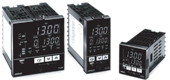

E5□K-T Series
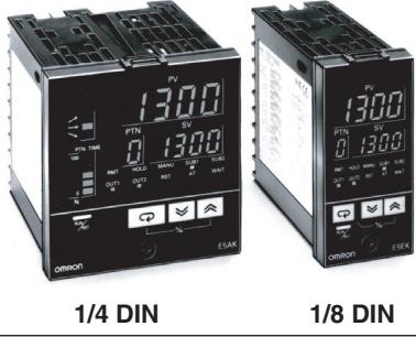
E5AK-T/E5EK-T
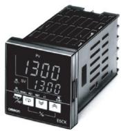
E5CK-T
1/16 DIN
Contents
Digital Controllers
E5AK-T/E5EK-T I-125
E5CK-T. I-127
■ Programming is as easy as following the steps below.
Program can be set in pattern 0 according to the following procedure.
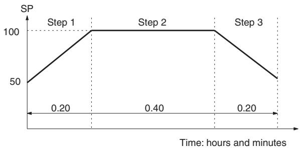
| Step No. | Target value | Time (hours.minutes) |
| 0 | 50 | 0.00 |
| 1 | 100 | 0.20 |
| 2 | 100 | 0.40 |
| 3 | 50 | 0.20 |
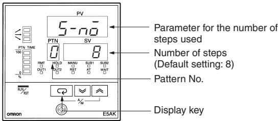
- Press the Display Key to shift to the display for the number of steps.
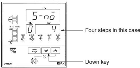
- Press the Down Key and set the number of steps.
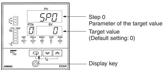
- Press the Display Key to shift to the display for the target value of step 0.
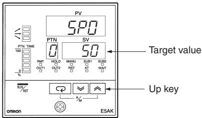
- Set the target value to "50."
- Press the Display Key to shift to the display for the time of step 0.
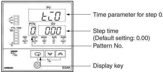
- Press the Display Key again with the step time set at 0 minutes, and the target value parameter for step 1 will be displayed.
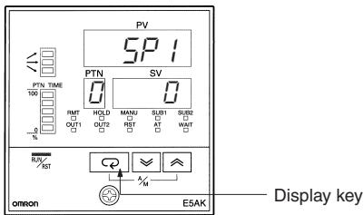
- Press the Up Key to increment to "100."
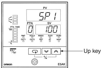
In the same manner, set the time for step 1, target value for step 2, time for step 2, etc.
When the target value and time settings are complete, press the Display Key.
Digital Controller
E5AK-T/E5EK-T
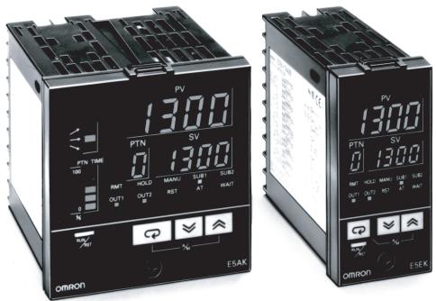
Advanced Programmable Digital Controllers Ideal for Worldwide Use
- Offers up to eight patterns of simple programming control (16 steps per pattern).
Modular structure, one-stock type
High-accuracy: 100-ms sampling (for analog input) - Conforms to international EMC and safety standards.
- IP66/HEMA4 (indoor use) front face
- Serial communications (RS-232C, RS-422 and RS-485) and transfer output (4 to 20 mA)
- Position-proportional control model
- Heating/cooling control
24VAC/DC types are also available.
C∈
Model Number Structure
■ Model Number Legend
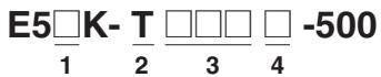
- Size
A: 96 × 96 ~mm
E: 96 × 48 ~mm
C: 58 × 58 ~mm
- Programmable type
T: Programmable type
Ordering Information
- Model
AA: Standard model
PRR: Position-proportional model
- Number of alarms
2: Two alarms
■ List of Models
| Description | Model | Specification |
| Base Unit | E5AK-TAA2 AC100-240 | Standard model |
| E5AK-TAA2-500 AC100-240 | Standard model with terminal cover | |
| E5AK-TAA2 AC/DC24 | Standard model | |
| E5AK-TAA2-500 AC/DC24 | Standard model with terminal cover | |
| E5AK-TPRR2 AC100-240 | Position-proportional model | |
| E5AK-TPRR2-500 AC100-240 | Position-proportional model with terminal cover | |
| E5AK-TPRR2 AC/DC24 | Position-proportional model | |
| E5AK-TPRR2-500 AC/DC24 | Position-proportional model with terminal cover | |
| E5EK-TAA2 AC100-240 | Standard model | |
| E5EK-TAA2-500 AC100-240 | Standard model with terminal cover | |
| E5EK-TAA2 AC/DC24 | Standard model | |
| E5EK-TAA2-500 AC/DC24 | Standard model with terminal cover | |
| E5EK-TPRR2 AC100-240 | Position-proportional model | |
| E5EK-TPRR2-500 AC100-240 | Position-proportional model with terminal cover | |
| E5EK-TPRR2 AC/DC24 | Position-proportional model | |
| E5EK-TPRR2-500 AC/DC24 | Position-proportional model with terminal cover |
Note: 1. When using the heater burnout alarm function with a standard model, the Linear Output Unit cannot be used for the control outputs (heat).
2. Be sure to specify the Current Transformer, Output Unit, and Option Unit when ordering.
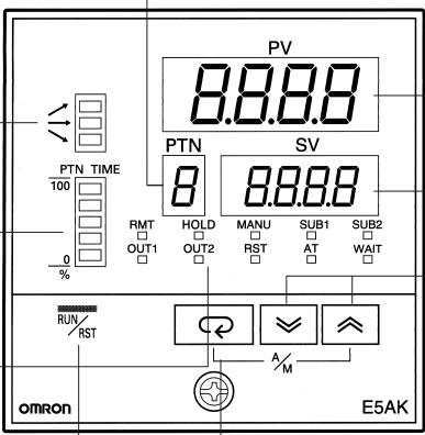
E5AK
Pattern Number
Indicates the pattern number.
Program Status Indicators
The top indicator indicates the rising step, the middle indicator indicates the constant step, and the bottom indicator indicates the falling step.
Bar Graph
Indicates the rate of pattern elapsing time at the rate of 20% (5 levels) per one segment.
Operation Indicators
OUT1
Lights when the pulse output function assigned to control output 1 turns ON.
OUT2
Lights when the pulse output function assigned to control output 2 turns ON.
- SUB1
Lights when the output function assigned to auxiliary output 1 turns ON.
- SUB2
Lights when the output function assigned to auxiliary output 2 turns ON.
- MANU
Lights when the manual operation mode.
RST
Lights when the operation is reset.
RMT
Lights during remote operation.
AT
Flashes during auto-tuning.
HOLD
Lights when the program is on hold.
WAIT
Lights when the program is waiting.
E5EK
Display 1
Displays the process value or parameter code.
Display 2
Displays the present SP, manipulated variable, or parameter settings.
Up Key/Down Key
Press to increase or decrease the value on the No.2 display.
RUN/RST Key
Switches between RUN and RESET mode.

Digital Controller
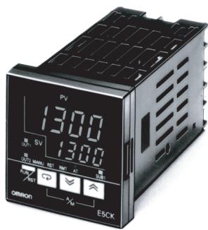
E5CK-T
Advanced, Compact Programmable Digital Controllers Ideal for Worldwide Use
- Offers up to four patterns of simple programming control (16 steps per pattern).
- IP66/NEMA4 (indoor use) front face.
Modular structure, one-stock type. - Heating/cooling control.
- Serial communications (RS-232C and RS-485).
- Temperature and analog inputs.
- High-accuracy: 100-ms sampling (for analog input).
- Conforms to international EMC and safety standards.
- 24 VAC/DC types are also available.
C E
Ordering Information
■ List of Models
| Description | Model | Specification |
| Base Unit | E5CK-TAA1 AC100-240 | Standard model |
| E5CK-TAA1-500 AC100-240 | Standard model with terminal cover | |
| E5CK-TAA1 AC/DC24 | Standard model | |
| E5CK-TAA1-500 AC/DC24 | Standard model with terminal cover |
Note: A single Output Unit and Option Unit can be mounted to each Base Unit.
| Description | Model | Specification |
| Output Unit | E53-R4R4 | Relay/Relay |
| E53-Q4R4 | Pulse (NPN)/Relay | |
| E53-Q4HR4 | Pulse (PNP)/Relay | |
| E53-C4R4 | Linear (4 to 20 mA)/Relay | |
| E53-C4DR4 | Linear (0 to 20 mA)/Relay | |
| E53-V44R4 | Linear (0 to 10 V)/Relay | |
| E53-Q4Q4 | Pulse (NPN)/Pulse (NPN) | |
| E53-Q4HQ4H | Pulse (PNP)/Pulse (PNP) |
| Description | Model | Specification |
| Option Unit | E53-CK01 | RS-232C |
| E53-CK03 | RS-485 | |
| E53-CKB | Event input: 1 point | |
| E53-CKF | Transfer output (4 to 20 mA) |
Inspection Report
The Digital Controller can be provided together with an inspection report.
Refer to the following legend with the suffix "K" when ordering a model provided together with an inspection report.
E5CK-TAA1-K
■ Accessories (Order Separately)
| Name | Model |
| Terminal Cover | E53-COV07 |
—WARNING
Do not touch any of the terminals while the power is being supplied.
Doing so may result in electric shock.
General Precautions
Be sure to observe these precautions to ensure safe use.
- Do not use the product in places where explosive or flammable gases may be present.
- Never disassemble, repair or modify the product.
- Tighten the terminal screws properly.
- Use the specified size of solderless terminals for wiring.
- Use the product within the rated supply voltage.
- Use the product within the rated load.
- The life expectancy of the output relay varies considerably according to its switching capacity and operating conditions. Be sure to use the output relay within its rated load and electrical life expectancy. If the output relay is used beyond its life expectancy, its contacts may become fused or burned.
Correct Use
If you remove the Controller from its case, never touch nor apply shock to the electronic parts inside.
Do not cover the E5□K-T. (Ensure sufficient space around the Controller to allow heat radiation.)
Do not use the Controller in the following places:
- Places subject to icing, condensation, dust, corrosive gas (especially sulfide gas or ammonia gas).
- Places subject vibration and large shocks.
- Places subject to splashing liquid or oil atmosphere.
- Places subject to intense temperature changes.
- Places subject to heat radiation from a furnace.
Be sure to wire properly with correct polarity of terminals.
When wiring input or output lines to the Controller, keep the following points in mind to reduce the influence from inductive noise:
- Allow adequate space between the high voltage/current power lines and the input/output lines.
- Avoid parallel or common wiring with high voltage sources and power lines carrying large currents.
- Using separating pipes, ducts, and shielded line is also useful in protecting the Controller, and its lines from inductive noise.
Cleaning: Do not use paint thinner or organic solvents. Use standard grade alcohol to clean the product.
Use a voltage (100 to 240 VAC at 50 / 60Hz , or 24 VDC). At power ON, the prescribed voltage level must be attained within two seconds.
Allow as much space as possible between the Controller and devices that generate a powerful high frequency (high-frequency welders, high-frequency sewing machines, etc.) or surge. These devices may cause malfunctions.
If there is a large power-generating peripheral device and any of its lines near the Controller, attach a surge suppressor or noise filter to the device to stop the noise affecting the Controller system. In particular, motors, transformers, solenoids and magnetic coils have an inductance component, and therefore can generate very strong noise.
When mounting a noise filter on the power supply to the Controller, be sure to first check the filter's voltage and current capacity, and then mount the filter as close as possible to the Controller.
Use within the following temperature and humidity ranges:
- Temperature: -10^ to 55^ (with no icing or condensation) Humidity: 35% to 85% (with no icing or condensation)
If the Controller is installed inside a control board, the ambient temperature must be kept to under 55^ , including the temperature around the Controller.
If the Controller is subjected to heat radiation, use a fan to cool the surface of the Controller to under 55^ .
Store within the following temperature and humidity ranges:
- Temperature: -25^ to 65^ (with no icing or condensation)
Humidity: 35% to 85% (with no icing or condensation)
Never place heavy objects on, or apply pressure to the Controller that may cause it to deform and deteriorate during use or storage.
Avoid using the Controller in places near a radio, television set, or wireless installing. These devices can cause radio disturbances which adversely affect the performance of the Controller.
Mounting
The dimensions of the Digital Controller conform to DIN 43700.
Recommended panel thickness is 1 to 8mm (1 to 5mm for E5CK).
Mount the Unit horizontally.
Connection
To reduce inductive noise influence, the lead wires connecting the input type to the Digital Controller must be separated from the power lines and load lines.
Use the specified compensating conductors for thermocouples. Use lead wires having a small resistance for platinum resistance thermometers.
Connection Example
Wire the terminals of the Unit using solderless terminals.
The tightening torque applied to the terminal screws of the Unit must be approximately 0.78 N · m or 8 kgf · cm .
Use the following type of solderless terminals for M3.5 screws.
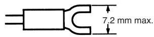
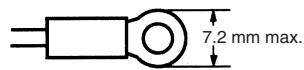
ALL DIMENSIONS SHOWN ARE IN MILLIMETERS.
To convert millimeters into inches, multiply by 0.03937. To convert grams into ounces, multiply by 0.03527.
Cat. No. H087-E1-03
In the interest of product improvement, specifications are subject to change without notice.
- Digital Controller
- E5□K-T
- Contents
- ■ Programming is as easy as following the steps below.
- E5AK-T/E5EK-T
- Advanced Programmable Digital Controllers Ideal for Worldwide Use
- Model Number Structure
- ■ Model Number Legend
- Ordering Information
- ■ List of Models
- E5AK
- Pattern Number
- Program Status Indicators
- Bar Graph
- Operation Indicators
- E5EK
- Display 1
- Display 2
- Up Key/Down Key
- RUN/RST Key
- E5CK-T
- Advanced, Compact Programmable Digital Controllers Ideal for Worldwide Use
- Inspection Report
- ■ Accessories (Order Separately)
- —WARNING
- General Precautions
- Correct Use
- Mounting
- Connection
- Connection Example
Marque : OMRON
Modèle : E5 K-T
Catégorie : Contrôleur de température