
E3X-DA-N - Capteur photoélectrique OMRON - Notice d'utilisation et mode d'emploi gratuit
Retrouvez gratuitement la notice de l'appareil E3X-DA-N OMRON au format PDF.


| Type de produit | Capteur photoélectrique amplificateur à fibre optique numérique |
| Marque | OMRON |
| Modèle | E3X-DA-N (plusieurs variantes) |
| Alimentation | 12 à 24 VDC ±10%, ondulation résiduelle ≤10% crête à crête |
| Consommation électrique | Normal : 960 mW max (40 mA à 24 V) ; Eco : 720 mW max (30 mA) ; Affichage éteint : 600 mW max (25 mA) |
| Type de sortie | NPN ou PNP (selon modèle), collecteur ouvert, 50 mA max, tension résiduelle ≤1 V |
| Mode de sortie | Light-ON / Dark-ON sélectionnable |
| Temps de réponse | Super haute vitesse : 0,25 ms ; Haute vitesse : 0,5 ms ; Standard : 1 ms ; Super longue distance : 4 ms (selon le réglage de sensibilité) |
| Réglage de sensibilité | Enseignement (teaching) manuel ou automatique, ajustement fin en mode ADJ |
| Fonctions | APC (contrôle automatique de puissance), fonction de minuterie (OFF delay, ON delay, one shot), reset zéro, reset initial, affichage numérique, sélection de mode de réponse |
| Affichage | 7 segments rouge (niveau d'incidence, seuil), barre double (niveau/ seuil), indicateur de fonctionnement orange |
| Température ambiante | Fonctionnement : -25 à +55°C (1-3 amplis), -25 à +50°C (4-11), -25 à +45°C (12-16) ; Stockage : -30 à +70°C |
| Humidité ambiante | 35% à 85% HR (sans condensation) |
| Indice de protection | IP50 (avec cache protecteur), IP66 pour modèles résistants à l'eau |
| Matériau du boîtier | PBT (polybutylène téréphtalate) |
| Poids (modèles précâblés) | Environ 100 g (110 g pour modèles avec sortie moniteur) |
| Poids (modèles à connecteur) | Environ 55 g (65 g pour sortie moniteur) |
| Connexion | Précâblé (2 m) ou type connecteur (maître/esclave) |
| Accessoires inclus | Manuel d'instructions, autocollants pour connecteurs |
| Accessoires optionnels | Console mobile E3X-MC11, connecteurs maître/esclave, supports de montage |
| Entretien et nettoyage | Nettoyer avec un chiffon sec. Ne pas utiliser de solvants. |
| Sécurité | Respecter la tension d'alimentation et les conditions ambiantes. Ne pas dépasser les charges nominales. |
| Pièces détachées et réparabilité | Contacter le SAV OMRON. Connecteurs et console mobile disponibles séparément. |
| Normes | UL listé (UL3121-1, UL991), SEMI S2-0200 |
FOIRE AUX QUESTIONS - E3X-DA-N OMRON
Questions des utilisateurs sur E3X-DA-N OMRON
0 question sur cet appareil. Repondez a celles que vous connaissez ou posez la votre.
Poser une nouvelle question sur cet appareil
Téléchargez la notice de votre Capteur photoélectrique au format PDF gratuitement ! Retrouvez votre notice E3X-DA-N - OMRON et reprennez votre appareil électronique en main. Sur cette page sont publiés tous les documents nécessaires à l'utilisation de votre appareil E3X-DA-N de la marque OMRON.
MODE D'EMPLOI E3X-DA-N OMRON
Digital Fiber Amplifier
E3X-DA-N
Truly ultimate fiber amplifier in pursuit of "user friendliness" and "high performance"
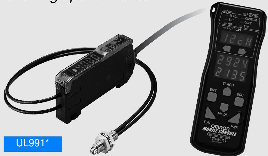
- UL-listed including UL991 tests/evaluations Applicable standard: UL3121-1 Standards for additional tests/evaluations for applications: UL991, SEMI S2-0200
Features
Reducing power line wiring meaning space is saved. New design for easier
maintenance.
Industry First | Patent pending
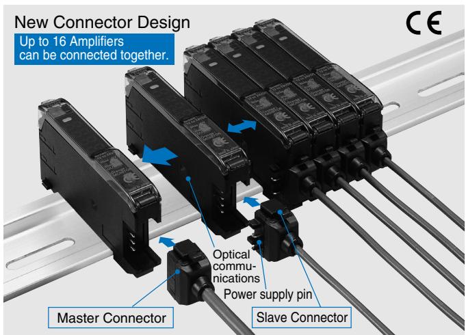
The connector type that uses the wire-saving connector supplies power to the single-conductor slave connectors via the three-conductor master connector. Hence, the following three has been made possible.
- Wiring is much simpler.
- Relay connectors are not required meaning that space is used more efficiently and costs are reduced.
- Simple inventory control because of no differentiation between master and slave in the amplifier section.
Super digital display by use of the Auto Power Control (APC) circuit Industry
Industry First
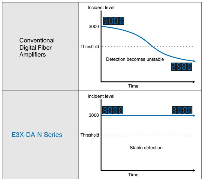
The incident level of LEDs used in sensors is prone to deteriorate with time and as a result, detection becomes unstable.
Using the APC (auto power control) circuit for the first time as the fiber sensor, the E3X-DA-N series has no digital value variations, realizing severe detection.
This makes the E3X-DA-N ideal for applications where a high degree of sensitivity is required, such as detecting crystal glass.
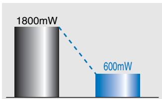
Power consumption reduced by 70% .
Previous models
E3X-DA-N
(Digital display not lit)
Power consumption has been reduced up to about 70% from 1800 mW to 600 mW. (If the digital display is off)

This ECO label is indicated on products that meet the environmental
standards established by OMRON.
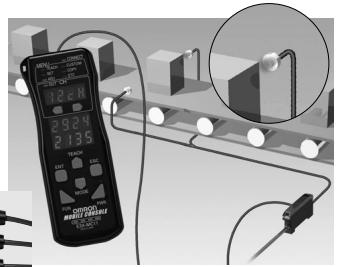
Beeper-sized, new-generation Mobile Console unleashing the power of the ultimate fiber amplifier
Remote setting/adjustment function
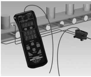
Setting/teaching/fine adjustment can be made at the fiber front-end.
The Mobile Console has enabled setting and teaching at the fiber front-end, which could only be made at the amplifier. You can perform major adjustments while looking at the work position, etc.
Incident level and threshold can be displayed simultaneously.
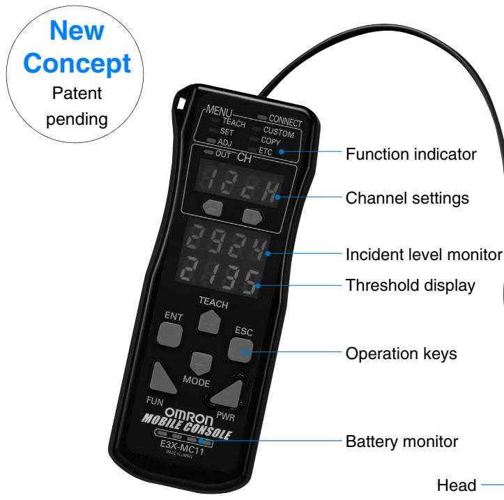
The digital display can be changed to full-OFF or Dark-ON during RUN. Eco mode
Power consumption can be reduced by setting the display to Full-OFF/Dark-ON in applications where the digital display is rarely looked at during RUN.
(Can be set at the Mobile Console only)
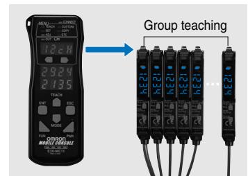
Simultaneous turning possible using group teaching.
While teaching had to be performed for each Amplifier separately, it can now be performed for several Amplifiers at once using the Mobile Console.
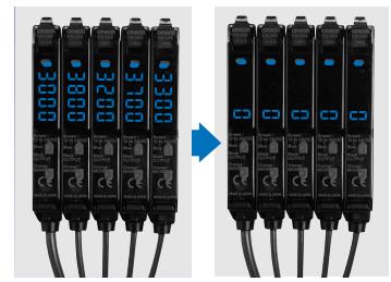
Differences in incident light avoided by group zero-reset.
The incident levels of several amplifiers can be batch-reset to zero by the group zero-reset. This feature is useful for reducing differences between the amplifiers.
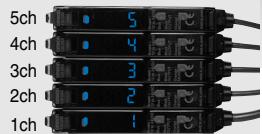
Sensor head flashing during Amplifier operation Alternatively, the amplifier channel can be displayed.
If the amplifier being operated is away from the sensor head, the sensor head can be flashed or the amplifier channel can be displayed.
Optical communications
Amplifier units
Prewired
| Item | Shape | Control output | Model | |
| NPN output | PNP output | |||
| Standard models | ON/OFF output | E3X-DA11-N | E3X-DA41-N | |
| Monitor-output models | ·ON/OFF output ·Monitor output | E3X-DA21-N | E3X-DA51-N | |
| Mark-detecting models (Blue LED) | ON/OFF output | E3X-DAB11-N | E3X-DAB41-N | |
| Mark-detecting models (Green LED) | E3X-DAG11-N | E3X-DAG41-N | ||
| Infrared models | E3X-DAH11-N | E3X-DAH41-N | ||
| Differential output type | E3X-DA11D | --- | ||
| Water-resistant models | E3X-DA11V | E3X-DA41V | ||
| Twin-output models | E3X-DA11TW | E3X-DA41TW | ||
Connector type
| Item | Shape | Applicable Connector (order separately) | Control output | Model | ||
| NPN output | PNP output | |||||
| Standard models | Master | E3X-CN11 | ON/OFF output | E3X-DA6 | E3X-DA8 | |
| Slave | E3X-CN12 | |||||
| Monitor-output models | Master | E3X-CN21 | ·ON/OFF output ·Monitor-output | E3X-DA7 | E3X-DA9 | |
| Slave | E3X-CN22 | |||||
| Mark-detecting models (Blue LED) | Master | E3X-CN11 | ON/OFF output | E3X-DAB6 | E3X-DAB8 | |
| Slave | E3X-CN12 | |||||
| Mark-detecting models (Green LED) | Master | E3X-CN11 | E3X-DAG6 | E3X-DAG8 | ||
| Slave | E3X-CN12 | |||||
| Infrared models | Master | E3X-CN11 | E3X-DAH6 | E3X-DAH8 | ||
| Slave | E3X-CN12 | |||||
| Differential output type | Master | E3X-CN11 | E3X-DA6D | --- | ||
| Slave | E3X-CN12 | |||||
| Water-resistant models (M8 Connector) | XS3F-M421-40□-AXS3F-M422-40□-A | E3X-DA14V | E3X-DA44V | |||
| Twin-output models | Master | E3X-CN21 | E3X-DA6TW | E3X-DA8TW | ||
| Slave | E3X-CN22 | |||||
Amplifier units Connectors (Order Separately) Note: Stickers for Connectors are included as accessories.
| Item | Shape | Cable length | No. of conductors | Model |
| Master connector | 2 m | 3 | E3X-CN11 | |
| 4 | E3X-CN21 | |||
| Slave connector | 1 | E3X-CN12 | ||
| 2 | E3X-CN22 |
Sensor I/O Connectors (Order separately)
| Size | Cable type | Shape | Cable length | Model | |
| M8 | Standard cable | Straight connector | 2 m | 4 conductors | XS3F-M421-402-A |
| 5 m | XS3F-M421-405-A | ||||
| L-shaped connector | 2 m | XS3F-M422-402-A | |||
| 5 m | XS3F-M422-405-A | ||||
Mobile Console (Order Separately)
| Shape | Model | Remarks |
| (Set form) E3X-MC11 | Mobile Console with head, cable, and AC adapter provided as accessories. Power supply provided by chargeable battery | |
| E3X-MC11-C1 | Mobile Console | |
| E3X-MC11-H1 | Head | |
| E39-Z12-1 | Cable (1.5 m) |
In general, amplifier units and connectors are sold separately.
Refer to the following tables for order placement.
| amplifier units | ||
| Type | NPN | PNP |
| Standard models | E3X-DA6 | E3X-DA8 |
| Mark-detecting models | E3X-DAB6 | E3X-DAB8 |
| E3X-DAG6 | E3X-DAG8 | |
| Infrared models | E3X-DAH6 | E3X-DAH8 |
| Differential output | E3X-DA6D | --- |
| Monitor-output models | E3X-DA7 | E3X-DA9 |
| Twin-output models | E3X-DA6TW | E3X-DA8TW |
+
| Applicable Connector (order separately) | |
| Master connector | Slave connector |
| E3X-CN11 | E3X-CN12 |
| E3X-CN21 | E3X-CN22 |
When using 5 sets
| amplifier units (5 Units) | + | 1 Master Connector + 4 Slave Connectors |
Amplifier units
Prewired
| Item | Type | Standard models | Monitor-out-put models | Mark-detecting models | Infrared models | Water-resis-tant models | Twin-output models | ||
| NPN output | E3X-DA11-N | E3X-DA21-N | E3X-DAB11-N | E3X-DAG11-N | E3X-DAH11-N | E3X-DA11V | E3X-DA11TW | ||
| PNP output | E3X-DA41-N | E3X-DA51-N | E3X-DAB41-N | E3X-DAG41-N | E3X-DAH41-N | E3X-DA41V | E3X-DA41TW | ||
| Light source(wave length) | Red LED (660 nm) | Blue LED(470 nm) | Green LED(525 nm) | Infrared LED(870 nm) | Red LED (660 nm) | ||||
| Power supply voltage | 12 to 24 VDC ±10%, ripple (p-p): 10% max. | ||||||||
| Power consumption | Normal: Power consumption 960 mW max. (power consumption 40 mA max. at supply voltage 24 V) Eco mode: Power consumption 720 mW max. (power consumption 30 mA max. at supply voltage 24 V) Digital display OFF: Power consumption 600 mW max. (power consumption 25 mA max. at supply voltage 24 V) | ||||||||
| Control output | ON/OFF output | Load current 50 mA (residual voltage NPN/PNP: 1 V max. each) Open collector output type (depends on the NPN/PNP output format) Light-ON/Dark-ON, switch selectable | |||||||
| Monitor output | --- | 1 to 5 VDC,load 10 kmin. | --- | ||||||
| Protective circuits | Reverse polarity protection, output short-circuit protection, mutual interference prevention (possible for up to 10 amplifiers) | ||||||||
| Re-spons e time | Super-high-speed mode: | 0.25 ms for operation and reset respectively | 0.5 ms for operation and reset respectively | ||||||
| Standard mode: | Operation/reset: 1 ms each | 2 ms for operation and reset respectively | |||||||
| Super-long-dis-tance mode: | 4 ms for operation and reset respectively | 7 ms for operation and reset respectively | |||||||
| Sensitivity setting | Teaching or manual method | ||||||||
| Func-tions | Timer functions | OFF delay 0 to 200 ms (1 to 20: 1 ms increments, 20 to 200 ms: 5 ms increments), when the Mobile Control is used, select either OFF delay, ON delay or one shot. | |||||||
| Automatic pow-er control (APC) | Fiber-optic current digital con-trol | --- | Fiber-optic current digital control | ||||||
| Zero reset | Yes (negative indication possible) | ||||||||
| Initial reset | Yes (setting conditions initialized) | ||||||||
| Monitor focus | --- | Upper and lower limit values of output range can be set per digital value of 100 | --- | ||||||
| Indicator lamp | Operation indicator (orange), 7-segment digital incident level display (red), 7-segment digital incident level percent display (red), incident level & threshold value double-bar display (green, red), 7-segment digital threshold value display (red) | ||||||||
| Display timing | Normal/peak hold/bottom hold selectable | ||||||||
| Display direction | Normal/reverse selectable | ||||||||
| Optical axis adjustment function | Yes (hyper flashing emission function) | ||||||||
| Ambient lighting | Incandescent lamp: 10,000 lux max. Sunlight 20,000 lux max. | ||||||||
| Ambient temperature | Operating: Groups of 1 to 3 amplifiers: -25 to +55°C, Groups of 4 to 11 amplifiers: -25 to +50°C, Groups of 12 to 16 amplifiers: -25 to +45°C Storage: -30 to +70°C (with no icing and condensation) | ||||||||
| Ambient humidity | Operating/Storage: 35% to 85% RH (with no condensation) | ||||||||
| Item\Model | Type | Standard models | Monitor-out-put models | Mark-detecting models | Infrared models | Water-resis-tant models | Twin-output models | |
| NPN output | E3X-DA11-N | E3X-DA21-N | E3X-DAB11-N | E3X-DAG11-N | E3X-DAH11-N | E3X-DA11V | E3X-DA11TW | |
| PNP output | E3X-DA41-N | E3X-DA51-N | E3X-DAB41-N | E3X-DAG41-N | E3X-DAH41-N | E3X-DA41V | E3X-DA41TW | |
| Insulation resistance | 20 M min. at 500 VDC | |||||||
| Dielectric strength | 1,000 VAC at 50/60 Hz for 1 minute | |||||||
| Vibration resistance | 10 to 55 Hz, 1.5 mm double amplitude for 2 hours each in X, Y, and Z directions | |||||||
| Shock resistance | Destruction: 500 m/s2 for 3 times each in X, Y, and Z directions | |||||||
| Degree of protection | IEC 60529 IP50 (with Protective Cover attached) | IEC 60529 IP66 (with protective cover attached) | IEC 60529 IP50 (with protective cover attached) | |||||
| Connection method | Prewired models (standard length: 2 m) | |||||||
| Weight (Packed state) | Approx. 100 g | Approx. 110 g | Approx. 100 g | |||||
| Material | Case | PBT (polybutylene terephthalate) | ||||||
| Cover | Polycarbonate | Polyethersul-fone | ||||||
| Accessories | Instruction manual | |||||||
Connector type
Specifications that differ from those of the prewired type
| Model Item | Type | Standard models | Monitor-out-put models | Mark-detecting models | Infrared models | Water-resis-tant models (See note.) | Twin-out-put models | |
| NPN output | E3X-DA6 | E3X-DA7 | E3X-DAB6 | E3X-DAG6 | E3X-DAH6 | E3X-DA14V | E3X-DA6TW | |
| PNP output | E3X-DA8 | E3X-DA9 | E3X-DAB8 | E3X-DAG8 | E3X-DAH8 | E3X-DA44V | E3X-DA8TW | |
| Connection method | Connector type | M8 connector | Connector | |||||
| Weight (Packed state) | Approx. 55 g | 65 g | Approx. 55 g | |||||
- For waterproof type only, voltage resistance is 500 VAC 50/60 Hz 1 min
Amplifier unit Connectors
| Item | Model | E3X-CN11/21/22 | E3X-CN12 |
| Rated current | 2.5 A | ||
| Rated voltage | 50 V | ||
| Contact resistance | 20 m max. (20 mVDC max., 100 mA max.) [By connection with amplifier unit and connection with adjacent connector (except conductor resistance of cable)] | ||
| No. of insertions | 50 times (By connection with amplifier unit and connection with ad-jacent connector) | ||
| Material | Housing | PBT (polybutylene terephthalate) | |
| Contacts | Phosphor bronze/gold-plated nickel | ||
| Weight (Packed state) | Approx. 55 g | Approx. 25 g | |
Mobile Console
| Item Model | E3X-MC11 |
| Supply voltage | Charged with AC adapter |
| Connection method | Connected via adapter |
| Weight (packed state) | Approx. 580 g (Console only: 120 g) |
| For details of the Mobile Console, refer to the instruction manual attached to the product. | |
- Differential output digital fiber amplifier (E3X-DA11D/E3X-DA6D)
Applicable fiber unit characteristic
(Through-beam model)
| Sensitivity switching 11 steps can be set Fiber type | Sensing distance (mm) (Values in parentheses: When using the E39-F1 lens unit) | Standard object (mm)*1 Minimum sensing object *2 (Opaque object) de-fault | |||||
| HIGH | LOW | ||||||
| 1 | 2 | 3-11 | 1 | 2 | 3-11 | ||
| 270 or 570 s | 0.5 or 1 ms | 1 to 200 ms or 2 to 400 ms | 270 or 570 s | 0.5 or 1 ms | 1 to 200 ms or 2 to 400 ms | ||
| E32-ET11R | 240 (1680) | 280 (1960) | 370 (2590) | 140(980) | 180(1260) | 240 (1680) | 1 mm dia. (0.01 mm dia.) |
| E32-ET21R | 50 | 60 | 80 | 30 | 40 | 50 | |
| E32-T16WR | 580 | 690 | 910 | 350 | 450 | 580 | (0.3 mm dia.)*3 |
| E32-T16PR | 380 | 450 | 600 | 230 | 290 | 380 | (0.2 mm dia.) |
1. The sensing object is operating.
2. Value applied when the response time is set to 3-11. The value can be detected if the temperature varies within the operating ambient temperature. (Value when the sensing object is operating)
*3. The digital value is 1000 and the value can be detected in each detection area.
Refer to the E3X-DA-N for the note of the fiber unit.
(Reflective model)
| Sensitivity switching 11 steps can be set Fiber type | Sensing distance (mm)*1 | Standard object (mm)*2 Minimum sensing object *3 (Opaque object) de-fault | |||||
| HIGH | LOW | ||||||
| 1 | 2 | 3-11 | 1 | 2 | 3-11 | ||
| 270 or 570 s | 0.5 or 1 ms | 1 to 200 ms or 2 to 400 ms | 270 or 570 s | 0.5 or 1 ms | 1 to 200 ms or 2 to 400 ms | ||
| E32-ED11R | 80 | 90 | 120 | 45 | 60 | 80 | 150 x 150 (0.01 mm dia.) |
| E32-ED21R | 13 | 15 | 20 | 7 | 10 | 13 | 25 x 25 (0.01 mm dia.) |
1. Sensing distance indicates values for white paper.
2. The sensing object is operating.
*3. Value applied when the response time is set to 3-11. The value can be detected if the temperature varies within the operating ambient temperature. (Value when the sensing object is operating)
Note: Refer to E3X-DA-N for the note of the fiber unit.
Differences from E3X-DA-N amplifier unit
| Item Item NPN output | Differential output type (edge detection type) | ||
| Prewiring type | amplifier units with Connectors | ||
| E3X-DA11D | E3X-DA6D | ||
| Power consumption | Power consumption 960 mW max. (at power supply voltage 24 V, power consumption 40 mA max.) | ||
| Control output | ON/OFF output | Load current 50 mA (residual voltage NPN/PNP: 1 V max. each) Open collector output type L.ON (ON at edge detection)/D.ON (OFF at edge detection) switch selectable | |
| Detection mode | One-side edge detection mode/both-side edge detection mode | ||
| Response time | One-side edge detection mode: 270/500 s/1/2/4/10/20/30/50/100/200 ms selectable Both-side edge detection mode: 570 s/1/2/4/10/20/30/50/100/200/400 ms selectable | ||
| Functions | Timer function | OFF delay timer for L.ON ON delay timer for D.ON 0 to 5 s (1 to 20 ms: 1 ms increments, 20 to 20 ms: 5 ms increments, 200 ms to 1 s: 100 ms, 1 to 5 s: 1 s increments) | |
| APC | Yes | ||
| Zero reset | Yes (negative indication) | ||
| Initial reset | Yes (setting conditions initialized) | ||
| Sensitivity switching | Yes (HIGH/LOW) | ||
| Teaching level | One-point teaching level 1 to 50% variable (1% increments) | ||
| Indicator lamp | Operation indicator (orange), 7-segment incident level display (red), 7-segment digital edge detection level display (red) | ||
For the outline drawings and other details, refer to the instruction manuals attached to the products.
NPN output
| Model | Output transistor Status | Timing chart | Mode selection switch | Output circuit |
| E3X-DA11-N | Light ON | Incident light No incident light Operation ON T Output Indicator (orange) OFF Load Operate (relay) Release (Between brown and black) | L ON (LIGHT ON) | Operation Indicator (orange) 1 Main circuit 2 Control output 3 Blue 12 to 24 VDC |
| E3X-DAB11-N | ||||
| E3X-DAG11-N | ||||
| E3X-DAH11-N | ||||
| E3X-DA11V | ||||
| E3X-DA6 | ||||
| E3X-DAB6 | ||||
| E3X-DAG6 | ||||
| E3X-DAH6 | ||||
| E3X-DA14V | ||||
| Dark ON | Incident light No incident light Operation ON T Output Indicator (orange) OFF Load Operate (relay) Release (Between brown and black) | D ON (DARK ON) | Connector Pin Arrangement ②④ ①③ Note: Pin 2 is not used. | |
| E3X-DA21-N | Light ON | Incident light No incident light Operation ON T Output Indicator (orange) OFF Load Operate (relay) Release (Between brown and black) | L ON (LIGHT ON) | Operation Indicator (orange) 12 to 24 VDC Monitor output (see note) |
| E3X-DA7 | ||||
| Dark ON | Incident light No incident light Operation ON T Output Indicator (orange) OFF Load Operate (relay) Release (Between brown and black) | D ON (DARK ON) | Note: Load resistance: 10Ωmin. | |
| E3X-DA11TW | Light ON | CH1/ Incident light CH2 No incident light Operation ON T Output Indicator (orange) OFF Load Operate (relay) Release (Between brown and black) | L ON (LIGHT ON) | Operation Indicator (orange) 12 to 24 VDC Control output 2 Blue 12 to 24 VDC |
| E3X-DA6TW | ||||
| Dark ON | CH1/ Incident light CH2 No incident light Operation ON T Output Indicator (orange) OFF Load Operate (relay) Release (Between brown and black) | D ON (DARK ON) |
Note: With E3X-DA□TW models, only channel 1 is output when set for area sensing operation.
L ON The range between the CH1 and CH2 thresholds turns ON
D ON The range between the CH1 and CH2 thresholds turns OFF (CH2 is always OFF)
PNP output
| Model | Output transistor Status | Timing chart | Mode selection switch | Output circuit |
| E3X-DA41-N | Light ON | Incident light No incident light Operation ON T Inductor OFF Output transistor OFF Load Operate (relay) Release (Between blue and black) | L ON (LIGHT ON) | Operation Indicator (orange) Display Main circuit Control output 12 to 24 VDC Blue ① ② ③ Note: Pin 2 is not used. |
| E3X-DAB41-N | ||||
| E3X-DAG41-N | ||||
| E3X-DA41N | ||||
| E3X-DAG8 | Dark ON | Incident light No incident light Operation ON T Inductor OFF Output transistor OFF Load Operate (relay) Release (Between blue and black) | D ON (DARK ON) | |
| E3X-DAG8 | ||||
| E3X-DAG8 | ||||
| E3X-DA44V | ||||
| E3X-DA48 | Light ON | Incident light No incident light Operation ON T Inductor OFF Output transistor OFF Load Operate (relay) Release (Between blue and black) | L ON (LIGHT ON) | Operation Indicator (orange) Display Main circuit Monitor output 1 to 5 V Orange Load Blue 12 to 24 VDC Note: Load resistance: 10kΩmin. |
| E3X-DA48 | ||||
| E3X-DAB8 | ||||
| E3X-DAG8 | ||||
| E3X-DAH8 | ||||
| E3X-DA44V | ||||
| E3X-DA51-N | Light ON | Incident light No incident light Operation ON T Inductor OFF Output transistor OFF Load Operate (relay) Release (Between blue and black) | D ON (DARK ON) | |
| E3X-DA51-N | ||||
| E3X-DA9 | Dark ON | Incident light No incident light Operation ON T Inductor OFF Output transistor OFF Load Operate (relay) Release (Between blue and black) | L ON (LIGHT ON) | Operation Indicator (orange) Display Main circuit Control output 1→Black Control output 2 Orange Load Blue 12 to 24 VDC Note: Load resistance: 10kΩmin. |
| E3X-DA51-TW | Light ON | CH1/Incident light CH2 No incident light Operation ON T Inductor OFF Output transistor OFF Load Operate (relay) Release (Between blue and black) | D ON (DARK ON) | |
| E3X-DA41TW | Dark ON | CH1/Incident light CH2 No incident light Operation ON T Inductor OFF Output transistor OFF Load Operate (relay) Release (Between blue and black) | D ON (DARK ON) | |
| E3X-DA8TW |
Note: With E3X-DA□TW models, only channel 1 is output when set for area sensing operation.
L ON The range between the CH1 and CH2 thresholds turns ON
D ON The range between the CH1 and CH2 thresholds turns OFF (CH2 is always OFF)
Connectors (Sensor I/O Connectors)
XS3F-M421-402A
XS3F-M421-405A
X53F-M422-402A
X5SF-M422-405A
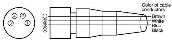
| Class | Wire, outer jacket color | Connector pin No. | Application |
| For DC | Brown | ① | Power sup-ply (+V) |
| White | ② | - | |
| Blue | ③ | Power sup-ply (0 V) | |
| Black | ④ | Output |
Note: Pin 2 is open.
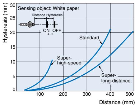
Hysteresis vs. sensing distance
Reflective model E32-D11L
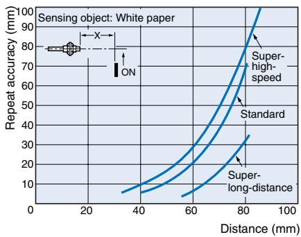
Repeated accuracy vs. sensing distance
Reflective model E32-DC200
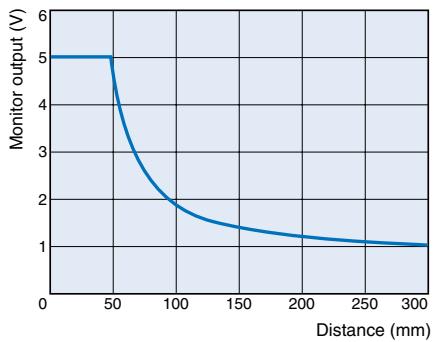
Monitor output vs. distance (In standard mode)
Through-beam E32-TC200
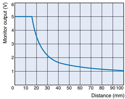
Reflective model E32-DC200
Connection
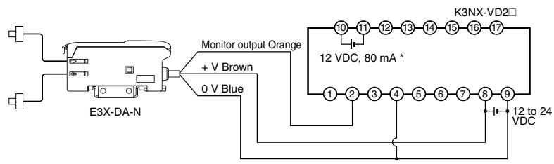
Connection with linear sensor controller K3NX-VD2
- Use this service power supply for the Sensor with reference to the power consumption of each Sensor.
Note: 1. Various I/O Units are available for the K3NX. Select an appropriate output type depending on the application.
2. For details about the K3NX, refer to the K3NX Datasheet (N084) or the K3NX Operation Manual (N90).
3. This wiring is for the K3NX, with DC power supply specifications and the Monitor (Analog) Sensor with DC power supply specifications. Check respective power supply specifications before wiring them.
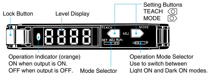
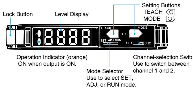
Nomenclature:
amplifier units
Standard, monitor-output, mark-detecting, infrared, and water-resistant models
Twin-output models
General
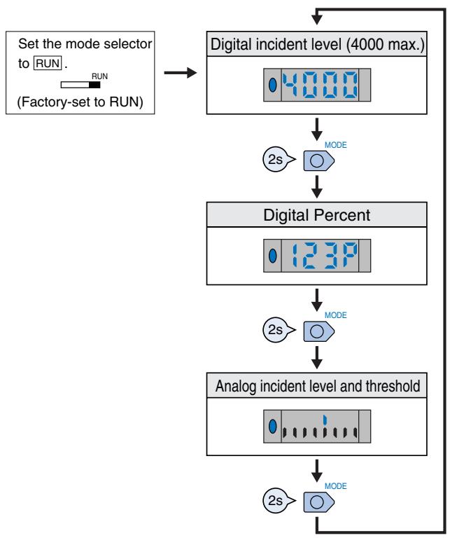
1 Changing the Display (RUN Mode)
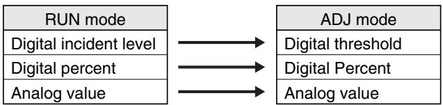
- Manual Tuning (Fine Sensitivity Adjustment) in ADJ Mode
- Perform fine sensitivity adjustment after teaching and manual tuning (without using the teaching function) in the way shown below:
The items displayed in ADJ mode vary with the display setting in RUN mode.
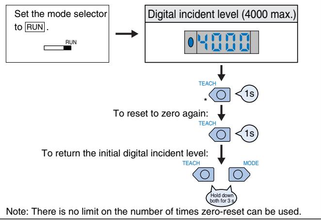
2 Zero-reset (RUN Mode)

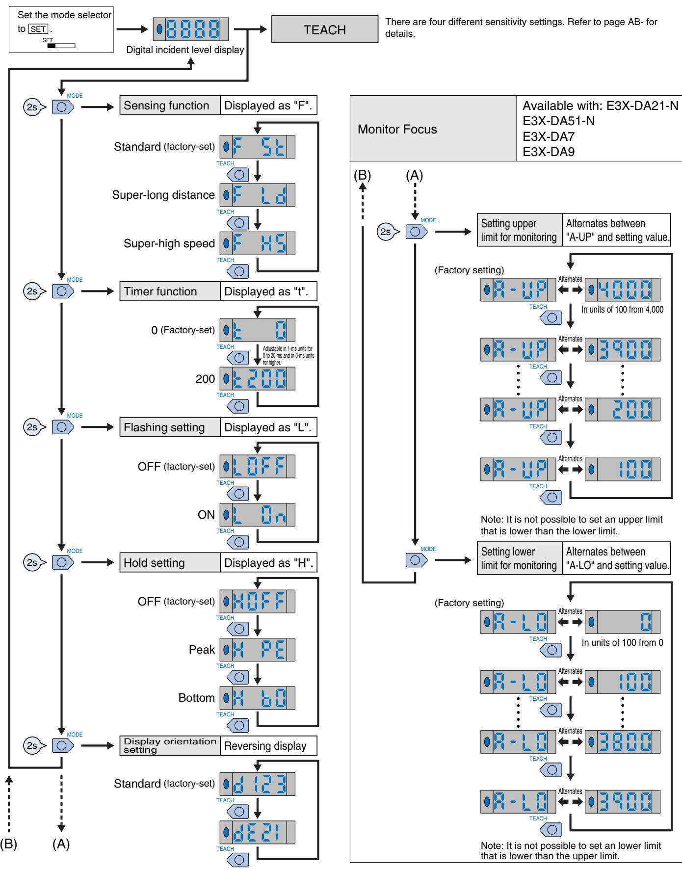
3 Initial Reset (SET Mode)
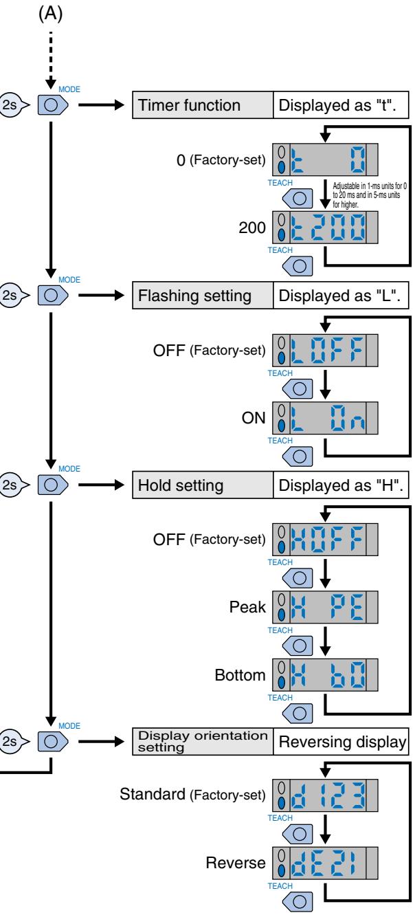
4 Setting Functions in SET Mode
Twin-output models
4 Setting Functions in SET Mode
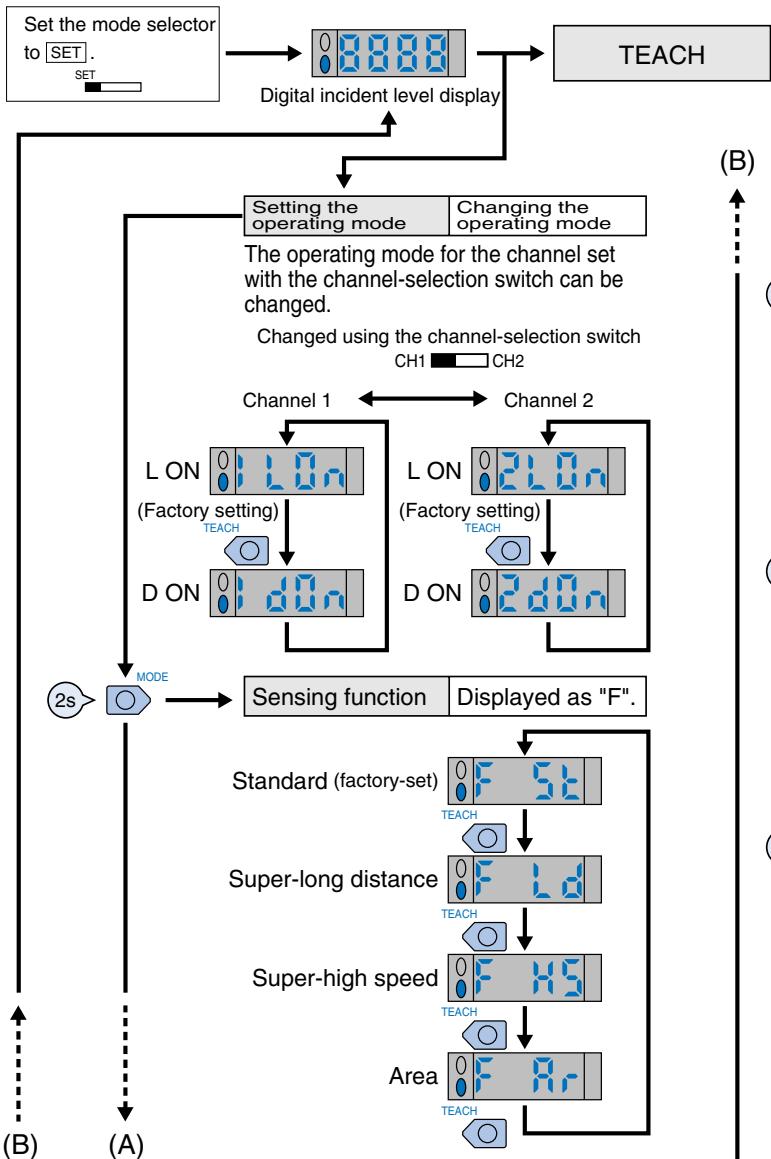
There are four different sensitivity settings. Refer to page AB- for details.
Area Sensing
Area sensing is possible using the threshold values for channels 1 and 2.
- If channel 1 is set to L/ON, output turns ON when the incident level is between the thresholds.
- If channel 1 is set to D/ON, output turns OFF when the incident level is between the thresholds.
The result is output to control output 1.
(Control output 2 is always OFF.)
General
When teaching is performed (SET mode)
- The four types of teaching given below are available.
- Once setting is made, operation is performed in the preset status thereafter. When a teaching error occurs, the level indicators flash in red. Restart setting from the beginning.
Twin-output models only
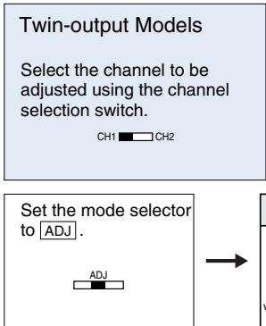
Select the channel to be adjusted using the channel selection switch.
Set the mode selector to SET

Maximum Sensitivity Setting
| Procedure | Operation |
| 1 | Set the mode selector to SET. |
| 2 | Press the TEACH button for 3 seconds min. |
| 3 | Setting is completed when the red-lit level indicators turn to green. Then they return to the digital incident level display. |
| 4 | Set to RUN mode. |
One-point without-object teaching
| Procedure | Operation | |
| 1 | Set the mode selector to SET. | SET |
| 2 | Press the SET button once (about 1 s). | TEACH 1s |
| 3 | Setting is completed when the red level indicators are turned ON. They then return to the digital incident level display. | (red) |
| 4 | Set to RUN mode. | RUN |
| 5 | The threshold is automatically set with the object. | Object ON Output |
Note: If one-point teaching is not available because the difference in level is too fine, try two-point teaching.
Operation Mode Selector
| Operating mode | Operation | |
| Light ON | L ON | L (Factory-set) |
| Dark ON | D ON | D |
There is no operation mode selector for twin-output models.
Two-point With/Without-object Teaching
| Procedure | Operation | |
| 1 | Set the mode selector to SET. | SET |
| 2 | With the work present, press the SET button once (about 1 s). | Object |
| TEACH | ||
| 3 | The level indicators are lit red. | (red) |
| 4 | If no work is pending, press the SET button once (about 1 s). | TEACH |
| 5 | Setting is completed when the green indicators are turned ON. Then they return to the digital incident level display. | green) |
| 6 | Set to RUN mode. | RUN |
Note: With and without work may be in any order.
Pin-point teaching (for positioning)
| Procedure | Operation | |
| 1 | Set the mode selector to SET. | SET |
| 2 | If no work is pending, press the SET button once (about 1 s). | TEACH 1s |
| 3 | The level indicators are lit red. | (red) |
| 4 | Place the object in the desired position, and press the TEACH button for 3 seconds min. | TEACH 3s |
| 5 | Setting is completed when the green indicators are turned ON. Then they return to the digital in-cident level display. (Red indicators start flashing if setting is not OK.) | (green) |
| 6 | Set to RUN mode. | RUN |
Correct Use
Amplifier units
Design
Power ON
The sensor is ready to sense an object within 200 ms after turning the power ON. If the load and sensor are connected to different power supplies, always turn on the sensor power first.
Mounting
Connection/removing of amplifier units
(Connection)
- Install the units one by one to the DIN rail.
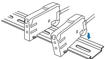
- Slide one unit toward the other, match the clips at the front ends, and then bring them together until they "click".
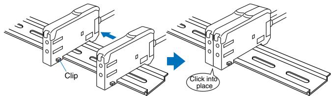
(Removing)
Slide one unit away from the other and remove them one by one. (Do not remove the connected units together from the DIN rail.)
Note:1. When the amplifier units are connected to each other, the operable ambient temperature changes depending on the number of connected amplifier units. Check "Ratings/Performance".
2. Before connecting or removing the units, always switch power off.
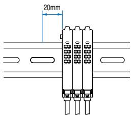
Fitting of Mobile Console head
When fitting the Mobile Console head, a 20 mm or more clearance is needed on the left side.
Use of Mobile Console
For the twin output type (E3X-DA□□TW), up to 16 channels (eight E3X-DA□□TW units) can be set from the Mobile Console E3X-MC11. (Note that the operation mode and area detection cannot be set.)
Adjustment
Mutual interference prevention function
The digital display value may vary due to the light from the other sensor. In that case, low the sensitivity (raise the threshold) to stabilize detection.
EEPROM Write Error
If a write error occurs (operation indicator starts flashing) due to power-off, static electricity or other noise in the teaching mode, perform teaching again.
Optical communication
When connecting the amplifier units, assemble them in close contact. During operation, do not slide or dismantle the amplifier units.
Hysteresis adjustment
The Mobile Console allows hysteresis adjustment, but note that the unit may not operate properly if the hysteresis setting is lower than the factory value.
Amplifier Unit Connectors
Installation
Connector installation
- Insert the Master or Slave Connector into the amplifier unit until it clicks into place.
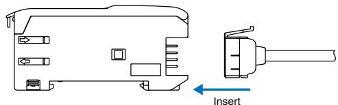
- Link amplifier units to each other after the master and slave Connectors have been inserted.
- Apply the supplied seal to the non-connecting surface of the master/slave connector.
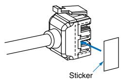
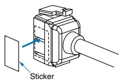
Note: Apply seal to the grooved side.
Removing Connectors
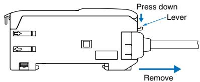
- Slide the slave amplifier unit (s) on which the connector must be removed from the rest of the group.
- After the amplifier unit (s) has been separated, press down the lever on the connector and remove it. (Do not attempt to remove connectors without separating them from other amplifier units first.)
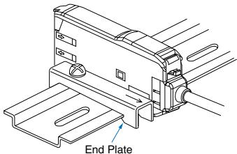
Mounting End Plate (PFP-M)
Depending on the installation, an amplifier unit may move during operation. In this case, use an end plate.
Before installing an end plate, remove the clip from the master amplifier unit using a nipper or similar tool.
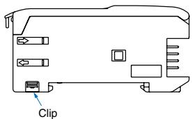
The sensor bottom is also equipped with a clip removing mechanism.
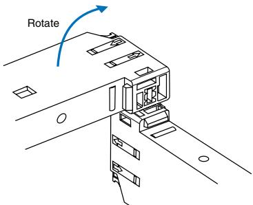
- Insert the clip to be removed into the slit underneath the clip on another amplifier unit.
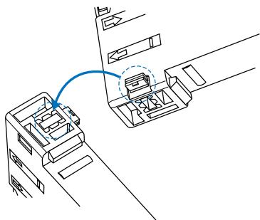
- Remove the clip by rotating the amplifier unit.
When fitting the Mobile Console, set the end plate in the guide as shown in the following figure.
Tensile stress for connectors (including cables)
E3X-CN11, E3X-CN21, E3X-CN22: 30 N max.
E3X-CN12: 12N max.
Amplifier Units
E3X-DA11-N E3X-DAG11-N E3X-DA21-N
E3X-DAH11-N E3X-DAB11-N E3X-DAB41-N
E3X-DA41-N E3X-DAG41-N E3X-DA51-N
E3X-DAH41-N E3X-DA11D
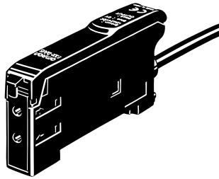
prewired
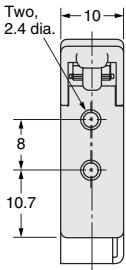
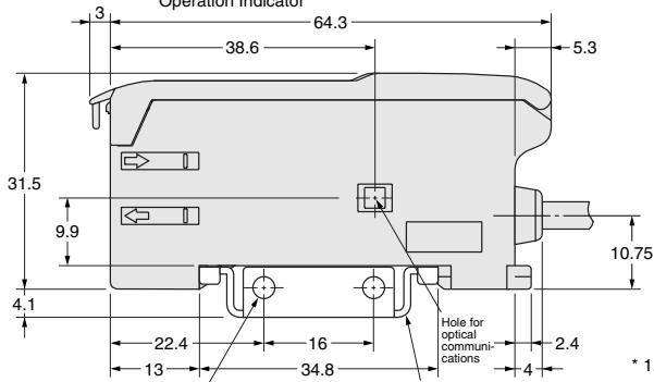
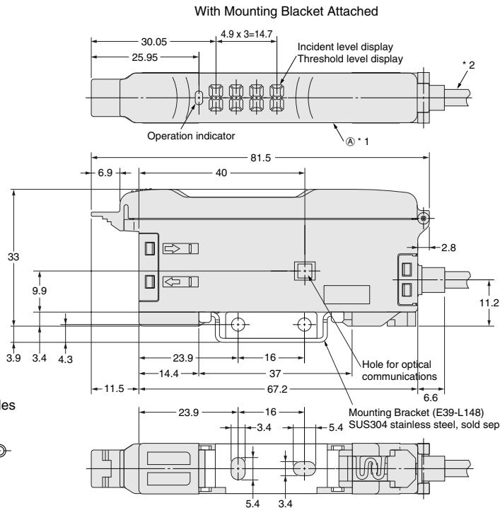
With Mounting Blanket Attached
Operation Indicator
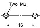
Two, 3.2 dia. holes
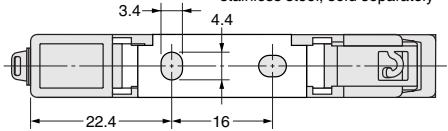
Mounting Bracket (E39-L143)SUS304 stainless steel, sold separately
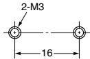
Mounting Holes
2. E3X-DA11-N/DA41-N/DAB11-N: A 4-dia., 3-conductor, vinyl-insulated round cable (conductor cross-sectional area: 0.45mm^2 ; insulation diameter: 1.1mm ) is used. E3X-DA21-N/DA51-N: A 4-dia., 4-conductor, vinyl-insulated round cable (conductor cross-sectional area: 0.2mm^2 ; insulation diameter: 1.1mm is used.
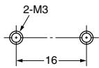
1. The Mounting Bracket can also be used on side A.
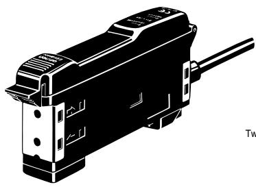
Amplifier units with Cables, Water-resistant Models
E3X-DA11V
E3X-DA41V
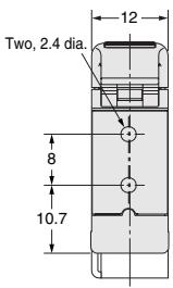
* 1. The mounting Bracket can also be used on side A.
*2. 4-dia., 3-conductor, vinyl-insulated round cable (conductor cross-sectional area: 0.2mm^2 ; insulation diameter: 1.1mm is used.
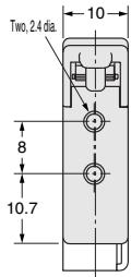
Mounting Holes
Indicator
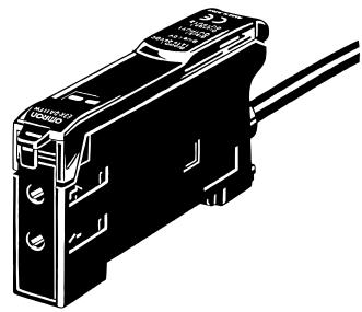
Amplifier units with Cables, Twin-output Models
E3X-DA11TW
E3X-DA41TW
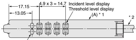
With Mounting Blanket Attached
Operation Indicator
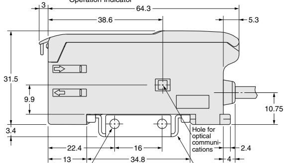
Two, 3.2 dia. holes
Mounting Bracket (E39-L143)SUS304
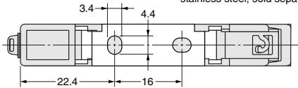
stainless steel, sold separately
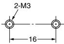
Mounting Holes
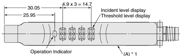
Connector type
E3X-DA6E3X-DAG6
E3X-DA7E3X-DAH6
E3X-DA8E3X-DAB8
E3X-DA9E3X-DAG8
E3X-DAB6E3X-DAH8
E3X-DA6D
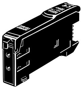
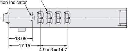
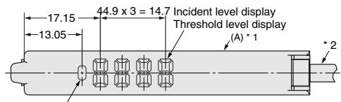
Incident level display
Threshold level display
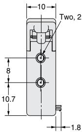
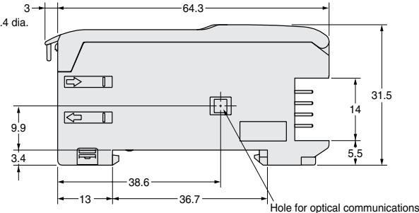
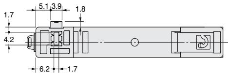
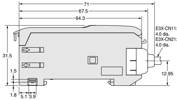
Dimensions with Master Connector Connected
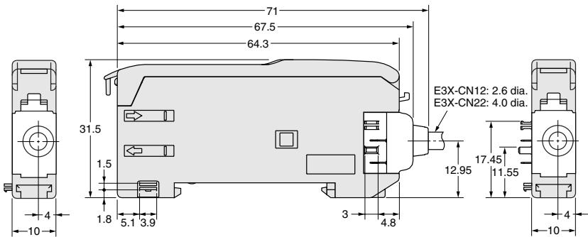
Dimensions with Slave Connector Connected
Amplifier Units M8 Connectors, Water-resistant Models
E3X-DA14V
E3X-DA44V
- The Mounting Bracket can also be on side A.
With Mounting Bracket Attached
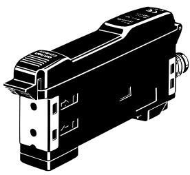
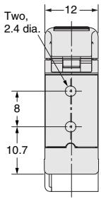
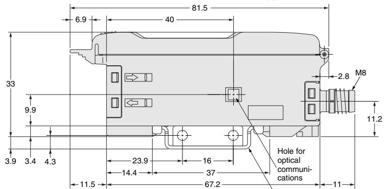
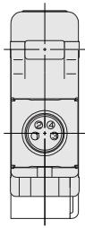
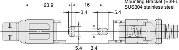
Mounting Bracket (E39-L148), Sold separately SUS304 stainless steel
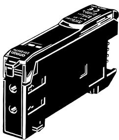
Amplifier units with Standard Connectors, Twin-output Models
E3X-DA6TW
E3X-DA8TW
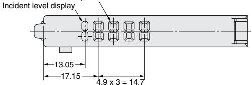
Threshold level display
Operation Indicator
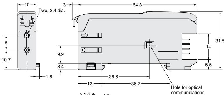
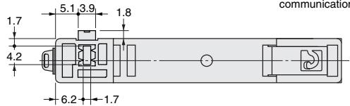
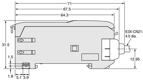
Dimensions with Master Connector Connected
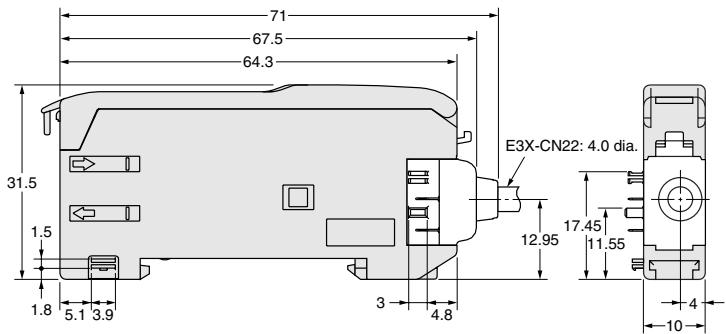
Dimensions with Slave Connector Connected
Amplifier Unit Connectors
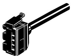
Master connector
E3X-CN11
E3X-CN21
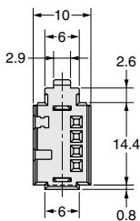

* E3X-CN11: A 4-dia., 3-conductor, vinyl-insulated round cable (conductor cross-sectional area: 0.2 mm^2 ; insulation diameter: 1.1 mm ) is used. E3X-CN21: A 4-dia., 4-conductor, vinyl-insulated round cable (conductor cross-sectional area: 0.2 mm^2 ; insulation diameter: 1.1 mm ) is used.
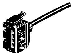
Slave connector
E3X-CN12
E3X-CN22
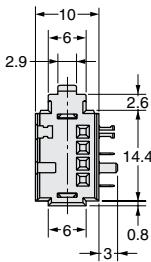

* E3X-CN12: A 2.6-dia., single-conductor, vinyl-insulated round cable (conductor cross-sectional area: 0.2 mm^2 ; insulation diameter: 1.1 mm ) is used. E3X-CN22: A 4-dia., 2-conductor, vinyl-insulated round cable (conductor cross-sectional area: 0.2 mm^2 ; insulation diameter: 1.1 mm ) is used.
Mobile Console
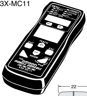
E3X-MC11
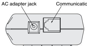
Mobile Console
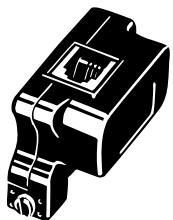
Mobile Console head
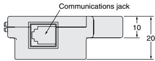
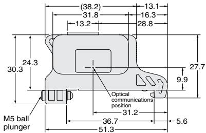
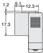
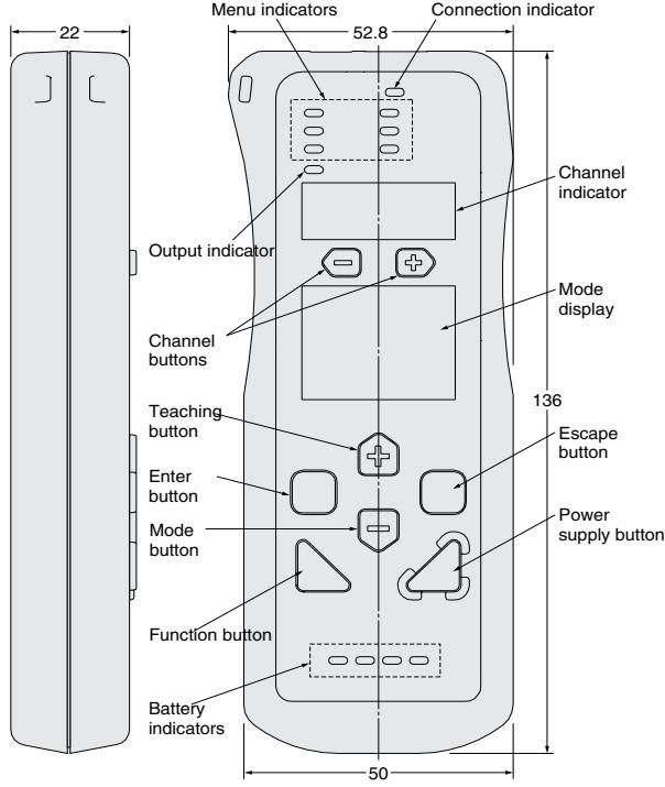
ALL DIMENSIONS SHOWN ARE IN MILLIMETERS.
To convert millimeters into inches, multiply by 0.03937. To convert grams into ounces, multiply by 0.03527.
Cat. No. E22E-EN-01
In the interest of product improvement, specifications are subject to change without notice.
- Digital Fiber Amplifier
- E3X-DA-N
- Features
- Reducing power line wiring meaning space is saved. New design for easier
- Super digital display by use of the Auto Power Control (APC) circuit Industry
- Power consumption reduced by 70\% .
- Beeper-sized, new-generation Mobile Console unleashing the power of the ultimate fiber amplifier
- Remote setting/adjustment function
- Incident level and threshold can be displayed simultaneously.
- The digital display can be changed to full-OFF or Dark-ON during RUN. Eco mode
- Simultaneous turning possible using group teaching.
- Differences in incident light avoided by group zero-reset.
- Sensor head flashing during Amplifier operation Alternatively, the amplifier channel can be displayed.
- Connector type
- Connection
- Nomenclature:
- amplifier units
- Twin-output models
- General
- Setting Functions in SET Mode
- Area Sensing
- When teaching is performed (SET mode)
- Correct Use
- Mounting
- Connection/removing of amplifier units
- Fitting of Mobile Console head
- Use of Mobile Console
- Adjustment
- EEPROM Write Error
- Optical communication
- Hysteresis adjustment
- Amplifier Unit Connectors
- Connector installation
- Removing Connectors
- Mounting End Plate (PFP-M)
- Amplifier units with Cables, Water-resistant Models
- Mobile Console
Marque : OMRON
Modèle : E3X-DA-N
Catégorie : Capteur photoélectrique