
E3F2-Z - Capteur de proximité OMRON - Notice d'utilisation et mode d'emploi gratuit
Retrouvez gratuitement la notice de l'appareil E3F2-Z OMRON au format PDF.


| Type de produit | Capteur de proximité photoelectrique |
| Marque | OMRON |
| Modèle | E3F2-Z |
| Catégorie | Capteur de proximité |
| Méthode de détection | Traversant, rétroréfléchissant, diffus (selon modèle) |
| Distance de détection nominale | 3 m (traversant), 0,1 à 2 m (rétroréfléchissant avec réflecteur E39-R1), 0,1 m (diffus) |
| Tension d'alimentation | 24 à 240 VAC, 50/60 Hz |
| Consommation | 10 mA max (traversant), 5 mA max (autres) |
| Sortie de commande | AC solid state (SCR), 200 mA max, tension résiduelle 5 V max |
| Temps de réponse | 30 ms max |
| Indice de protection | IP67, également IP69k (selon norme DIN 40050) |
| Température de fonctionnement | -25°C à +55°C |
| Matériau du boîtier | Plastique (ABS, lentille PMMA) |
| Poids | 110 g (avec câble de 2 m) |
| Longueur de câble | 2 m (standard), 5 m en option |
| Mode de fonctionnement | Light-ON ou Dark-ON (fixe selon modèle) |
| Réglage de sensibilité | Fixe |
| Indicateurs | LED rouge (indicateur d'incidence/puissance) |
| Source lumineuse | LED infrarouge (880 nm) |
| Entretien et nettoyage | Nettoyer la lentille avec un chiffon doux et sec. Éviter les solvants. |
| Sécurité | Non destiné à la protection des personnes. Respecter les précautions de câblage. |
| Pièces détachées et réparabilité | Contacter OMRON pour les pièces. Câbles de remplacement disponibles en 2 m ou 5 m. |
FOIRE AUX QUESTIONS - E3F2-Z OMRON
Questions des utilisateurs sur E3F2-Z OMRON
0 question sur cet appareil. Repondez a celles que vous connaissez ou posez la votre.
Poser une nouvelle question sur cet appareil
Téléchargez la notice de votre Capteur de proximité au format PDF gratuitement ! Retrouvez votre notice E3F2-Z - OMRON et reprennez votre appareil électronique en main. Sur cette page sont publiés tous les documents nécessaires à l'utilisation de votre appareil E3F2-Z de la marque OMRON.
MODE D'EMPLOI E3F2-Z OMRON
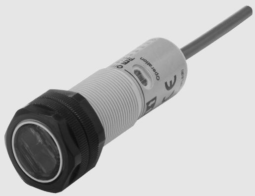
Cylindrical M18 photoelectric sensor for AC power supply
E3F2- Z
24 to 240 VAC power supply
- UL and CSA approved
C E
Selection Guide
Housing material: Plastic
| Sensing method | Appearance | Connection | Sensing | Model | ||
| method | distance | Light-ON | Dark-ON | |||
| Through-beam | axial | pre-wired | 3 m | E3F2-3Z1 | E3F2-3Z2 | |
| Retro-reflective | Non-polarizing (without MSR function) | axial | pre-wired | 0.1 - 2 m (with reflector E39-R1) | E3F2-R2Z1-E | E3F2-R2Z2-E |
| Diffuse reflective | Fixed sensing distance Wide-beam characteristics | axial | pre-wired | 0.1 m | E3F2-DS10Z1-N | E3F2-DS10Z2-N |
Note: Standard cable length is 2 m. Models provided with a 5 m long cable are available. When ordering, specify the cable length by adding the length of the cable (e.g. E3F2-R2Z1 2M or E3F2-R2Z1 5M). For other cable length please contact your OMRON sales representative.
Ordering Information: type list
| Model | Sensing method, sensing range | Appearance | Connection (cable-length) | Control output | Comments |
| E3F2-3LZ 2M | Through-beam, 3 m | axial | Pre-wired (2 m)* | N.A. | Emitter only |
| E3F2-3DZ1 2M | Through-beam, 3 m | axial | Pre-wired (2 m)* | Light-ON | Receiver only |
| E3F2-3DZ2 2M | Through-beam, 3 m | axial | Pre-wired (2 m)* | Dark-ON | Receiver only |
| E3F2-3Z1 2M | Through-beam, 3 m | axial | Pre-wired (2 m)* | Light-ON | Receiver and Emitter |
| E3F2-3Z2 2M | Through-beam, 3 m | axial | Pre-wired (2 m)* | Dark-ON | Receiver and Emitter |
| E3F2-R2Z1 2M | Retroreflective, 2 m | axial | Pre-wired (2 m)* | Light-ON | Non-polarizing, incl. E39-R1 |
| E3F2-R2Z2 2M | Retroreflective, 2 m | axial | Pre-wired (2 m)* | Dark-ON | Non-polarizing, incl. E39-R1 |
| E3F2-R2Z1-E 2M | Retroreflective, 2 m | axial | Pre-wired (2 m)* | Light-ON | Non-polarizing, including reflector |
| E3F2-R2Z2-E 2M | Retroreflective, 2 m | axial | Pre-wired (2 m)* | Dark-ON | Non-polarizing, including reflector |
| E3F2-DS10Z1-N 2M | Diffuse reflective, 0.1 m | axial | Pre-wired (2 m)* | Light-ON | Wide-beam characteristic |
| E3F2-DS10Z2-N 2M | Diffuse reflective, 0.1 m | axial | Pre-wired (2 m)* | Dark-ON | Wide-beam characteristic |
- Standard cable length is 2 m. Models provided with a 5 m long cable are available. When ordering, specify the cable length by adding the length of the cable (e.g. E3F2-R2Z1 2M or E3F2-R2Z1 5M). For other cable length please contact your OMRON sales representative.
Ratings / Characteristics of AC Switching Models
| Item | E3F2-3Z1 E3F2-3Z2 | E3F2-R2Z1 E3F2-R2Z2 | E3F2-DS10Z1 E3F2-DS10Z2 |
| Sensing method | Through-beam | Non-polarizing Retroreflective | Diffuse reflective (wide-beam characteristic) |
| Power supply voltage | 24 to 240 VAC ±10%, 50/60 Hz | ||
| Current consumption | 10 mA max. | 5 mA max. | |
| Rated sensing distance *1 | 3 m | 0.1 - 2 m (with reflector E39-R1) | 0.1 m (5 x 5 cm white mat paper) |
| Typical sensing distance for dif-ferent reflector types *2 | - | E39-R1: 3,4 m E39-R7: 3,9 m E39-R8: 5,2 m | - |
| Detectable object | Opaque object: 11 mm min. | Opaque object: 56 mm min. | Opaque objects |
| Directional angle | 3° to 20° | - | |
| Differential travel | - | 20% max. | |
| Response time | 30 ms max. | ||
| Control output | AC solid state (SCR) 200 mA max.; residual voltage: 5 V max. at 200 mA | ||
| Power reset time | 100 ms | ||
| Ambient illumination | Incandescent lamp: 3000 lx max. Sunlight: 10000 lx max. | ||
| Ambient temperature *3 | Operating: -25 to 55 °C / Storage: -30 to 70 °C (with no icing or condensation) | ||
| Ambient humidity | Operating: 35% to 85% / Storage: 35% to 95% (without condensation) | ||
| Insulation resistance | 20 M min. at 500 V DC between energized parts and case | ||
| Dielectric strength | 1500 VAC, 50/60 Hz for 1 min between energized parts and case | ||
| Vibration resistance | 10 to 55 Hz, 1.5 mm double amplitude for 2 hrs each direction (X, Y, Z) | ||
| Shock resistance | 500 m/sqr (approx. 50 g) for each direction (X, Y, Z) | ||
| Enclosure rating | IP67 *4; NEMA 1, 2, 4; IP69k after DIN 40050 part 9 | ||
| Light source | Infrared LED (880 nm) | ||
| Indicators | Light incident/power indicator for light source (red) | ||
| Sensitivity adjustment | Fixed | ||
| Connection method | 2 m, 5 m pre-wired cable (PVC dia. 4 mm (14/0.15) *5) | ||
| Operation mode | Light-ON or Dark-ON (fixed) | ||
| Circuit protection | None | ||
| Weight (approx.) | 110 g (pre-wired 2 m cable) | ||
| Housing materials | Plastic (case: ABS; lens: PMMA) | ||
1 For stable sensing distance in detail, please refer to "Engineering Data"
Typical sensing distance corresponds to 80% of the max. sensing distance.
3
*4 The enclosure rating IP67 of OMRON internal standards correspond to stricter test requirements than the standard IEC 60529 (refer to chapter "Precautions")
*5 For other cable materials (e.g. PUR) please contact your OMRON sales representative.
Operating Range (typical)
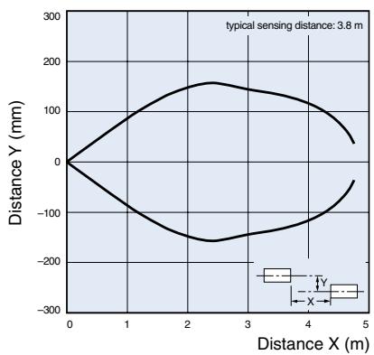
Through-beam Models (axial) E3F2-3Z
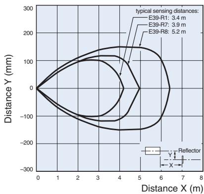
Retroreflective Models (axial) E3F2-R2Z (non polarizing) and reflectors
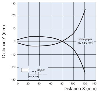
Diffuse reflective Models (axial) E3F2-DS10Z- wide-beam type
Excess Gain Ratio vs. Distance (typical)
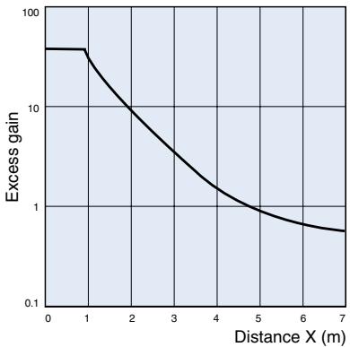
Through-beam Models (axial) E3F2-3Z
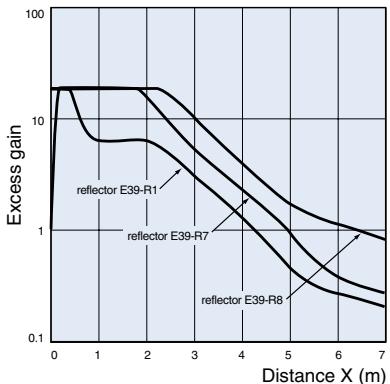
Retroreflective Models (axial) E3F2-R2Z (non polarizing) and reflectors
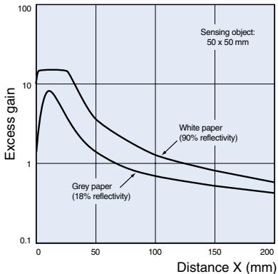
Diffuse reflective Models (axial) E3F2-DS10Z- wide-beam type
Operation
| Model | Output transistor status | Timing chart | Connection method | Output circuit | |
| E3F2-3LZ | - | - | - | Through-beam emitter Power indicator (red) Main circuit 24 to 240 VAC Blue | |
| E3F2-3Z1 E3F2-R2Z1 E3F2-DS10Z1-N | ON when light is incident. (Light-ON) | Incident Interrupted Output indicator (red) Output transistor Load (relay) | ON OFF ON OFF | - | Light indicator Red Main circuit 200 mA max. Black Load 24 to 240 VAC Blue |
| E3F2-3Z2 E3F2-R2Z2 E3F2-DS10Z2-N | ON when light is interrupted. (Dark-ON) | Incident Interrupted Output indicator (red) Output transistor Load (relay) | ON OFF ON OFF | - | |
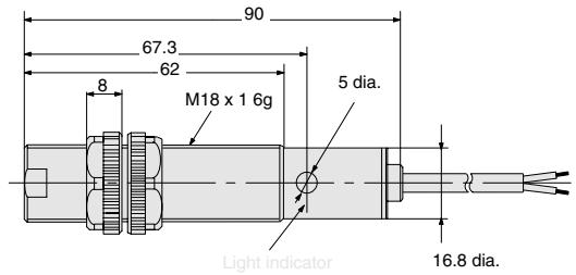
Cable type
Without potentiometer
E3F2-3Z
E3F2-R2Z
E3F2-DS10Z□-N
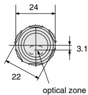
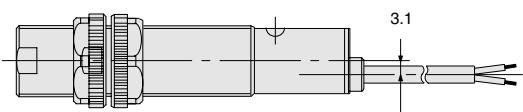
Precautions
The E3F2 Photoelectric Sensor is not a safety component for ensuring the safety of people which is defined in EC directive (91/368/EEC) and covered by separate European standards or by any other regulations or standards.
Degree of protection
The E3F2 photoelectric sensors have a degree of protection rated with IP67. In this case, the sensors have passed the OMRON heat shock test before the IP67-test of IEC 60529 (submersion at 1m water depth for 30min ). Afterwards the sensors have been tested according to the OMRON waterproof test.
Heat shock: Alternating, fast temperature changes between -25^ and +55^ are executed for 5 cycles and 1 hour for each temperature. Function and isolation are checked.
Water proof: The sensors are submerged alternating in water of +2^ and +55^ . 20 cycles with 1 hour for each temperature are executed. Function, water tightness and electrical isolation are checked.
Do not expose the photoelectric sensor to excessive shock during installation, keeping within IP 67 standards.
Wiring
If the input/output lines of the photoelectric sensor are placed in the same conduit or duct as power lines or high-voltage lines, the photoelectric sensor could be induced to malfunction, or even be damaged by electrical noise. Separate the wiring, or use shielded lines as input/output lines to the photoelectric sensor.
Do not connect the black wire to the brown wire without a load. Direct connection of these wires may damage the photoelectric sensor (AC switching type).
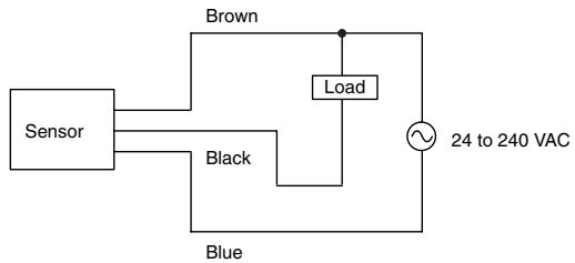
When using the photoelectric sensor in the vicinity of an inverter motor, ensure to connect the protective earth ground wire of the motor to earth. Failure to ground the motor may result in malfunction of the sensor.
When you use the photoelectric sensor at temperatures exceeding 45^ , the load current must be within the described values as shown in the figure below.
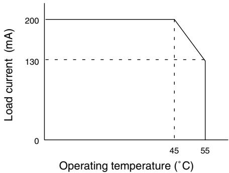
Installation
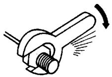
Do not exceed a torque of
- 2.0 Nm (20 kgf cm) when tightening mounting nuts for plastic models
- 20.0 Nm (200 kgf cm) when tightening mounting nuts for metal models
Cat. No. E43E-EN-01
In the interest of product improvement, specifications are subject to change without notice.
OMRON EUROPE B.V.
Wegalaan 67-69,
NL-2132 JD, Hoofddorp,
The Netherlands
Phone: +31 23 568 13 00
Fax: +31 23 568 13 88
www.eu.omron.com
Marque : OMRON
Modèle : E3F2-Z
Catégorie : Capteur de proximité