
E32-D82F - Capteurs de proximité OMRON - Notice d'utilisation et mode d'emploi gratuit
Retrouvez gratuitement la notice de l'appareil E32-D82F OMRON au format PDF.


| Type de produit | Capteur de niveau de fluide (contact) pour réservoir de lavage |
| Référence | E32-D82F (variantes E32-D82F1 et E32-D82F2) |
| Marque | OMRON |
| Catégorie | Capteurs de proximité |
| Principe de détection | Diffus-réfléchissant (fibre optique) |
| Matériau de la sonde | Téflon (PFA) – excellente résistance chimique et à l'huile |
| Plage de température de fonctionnement (partie téflon) | -40 °C à +200 °C (sans givrage ni condensation) |
| Plage de température (autres parties) | -40 °C à +85 °C |
| Humidité ambiante de fonctionnement | 35 % à 85 % HR |
| Pression périphérique de fonctionnement | -50 kPa à 500 kPa |
| Indice de protection | IP68 (norme IEC, partie téflon uniquement) |
| Poids (emballé) | Environ 75 g |
| Dimensions (E32-D82F1) | Longueur sans pliage : 150 mm à partir de l'extrémité |
| Dimensions (E32-D82F2) | Longueur sans pliage : 350 mm à partir de l'extrémité |
| Rayon de courbure admissible | 40 mm minimum (25 mm pour la partie en plastique) |
| Objet de détection standard | Eau pure à 25 °C |
| Distance différentielle | 3 mm max. |
| Précision de répétition | 0,5 mm ou moins (dans l'eau pure) |
| Angle d'inclinaison admissible de l'objet | ±10° ou moins |
| Accessoires fournis | Coupe-fibre |
| Fonctionnalités principales | Détection de niveau de fluide à haute précision ; mécanisme anti-goutte ; adapté aux fluides à haute température (acide sulfurique) |
| Entretien et nettoyage | Éviter les chocs sur l'extrémité du capteur ; ne pas utiliser si des bulles ou précipités adhèrent au cône |
| Sécurité | Utiliser uniquement la partie fibre en zone dangereuse ; placer l'amplificateur en zone sûre |
| Réparabilité | Pièces détachées non spécifiées ; consulter le service OMRON |
FOIRE AUX QUESTIONS - E32-D82F OMRON
Questions des utilisateurs sur E32-D82F OMRON
0 question sur cet appareil. Repondez a celles que vous connaissez ou posez la votre.
Poser une nouvelle question sur cet appareil
Téléchargez la notice de votre Capteurs de proximité au format PDF gratuitement ! Retrouvez votre notice E32-D82F - OMRON et reprennez votre appareil électronique en main. Sur cette page sont publiés tous les documents nécessaires à l'utilisation de votre appareil E32-D82F de la marque OMRON.
MODE D'EMPLOI E32-D82F OMRON
Fluid level sensor (contact type)
E32-D82F
High-accuracy detection of fluid level in washing tank.
- Uses Teflon (PFA) with excellent chemical and oil resistance.
- Capable of detecting high-temperature fluids such as sulfuric acid in a wafer washing tank. (-40 to +200°C)
- Achieves a high repetition precision of 0.5 ~mm (in pure water).
- Employs a dripping prevention mechanism.

Ordering Information
Fiber Units
| Sensor type | Shape | Model | Remarks |
| Diffuse-reflective | E32-D82F1 | Length of no-bending section: 150 mm from tip | |
| E32-D82F2 | Length of no-bending section: 350 mm from tip |
Applicable amplifier unit
| Model |
| E3X-DA-N |
| E3X-NA |
Rating/performance
| Sensor type Item | Model | Diffuse-reflective | |
| E32-D82F1 | E32-D82F2 | ||
| Standard sensing object | Pure water at 25°C | ||
| Differential distance | 3 mm max. | ||
| Repetition precision | 0.5 mm or less | ||
| Permissible angle of detection object inclination | ±10° or less | ||
| Perim- eter | Teflon section within 1.5 m of fiber tip*1 | Operating: -40 to +200°C, Storage: -40°C to +85°C (with no icing or condensation) | |
| Tem- pera- ture | Parts other than the above | Operating/storage: -40 to +85°C (no ice formation or condensation) | |
| Ambient humidity | Operating/storage: 35 to 85% RH | ||
| Peripheral pressure | Operating: -50 kPa to 500 kPa | ||
| Admissible bending radius (10% under fluid level) | 40 mm or higher (25 mm for plastic fiber section) | ||
| average) | Length of no- bending section | 150 mm from tip | 350 mm from tip |
| Material | Sensor case | Teflon (PFA) | |
| Fiber cladding | Black polyethylene | ||
| Connector | Brass-nickel coating | ||
| Protective structure | IEC Standard IP68*2 | ||
| Weight (Packed state) | Approx. 75 g | ||
| Accessories | Fiber cutter | ||
1. Teflon is a registered trademark of Dupont Company and Mitsui Dupont Chemical Company for their fluoride resin.
2. Only applies to Teflon section; the standard requires no bubbling when air at 98kPa is injected for 30 seconds at a depth of 100mm in water.
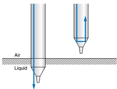
Principle of operation
- In air, the difference between the index of refraction of the Teflon section and that of air is larger, and the light is reflected by the detected surface and returns to the light receiver.
- In the fluid, there is almost no difference between the index of refraction of the Teflon section and that of the fluid, and the light radiates into the fluid.
Teaching type
1. Using teaching without work
Perform teaching with the tip of the fiber unit in the fluid. (The sensitivity is set to the top 10% of the received light intensity in fluid for stronger performance with respect to fluctuations in received light intensity due to fluid leakage, and thus teaching without work for high viscosity fluids is effective.)
2. Using teaching with/without work
Perform teaching after the object has been removed from the fluid, and then repeat teaching with the object in the fluid. (Teaching with/without work is effective for fluids in which bubbles form at high temperature.)
Note: If set to the maximum sensitivity with the object removed from the fluid, detection of the fluid will no longer be possible.
Sensitivity control type
| Sequence | Detection state | Sensitivity adjuster | Indicator state | Adjustment procedure | |
| 1 | (A)18 | Green | Red | Determine the position A at which the incident light indicator lamp (red) illuminates as the sensitivity control is gradually increased from the minimum setting after the object has been removed from the fluid. | |
| OFF | OFF | ||||
| 2 | (B)18 | Green | Red | • If the red indicator lamp illuminates at the maximum sensitivity setting, gradually decrease the sensitivity control from the maximum setting with the object in the fluid, and determine the position B at which the incident light indicator lamp (red) goes off. • If the red indicator lamp goes off at the maximum sensitivity | |
| OFF | OFF | ||||
| 3 | --- | (A)(C)18 | Green | Red | Set the sensitivity control to C midway between A and B. At this time, verify that the stability indicator lamp (green) illuminates both with and without fluid. |
| ON | OFF | ||||
Precautions
Correct Use
Installation
- Use the no-bending section to secure the fiber unit. If the fiber unit is secured without using the no-bending section, the fluid level detection position may shift.
- Influences from the sides or bottom may interfere with detection. In that case, remove to a distance that is not subject to these influences, or apply a black coating to the sides and bottom.
- If you need to use the system in a dangerous location, use only the fiber unit in the dangerous location and place the amplifier unit in a safe location.
For adjustment
About the fluid level detection position
The fluid level detection position is located 5.2 ± 2 mm from the tip of the Teflon section (see the diagram at right). The fluid level detection
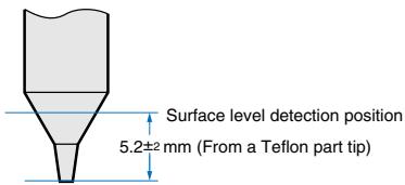
position will vary depending on the surface tension of the fluid and the dampness of the detection position of the fiber unit.
Miscellaneous
- Operation will not be stable in the following situations. ① Bubbles adhere to the cone of the detector head. ② Solutes have precipitated onto the cone of the detector head. ③ The fluid has a high viscosity.
- Some fluids such as those of a milky-white color may not permit detection.
- Take care not to strike the tip with any object. A damaged or deformed detector head may cause unstable operation.
Dimensions (Unit: mm)
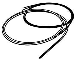
E32-D82F1 E32-D82F2

1. ( ): E32-D82F2 dimensions
2. Freely cut because 2m part of optical fiber at amplifier side is made from a plastic fiber.
ALL DIMENSIONS SHOWN ARE IN MILLIMETERS.
To convert millimeters into inches, multiply by 0.03937. To convert grams into ounces, multiply by 0.03527.
Cat. No. E41E-EN-01
In the interest of product improvement, specifications are subject to change without notice.
- Fluid level sensor (contact type)
- E32-D82F
- High-accuracy detection of fluid level in washing tank.
- Ordering Information
- Teaching type
- Using teaching without work
- Using teaching with/without work
- Sensitivity control type
- Precautions
- Correct Use
- Installation
- About the fluid level detection position
- Miscellaneous
- Dimensions (Unit: mm)
Marque : OMRON
Modèle : E32-D82F
Catégorie : Capteurs de proximité