
NBG-334W - Routeur sans fil ZYXEL - Notice d'utilisation et mode d'emploi gratuit
Retrouvez gratuitement la notice de l'appareil NBG-334W ZYXEL au format PDF.

| Type de produit | Routeur sans fil |
| Marque | ZYXEL |
| Modèle | NBG-334W |
| Dimensions (L x P x H) | 132 x 130 x 30 mm |
| Poids | 230 g |
| Alimentation | 12 V DC, 1 A |
| Normes sans fil | IEEE 802.11b/g |
| Bande de fréquence | 2,4 GHz |
| Débit maximal | 54 Mbps (802.11g) |
| Ports LAN | 4 ports Ethernet 10/100 Mbps |
| Port WAN | 1 port Ethernet 10/100 Mbps |
| Antenne | 1 antenne externe |
| Modes de fonctionnement | Routeur, Point d'accès |
| Fonctions de sécurité | WEP 64/128 bits, WPA-PSK, WPA2-PSK, Filtrage MAC, Pare-feu |
| DHCP | Serveur DHCP intégré |
| NAT | Translation d'adresses réseau (NAT) |
| Gestion de bande passante | Oui, par application ou sous-réseau |
| UPnP | Prise en charge |
| Configuration | Interface web (HTTP), Telnet, FTP |
| Garantie | 2 ans |
| Entretien | Nettoyer avec un chiffon doux et sec, ne pas utiliser de produits chimiques |
| Accessoires inclus | Adaptateur secteur, câble Ethernet, guide de démarrage rapide, CD de support |
| Certifications | FCC, CE, ICES-003 |
FOIRE AUX QUESTIONS - NBG-334W ZYXEL
Questions des utilisateurs sur NBG-334W ZYXEL
0 question sur cet appareil. Repondez a celles que vous connaissez ou posez la votre.
Poser une nouvelle question sur cet appareil
Téléchargez la notice de votre Routeur sans fil au format PDF gratuitement ! Retrouvez votre notice NBG-334W - ZYXEL et reprennez votre appareil électronique en main. Sur cette page sont publiés tous les documents nécessaires à l'utilisation de votre appareil NBG-334W de la marque ZYXEL.
MODE D'EMPLOI NBG-334W ZYXEL
NBG334W
802.11g Wireless Firewall Router
User's Guide
Version 3.60
10/2007
Edition 2
DEFAULT LOGIN
IP Address http://192.168.1.1
User Name admin
Password 1234
About This User's Guide
Intended Audience
This manual is intended for people who want to configure the NBG334W using the web configurator. You should have at least a basic knowledge of TCP/IP networking concepts and topology.
Related Documentation
- Quick Start Guide
The Quick Start Guide is designed to help you get up and running right away. It contains information on setting up your network and configuring for Internet access.
• Web Configurator Online Help
Embedded web help for descriptions of individual screens and supplementary information.

It is recommended you use the web configurator to configure the NBG334W.
- Supporting Disk
Refer to the included CD for support documents. - ZyXEL Web Site
Please refer to www.zyxel.com for additional support documentation and product certifications.
User Guide Feedback
Help us help you. Send all User Guide-related comments, questions or suggestions for improvement to the following address, or use e-mail instead. Thank you!
The Technical Writing Team,
ZyXEL Communications Corp.,
6 Innovation Road II,
Science-Based Industrial Park,
Hsinchu, 300, Taiwan.
E-mail: techwriters@zyxel.com.tw
Document Conventions
Warnings and Notes
These are how warnings and notes are shown in this User's Guide.

Warnings tell you about things that could harm you or your device.

Notes tell you other important information (for example, other things you may need to configure or helpful tips) or recommendations.
Syntax Conventions
- The NBG334W may be referred to as the “NBG334W”, the “device”, the “product” or the “system” in this User’s Guide.
- Product labels, screen names, field labels and field choices are all in bold font.
- A key stroke is denoted by square brackets and uppercase text, for example, [ENTER] means the “enter” or “return” key on your keyboard.
- “Enter” means for you to type one or more characters and then press the [ENTER] key. “Select” or “choose” means for you to use one of the predefined choices.
- A right angle bracket (>) within a screen name denotes a mouse click. For example, Maintenance > Log > Log Setting means you first click Maintenance in the navigation panel, then the Log sub menu and finally the Log Setting tab to get to that screen.
- Units of measurement may denote the “metric” value or the “scientific” value. For example, “k” for kilo may denote “1000” or “1024”, “M” for mega may denote “1000000” or “1048576” and so on.
- “e.g.,” is a shorthand for “for instance”, and “i.e.,” means “that is” or “in other words”.
Icons Used in Figures
Figures in this User's Guide may use the following generic icons. The NBG334W icon is not an exact representation of your device.
NBG334W | Computer | Notebook computer |
Server | DSLAM | Firewall |
Telephone | Switch | Router |
Modem | NBG334W |
Safety Warnings

For your safety, be sure to read and follow all warning notices and instructions.
- Do NOT use this product near water, for example, in a wet basement or near a swimming pool.
- Do NOT expose your device to dampness, dust or corrosive liquids.
- Do NOT store things on the device.
- Do NOT install, use, or service this device during a thunderstorm. There is a remote risk of electric shock from lightning.
- Connect ONLY suitable accessories to the device.
- Do NOT open the device or unit. Opening or removing covers can expose you to dangerous high voltage points or other risks. ONLY qualified service personnel should service or disassemble this device. Please contact your vendor for further information.
- Make sure to connect the cables to the correct ports.
- Place connecting cables carefully so that no one will step on them or stumble over them.
• Always disconnect all cables from this device before servicing or disassembling. - Use ONLY an appropriate power adaptor or cord for your device.
- Connect the power adaptor or cord to the right supply voltage (for example, 110V AC in North America or 230V AC in Europe).
- Do NOT allow anything to rest on the power adaptor or cord and do NOT place the product where anyone can walk on the power adaptor or cord.
- Do NOT use the device if the power adaptor or cord is damaged as it might cause electrocution.
- If the power adaptor or cord is damaged, remove it from the power outlet.
- Do NOT attempt to repair the power adaptor or cord. Contact your local vendor to order a new one.
- Do not use the device outside, and make sure all the connections are indoors. There is a remote risk of electric shock from lightning.
- Do NOT obstruct the device ventilation slots, as insufficient airflow may harm your device.
- Antenna Warning! This device meets ETSI and FCC certification requirements when using the included antenna(s). Only use the included antenna(s).
- If you wall mount your device, make sure that no electrical lines, gas or water pipes will be damaged.
This product is recyclable. Dispose of it properly.

Contents Overview
Introduction 29
Getting to Know Your NBG334W 31
Introducing the Web Configurator 35
Connection Wizard 47
AP Mode 63
Network 71
Wireless LAN 73
Wireless Tutorial 93
WAN 101
LAN 111
Guest WLAN 117
DHCP 123
Network Address Translation (NAT) 129
Dynamic DNS 139
Security 141
Firewall 143
Content Filtering 149
Management 153
Static Route Screens 155
Bandwidth Management 159
Remote Management 169
Universal Plug-and-Play (UPnP) 175
Maintenance and Troubleshooting 187
System 189
Logs 193
Tools 207
Configuration Mode 213
Sys Op Mode 215
Language 219
Troubleshooting 221
Appendices and Index 227
Table of Contents
About This User's Guide .... 3
Document Conventions....4
Safety Warnings....6
Contents Overview 9
Table of Contents......11
List of Figures 19
List of Tables 25
Part I: Introduction.... 29
Chapter 1 Getting to Know Your NBG334W....31
1.1 Overview ...... 31
1.2 AP Mode 31
1.3 Router Mode 32
1.4 Router Features vs. AP Features 32
1.5 Ways to Manage the NBG334W 33
1.6 Good Habits for Managing the NBG334W 33
1.7 LEDs 33
Chapter 2 Introducing the Web Configurator ....35
2.1 Web Configurator Overview 35
2.2 Accessing the Web Configurator 35
2.3 Resetting the NBG334W 37
2.3.1 Procedure to Use the Reset Button 37
2.4 Navigating the Web Configurator 37
2.5 The Status Screen in Router Mode 37
2.5.1 Navigation Panel 40
2.5.2 Summary: Any IP Table 43
2.5.3 Summary: Bandwidth Management Monitor 43
2.5.4 Summary: DHCP Table 43
2.5.5 Summary: Packet Statistics 44
2.5.6 Summary: Wireless Station Status 45
Chapter 3
Connection Wizard 47
3.1 Wizard Setup 47
3.2 Connection Wizard: STEP 1: System Information .... 48
3.2.1 System Name 48
3.2.2 Domain Name 49
3.3 Connection Wizard: STEP 2: Wireless LAN 49
3.3.1 Basic (WEP) Security 51
3.3.2 Extend (WPA-PSK or WPA2-PSK) Security 52
3.4 Connection Wizard: STEP 3: Internet Configuration 52
3.4.1 Ethernet Connection 53
3.4.2 PPPoE Connection 53
3.4.3 PPTP Connection 54
3.4.4 Your IP Address 56
3.4.5 WAN IP Address Assignment 56
3.4.6 IP Address and Subnet Mask 57
3.4.7 DNS Server Address Assignment 57
3.4.8 WAN IP and DNS Server Address Assignment 58
3.4.9 WAN MAC Address 59
3.5 Connection Wizard: STEP 4: Bandwidth management 60
3.6 Connection Wizard Complete 60
Chapter 4
AP Mode....63
4.1 AP Mode Overview 63
4.2 Setting your NBG334W to AP Mode 63
4.3 The Status Screen in AP Mode 64
4.3.1 Navigation Panel 66
4.4 Configuring Your Settings 67
4.4.1 LAN Settings 67
4.4.2 WLAN and Maintenance Settings 68
4.5 Logging in to the Web Configurator in AP Mode 68
Part II: Network....71
Chapter 5
Wireless LAN....73
5.1 Wireless Network Overview 73
5.2 Wireless Security Overview 75
5.2.1 SSID 75
5.2.2 MAC Address Filter 75
5.2.3 User Authentication 76
5.2.4 Encryption 76
5.3 Roaming 77
5.3.1 Requirements for Roaming 78
5.4 Quality of Service 78
5.4.1 WMM QoS 79
5.5 General Wireless LAN Screen 79
5.5.1 No Security 81
5.5.2 WEP Encryption 81
5.5.3 WPA-PSK/WPA2-PSK 83
5.5.4 WPA/WPA2 84
5.6 MAC Filter 86
5.7 Wireless LAN Advanced Screen 86
5.8 Quality of Service (QoS) Screen 88
5.8.1 Application Priority Configuration 89
5.9 WiFi Protected Setup 90
5.9.1 WPS Screen 90
5.9.2 WPS Station Screen 91
Chapter 6 Wireless Tutorial ......93
6.1 How to Connect to the Internet from an AP 93
6.2 Configure Wireless Security Using WPS on both your NBG334W and Wireless Client ..... 93
6.2.1 Push Button Configuration (PBC) 94
6.2.2 PIN Configuration 95
6.3 Enable and Configure Wireless Security without WPS on your NBG334W 96
6.4 Configure Your Notebook 98
Chapter 7 WAN....101
7.1 WAN Overview 101
7.2 WAN MAC Address 101
7.3 Multicast 101
7.4 Internet Connection 102
7.4.1 Ethernet Encapsulation 102
7.4.2 PPPoE Encapsulation 103
7.4.3 PPTP Encapsulation 106
7.5 Advanced WAN Screen 109
Chapter 8 LAN....111
8.1 LAN Overview ...... 111
8.1.1 IP Pool Setup 111
8.1.2 System DNS Servers 111
8.2 LAN TCP/IP 111
8.2.1 Factory LAN Defaults 111
8.2.2 IP Address and Subnet Mask 112
8.2.3 Multicast 112
8.2.4 Any IP 112
8.3 LAN IP Screen 114
8.4 LAN IP Alias 114
8.5 Advanced LAN Screen 115
Chapter 9
Guest WLAN 117
9.1 General Guest WLAN Screen 118
9.2 Guest WLAN MAC Filter 118
9.3 Guest WLAN IP Screen 119
9.4 Guest WLAN Bandwidth Screen 120
Chapter 10
DHCP 123
10.1 DHCP 123
10.2 DHCP Server General Screen 123
10.3 DHCP Server Advanced Screen 124
10.4 Client List Screen 126
Chapter 11
Network Address Translation (NAT)...... 129
11.1 NAT Overview 129
11.2 Using NAT 129
11.2.1 Port Forwarding: Services and Port Numbers 129
11.2.2 Configuring Servers Behind Port Forwarding Example 130
11.3 General NAT Screen 130
11.4 NAT Application Screen 131
11.4.1 Game List Example 133
11.5 Trigger Port Forwarding 134
11.5.1 Trigger Port Forwarding Example 134
11.5.2 Two Points To Remember About Trigger Ports 135
11.6 NAT Advanced Screen 135
Chapter 12
Dynamic DNS 139
12.1 Dynamic DNS Introduction 139
12.1.1 DynDNS Wildcard 139
12.2 Dynamic DNS Screen 139
Part III: Security.... 141
Chapter 13
Firewall....143
13.1 Introduction to ZyXEL's Firewall 143
13.1.1 What is a Firewall? 143
13.1.2 Stateful Inspection Firewall 143
13.1.3 About the NBG334W Firewall 143
13.1.4 Guidelines For Enhancing Security With Your Firewall 144
13.2 Triangle Routes 144
13.2.1 Triangle Routes and IP Alias 144
13.3 General Firewall Screen 145
13.4 Services Screen 146
Chapter 14
Content Filtering 149
14.1 Introduction to Content Filtering 149
14.2 Restrict Web Features 149
14.3 Days and Times 149
14.4 Filter Screen 149
14.5 Schedule 151
14.6 Customizing Keyword Blocking URL Checking 152
14.6.1 Domain Name or IP Address URL Checking 152
14.6.2 Full Path URL Checking 152
14.6.3 File Name URL Checking 152
Part IV: Management.... 153
Chapter 15
Static Route Screens 155
15.1 Static Route Overview 155
15.2 IP Static Route Screen 155
15.2.1 Static Route Setup Screen 156
Chapter 16
Bandwidth Management....159
16.1 Bandwidth Management Overview 159
16.2 Application-based Bandwidth Management 159
16.3 Subnet-based Bandwidth Management 159
16.4 Application and Subnet-based Bandwidth Management 160
16.5 Bandwidth Management Priorities ...... 160
16.6 Predefined Bandwidth Management Services ...... 161
16.6.1 Services and Port Numbers 162
16.7 Default Bandwidth Management Classes and Priorities .... 164
16.8 Bandwidth Management General Configuration 165
16.9 Bandwidth Management Advanced Configuration 165
16.9.1 Rule Configuration 167
16.10 Bandwidth Management Monitor 168
Chapter 17
Remote Management....169
17.1 Remote Management Overview 169
17.1.1 Remote Management Limitations ...... 169
17.1.2 Remote Management and NAT 170
17.1.3 System Timeout 170
17.2 WWW Screen 170
17.3 Telnet 171
17.4 Telnet Screen 171
17.5 FTP Screen 172
17.6 DNS Screen 173
Chapter 18
Universal Plug-and-Play (UPnP)....175
18.1 Introducing Universal Plug and Play 175
18.1.1 How do I know if I'm using UPnP? 175
18.1.2 NAT Traversal 175
18.1.3 Cautions with UPnP 175
18.2 UPnP and ZyXEL 176
18.3 UPnP Screen 176
18.4 Installing UPnP in Windows Example 177
Part V: Maintenance and Troubleshooting 187
Chapter 19
System 189
19.1 System Overview ...... 189
19.2 System General Screen 189
19.3 Time Setting Screen 190
Chapter 20
Logs 193
20.1 View Log 193
20.2 Log Settings 194
20.3 Log Descriptions 197
Chapter 21
Tools....207
21.1 Firmware Upload Screen 207
21.2 Configuration Screen 208
21.2.1 Backup Configuration 209
21.2.2 Restore Configuration 209
21.2.3 Back to Factory Defaults 210
21.3 Restart Screen 210
Chapter 22
Configuration Mode 213
Chapter 23
Sys Op Mode 215
23.1 Overview 215
23.1.1 Router 215
23.1.2 AP 215
23.2 Selecting System Operation Mode 216
Chapter 24
Language 219
24.1 Language Screen 219
Chapter 25
Troubleshooting....221
25.1 Power, Hardware Connections, and LEDs 221
25.2 NBG334W Access and Login 222
25.3 Internet Access 224
25.4 Resetting the NBG334W to Its Factory Defaults 225
25.5 Wireless Router/AP Troubleshooting 225
25.6 Advanced Features 226
Part VI: Appendices and Index 227
Appendix A Product Specifications and Wall-Mounting Instructions 229
Appendix B Pop-up Windows, JavaScripts and Java Permissions 235
Appendix C IP Addresses and Subnetting 241
Appendix D Setting up Your Computer's IP Address 249
25.6.1 Verifying Settings 264
Appendix E Wireless LANs 265
25.6.2 WPA(2)-PSK Application Example 274
25.6.3 WPA(2) with RADIUS Application Example 274
Appendix F Services 277
Appendix G Legal Information....281
Appendix H Customer Support....285
Index 291
List of Figures
Figure 1 Wireless Internet Access in AP Mode 31
Figure 2 Secure Wireless Internet Access in Router Mode 32
Figure 3 Front Panel 33
Figure 4 Change Password Screen 36
Figure 5 Web Configurator Status Screen 38
Figure 6 Any IP Table 43
Figure 7 Summary: BW MGMT Monitor 43
Figure 8 Summary: DHCP Table 44
Figure 9 Summary: Packet Statistics 44
Figure 10 Summary: Wireless Association List 45
Figure 11 Select Wizard or Advanced Mode 47
Figure 12 Select a Language ....48
Figure 13 Welcome to the Connection Wizard .... 48
Figure 14 Wizard Step 1: System Information .... 49
Figure 15 Wizard Step 2: Wireless LAN 50
Figure 16 Wizard Step 2: Basic (WEP) Security .... 51
Figure 17 Wizard Step 2: Extend (WPA-PSK or WPA2-PSK) Security 52
Figure 18 Wizard Step 3: ISP Parameters. 53
Figure 19 Wizard Step 3: Ethernet Connection .... 53
Figure 20 Wizard Step 3: PPPoE Connection .... 54
Figure 21 Wizard Step 3: PPTP Connection .... 55
Figure 22 Wizard Step 3: Your IP Address 56
Figure 23 Wizard Step 3: WAN IP and DNS Server Addresses .... 58
Figure 24 Wizard Step 3: WAN MAC Address 59
Figure 25 Wizard Step 4: Bandwidth Management 60
Figure 26 Connection Wizard Save 61
Figure 27 Connection Wizard Complete 61
Figure 28 Wireless Internet Access in AP Mode 63
Figure 29 Maintenance > Sys OP Mode > General 64
Figure 30 Status: AP Mode 64
Figure 31 Menu: AP Mode 66
Figure 32 Network > LAN > IP 68
Figure 33 Example of a Wireless Network ...... 73
Figure 34 Roaming Example 78
Figure 35 Network > Wireless LAN > General 80
Figure 36 Network > Wireless LAN > General: No Security 81
Figure 37 Network > Wireless LAN > General: Static WEP 82
Figure 38 Network > Wireless LAN > General: WPA-PSK/WPA2-PSK 83
Figure 39 Network > Wireless LAN > General: WPA/WPA2 84
Figure 40 Network > Wireless LAN > MAC Filter 86
Figure 41 Network > Wireless LAN > Advanced 87
Figure 42 Network > Wireless LAN > QoS 88
Figure 43 Network > Wireless LAN > QoS: Application Priority Configuration 89
Figure 44 WPS 91
Figure 45 WPS Station 92
Figure 46 Wireless AP Connection to the Internet 93
Figure 47 Example WPS Process: PBC Method 95
Figure 48 Example WPS Process: PIN Method 96
Figure 49 Network > Wireless LAN > General 97
Figure 50 Status: AP Mode 98
Figure 51 Connecting a Wireless Client to a Wireless Network t 99
Figure 52 Security Settings 99
Figure 53 Confirm Save 99
Figure 54 Link Status .... 100
Figure 55 Network > WAN > Internet Connection: Ethernet Encapsulation .... 102
Figure 56 Network > WAN > Internet Connection: PPPoE Encapsulation 104
Figure 57 Network > WAN > Internet Connection: PPTP Encapsulation 107
Figure 58 Network > WAN > Advanced 109
Figure 59 Any IP Example ......113
Figure 60 Network > LAN > IP ....114
Figure 61 Network > LAN > IP Alias ....115
Figure 62 Network > LAN > Advanced 115
Figure 63 Guest Wireless LAN Network ....117
Figure 64 Network > Guest WLAN > General 118
Figure 65 Network > Guest WLAN > MAC Filter 119
Figure 66 Network > Guest WLAN > IP 120
Figure 67 Example: Bandwidth for Different Networks .... 120
Figure 68 Network > Guest WLAN > Bandwidth 121
Figure 69 Network > DHCP Server > General 123
Figure 70 Network > DHCP Server > Advanced 125
Figure 71 Network > DHCP Server > Client List 127
Figure 72 Multiple Servers Behind NAT Example 130
Figure 73 Network > NAT > General 130
Figure 74 Network > NAT > Application 132
Figure 75 Game List Example 134
Figure 76 Trigger Port Forwarding Process: Example 135
Figure 77 Network > NAT > Advanced 136
Figure 78 Dynamic DNS 140
Figure 79 Using IP Alias to Solve the Triangle Route Problem 145
Figure 80 Security > Firewall > General I 145
Figure 81 Security > Firewall > Services 146
Figure 82 Security > Content Filter > Filter 150
Figure 83 Security > Content Filter > Schedule 151
Figure 84 Example of Static Routing Topology .... 155
Figure 85 Management > Static Route > IP Static Route .... 156
Figure 86 Management > Static Route > IP Static Route: Static Route Setup 157
Figure 87 Subnet-based Bandwidth Management Example 160
Figure 88 Management > Bandwidth MGMT > General 165
Figure 89 Management > Bandwidth MGMT > Advanced 166
Figure 90 Management > Bandwidth MGMT > Advanced: User-defined Service Rule Configuration 167
Figure 91 Management > Bandwidth MGMT > Monitor 168
Figure 92 Management > Remote MGMT > WWW 170
Figure 93 Telnet Configuration on a TCP/IP Network 171
Figure 94 Management > Remote MGMT > Telnet 171
Figure 95 Management > Remote MGMT > FTP 172
Figure 96 Management > Remote MGMT > DNS 173
Figure 97 Management > UPnP > General 176
Figure 98 Add/Remove Programs: Windows Setup: Communication 177
Figure 99 Add/Remove Programs: Windows Setup: Communication: Components .... 178
Figure 100 Network Connections .... 178
Figure 101 Windows Optional Networking Components Wizard .... 179
Figure 102 Networking Services .... 179
Figure 103 Network Connections .... 180
Figure 104 Internet Connection Properties ...... 181
Figure 105 Internet Connection Properties: Advanced Settings 182
Figure 106 Internet Connection Properties: Advanced Settings: Add 182
Figure 107 System Tray Icon .... 183
Figure 108 Internet Connection Status .... 183
Figure 109 Network Connections ...... 184
Figure 110 Network Connections: My Network Places .... 185
Figure 111 Network Connections: My Network Places: Properties: Example 185
Figure 112 Maintenance > System > General 189
Figure 113 Maintenance > System > Time Setting 190
Figure 114 Maintenance > Logs > View Log 193
Figure 115 Maintenance > Logs > Log Settings 195
Figure 116 Maintenance > Tools > Firmware 207
Figure 117 Upload Warning 208
Figure 118 Network Temporarily Disconnected 208
Figure 119 Upload Error Message 208
Figure 120 Maintenance > Tools > Configuration 209
Figure 121 Configuration Restore Successful 210
Figure 122 Temporarily Disconnected ...... 210
Figure 123 Configuration Restore Error 210
Figure 124 Maintenance > Tools > Restart ....211
Figure 125 Maintenance > Config Mode > General 213
Figure 126 LAN and WAN IP Addresses in Router Mode 215
Figure 127 IP Address in AP Mode .... 216
Figure 128 Maintenance > Sys OP Mode > General 216
Figure 129 Maintenance > Sys Op Mode > General: Router 216
Figure 130 Maintenance > Sys Op Mode > General: AP 217
Figure 131 Language ...... 219
Figure 132 Wall-mounting Example ...... 233
Figure 133 Masonry Plug and M4 Tap Screw 233
Figure 134 Pop-up Blocker 235
Figure 135 Internet Options: Privacy 236
Figure 136 Internet Options: Privacy 237
Figure 137 Pop-up Blocker Settings 237
Figure 138 Internet Options: Security 238
Figure 139 Security Settings - Java Scripting 239
Figure 140 Security Settings - Java 239
Figure 141 Java (Sun) 240
Figure 142 Network Number and Host ID 242
Figure 143 Subnetting Example: Before Subnetting 244
Figure 144 Subnetting Example: After Subnetting 245
Figure 145 Windows 95/98/Me: Network: Configuration 250
Figure 146 Windows 95/98/Me: TCP/IP Properties: IP Address 251
Figure 147 Windows 95/98/Me: TCP/IP Properties: DNS Configuration 252
Figure 148 Windows XP: Start Menu 253
Figure 149 Windows XP: Control Panel 253
Figure 150 Windows XP: Control Panel: Network Connections: Properties 254
Figure 151 Windows XP: Local Area Connection Properties 254
Figure 152 Windows XP: Internet Protocol (TCP/IP) Properties 255
Figure 153 Windows XP: Advanced TCP/IP Properties 256
Figure 154 Windows XP: Internet Protocol (TCP/IP) Properties 257
Figure 155 Macintosh OS 8/9: Apple Menu 258
Figure 156 Macintosh OS 8/9: TCP/IP 258
Figure 157 Macintosh OS X: Apple Menu 259
Figure 158 Macintosh OS X: Network 260
Figure 159 Red Hat 9.0: KDE: Network Configuration: Devices 261
Figure 160 Red Hat 9.0: KDE: Ethernet Device: General 262
Figure 161 Red Hat 9.0: KDE: Network Configuration: DNS 262
Figure 162 Red Hat 9.0: KDE: Network Configuration: Activate 263
Figure 163 Red Hat 9.0: Dynamic IP Address Setting in ifconfig-eth0 263
Figure 164 Red Hat 9.0: Static IP Address Setting in ifconfig-eth0 263
Figure 165 Red Hat 9.0: DNS Settings in resolv.conf 264
Figure 166 Red Hat 9.0: Restart Ethernet Card 264
Figure 167 Red Hat 9.0: Checking TCP/IP Properties 264
Figure 168 Peer-to-Peer Communication in an Ad-hoc Network 265
Figure 169 Basic Service Set .... 266
Figure 170 Infrastructure WLAN 267
Figure 171 RTS/CTS 268
Figure 172 WPA(2)-PSK Authentication ...... 274
List of Tables
Table 1 Features Available in Router Mode vs. AP Mode 32
Table 2 Front Panel LEDs 33
Table 3 Status Screen Icon Key 38
Table 4 Web Configurator Status Screen 39
Table 5 Screens Summary 41
Table 6 Summary: DHCP Table 44
Table 7 Summary: Packet Statistics 45
Table 8 Summary: Wireless Association List 46
Table 9 Wizard Step 1: System Information .... 49
Table 10 Wizard Step 2: Wireless LAN 50
Table 11 Wizard Step 2: Basic (WEP) Security 51
Table 12 Wizard Step 2: Extend (WPA-PSK or WPA2-PSK) Security 52
Table 13 Wizard Step 3: ISP Parameters .... 53
Table 14 Wizard Step 3: PPPoE Connection 54
Table 15 Wizard Step 3: PPTP Connection .... 55
Table 16 Wizard Step 3: Your IP Address .... 56
Table 17 Private IP Address Ranges 56
Table 18 Wizard Step 3: WAN IP and DNS Server Addresses .... 58
Table 19 Example of Network Properties for LAN Servers with Fixed IP Addresses ....59
Table 20 Wizard Step 3: WAN MAC Address 59
Table 21 Wizard Step 4: Bandwidth Management 60
Table 22 Web Configurator Status Screen 65
Table 23 Screens Summary 66
Table 24 Network > LAN > IP 68
Table 25 Types of Encryption for Each Type of Authentication 76
Table 26 WMM QoS Priorities 79
Table 27 Network > Wireless LAN > General 80
Table 28 Wireless No Security 81
Table 29 Network > Wireless LAN > General: Static WEP 82
Table 30 Network > Wireless LAN > General: WPA-PSK/WPA2-PSK 83
Table 31 Network > Wireless LAN > General: WPA/WPA2 85
Table 32 Network > Wireless LAN > MAC Filter 86
Table 33 Network > Wireless LAN > Advanced 87
Table 34 Network > Wireless LAN > QoS 88
Table 35 WPS 91
Table 36 WPS Station 92
Table 37 Network > WAN > Internet Connection: Ethernet Encapsulation 103
Table 38 Network > WAN > Internet Connection: PPPoE Encapsulation 105
Table 39 Network > WAN > Internet Connection: PPTP Encapsulation 108
Table 40 WAN > Advanced ....110
Table 41 Network > LAN > IP ....114
Table 42 Network > LAN > IP Alias ....115
Table 43 Network > LAN > Advanced 116
Table 44 Network > Guest WLAN > General 118
Table 45 Network > Guest WLAN > MAC Filter ..... 119
Table 46 Network > Guest WLAN > IP 120
Table 47 Network > Guest WLAN > Bandwidth 121
Table 48 Network > DHCP Server > General 124
Table 49 Network > DHCP Server > Advanced 125
Table 50 Network > DHCP Server > Client List 127
Table 51 Network > NAT > General 131
Table 52 NAT Application 132
Table 53 Network > NAT > Advanced 136
Table 54 Dynamic DNS 140
Table 55 Security > Firewall > General 146
Table 56 Security > Firewall > Services 147
Table 57 Security > Content Filter > Filter 150
Table 58 Security > Content Filter > Schedule 151
Table 59 Management > Static Route > IP Static Route 156
Table 60 Management > Static Route > IP Static Route: Static Route Setup 157
Table 61 Application and Subnet-based Bandwidth Management Example 160
Table 62 Bandwidth Management Priorities 160
Table 63 Media Bandwidth Management Setup: Services 161
Table 64 Commonly Used Services ...... 163
Table 65 Bandwidth Management Priority with Default Classes 164
Table 66 Management > Bandwidth MGMT > General 165
Table 67 Management > Bandwidth MGMT > Advanced 166
Table 68 Management > Bandwidth MGMT > Advanced: User-defined Service Rule Configuration . 167
Table 69 Management > Remote MGMT > WWW 170
Table 70 Management > Remote MGMT > Telnet 172
Table 71 Management > Remote MGMT > FTP 172
Table 72 Management > Remote MGMT > DNS 173
Table 73 Management > UPnP > General 176
Table 74 Maintenance > System > General 189
Table 75 Maintenance > System > Time Setting 191
Table 76 Maintenance > Logs > View Log 194
Table 77 Maintenance > Logs > Log Settings 195
Table 78 System Maintenance Logs 197
Table 79 System Error Logs 198
Table 80 Access Control Logs 198
Table 81 TCP Reset Logs 198
Table 82 Packet Filter Logs ...... 199
Table 83 ICMP Logs 199
Table 84 CDR Logs 200
Table 85 PPP Logs 200
Table 86 UPnP Logs 200
Table 87 Content Filtering Logs ...... 200
Table 88 Attack Logs 201
Table 89 PKI Logs 202
Table 90 802.1X Logs 203
Table 91 ACL Setting Notes 204
Table 92 ICMP Notes ...... 204
Table 93 Syslog Logs 205
Table 94 RFC-2408 ISAKMP Payload Types 205
Table 95 Maintenance > Tools > Firmware 207
Table 96 Maintenance Restore Configuration 209
Table 97 Maintenance > Config Mode > General 213
Table 98 Advanced Configuration Options 214
Table 99 Maintenance > Sys OP Mode > General 217
Table 100 Hardware Features 229
Table 101 Firmware Features ...... 229
Table 102 Feature Specifications ...... 231
Table 103 Standards Supported 231
Table 104 Subnet Mask - Identifying Network Number 242
Table 105 Subnet Masks 243
Table 106 Maximum Host Numbers ...... 243
Table 107 Alternative Subnet Mask Notation ...... 243
Table 108 Subnet 1 245
Table 109 Subnet 2 246
Table 110 Subnet 3 246
Table 111 Subnet 4 246
Table 112 Eight Subnets 246
Table 113 24-bit Network Number Subnet Planning 247
Table 114 16-bit Network Number Subnet Planning 247
Table 115 IEEE 802.11g 269
Table 116 Comparison of EAP Authentication Types 272
Table 117 Wireless Security Relational Matrix 275
Table 118 Examples of Services ...... 277
PART I
Introduction
Getting to Know Your NBG334W (31)
Introducing the Web Configurator (35)
Connection Wizard (47)
AP Mode (63)
Getting to Know Your NBG334W
This chapter introduces the main features and applications of the NBG334W.
1.1 Overview
The NBG334W acts as either an access point (AP) or a secure broadband router for all data passing between the Internet and your local network. In both AP and Router Mode you can set up a wireless network with other IEEE 802.11b/g compatible devices. In Router Mode a number of services such as a firewall and content filtering are also available. You can use media bandwidth management to efficiently manage traffic on your network. Bandwidth management features allow you to prioritize time-sensitive or highly important applications such as Voice over the Internet (VoIP).
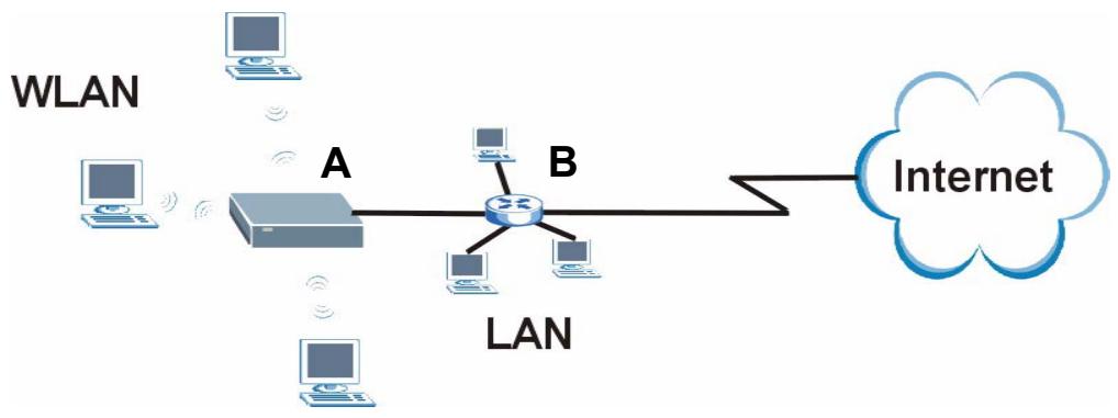
1.2 AP Mode
Select AP Mode if you already have a router or gateway on your network which provides network services such as a firewall or bandwidth management.
The following figure shows computers in a WLAN connecting to the NBG334W, which acts as an access point (A). The NBG334W allows the wireless computers to share the same Internet access as the other computers connected to the router (B) on the same network.
Figure 1 Wireless Internet Access in AP Mode
flowchart
graph TD
    A["Router A"] --> B["Router B"]
    B --> C["Internet"]
    subgraph WLAN
        D["Computer 1"]
        E["Computer 2"]
        F["Computer 3"]
        G["Computer 4"]
    end
    subgraph LAN
        H["Computer 5"]
        I["Computer 6"]
        J["Computer 7"]
    end
    A --> B
    B --> C
    style A fill:#ccc,stroke:#333
    style B fill:#ccc,stroke:#333
    style C fill:#fff,stroke:#333
    style D fill:#fff,stroke:#333
    style E fill:#fff,stroke:#333
    style F fill:#fff,stroke:#333
    style G fill:#fff,stroke:#333
    style H fill:#fff,stroke:#333
    style I fill:#fff,stroke:#333
    style J fill:#fff,stroke:#333
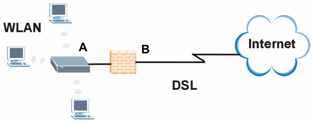
1.3 Router Mode
Select Router Mode if you need to route traffic between your network and another network such as the Internet, and require important network services such as a firewall or bandwidth management.
The following figure shows computers in a WLAN connecting to the NBG334W (A), which has a DSL connection to the Internet. The NBG334W is set to Router Mode and has router features such as a built-in firewall (B).
Figure 2 Secure Wireless Internet Access in Router Mode
flowchart
graph LR
    A["Router A"] -->|DSL| B["Brick Wall B"]
    B --> C["Internet"]
    D["WLAN"] --> A
    E["Computer"] --> A
    F["Computer"] --> A
1.4 Router Features vs. AP Features
The following table shows which features are available in Router or AP Mode.
Table 1 Features Available in Router Mode vs. AP Mode
| FEATURE | ROUTER MODE | AP MODE |
| DHCPThis allows individual clients to obtain IP addresses at start-up from a DHCP server. | YES | NO |
| FirewallThis establishes a network security barrier, protecting your network from attacks and controlling access between your network and the Internet. | YES | NO |
| Bandwidth ManagementThis allows you to allocate network bandwidth to specific applications and or subnets. | YES | NO |
| Any IPThis allows a computer to access the NBG334W when the IP addresses of the computer and the NBG334W are not in the same subnet.) | YES | NO |
| WirelessThis allows two or more devices to communicate without wires, based on IEEE 802.11 wireless standards. | YES | YES |
1.5 Ways to Manage the NBG334W
Use any of the following methods to manage the NBG334W.
- Web Configurator. This is recommended for everyday management of the NBG334W using a (supported) web browser.
- Command Line Interface. Line commands are mostly used for troubleshooting by service engineers.
- FTP. Use File Transfer Protocol for firmware upgrades and configuration backup/restore.
1.6 Good Habits for Managing the NBG334W
Do the following things regularly to make the NBG334W more secure and to manage the NBG334W more effectively.
- Change the password. Use a password that's not easy to guess and that consists of different types of characters, such as numbers and letters.
- Write down the password and put it in a safe place.
- Back up the configuration (and make sure you know how to restore it). Restoring an earlier working configuration may be useful if the device becomes unstable or even crashes. If you forget your password, you will have to reset the NBG334W to its factory default settings. If you backed up an earlier configuration file, you would not have to totally re-configure the NBG334W. You could simply restore your last configuration.
1.7 LEDs
Figure 3 Front Panel

The following table describes the LEDs.
Table 2 Front Panel LEDs
| LED | COLOR | STATUS | DESCRIPTION |
| POWER | Green | On | The NBG334W is receiving power and functioning properly. |
| Off | The NBG334W is not receiving power. | ||
LAN 1-4 | Green | On | The NBG334W has a successful 10MB Ethernet connection. |
| Blinking | The NBG334W is sending/receiving data. | ||
| Amber | On | The NBG334W has a successful 100MB Ethernet connection. | |
| Blinking | The NBG334W is sending/receiving data. | ||
| Off | The LAN is not connected. | ||
WAN | Green | On | The NBG334W has a successful 10MB WAN connection. |
| Blinking | The NBG334W is sending/receiving data. | ||
| Amber | On | The NBG334W has a successful 100MB Ethernet connection. | |
| Blinking | The NBG334W is sending/receiving data. | ||
| Off | The WAN connection is not ready, or has failed. | ||
WLAN | Green | On | The NBG334W is ready, but is not sending/receiving data through the wireless LAN. |
| Blinking | The NBG334W is sending/receiving data through the wireless LAN. | ||
| Off | The wireless LAN is not ready or has failed. | ||
WPS | WPS (WiFi Protected Setup) automatically sets up security on your wireless network. This function is currently unavailable. | ||
Introducing the Web Configurator
This chapter describes how to access the NBG334W web configurator and provides an overview of its screens.
2.1 Web Configurator Overview
The web configurator is an HTML-based management interface that allows easy setup and management of the NBG334W via Internet browser. Use Internet Explorer 6.0 and later or Netscape Navigator 7.0 and later versions or Safari 2.0 or later versions. The recommended screen resolution is 1024 by 768 pixels.
In order to use the web configurator you need to allow:
- Web browser pop-up windows from your device. Web pop-up blocking is enabled by default in Windows XP SP (Service Pack) 2.
- JavaScripts (enabled by default).
- Java permissions (enabled by default).
Refer to the Troubleshooting chapter to see how to make sure these functions are allowed in Internet Explorer.
2.2 Accessing the Web Configurator
1 Make sure your NBG334W hardware is properly connected and prepare your computer or computer network to connect to the NBG334W (refer to the Quick Start Guide).
2 Launch your web browser.
3 Type "http://192.168.1.1" as the website address.
Your computer must be in the same subnet in order to access this website address.
- In Router Mode enable the DHCP Server. The NBG334W assigns your computer an IP address on the same subnet.
- In AP Mode the NBG334W does not assign an IP address to your computer, so you should check it's in the same subnet. See Section 4.5 on page 68 for more information.
4 Type "1234" (default) as the password and click Login. In some versions, the default password appears automatically - if this is the case, click Login.
5 You should see a screen asking you to change your password (highly recommended) as shown next. Type a new password (and retype it to confirm) and click Apply or click Ignore.
Figure 4 Change Password Screen
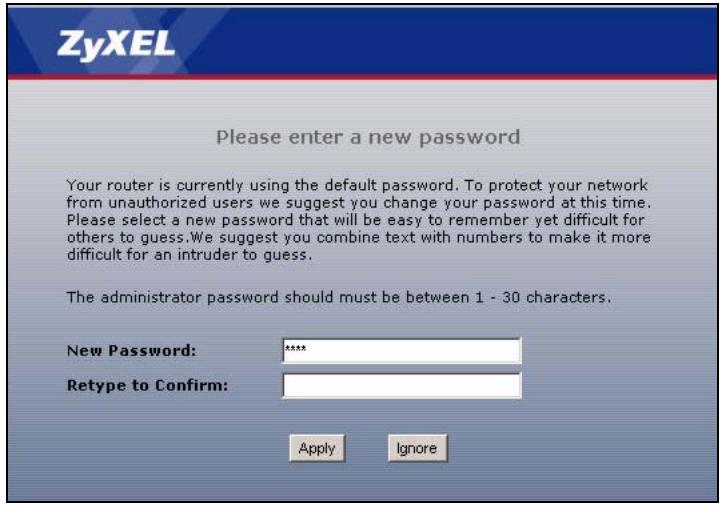

The management session automatically times out when the time period set in the Administrator Inactivity Timer field expires (default five minutes). Simply log back into the NBG334W if this happens.
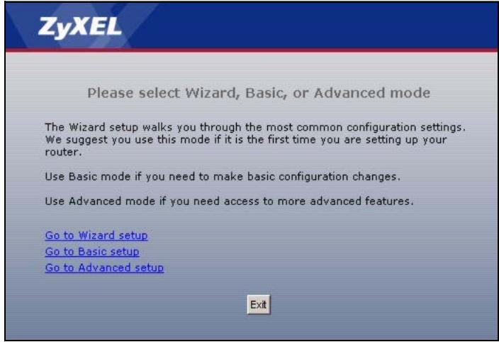
6 Select the setup mode you want to use.
- Click Go to Wizard Setup to use the Configuration Wizard for basic Internet and Wireless setup.
- Click Go to Basic Setup if you want to view and configure basic settings that are not part of the wizard setup. Not all Web Configurator screens are available in this mode. See Chapter 22 on page 213 for more information.
7 Click Go to Advanced Setup to view and configure all the NBG334W's settings.
2.3 Resetting the NBG334W
If you forget your password or IP address, or you cannot access the web configurator, you will need to use the RESET button at the back of the NBG334W to reload the factory-default configuration file. This means that you will lose all configurations that you had previously saved, the password will be reset to “1234” and the IP address will be reset to “192.168.1.1”.
2.3.1 Procedure to Use the Reset Button
1 Make sure the power LED is on.
2 Press the RESET button for five seconds or until the power LED begins to blink and then release it. When the power LED begins to blink, the defaults have been restored and the NBG334W restarts.
2.4 Navigating the Web Configurator
The following summarizes how to navigate the web configurator from the Status screen in Router Mode and AP Mode.
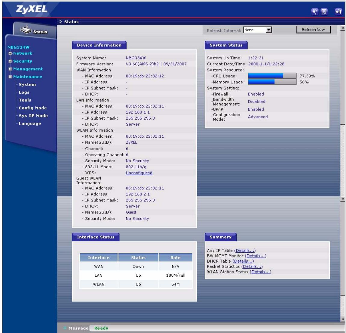
2.5 The Status Screen in Router Mode
Click on Status. The screen below shows the status screen in Router Mode. (For information on the status screen in AP Mode see Chapter 4 on page 64.)
Figure 5 Web Configurator Status Screen
The following table describes the icons shown in the Status screen.
Table 3 Status Screen Icon Key
| ICON | DESCRIPTION |
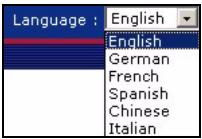 | Select a language from the drop-down list box to have the web configurator display in that language. |
 | Click this icon to open the setup wizard. |
 | Click this icon to view copyright and a link for related product information. |
 | Click this icon at any time to exit the web configurator. |
| Select a number of seconds or None from the drop-down list box to refresh all screen statistics automatically at the end of every time interval or to not refresh the screen statistics. | |
| Click this button to refresh the status screen statistics. |
The following table describes the labels shown in the Status screen.
Table 4 Web Configurator Status Screen
| LABEL | DESCRIPTION |
| Device Information | |
| System Name | This is the System Name you enter in the Maintenance > System > General screen. It is for identification purposes. |
| Firmware Version | This is the firmware version and the date created. |
| WAN Information | |
| - MAC Address | This shows the WAN Ethernet adapter MAC Address of your device. |
| - IP Address | This shows the WAN port's IP address. |
| - IP Subnet Mask | This shows the WAN port's subnet mask. |
| - DHCP | This shows the WAN port's DHCP role - Client or None. |
| LAN Information | |
| - MAC Address | This shows the LAN Ethernet adapter MAC Address of your device. |
| - IP Address | This shows the LAN port's IP address. |
| - IP Subnet Mask | This shows the LAN port's subnet mask. |
| - DHCP | This shows the LAN port's DHCP role - Server or None. |
| WLAN Information | |
| - MAC Address | This shows the wireless adapter MAC Address of your device. |
| - Name (SSID) | This shows a descriptive name used to identify the NBG334W in the wireless LAN. |
| - Channel | This shows the channel number which you select manually. |
| - Operating Channel | This shows the channel number which the NBG334W is currently using over the wireless LAN. |
| - Security Mode | This shows the level of wireless security the NBG334W is using. |
| - 802.11 Mode | This shows the wireless standard. |
| - WPS | This shows the WPS (WiFi Protected Setup) Status. Click the status to display Network > Wireless LAN > WPS screen. |
| Guest WLAN Information | |
| - MAC Address | This shows the wireless adapter MAC Address of guest WLAN on your device. |
| - IP Address | This shows the IP address for guest WLAN network. |
| - IP Subnet Mask | This shows the subnet mask for guest WLAN network. |
| - DHCP | This shows the DHCP role (Server or None) for guest WLAN network. |
| - Name(SSID) | This shows a descriptive name used to identify the NBG334W in the guest WLAN network. |
| - Security Mode | This shows the level of wireless security the NBG334W is using for guest WLAN network. |
| System Status | |
| System Up Time | This is the total time the NBG334W has been on. |
| Current Date/Time | This field displays your NBG334W's present date and time. |
| System Resource | |
| - CPU Usage | This displays what percentage of the NBG334W's processing ability is currently used. When this percentage is close to 100%, the NBG334W is running at full load, and the throughput is not going to improve anymore. If you want some applications to have more throughput, you should turn off other applications (for example, using bandwidth management. |
| - Memory Usage | This shows what percentage of the heap memory the NBG334W is using. Heap memory refers to the memory that is not used by ZyNOS (ZyXEL Network Operating System) and is thus available for running processes like NAT and the firewall. |
| System Setting | |
| - Firewall | This shows whether the firewall is active or not. |
| - Bandwidth Management | This shows whether the bandwidth management is active or not. |
| - UPnP | This shows whether UPnP is active or not. |
| - Configuration Mode | This shows whether the advanced screens of each feature are turned on (Advanced) or not (Basic). |
| Interface Status | |
| Interface | This displays the NBG334W port types. The port types are: WAN, LAN and WLAN. |
| Status | For the LAN and WAN ports, this field displays Down (line is down) or Up (line is up or connected). For the WLAN, it displays Up when the WLAN is enabled or Down when the WLAN is disabled. |
| Rate | For the LAN ports, this displays the port speed and duplex setting or N/A when the line is disconnected. For the WAN port, it displays the port speed and duplex setting if you're using Ethernet encapsulation and Idle (line (ppp) idle), Dial (starting to trigger a call) and Drop (dropping a call) if you're using PPPoE or PPTP encapsulation. This field displays N/A when the line is disconnected. For the WLAN, it displays the maximum transmission rate when the WLAN is enabled and N/A when the WLAN is disabled. |
| Summary | |
| Any IP Table | Use this screen to view details of IP addresses assigned to devices not in the same subnet as the NBG334W. |
| BW MGMT Monitor | Use this screen to view the NBG334W's bandwidth usage and allotments. |
| DHCP Table | Use this screen to view current DHCP client information. |
| Packet Statistics | Use this screen to view port status and packet specific statistics. |
| WLAN Station Status | Use this screen to view the wireless stations that are currently associated to the NBG334W. |
2.5.1 Navigation Panel
Use the sub-menus on the navigation panel to configure NBG334W features.
The following table describes the sub-menus.
Table 5 Screens Summary
| LINK | TAB | FUNCTION |
| Status | This screen shows the NBG334W's general device, system and interface status information. Use this screen to access the wizard, and summary statistics tables. | |
| Network | ||
| Wireless LAN | General | Use this screen to configure wireless LAN. |
| MAC Filter | Use the MAC filter screen to configure the NBG334W to block access to devices or block the devices from accessing the NBG334W. | |
| Advanced | This screen allows you to configure advanced wireless settings. | |
| QoS | Use this screen to configure Wi-Fi Multimedia Quality of Service (WMM QoS). WMM QoS allows you to prioritize wireless traffic according to the delivery requirements of individual services. | |
| WPS | Use this screen to configure WPS. | |
| WPS Station | Use this screen to add a wireless station using WPS. | |
| WAN | Internet Connection | This screen allows you to configure ISP parameters, WAN IP address assignment, DNS servers and the WAN MAC address. |
| Advanced | Use this screen to configure other advanced properties. | |
| LAN | IP | Use this screen to configure LAN IP address and subnet mask. |
| IP Alias | Use this screen to partition your LAN interface into subnets. | |
| Advanced | Use this screen to enable other advanced properties. | |
| Guest WLAN | General | Use this screen to configure guest wireless LAN settings. |
| MAC Filter | Use this screen to configure the NBG334W to block access to guest devices or block the guest devices from accessing the NBG334W. | |
| IP | Use this screen to configure guest wireless LAN IP address. | |
| Bandwidth | Use this screen to configure bandwidth settings for the guest wireless network. | |
| DHCP Server | General | Use this screen to enable the NBG334W's DHCP server. |
| Advanced | Use this screen to assign IP addresses to specific individual computers based on their MAC addresses and to have DNS servers assigned by the DHCP server. | |
| Client List | Use this screen to view current DHCP client information and to always assign an IP address to a MAC address (and host name). | |
| NAT | General | Use this screen to enable NAT. |
| Application | Use this screen to configure servers behind the NBG334W. | |
| Advanced | Use this screen to change your NBG334W's port triggering settings. | |
| DDNS | General | Use this screen to set up dynamic DNS. |
| Security | ||
| Firewall | General | Use this screen to activate/deactivate the firewall. |
| Services | This screen shows a summary of the firewall rules, and allows you to edit/add a firewall rule. |
Table 5 Screens Summary
| LINK | TAB | FUNCTION |
| Content Filter | Filter | Use this screen to block certain web features and sites containing certain keywords in the URL. |
| Schedule | Use this screen to set the days and times for the NBG334W to perform content filtering. | |
| Management | ||
| Static Route | IP Static Route | Use this screen to configure IP static routes. |
| Bandwidth MGMT | General | Use this screen to enable bandwidth management. |
| Advanced | Use this screen to set the upstream bandwidth and edit a bandwidth management rule. | |
| Monitor | Use this screen to view the NBG334W's bandwidth usage and allotments. | |
| Remote MGMT | WWW | Use this screen to configure through which interface(s) and from which IP address(es) users can use HTTP to manage the NBG334W. |
| Telnet | Use this screen to configure through which interface(s) and from which IP address(es) users can use Telnet to manage the NBG334W. | |
| FTP | Use this screen to configure through which interface(s) and from which IP address(es) users can use FTP to access the NBG334W. | |
| DNS | Use this screen to configure through which interface(s) and from which IP address(es) users can send DNS queries to the NBG334W. | |
| UPnP | General | Use this screen to enable UPnP on the NBG334W. |
| Maintenance | ||
| System | General | Use this screen to view and change administrative settings such as system and domain names, password and inactivity timer. |
| Time Setting | Use this screen to change your NBG334W's time and date. | |
| Logs | View Log | Use this screen to view the logs for the categories that you selected. |
| Log Settings | Use this screen to change your NBG334W's log settings. | |
| Tools | Firmware | Use this screen to upload firmware to your NBG334W. |
| Configuration | Use this screen to backup and restore the configuration or reset the factory defaults to your NBG334W. | |
| Restart | This screen allows you to reboot the NBG334W without turning the power off. | |
| Config Mode | General | This screen allows you to display or hide the advanced screens or features. |
| Sys OP Mode | General | This screen allows you to select whether your device acts as a Router or a Access Point. |
| Language | This screen allows you to select the language you prefer. |
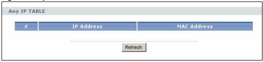
2.5.2 Summary: Any IP Table
This screen displays the IP address of each computer that is using the NBG334W via the any IP feature. Any IP allows computers to access the Internet through the NBG334W without changing their network settings when NAT is enabled. To access this screen, open the Status screen (see Section 2.5 on page 37), and click (Details...) next to Any IP Table.
Figure 6 Any IP Table
2.5.3 Summary: Bandwidth Management Monitor
Select the BW MGMT Monitor (Details...) hyperlink in Status screen. View the bandwidth usage of the WAN configured bandwidth rules. This is also shown as bandwidth usage over the bandwidth budget for each rule. The gray section of the bar represents the percentage of unused bandwidth and the blue color represents the percentage of bandwidth in use.
Figure 7 Summary: BW MGMT Monitor
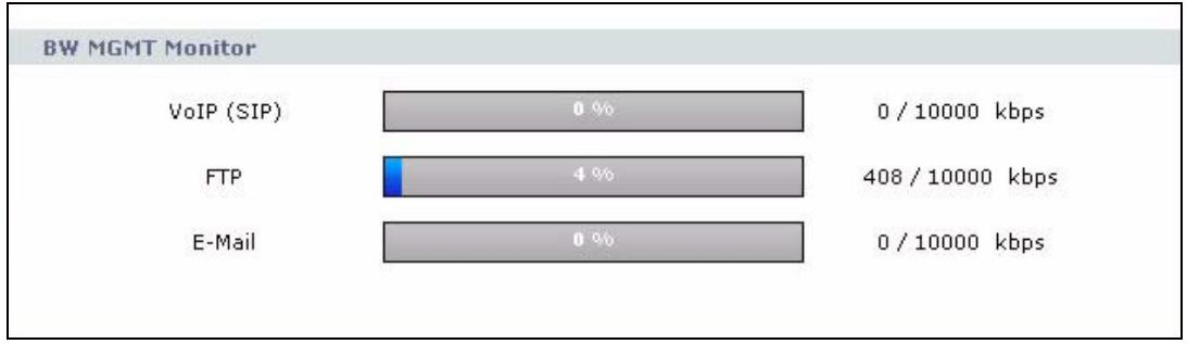
bar
BW MGMT Monitor | Category | Value (%) | Bandwidth (kbps) | | :--- | :--- | :--- | | VoIP (SIP) | 0 | 0 / 10000 | | FTP | 4 | 408 / 10000 | | E-Mail | 0 | 0 / 10000 |2.5.4 Summary: DHCP Table
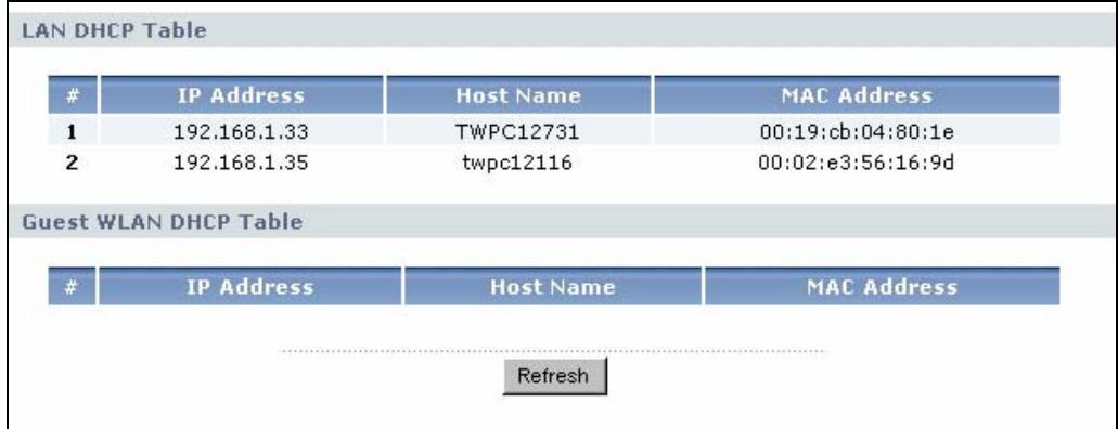
DHCP (Dynamic Host Configuration Protocol, RFC 2131 and RFC 2132) allows individual clients to obtain TCP/IP configuration at start-up from a server. You can configure the NBG334W's LAN and/or Guest WLAN as DHCP server(s) or disable them. When configured as a server, the NBG334W provides the TCP/IP configuration for the clients. If DHCP service is disabled, you must have another DHCP server on that network, or else the computer must be manually configured.
Click the DHCP Table (Details...) hyperlink in the Status screen. Read-only information here relates to your DHCP status. The DHCP table shows current DHCP client information (including IP Address, Host Name and MAC Address) of all network clients using the NBG334W's DHCP server.
Figure 8 Summary: DHCP Table
The following table describes the labels in this screen.
Table 6 Summary: DHCP Table
| LABEL | DESCRIPTION |
| # | This is the index number of the host computer. |
| IP Address | This field displays the IP address relative to the # field listed above. |
| Host Name | This field displays the computer host name. |
| MAC Address | This field shows the MAC address of the computer with the name in the Host Name field.Every Ethernet device has a unique MAC (Media Access Control) address which uniquely identifies a device. The MAC address is assigned at the factory and consists of six pairs of hexadecimal characters, for example, 00:A0:C5:00:00:02. |
| Refresh | Click Refresh to renew the screen. |
2.5.5 Summary: Packet Statistics
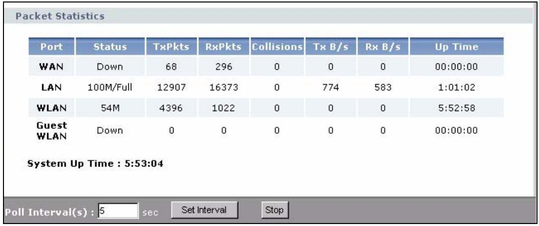
Click the Packet Statistics (Details...) hyperlink in the Status screen. Read-only information here includes port status, packet specific statistics and the "system up time". The Poll Interval(s) field is configurable and is used for refreshing the screen.
Figure 9 Summary: Packet Statistics
The following table describes the labels in this screen.
Table 7 Summary: Packet Statistics
| LABEL | DESCRIPTION |
| Port | This is the NBG334W's port type. |
| Status | For the LAN ports, this displays the port speed and duplex setting or Down when the line is disconnected.For the WAN port, it displays the port speed and duplex setting if you're using Ethernet encapsulation and Idle (line (ppp) idle), Dial (starting to trigger a call) and Drop (dropping a call) if you're using PPPoE or PPTP encapsulation. This field displays Down when the line is disconnected.For the WLAN, it displays the maximum transmission rate when the WLAN is enabled and Down when the WLAN is disabled. |
| TxPkts | This is the number of transmitted packets on this port. |
| RxPkts | This is the number of received packets on this port. |
| Collisions | This is the number of collisions on this port. |
| Tx B/s | This displays the transmission speed in bytes per second on this port. |
| Rx B/s | This displays the reception speed in bytes per second on this port. |
| Up Time | This is the total amount of time the line has been up. |
| System Up Time | This is the total time the NBG334W has been on. |
| Poll Interval(s) | Enter the time interval for refreshing statistics in this field. |
| Set Interval | Click this button to apply the new poll interval you entered in the Poll Interval(s) field. |
| Stop | Click Stop to stop refreshing statistics. |
2.5.6 Summary: Wireless Station Status
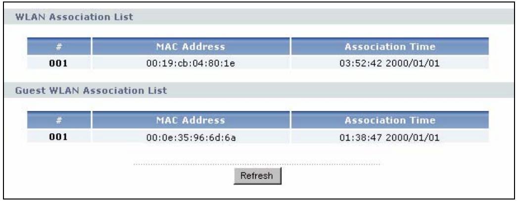
Click the WLAN Station Status (Details...) hyperlink in the Status screen. View the wireless stations that are currently associated to the NBG334W in the WLAN Association List and Guest WLAN Association List sections. Association means that a wireless client (for example, your network or computer with a wireless network card) has connected successfully to the AP (or wireless router) using the same SSID, channel and security settings.
Figure 10 Summary: Wireless Association List
The following table describes the labels in this screen.
Table 8 Summary: Wireless Association List
| LABEL | DESCRIPTION |
| # | This is the index number of an associated wireless station. |
| MAC Address | This field displays the MAC address of an associated wireless station. |
| Association Time | This field displays the time a wireless station first associated with the NBG334W's LAN or Guest WLAN network. |
| Refresh | Click Refresh to reload the list. |
Connection Wizard
This chapter provides information on the wizard setup screens in the web configurator.
3.1 Wizard Setup
The web configurator's wizard setup helps you configure your device to access the Internet. Refer to your ISP (Internet Service Provider) checklist in the Quick Start Guide to know what to enter in each field. Leave a field blank if you don't have that information.
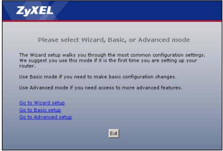
1 After you access the NBG334W web configurator, click the Go to Wizard setup hyperlink.
You can click the Go to Basic setup or Go to Advanced setup hyperlink to skip this wizard setup and configure basic or advanced features accordingly.
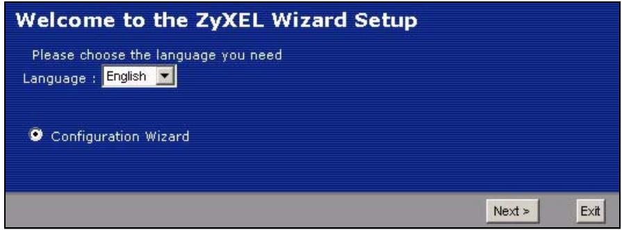
Figure 11 Select Wizard or Advanced Mode
2 Choose your language from the drop-down list box.
3 Click the Next button to proceed to the next screen.
Figure 12 Select a Language
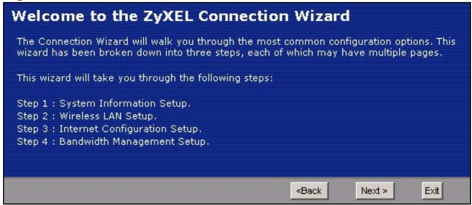
4 Read the on-screen information and click Next.
Figure 13 Welcome to the Connection Wizard
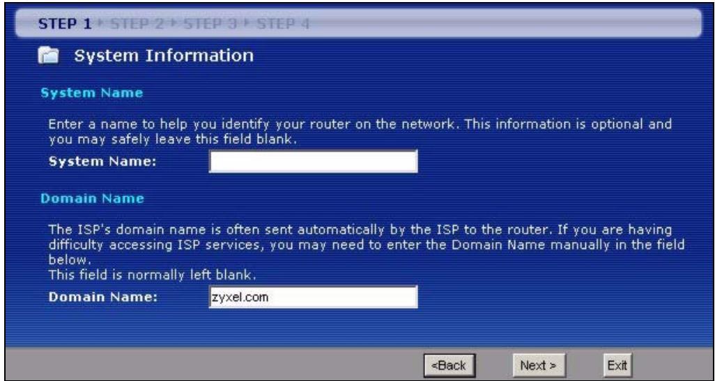
3.2 Connection Wizard: STEP 1: System Information
System Information contains administrative and system-related information.
3.2.1 System Name
System Name is for identification purposes. However, because some ISPs check this name you should enter your computer's "Computer Name".
- In Windows 95/98 click Start, Settings, Control Panel, Network. Click the Identification tab, note the entry for the Computer Name field and enter it as the System Name.
- In Windows 2000, click Start, Settings and Control Panel and then double-click System. Click the Network Identification tab and then the Properties button. Note the entry for the Computer name field and enter it as the System Name.
- In Windows XP, click Start, My Computer, View system information and then click the Computer Name tab. Note the entry in the Full computer name field and enter it as the NBG334W System Name.
3.2.2 Domain Name
The Domain Name entry is what is propagated to the DHCP clients on the LAN. If you leave this blank, the domain name obtained by DHCP from the ISP is used. While you must enter the host name (System Name) on each individual computer, the domain name can be assigned from the NBG334W via DHCP.
Click Next to configure the NBG334W for Internet access.
Figure 14 Wizard Step 1: System Information
The following table describes the labels in this screen.
Table 9 Wizard Step 1: System Information
| LABEL | DESCRIPTION |
| System Name | System Name is a unique name to identify the NBG334W in an Ethernet network. Enter a descriptive name. This name can be up to 30 alphanumeric characters long. Spaces are not allowed, but dashes "-" and underscores "_" are accepted. |
| Domain Name | Type the domain name (if you know it) here. If you leave this field blank, the ISP may assign a domain name via DHCP. The domain name entered by you is given priority over the ISP assigned domain name. |
| Back | Click Back to display the previous screen. |
| Next | Click Next to proceed to the next screen. |
| Exit | Click Exit to close the wizard screen without saving. |
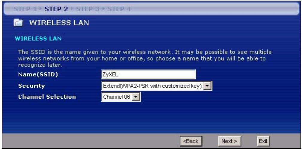
3.3 Connection Wizard: STEP 2: Wireless LAN
Set up your wireless LAN using the following screen.
Figure 15 Wizard Step 2: Wireless LAN
The following table describes the labels in this screen.
Table 10 Wizard Step 2: Wireless LAN
| LABEL | DESCRIPTION |
| Name (SSID) | Enter a descriptive name (up to 32 printable 7-bit ASCII characters) for the wireless LAN.If you change this field on the NBG334W, make sure all wireless stations use the same SSID in order to access the network. |
| Security | Select a Security level from the drop-down list box.Choose Auto to have the NBG334W generate a pre-shared key automatically. A screen pops up displaying the generated pre-shared key after you click Next. Write down the key for use later when connecting other wireless devices to your network.Click OK to continue.Choose None to have no wireless LAN security configured. If you do not enable any wireless security on your NBG334W, your network is accessible to any wireless networking device that is within range. If you choose this option, skip directly to Section 3.4 on page 52.Choose Basic (WEP) security if you want to configure WEP Encryption parameters. If you choose this option, go directly to Section 3.3.1 on page 51.Choose Extend (WPA-PSK or WPA2-PSK) security to configure a Pre-Shared Key.Choose this option only if your wireless clients support WPA-PSK or WPA2-PSK respectively. If you choose this option, skip directly to Section 3.3.2 on page 52. |
| Channel Selection | The range of radio frequencies used by IEEE 802.11b/g wireless devices is called a channel.Select a channel that is not used by any nearby devices. |
| Back | Click Back to display the previous screen. |
| Next | Click Next to proceed to the next screen. |
| Exit | Click Exit to close the wizard screen without saving. |

The wireless stations and NBG334W must use the same SSID, channel ID and WEP encryption key (if WEP is enabled), WPA-PSK (if WPA-PSK is enabled) or WPA2-PSK (if WPA2-PSK is enabled) for wireless communication.
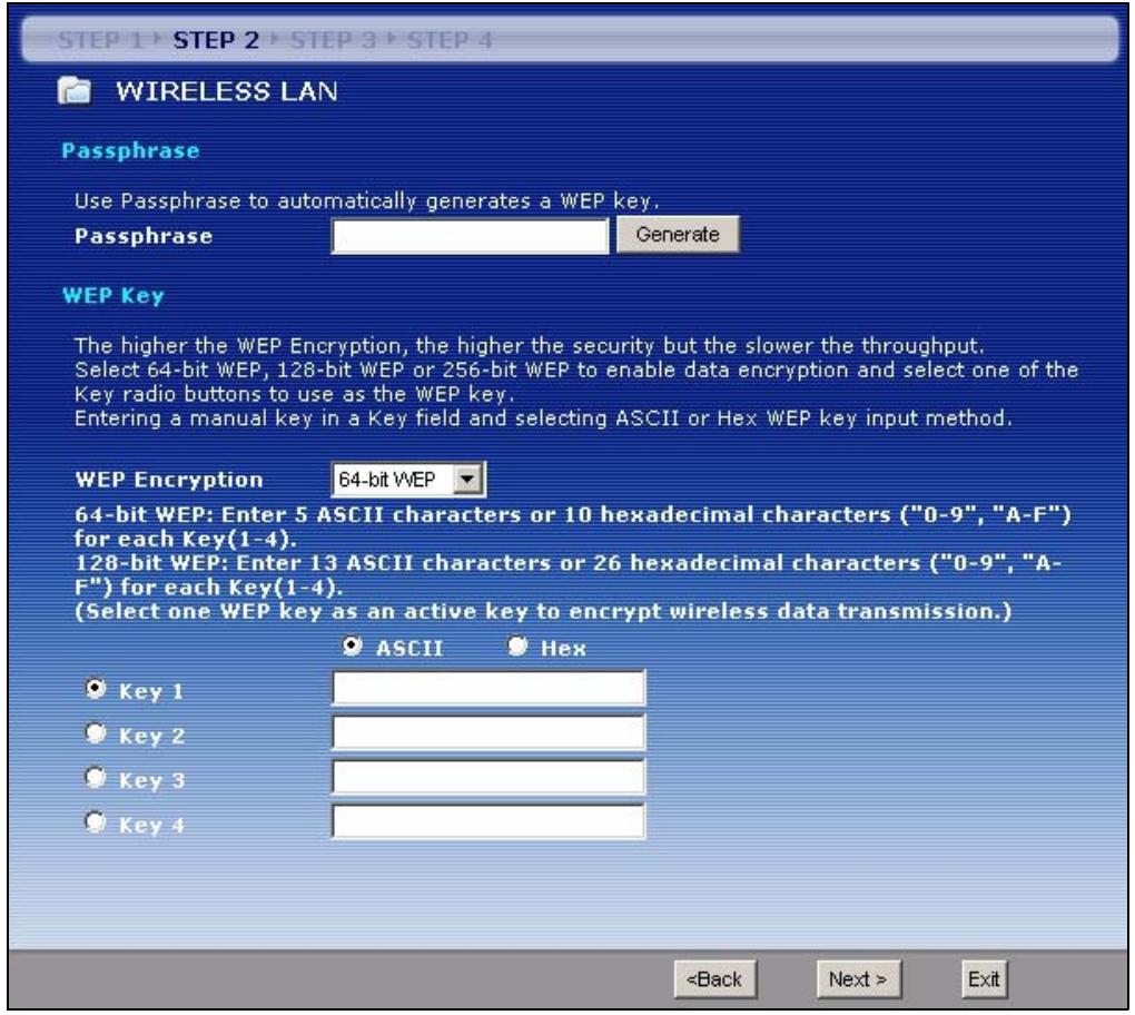
3.3.1 Basic (WEP) Security
Choose Basic (WEP) to setup WEP Encryption parameters.
Figure 16 Wizard Step 2: Basic (WEP) Security
The following table describes the labels in this screen.
Table 11 Wizard Step 2: Basic (WEP) Security
| LABEL | DESCRIPTION |
| Passphrase | Type a Passphrase (up to 32 printable characters) and click Generate. The NBG334W automatically generates a WEP key. |
| WEP Encryption | Select 64-bit WEP or 128-bit WEP to allow data encryption. |
| ASCII | Select this option in order to enter ASCII characters as the WEP keys. |
| HEX | Select this option to enter hexadecimal characters as the WEP keys.The preceding “0x” is entered automatically. |
| Key 1 to Key 4 | The WEP keys are used to encrypt data. Both the NBG334W and the wireless stations must use the same WEP key for data transmission.If you chose 64-bit WEP, then enter any 5 ASCII characters or 10 hexadecimal characters ("0-9", "A-F").If you chose 128-bit WEP, then enter 13 ASCII characters or 26 hexadecimal characters ("0-9", "A-F").You must configure at least one key, only one key can be activated at any one time. The default key is key 1. |
| Back | Click Back to display the previous screen. |
Table 11 Wizard Step 2: Basic (WEP) Security
| LABEL | DESCRIPTION |
| Next | Click Next to proceed to the next screen. |
| Exit | Click Exit to close the wizard screen without saving. |
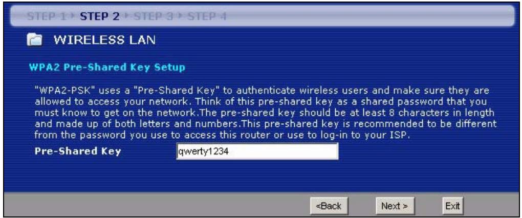
3.3.2 Extend (WPA-PSK or WPA2-PSK) Security
Choose Extend (WPA-PSK) or Extend (WPA2-PSK) security in the Wireless LAN setup screen to set up a Pre-Shared Key.
Figure 17 Wizard Step 2: Extend (WPA-PSK or WPA2-PSK) Security
The following table describes the labels in this screen.
Table 12 Wizard Step 2: Extend (WPA-PSK or WPA2-PSK) Security
| LABEL | DESCRIPTION |
| Pre-Shared Key | Type from 8 to 63 case-sensitive ASCII characters. You can set up the most secure wireless connection by configuring WPA in the wireless LAN screens. You need to configure an authentication server to do this. |
| Back | Click Back to display the previous screen. |
| Next | Click Next to proceed to the next screen. |
| Exit | Click Exit to close the wizard screen without saving. |
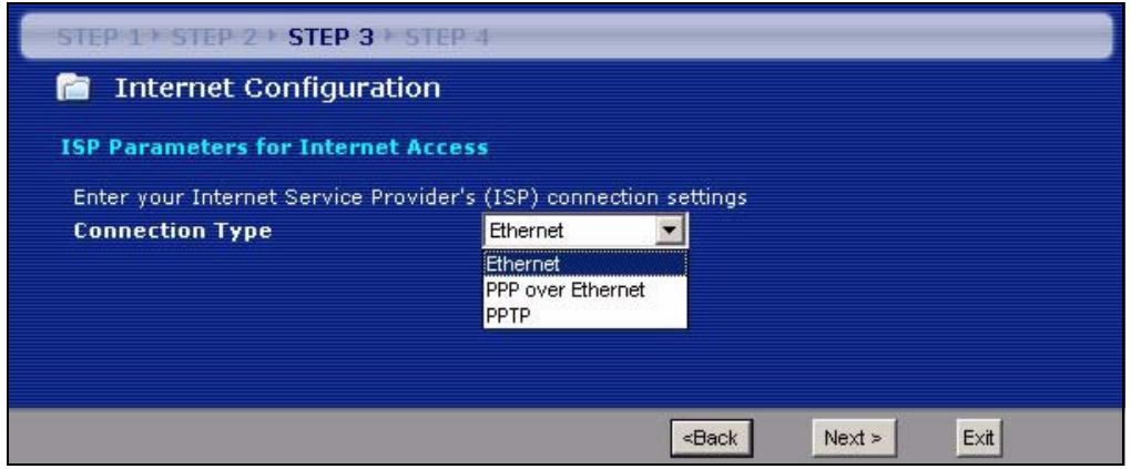
3.4 Connection Wizard: STEP 3: Internet Configuration
The NBG334W offers three Internet connection types. They are Ethernet, PPP over Ethernet or PPTP. The wizard attempts to detect which WAN connection type you are using. If the wizard does not detect a connection type, you must select one from the drop-down list box. Check with your ISP to make sure you use the correct type.
This wizard screen varies according to the connection type that you select.
Figure 18 Wizard Step 3: ISP Parameters.
The following table describes the labels in this screen,
Table 13 Wizard Step 3: ISP Parameters
| CONNECTION TYPE | DESCRIPTION |
| Ethernet | Select the Ethernet option when the WAN port is used as a regular Ethernet. |
| PPPoE | Select the PPP over Ethernet option for a dial-up connection. If your ISP gave you a an IP address and/or subnet mask, then select PPTP. |
| PPTP | Select the PPTP option for a dial-up connection. |
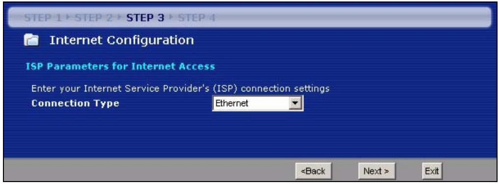
3.4.1 Ethernet Connection
Choose Ethernet when the WAN port is used as a regular Ethernet.
Figure 19 Wizard Step 3: Ethernet Connection
3.4.2 PPPoE Connection
Point-to-Point Protocol over Ethernet (PPPoE) functions as a dial-up connection. PPPoE is an IETF (Internet Engineering Task Force) standard specifying how a host personal computer interacts with a broadband modem (for example DSL, cable, wireless, etc.) to achieve access to high-speed data networks.
For the service provider, PPPoE offers an access and authentication method that works with existing access control systems (for instance, RADIUS).
One of the benefits of PPPoE is the ability to let end users access one of multiple network services, a function known as dynamic service selection. This enables the service provider to easily create and offer new IP services for specific users.
Operationally, PPPoE saves significant effort for both the subscriber and the ISP/carrier, as it requires no specific configuration of the broadband modem at the subscriber's site.
By implementing PPPoE directly on the NBG334W (rather than individual computers), the computers on the LAN do not need PPPoE software installed, since the NBG334W does that part of the task. Furthermore, with NAT, all of the LAN's computers will have Internet access.
Refer to the appendix for more information on PPPoE.
Figure 20 Wizard Step 3: PPPoE Connection
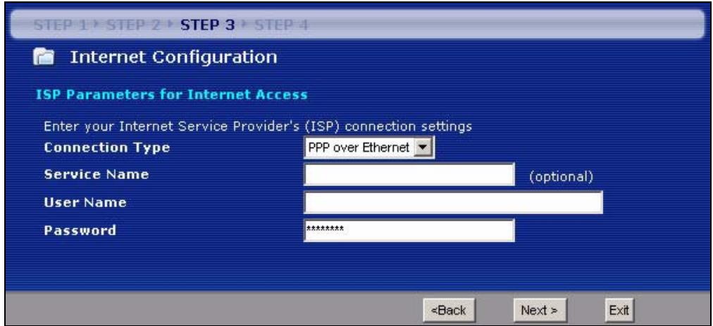
The following table describes the labels in this screen.
Table 14 Wizard Step 3: PPPoE Connection
| LABEL | DESCRIPTION |
| ISP Parameter for Internet Access | |
| Connection Type | Select the PPP over Ethernet option for a dial-up connection. |
| Service Name | Type the name of your service provider. |
| User Name | Type the user name given to you by your ISP. |
| Password | Type the password associated with the user name above. |
| Back | Click Back to return to the previous screen. |
| Next | Click Next to continue. |
| Exit | Click Exit to close the wizard screen without saving. |
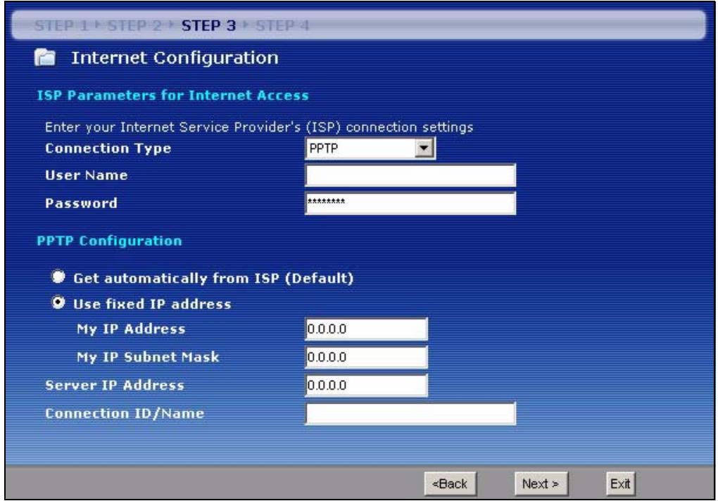
3.4.3 PPTP Connection
Point-to-Point Tunneling Protocol (PPTP) is a network protocol that enables transfers of data from a remote client to a private server, creating a Virtual Private Network (VPN) using TCP/IP-based networks.
PPTP supports on-demand, multi-protocol, and virtual private networking over public networks, such as the Internet.
Refer to the appendix for more information on PPTP.

The NBG334W supports one PPTP server connection at any given time.
Figure 21 Wizard Step 3: PPTP Connection
The following table describes the fields in this screen
Table 15 Wizard Step 3: PPTP Connection
| LABEL | DESCRIPTION |
| ISP Parameters for Internet Access | |
| Connection Type | Select PPTP from the drop-down list box. To configure a PPTP client, you must configure the User Name and Password fields for a PPP connection and the PPTP parameters for a PPTP connection. |
| User Name | Type the user name given to you by your ISP. |
| Password | Type the password associated with the User Name above. |
| PPTP Configuration | |
| Get automatically from ISP | Select this radio button if your ISP did not assign you a fixed IP address. |
| Use fixed IP address | Select this radio button, provided by your ISP to give the NBG334W a fixed, unique IP address. |
| My IP Address | Type the (static) IP address assigned to you by your ISP. |
| My IP Subnet Mask | Type the subnet mask assigned to you by your ISP (if given). |
| Server IP Address | Type the IP address of the PPTP server. |
| Connection ID/Name | Enter the connection ID or connection name in this field. It must follow the "c:id" and "n:name" format. For example, C:12 or N:My ISP.This field is optional and depends on the requirements of your ISP. |
| Back | Click Back to return to the previous screen. |
Table 15 Wizard Step 3: PPTP Connection
| LABEL | DESCRIPTION |
| Next | Click Next to continue. |
| Exit | Click Exit to close the wizard screen without saving. |
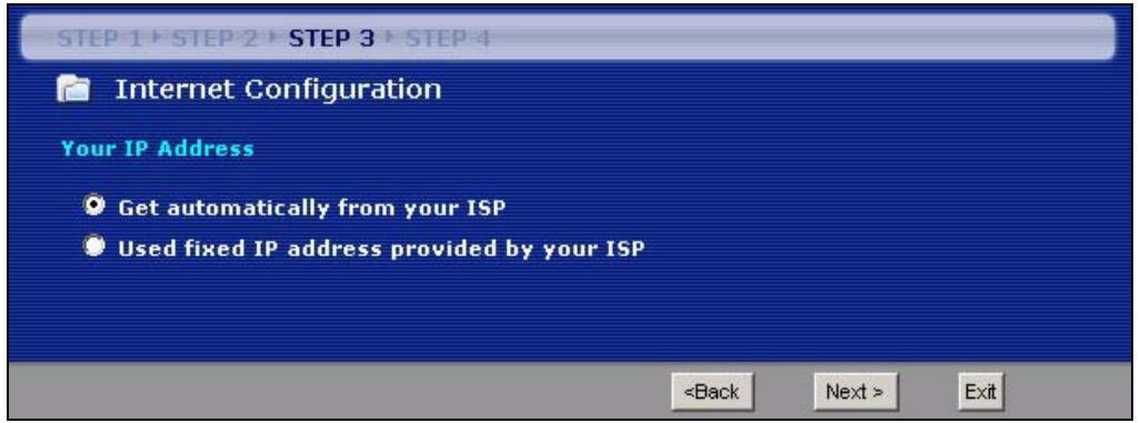
3.4.4 Your IP Address
The following wizard screen allows you to assign a fixed IP address or give the NBG334W an automatically assigned IP address depending on your ISP.
Figure 22 Wizard Step 3: Your IP Address
The following table describes the labels in this screen
Table 16 Wizard Step 3: Your IP Address
| LABEL | DESCRIPTION |
| Get automatically from your ISP | Select this option If your ISP did not assign you a fixed IP address. This is the default selection. If you choose this option, skip directly to section 3.4.9. |
| Use fixed IP address provided by your ISP | Select this option if you were given IP address and/or DNS server settings by the ISP. The fixed IP address should be in the same subnet as your broadband modem or router. |
| Back | Click Back to return to the previous screen. |
| Next | Click Next to continue. |
| Exit | Click Exit to close the wizard screen without saving. |
3.4.5 WAN IP Address Assignment
Every computer on the Internet must have a unique IP address. If your networks are isolated from the Internet, for instance, only between your two branch offices, you can assign any IP addresses to the hosts without problems. However, the Internet Assigned Numbers Authority (IANA) has reserved the following three blocks of IP addresses specifically for private networks.
Table 17 Private IP Address Ranges
| 10.0.0.0 | - | 10.255.255.255 |
| 172.16.0.0 | - | 172.31.255.255 |
| 192.168.0.0 | - | 192.168.255.255 |
You can obtain your IP address from the IANA, from an ISP or have it assigned by a private network. If you belong to a small organization and your Internet access is through an ISP, the ISP can provide you with the Internet addresses for your local networks. On the other hand, if you are part of a much larger organization, you should consult your network administrator for the appropriate IP addresses.

Regardless of your particular situation, do not create an arbitrary IP address; always follow the guidelines above. For more information on address assignment, please refer to RFC 1597, Address Allocation for Private Internets and RFC 1466, Guidelines for Management of IP Address Space.
3.4.6 IP Address and Subnet Mask
Similar to the way houses on a street share a common street name, so too do computers on a LAN share one common network number.
Where you obtain your network number depends on your particular situation. If the ISP or your network administrator assigns you a block of registered IP addresses, follow their instructions in selecting the IP addresses and the subnet mask.
If the ISP did not explicitly give you an IP network number, then most likely you have a single user account and the ISP will assign you a dynamic IP address when the connection is established. The Internet Assigned Number Authority (IANA) reserved this block of addresses specifically for private use; please do not use any other number unless you are told otherwise. Let's say you select 192.168.1.0 as the network number; which covers 254 individual addresses, from 192.168.1.1 to 192.168.1.254 (zero and 255 are reserved). In other words, the first three numbers specify the network number while the last number identifies an individual computer on that network.
Once you have decided on the network number, pick an IP address that is easy to remember, for instance, 192.168.1.1, for your NBG334W, but make sure that no other device on your network is using that IP address.
The subnet mask specifies the network number portion of an IP address. Your NBG334W will compute the subnet mask automatically based on the IP address that you entered. You don't need to change the subnet mask computed by the NBG334W unless you are instructed to do otherwise.
3.4.7 DNS Server Address Assignment
Use DNS (Domain Name System) to map a domain name to its corresponding IP address and vice versa, for instance, the IP address of www.zyxel.com is 204.217.0.2. The DNS server is extremely important because without it, you must know the IP address of a computer before you can access it.
The NBG334W can get the DNS server addresses in the following ways.
1 The ISP tells you the DNS server addresses, usually in the form of an information sheet, when you sign up. If your ISP gives you DNS server addresses, enter them in the DNS Server fields in the Wizard and/or WAN > Internet Connection screen.
2 If the ISP did not give you DNS server information, leave the DNS Server fields set to 0.0.0.0 in the Wizard screen and/or set to From ISP in the WAN > Internet Connection screen for the ISP to dynamically assign the DNS server IP addresses.
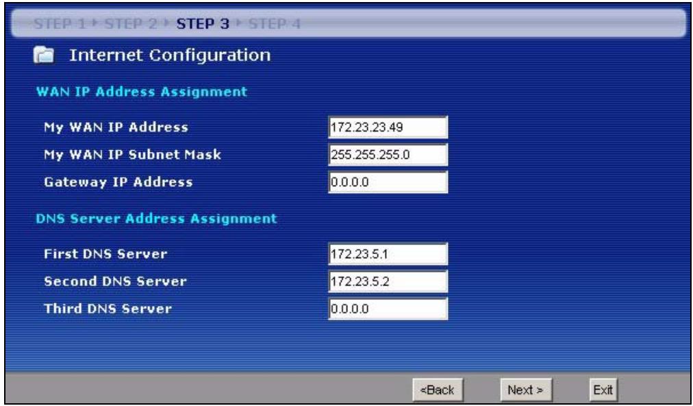
3.4.8 WAN IP and DNS Server Address Assignment
The following wizard screen allows you to assign a fixed WAN IP address and DNS server addresses.
Figure 23 Wizard Step 3: WAN IP and DNS Server Addresses
The following table describes the labels in this screen
Table 18 Wizard Step 3: WAN IP and DNS Server Addresses
| LABEL | DESCRIPTION |
| WAN IP Address Assignment | |
| My WAN IP Address | Enter your WAN IP address in this field. The WAN IP address should be in the same subnet as your DSL/Cable modem or router. |
| My WAN IP Subnet Mask | Enter the IP subnet mask in this field. |
| Gateway IP Address | Enter the gateway IP address in this field. |
| System DNS Server Address Assignment (if applicable)DNS (Domain Name System) is for mapping a domain name to its corresponding IP address and vice versa. The DNS server is extremely important because without it, you must know the IP address of a computer before you can access it. The NBG334W uses a system DNS server (in the order you specify here) to resolve domain names for DDNS and the time server. | |
| First DNS ServerSecond DNS ServerThird DNS Server | Enter the DNS server's IP address in the fields provided.If you do not configure a system DNS server, you must use IP addresses when configuring DDNS and the time server. |
| Back | Click Back to return to the previous screen. |
| Next | Click Next to continue. |
| Exit | Click Exit to close the wizard screen without saving. |
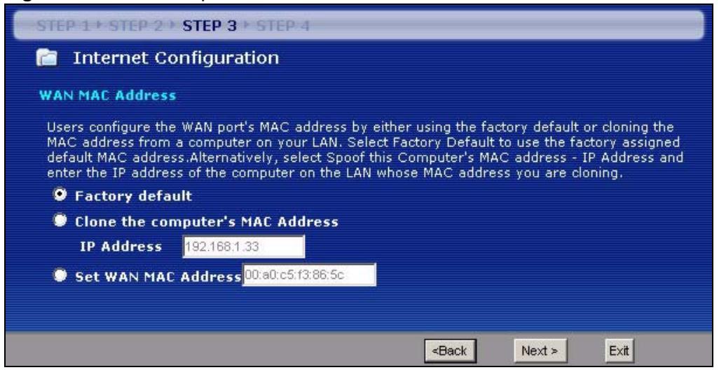
3.4.9 WAN MAC Address
Every Ethernet device has a unique MAC (Media Access Control) address. The MAC address is assigned at the factory and consists of six pairs of hexadecimal characters, for example, 00:A0:C5:00:00:02.
Table 19 Example of Network Properties for LAN Servers with Fixed IP Addresses
| Choose an IP address | 192.168.1.2-192.168.1.32; 192.168.1.65-192.168.1.254. |
| Subnet mask | 255.255.255.0 |
| Gateway (or default route) | 192.168.1.1(NBG334W LAN IP) |
This screen allows users to configure the WAN port's MAC address by either using the NBG334W's MAC address, copying the MAC address from a computer on your LAN or manually entering a MAC address. Once it is successfully configured, the address will be copied to the "rom" file (ZyNOS configuration file). It will not change unless you change the setting or upload a different "rom" file. It is advisable to clone the MAC address from a computer on your LAN even if your ISP does not presently require MAC address authentication.
Figure 24 Wizard Step 3: WAN MAC Address
The following table describes the fields in this screen.
Table 20 Wizard Step 3: WAN MAC Address
| LABEL | DESCRIPTION |
| Factory Default | Select Factory Default to use the factory assigned default MAC address. |
| Clone the computer's MAC address | Select this option and enter the IP address of the computer on the LAN whose MAC you are cloning. It is advisable to clone the MAC address from a computer on your LAN even if your ISP does not presently require MAC address authentication. |
| Set WAN MAC Address | Select this option and enter the MAC address you want to use. |
| Back | Click Back to return to the previous screen. |
| Next | Click Next to continue. |
| Exit | Click Exit to close the wizard screen without saving. |
3.5 Connection Wizard: STEP 4: Bandwidth management
Bandwidth management allows you to control the amount of bandwidth going out through the NBG334W's WAN, LAN or WLAN port and prioritize the distribution of the bandwidth according to the traffic type. This helps keep one service from using all of the available bandwidth and shutting out other users.
Figure 25 Wizard Step 4: Bandwidth Management

The following fields describe the label in this screen.
Table 21 Wizard Step 4: Bandwidth Management
| LABEL | DESCRIPTION |
| Enable BM for all traffic automatically | Select the check box to have the NBG334W apply bandwidth management to traffic going out through the NBG334W's WAN, LAN, HomePlug AV or WLAN port. Bandwidth is allocated according to the traffic type automatically. Real-time packets, such as VoIP traffic always get higher priority. |
| Back | Click Back to return to the previous screen. |
| Next | Click Next to continue. |
| Exit | Click Exit to close the wizard screen without saving. |
3.6 Connection Wizard Complete
Click Apply to save your configuration.
Figure 26 Connection Wizard Save
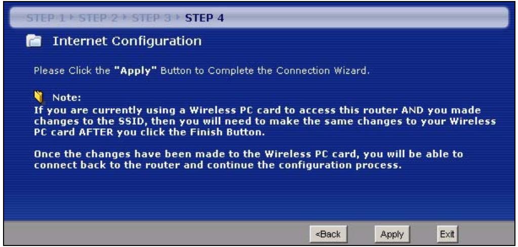
4.1 AP Mode Overview
Use your NBG334W as an AP if you already have a router or gateway on your network. In this mode your device bridges a wired network (LAN) and wireless LAN (WLAN) in the same subnet. See the figure below for an example. Figure 28 Wireless Internet Access in AP Mode flowchart
graph TD
    A["LAN"] --> B["Router"]
    B --> C["Internet"]
    D["WLAN"] --> B
    E["Computer"] --> B
    F["Computer"] --> B
    G["Computer"] --> B
    H["Computer"] --> B
4.2 Setting your NBG334W to AP Mode
1 Log into the web configurator if you haven't already. See the Quick start Guide for instructions on how to do this. 2 To set your NBG334W to AP Mode, go to Maintenance > Sys OP Mode > General and select Access Point. Figure 29 Maintenance > Sys OP Mode > General  3 A pop-up appears providing information on this mode. Click OK in the pop-up message window. (See Section 23.2 on page 216 for more information on the pop-up.) Click Apply. Your NBG334W is now in AP Mode.  You do not have to log in again or restart your device when you change modes.4.3 The Status Screen in AP Mode
Click on Status. The screen below shows the status screen in AP Mode. Figure 30 Status: AP Mode  The following table describes the labels shown in the Status screen. Table 22 Web Configurator Status Screen| LABEL | DESCRIPTION |
| Device Information | |
| System Name | This is the System Name you enter in the Maintenance > System > General screen. It is for identification purposes. |
| Firmware Version | This is the firmware version and the date created. |
| LAN Information | |
| - MAC Address | This shows the LAN Ethernet adapter MAC Address of your device. |
| - IP Address | This shows the LAN port's IP address. |
| - IP Subnet Mask | This shows the LAN port's subnet mask. |
| - DHCP | This shows the LAN port's DHCP role - Client or None. |
| WLAN Information | |
| - MAC Address | This shows the wireless adapter MAC Address of your device. |
| - Name (SSID) | This shows a descriptive name used to identify the NBG334W in the wireless LAN. |
| - Channel | This shows the channel number which you select manually. |
| - Operating Channel | This shows the channel number which the NBG334W is currently using over the wireless LAN. |
| - Security Mode | This shows the level of wireless security the NBG334W is using. |
| - 802.11 Mode | This shows the IEEE 802.11 standard that the NBG334W supports. Wireless clients must support the same standard in order to be able to connect to the NBG334W |
| - WPS | This shows the WPS (WiFi Protected Setup) Status. Click the status to display Network > Wireless LAN > WPS screen. |
| System Status | |
| System Uptime | This is the total time the NBG334W has been on. |
| Current Date/Time | This field displays your NBG334W's present date and time. |
| System Resource | |
| - CPU Usage | This displays what percentage of the NBG334W's processing ability is currently used. When this percentage is close to 100%, the NBG334W is running at full load, and the throughput is not going to improve anymore. If you want some applications to have more throughput, you should turn off other applications (for example, using bandwidth management. |
| - Memory Usage | This shows what percentage of the heap memory the NBG334W is using. Heap memory refers to the memory that is not used by ZyNOS (ZyXEL Network Operating System) and is thus available for running processes like NAT and the firewall. |
| System Setting | |
| - Configuration Mode | This shows whether the advanced screens of each feature are turned on (Advanced) or not (Basic). |
| - System Operation Mode | This shows whether the system is configured to connect to the Internet in Router Mode or Access Point Mode. |
| Interface Status | |
| Interface | This displays the NBG334W port types. The port types are: LAN and WLAN. |
| Status | For the LAN port, this field displays Down (line is down) or Up (line is up or connected). For the WLAN, it displays Up when the WLAN is enabled or Down when the WLAN is disabled. |
| Rate | For the LAN ports, this displays the port speed and duplex setting or N/A when the line is disconnected.For the WLAN, it displays the maximum transmission rate when the WLAN is enabled and N/A when the WLAN is disabled. |
| Summary | |
| Packet Statistics | Use this screen to view port status and packet specific statistics. |
| WLAN Station Status | Use this screen to view the wireless stations that are currently associated to the NBG334W. |
4.3.1 Navigation Panel
Use the menu in the navigation panel to configure NBG334W features in AP Mode. The following screen and table show the features you can configure in AP Mode. Figure 31 Menu: AP Mode  The following table describes the sub-menus. Table 23 Screens Summary| LINK | TAB | FUNCTION |
| Status | This screen shows the NBG334W's general device, system and interface status information. Use this screen to access the wizard, and summary statistics tables. | |
| Network |
| LINK | TAB | FUNCTION |
| Wireless LAN | General | Use this screen to configure wireless LAN. |
| MAC Filter | Use the MAC filter screen to configure the NBG334W to block access to devices or block the devices from accessing the NBG334W. | |
| Advanced | This screen allows you to configure advanced wireless settings. | |
| QoS | Use this screen to configure Wi-Fi Multimedia Quality of Service (WMM QoS). WMM QoS allows you to prioritize wireless traffic according to the delivery requirements of individual services. | |
| WPS | Use this screen to configure WPS. | |
| WPS Station | Use this screen to add a wireless station using WPS. | |
| LAN | IP | Use this screen to configure LAN IP address and subnet mask or to get the LAN IP address from a DHCP server. |
| Maintenance | ||
| System | General | Use this screen to view and change administrative settings such as system and domain names, password and inactivity timer. |
| Time Setting | Use this screen to change your NBG334W's time and date. | |
| Logs | View Log | Use this screen to view the logs for the categories that you selected. |
| Log Settings | Use this screen to change your NBG334W's log settings. | |
| Tools | Firmware | Use this screen to upload firmware to your NBG334W. |
| Configuration | Use this screen to backup and restore the configuration or reset the factory defaults to your NBG334W. | |
| Restart | This screen allows you to reboot the NBG334W without turning the power off. | |
| Config Mode | General | This screen allows you to display or hide the advanced screens or features. |
| Language | This screen allows you to select the language you prefer. |
4.4 Configuring Your Settings
4.4.1 LAN Settings
Use this section to configure your LAN settings while in AP Mode. Click Network > LAN to see the screen below.  If you change the IP address of the NBG334W in the screen below, you will need to log into the NBG334W again using the new IP address. Figure 32 Network > LAN > IP  The table below describes the labels in the screen. Table 24 Network > LAN > IP| LABEL | DESCRIPTION |
| Get form DHCP Server | Select this option to allow the NBG334W to obtain an IP address from a DHCP server on the network. You must connect the WAN port to a device with a DHCP server enabled (such as a router or gateway). Without a DHCP server the NBG334W will have no IP address. You need to find out the IP address the DHCP server assigns to the NBG334W and use that address to log in to the NBG334W again. |
| User Defined LAN IP | Select this option to set the NBG334W's IP address. This setting is selected by default. Check the IP address is on the same domain as other devices on your network. |
| IP Address | Type the IP address in dotted decimal notation. The default setting is 192.168.1.1. If you change the IP address you will have to log in again with the new IP address. |
| IP Subnet Mask | The subnet mask specifies the network number portion of an IP address. Your NBG334W will automatically calculate the subnet mask based on the IP address that you assign. Unless you are implementing subnetting, use the subnet mask computed by the NBG334W. |
| Gateway IP Address | Type the IP address of the gateway. The gateway is an immediate neighbor of your NBG334W that will forward the packet to the destination. In AP Mode, the gateway must be a router on the same segment as your NBG334W. |
| Apply | Click Apply to save your changes to the NBG334W. |
| Reset | Click Reset to reload the previous configuration for this screen. |
4.4.2 WLAN and Maintenance Settings
The configuration of wireless and maintenance settings in AP Mode is the same as for Router Mode. • See Chapter 5 on page 69 for information on the configuring your wireless network. - See Maintenance and Troubleshooting (187) for information on the configuring your Maintenance settings.4.5 Logging in to the Web Configurator in AP Mode
1 Connect your computer to the LAN port of the NBG334W. 2 The default IP address if the NBG334W is “192.168.1.1”. In this case, your computer must have an IP address in the range between “192.168.1.2” and “192.168.1.255”. 3 Click Start > Run on your computer in Windows. 4 Type "cmd" in the dialog box. 5 Type “ipconfig” to show your computer’s IP address. If your computer’s IP address is not in the correct range then see Appendix D on page 249 for information on changing your computer’s IP address. 6 After you've set your computer's IP address, open a web browser such as Internet Explorer and type "192.168.1.1" as the web address in your web browser. See Chapter 6 on page 93 for a tutorial on setting up a network with an AP.PART II
Network
Wireless LAN (73) Wireless Tutorial (93) WAN (101) LAN (111) Guest WLAN (117) DHCP (123) Network Address Translation (NAT) (129) Dynamic DNS (139)Wireless LAN
This chapter discusses how to configure the wireless network settings in your NBG334W. See the appendices for more detailed information about wireless networks.5.1 Wireless Network Overview
The following figure provides an example of a wireless network. Figure 33 Example of a Wireless Network flowchart
graph TD
    A["Computer A"] -->|Wireless Signal| AP["AP"]
    B["Computer B"] -->|Wireless Signal| AP
    AP -->|Wireless Signal| A
    style AP fill:#f9f,stroke:#333
    style A fill:#ccf,stroke:#333
    style B fill:#ccf,stroke:#333
Requirements
To add a wireless LAN to your existing network, make sure you have the following: 1 an access point (AP) or a router with the wireless feature 2 at least one wireless network card/adapter which varies according to your computer. - If you have a desktop, use either a wireless USB adapter or a wireless PCI adapter. - If you have a laptop, use either a wireless USB adapter or a wireless CardBus card. - If you have a desktop, use either a wireless USB adapter or a wireless PCI adapter. - If you have a laptop, use either a wireless USB adapter or a wireless CardBus card. 3 a RADIUS server only if you want to use IEEE802.1x, WPA or WPA2 To have two or more computers communicate with each other wirelessly without an AP or wireless router, make sure you have the following: 1 two or more wireless network cards/adapters which vary according to your computers. \- If you have a desktop, use either a wireless USB adapter or a wireless PCI adapter. \- If you have a laptop, use either a wireless USB adapter or a wireless CardBus card.Setup Information
To set up your wireless network using an AP or wireless router, make sure your AP or wireless router and wireless network card(s)/adapter(s) use the same following settings: - SSID: - Channel: auto or \_\_\_\_ • Network type of a wireless network card/adapter: Infrastructure - wireless standard: IEEE 802.11b, g, b/g or a - Security: ( ) None ( ) WEP (64bit, 128bit or 256bit key) (ASCII or Hex): \_\_\_\_ ( ) IEEE 802.1x ( ) WPA-PSK (TKIP or AES): ( ) WPA (TKIP or AES) ( ) WPA2-PSK (TKIP or AES): \_\_\_\_ ( ) WPA2 (TKIP or AES) \- Preamble type (if available): auto, short or long To set up your wireless network without an AP or wireless router, make sure wireless network cards/adapters use the same following settings: • Network type: Ad-Hoc - SSID: - Channel: - wireless standard: IEEE 802.11b, g, b/g or a - Security: ( ) None ( ) WEP (64bit, 128bit or 256bit key) (ASCII or Hex): \_\_\_\_5.2 Wireless Security Overview
The following sections introduce different types of wireless security you can set up in the wireless network.5.2.1 SSID
Normally, the AP acts like a beacon and regularly broadcasts the SSID in the area. You can hide the SSID instead, in which case the AP does not broadcast the SSID. In addition, you should change the default SSID to something that is difficult to guess. This type of security is fairly weak, however, because there are ways for unauthorized devices to get the SSID. In addition, unauthorized devices can still see the information that is sent in the wireless network.5.2.2 MAC Address Filter
Every wireless client has a unique identification number, called a MAC address. ^1 A MAC address is usually written using twelve hexadecimal characters ^2 ; for example, 00A0C5000002 or 00:A0:C5:00:00:02. To get the MAC address for each wireless client, see the appropriate User's Guide or other documentation. You can use the MAC address filter to tell the AP which wireless clients are allowed or not allowed to use the wireless network. If a wireless client is allowed to use the wireless network, it still has to have the correct settings (SSID, channel, and security). If a wireless client is not allowed to use the wireless network, it does not matter if it has the correct settings. This type of security does not protect the information that is sent in the wireless network. Furthermore, there are ways for unauthorized devices to get the MAC address of an authorized wireless client. Then, they can use that MAC address to use the wireless network.5.2.3 User Authentication
You can make every user log in to the wireless network before they can use it. This is called user authentication. However, every wireless client in the wireless network has to support IEEE 802.1x to do this. For wireless networks, there are two typical places to store the user names and passwords for each user. - In the AP: this feature is called a local user database or a local database. - In a RADIUS server: this is a server used in businesses more than in homes. If your AP does not provide a local user database and if you do not have a RADIUS server, you cannot set up user names and passwords for your users. Unauthorized devices can still see the information that is sent in the wireless network, even if they cannot use the wireless network. Furthermore, there are ways for unauthorized wireless users to get a valid user name and password. Then, they can use that user name and password to use the wireless network. Local user databases also have an additional limitation that is explained in the next section.5.2.4 Encryption
Wireless networks can use encryption to protect the information that is sent in the wireless network. Encryption is like a secret code. If you do not know the secret code, you cannot understand the message. The types of encryption you can choose depend on the type of user authentication. (See Section 5.2.3 on page 76 for information about this.) Table 25 Types of Encryption for Each Type of Authentication| NO AUTHENTICATION | RADIUS SERVER | |
| Weakest↑Strongest | No Security | WPA |
| Static WEP | ||
| WPA-PSK | ||
| WPA2-PSK | WPA2 |
5.3 Roaming
A wireless station is a device with an IEEE 802.11a/b/g compliant wireless interface. An access point (AP) acts as a bridge between the wireless and wired networks. An AP creates its own wireless coverage area. A wireless station can associate with a particular access point only if it is within the access point's coverage area. In a network environment with multiple access points, wireless stations are able to switch from one access point to another as they move between the coverage areas. This is known as roaming. As the wireless station moves from place to place, it is responsible for choosing the most appropriate access point depending on the signal strength, network utilization or other factors. The roaming feature on the access points allows the access points to relay information about the wireless stations to each other. When a wireless station moves from a coverage area to another, it scans and uses the channel of a new access point, which then informs the other access points on the LAN about the change. An example is shown in Figure 34 on page 78. With roaming, a wireless LAN mobile user enjoys a continuous connection to the wired network through an access point while moving around the wireless LAN. Enable roaming to exchange the latest bridge information of all wireless stations between APs when a wireless station moves between coverage areas. Wireless stations can still associate with other APs even if you disable roaming. Enabling roaming ensures correct traffic forwarding (bridge tables are updated) and maximum AP efficiency. The AP deletes records of wireless stations that associate with other APs (Non-ZyXEL APs may not be able to perform this). 802.1x authentication information is not exchanged (at the time of writing). Figure 34 Roaming Example flowchart
graph TD
    subgraph Ethernet
        A["Server"] --> B["AP 1"]
        C["Server"] --> D["AP 2"]
        E["X"] --> F["Y"]
        G["Computer"] --> H["Y"]
    end
    subgraph Ethernet
        I["Server"] --> J["Y"]
        K["Server"] --> L["Y"]
        M["Computer"] --> N["Y"]
    end
    B <--> D
    D <--> L
    style Ethernet fill:#f9f,stroke:#333
    note right of Ethernet
        direction LR
        note right of Ethernet
        note right of Ethernet
        note left of Ethernet
        note right of Ethernet
        note left of Ethernet
        note right of Ethernet
5.3.1 Requirements for Roaming
The following requirements must be met in order for wireless stations to roam between the coverage areas. 1 All the access points must be on the same subnet and configured with the same ESSID. 2 If IEEE 802.1x user authentication is enabled and to be done locally on the access point, the new access point must have the user profile for the wireless station. 3 The adjacent access points should use different radio channels when their coverage areas overlap. 4 All access points must use the same port number to relay roaming information. 5 The access points must be connected to the Ethernet and be able to get IP addresses from a DHCP server if using dynamic IP address assignment.5.4 Quality of Service
This section discusses the Quality of Service (QoS) features available on the NBG334W.5.4.1 WMM QoS
WMM (Wi-Fi MultiMedia) QoS (Quality of Service) ensures quality of service in wireless networks. It controls WLAN transmission priority on packets to be transmitted over the wireless network. WMM QoS prioritizes wireless traffic according to delivery requirements. WMM QoS is a part of the IEEE 802.11e QoS enhancement to certified Wi-Fi wireless networks. On APs without WMM QoS, all traffic streams are given the same access priority to the wireless network. If the introduction of another traffic stream creates a data transmission demand that exceeds the current network capacity, then the new traffic stream reduces the throughput of the other traffic streams. The NBG334W uses WMM QoS to prioritize traffic streams according to the IEEE 802.1q tag or DSCP information in each packet's header. The NBG334W automatically determines the priority to use for an individual traffic stream. This prevents reductions in data transmission for applications that are sensitive to latency (delay) and jitter (variations in delay).5.4.1.1 WMM QoS Priorities
The following table describes the WMM QoS priority levels that the NBG334W uses. Table 26 WMM QoS Priorities| PRIORITY LEVEL | DESCRIPTION |
| voice(WMM_VOICE) | Typically used for traffic that is especially sensitive to jitter. Use this priority to reduce latency for improved voice quality. |
| video(WMM_VIDEO) | Typically used for traffic which has some tolerance for jitter but needs to be prioritized over other data traffic. |
| best effort(WMM_BEST_EFFORT) | Typically used for traffic from applications or devices that lack QoS capabilities. Use best effort priority for traffic that is less sensitive to latency, but is affected by long delays, such as Internet surfing. |
| background(WMM_BACKGROUND) | This is typically used for non-critical traffic such as bulk transfers and print jobs that are allowed but that should not affect other applications and users. Use background priority for applications that do not have strict latency and throughput requirements. |
5.5 General Wireless LAN Screen
 If you are configuring the NBG334W from a computer connected to the wireless LAN and you change the NBG334W's SSID, channel or security settings, you will lose your wireless connection when you press Apply to confirm. You must then change the wireless settings of your computer to match the NBG334W's new settings. Click Network > Wireless LAN to open the General screen. Figure 35 Network > Wireless LAN > General  The following table describes the general wireless LAN labels in this screen. Table 27 Network > Wireless LAN > General| LABEL | DESCRIPTION |
| Enable Wireless LAN | Click the check box to activate wireless LAN. |
| Name(SSID) | (Service Set IDentity) The SSID identifies the Service Set with which a wireless station is associated. Wireless stations associating to the access point (AP) must have the same SSID. Enter a descriptive name (up to 32 printable 7-bit ASCII characters) for the wireless LAN. |
| Hide SSID | Select this check box to hide the SSID in the outgoing beacon frame so a station cannot obtain the SSID through scanning using a site survey tool. |
| Channel Selection | Set the operating frequency/channel depending on your particular region.Select a channel from the drop-down list box. The options vary depending on whether you are using A or B/G frequency band and the country you are in.Refer to the Connection Wizard chapter for more information on channels. |
| Operating Channel | This displays the channel the NBG334W is currently using. |
| Security Mode | Select Static-WEP, WPA-PSK, WPA, WPA2-PSK, or WPA2 to add security on this wireless network. The wireless clients which want to associate to this network must have same wireless security settings as this device. After you select to use a security, additional options appears in this screen. See 5.5.2, 5.5.3, 5.5.4 sections. Or you can select No Security to allow any client to associate this network without authentication.Note: If you enable the WPS function, only No Security, WPA-PSK and WPA2-PSK are available in this option. |
| Apply | Click Apply to save your changes back to the NBG334W. |
| Reset | Click Reset to reload the previous configuration for this screen. |
5.5.1 No Security
Select No Security to allow wireless stations to communicate with the access points without any data encryption.  If you do not enable any wireless security on your NBG334W, your network is accessible to any wireless networking device that is within range. Figure 36 Network > Wireless LAN > General: No Security  The following table describes the labels in this screen. Table 28 Wireless No Security| LABEL | DESCRIPTION |
| Security Mode | Choose No Security from the drop-down list box. |
| Apply | Click Apply to save your changes back to the NBG334W. |
| Reset | Click Reset to reload the previous configuration for this screen. |
5.5.2 WEP Encryption
WEP encryption scrambles the data transmitted between the wireless stations and the access points to keep network communications private. It encrypts unicast and multicast communications in a network. Both the wireless stations and the access points must use the same WEP key. Your NBG334W allows you to configure up to four 64-bit or 128-bit WEP keys but only one key can be enabled at any one time. In order to configure and enable WEP encryption; click Network > Wireless LAN to display the General screen. Select Static WEP from the Security Mode list. Figure 37 Network > Wireless LAN > General: Static WEP  The following table describes the wireless LAN security labels in this screen. Table 29 Network > Wireless LAN > General: Static WEP| LABEL | DESCRIPTION |
| Passphrase | Enter a passphrase (password phrase) of up to 32 printable characters and click Generate. The NBG334W automatically generates four different WEP keys and displays them in the Key fields below. |
| WEP Encryption | Select 64-bit WEP or 128-bit WEP to enable data encryption. |
| Authentication Method | This field is activated when you select 64-bit WEP or 128-bit WEP in the WEP Encryption field.Select Auto, Open System or Shared Key from the drop-down list box. |
| ASCII | Select this option in order to enter ASCII characters as WEP key. |
| Hex | Select this option in order to enter hexadecimal characters as a WEP key.The preceding "0x", that identifies a hexadecimal key, is entered automatically. |
| Key 1 to Key 4 | The WEP keys are used to encrypt data. Both the NBG334W and the wireless stations must use the same WEP key for data transmission.If you chose 64-bit WEP, then enter any 5 ASCII characters or 10 hexadecimal characters ("0-9", "A-F").If you chose 128-bit WEP, then enter 13 ASCII characters or 26 hexadecimal characters ("0-9", "A-F").You must configure at least one key, only one key can be activated at any one time. The default key is key 1. |
| Apply | Click Apply to save your changes back to the NBG334W. |
| Reset | Click Reset to reload the previous configuration for this screen. |
5.5.3 WPA-PSK/WPA2-PSK
Click Network > Wireless LAN to display the General screen. Select WPA-PSK or WPA2-PSK from the Security Mode list. Figure 38 Network > Wireless LAN > General: WPA-PSK/WPA2-PSK  The following table describes the labels in this screen. Table 30 Network > Wireless LAN > General: WPA-PSK/WPA2-PSK| LABEL | DESCRIPTION |
| WPA Compatible | This check box is available only when you select WPA2-PSK or WPA2 in the Security Mode field.Select the check box to have both WPA2 and WPA wireless clients be able to communicate with the NBG334W even when the NBG334W is using WPA2-PSK or WPA2. |
| Pre-Shared Key | The encryption mechanisms used for WPA/WPA2 and WPA-PSK/WPA2-PSK are the same. The only difference between the two is that WPA-PSK/WPA2-PSK uses a simple common password, instead of user-specific credentials.Type a pre-shared key from 8 to 63 case-sensitive ASCII characters (including spaces and symbols). |
| ReAuthentication Timer (in seconds) | Specify how often wireless stations have to resend usernames and passwords in order to stay connected. Enter a time interval between 10 and 9999 seconds. The default time interval is 1800 seconds (30 minutes).Note: If wireless station authentication is done using a RADIUS server, the reauthentication timer on the RADIUS server has priority. |
| Idle Timeout | The NBG334W automatically disconnects a wireless station from the wired network after a period of inactivity. The wireless station needs to enter the username and password again before access to the wired network is allowed. The default time interval is 3600 seconds (or 1 hour). |
| LABEL | DESCRIPTION |
| Group Key Update Timer | The Group Key Update Timer is the rate at which the AP (if using WPA-PSK/WPA2-PSK key management) or RADIUS server (if using WPA/WPA2 key management) sends a new group key out to all clients. The re-keying process is the WPA/WPA2 equivalent of automatically changing the WEP key for an AP and all stations in a WLAN on a periodic basis. Setting of the Group Key Update Timer is also supported in WPA-PSK/WPA2-PSK mode. The default is 1800 seconds (30 minutes). |
| Apply | Click Apply to save your changes back to the NBG334W. |
| Reset | Click Reset to reload the previous configuration for this screen. |
5.5.4 WPA/WPA2
Click Network > Wireless LAN to display the General screen. Select WPA or WPA2 from the Security Mode list. Figure 39 Network > Wireless LAN > General: WPA/WPA2  The following table describes the labels in this screen. Table 31 Network > Wireless LAN > General: WPA/WPA2| LABEL | DESCRIPTION |
| WPA Compatible | This check box is available only when you select WPA2-PSK or WPA2 in the Security Mode field.Select the check box to have both WPA2 and WPA wireless clients be able to communicate with the NBG334W even when the NBG334W is using WPA2-PSK or WPA2. |
| ReAuthentication Timer (in seconds) | Specify how often wireless stations have to resend usernames and passwords in order to stay connected. Enter a time interval between 10 and 9999 seconds.The default time interval is 1800 seconds (30 minutes).Note: If wireless station authentication is done using a RADIUS server, the reauthentication timer on the RADIUS server has priority. |
| Idle Timeout | The NBG334W automatically disconnects a wireless station from the wired network after a period of inactivity. The wireless station needs to enter the username and password again before access to the wired network is allowed.The default time interval is 3600 seconds (or 1 hour). |
| Group Key Update Timer | The Group Key Update Timer is the rate at which the AP (if using WPA-PSK/WPA2-PSK key management) or RADIUS server (if using WPA/WPA2 key management) sends a new group key out to all clients. The re-keying process is the WPA/WPA2 equivalent of automatically changing the WEP key for an AP and all stations in a WLAN on a periodic basis. Setting of the Group Key Update Timer is also supported in WPA-PSK/WPA2-PSK mode. The NBG334W default is 1800 seconds (30 minutes). |
| Authentication Server | |
| IP Address | Enter the IP address of the external authentication server in dotted decimal notation. |
| Port Number | Enter the port number of the external authentication server. The default port number is 1812.You need not change this value unless your network administrator instructs you to do so with additional information. |
| Shared Secret | Enter a password (up to 31 alphanumeric characters) as the key to be shared between the external authentication server and the NBG334W.The key must be the same on the external authentication server and your NBG334W. The key is not sent over the network. |
| Accounting Server | |
| Active | Select Yes from the drop down list box to enable user accounting through an external authentication server. |
| IP Address | Enter the IP address of the external accounting server in dotted decimal notation. |
| Port Number | Enter the port number of the external accounting server. The default port number is 1813.You need not change this value unless your network administrator instructs you to do so with additional information. |
| Shared Secret | Enter a password (up to 31 alphanumeric characters) as the key to be shared between the external accounting server and the NBG334W.The key must be the same on the external accounting server and your NBG334W. The key is not sent over the network. |
| Apply | Click Apply to save your changes back to the NBG334W. |
| Reset | Click Reset to reload the previous configuration for this screen. |
5.6 MAC Filter
The MAC filter screen allows you to configure the NBG334W to give exclusive access to up to 32 devices (Allow) or exclude up to 32 devices from accessing the NBG334W (Deny). Every Ethernet device has a unique MAC (Media Access Control) address. The MAC address is assigned at the factory and consists of six pairs of hexadecimal characters, for example, 00:A0:C5:00:00:02. You need to know the MAC address of the devices to configure this screen. To change your NBG334W's MAC filter settings, click Network > Wireless LAN > MAC Filter. The screen appears as shown. Figure 40 Network > Wireless LAN > MAC Filter  The following table describes the labels in this menu. Table 32 Network > Wireless LAN > MAC Filter| LABEL | DESCRIPTION |
| Active | Select Yes from the drop down list box to enable MAC address filtering. |
| Filter Action | Define the filter action for the list of MAC addresses in the MAC Address table.Select Deny to block access to the NBG334W, MAC addresses not listed will be allowed to access the NBG334WSelect Allow to permit access to the NBG334W, MAC addresses not listed will be denied access to the NBG334W. |
| Set | This is the index number of the MAC address. |
| MAC Address | Enter the MAC addresses of the wireless station that are allowed or denied access to the NBG334W in these address fields. Enter the MAC addresses in a valid MAC address format, that is, six hexadecimal character pairs, for example, 12:34:56:78:9a:bc. |
| Apply | Click Apply to save your changes back to the NBG334W. |
| Reset | Click Reset to reload the previous configuration for this screen. |
5.7 Wireless LAN Advanced Screen
Click Network > Wireless LAN > Advanced. The screen appears as shown. Figure 41 Network > Wireless LAN > Advanced  The following table describes the labels in this screen. Table 33 Network > Wireless LAN > Advanced| LABEL | DESCRIPTION |
| Roaming Configuration | |
| Enable Roaming | Select this option if your network environment has multiple APs and you want your wireless device to be able to access the network as you move between wireless networks. |
| Wireless Advanced Setup | |
| RTS/CTS Threshold | Data with its frame size larger than this value will perform the RTS (Request To Send)/CTS (Clear To Send) handshake.If the RTS/CTS value is greater than the Fragmentation Threshold value, then the RTS/CTS handshake will never occur as data frames will be fragmented before they reach RTS/CTS size.Enter a value between 0 and 2432. |
| Fragmentation Threshold | It is the maximum data fragment size that can be sent. Enter a value between 256 and 2432. |
| Enable Intra-BSS Traffic | A Basic Service Set (BSS) exists when all communications between wireless clients or between a wireless client and a wired network client go through one access point (AP).Intra-BSS traffic is traffic between wireless clients in the BSS. When Intra-BSS is enabled, wireless client A and B can access the wired network and communicate with each other. When Intra-BSS is disabled, wireless client A and B can still access the wired network but cannot communicate with each other. |
| Output Power | Set the output power of the NBG334W in this field. If there is a high density of APs within an area, decrease the output power of the NBG334W to reduce interference with other APs. |
| 802.11 Mode | Select 802.11b to allow only IEEE 802.11b compliant WLAN devices to associate with the NBG334W.Select 802.11g to allow only IEEE 802.11g compliant WLAN devices to associate with the NBG334W.Select 802.11b/g to allow either IEEE802.11b or IEEE802.11g compliant WLAN devices to associate with the NBG334W. The transmission rate of your NBG334W might be reduced. |
| LABEL | DESCRIPTION |
| Apply | Click Apply to save your changes back to the NBG334W. |
| Reset | Click Reset to reload the previous configuration for this screen. |
5.8 Quality of Service (QoS) Screen
The QoS screen allows you to automatically give a service (such as e-mail, VoIP or FTP) a priority level. Click Network > Wireless LAN > QoS. The following screen appears. Figure 42 Network > Wireless LAN > QoS  The following table describes the labels in this screen. Table 34 Network > Wireless LAN > QoS| LABEL | DESCRIPTION |
| Enable WMM QoS | Select this to turn on WMM QoS (Wireless MultiMedia Quality of Service). The NBG334W assigns priority to packets based on the 802.1q or DSCP information in their headers. If a packet has no WMM information in its header, it is assigned the default priority. |
| WMM QoS Policy | Select Default to have the NBG334W automatically give a service a priority level according to the ToS value in the IP header of packets it sends. WMM QoS (Wifi MultiMedia Quality of Service) gives high priority to voice and video, which makes them run more smoothly.Select Application Priority from the drop-down list box to display a table of application names, services, ports and priorities to which you want to apply WMM QoS. |
| The table appears only if you select Application Priority in WMM QoS Policy. | |
| # | This is the number of an individual application entry. |
| Name | This field displays a description given to an application entry. |
| Service | This field displays either FTP, WWW, E-mail or a User Defined service to which you want to apply WMM QoS. |
| Dest Port | This field displays the destination port number to which the application sends traffic. |
| Priority | This field displays the priority of the application.Highest - Typically used for voice or video that should be high-quality.High - Typically used for voice or video that can be medium-quality.Mid - Typically used for applications that do not fit into another priority. For example, Internet surfing.Low - Typically used for non-critical “background” applications, such as large file transfers and print jobs that should not affect other applications. |
| Modify | Click the Edit icon to open the Application Priority Configuration screen. Modify an existing application entry or create a application entry in the Application Priority Configuration screen.Click the Remove icon to delete an application entry. |
| Apply | Click Apply to save your changes to the NBG334W. |
5.8.1 Application Priority Configuration
Use this screen to edit a WMM QoS application entry. Click the edit icon under Modify. The following screen displays. Figure 43 Network > Wireless LAN > QoS: Application Priority Configuration  See Appendix F on page 277 for a list of commonly-used services and destination ports. The following table describes the fields in this screen. Network > Wireless LAN > QoS: Application Priority Configuration| LABEL | DESCRIPTION |
| Application Priority Configuration | |
| Name | Type a description of the application priority. |
| Service | The following is a description of the applications you can prioritize with WMM QoS. Select a service from the drop-down list box.E-MailElectronic mail consists of messages sent through a computer network to specific groups or individuals. Here are some default ports for e-mail:POP3 - port 110IMAP - port 143SMTP - port 25HTTP - port 80FTPFile Transfer Protocol enables fast transfer of files, including large files that it may not be possible to send via e-mail. FTP uses port number 21.WWWThe World Wide Web is an Internet system to distribute graphical, hyper-linked information, based on Hyper Text Transfer Protocol (HTTP) - a client/server protocol for the World Wide Web. The Web is not synonymous with the Internet; rather, it is just one service on the Internet. Other services on the Internet include Internet Relay Chat and Newsgroups. The Web is accessed through use of a browser.User-DefinedUser-defined services are user specific services configured using known ports and applications. |
| Dest Port | This displays the port the selected service uses. Type a port number in the field provided if you want to use a different port to the default port. |
| Priority | Select a priority from the drop-down list box. |
| Apply | ClickApplyto save your changes back to the NBG334W. |
| Cancel | ClickCancelto return to the previous screen. |
5.9 WiFi Protected Setup
WiFi Protected Setup (WPS) is an industry standard specification, defined by the WiFi Alliance. WPS allows you to quickly set up a wireless network with strong security, without having to configure security settings manually. Depending on the devices in your network, you can either press a button (on the device itself, or in its configuration utility) or enter a PIN (Personal Identification Number) in the devices. Then, they connect and set up a secure network by themselves. See how to set up a secure wireless network using WPS in the Section 6.2 on page 93.5.9.1 WPS Screen
Use this screen to enable/disable WPS, view or generate a new PIN number and check current WPS status. To open this screen, click Network > Wireless LAN > WPS tab. Figure 44 WPS  The following table describes the labels in this screen. Table 35 WPS| LABEL | DESCRIPTION |
| WPS Setup | |
| Enable | Select this to enable the WPS feature. |
| PIN Number | This displays a PIN number last time system generated. Click Generate to generate a new PIN number. |
| WPS Satus | |
| Status | This displays the WPS status. |
| Apply | Click Apply to save your changes back to the NBG334W. |
| Refresh | Click Refresh to get this screen information afresh. |
5.9.2 WPS Station Screen
Use this screen when you want to add a wireless station using WPS. To open this screen, click Network > Wireless LAN > WPS Station tab.  Note: After you click Push Button on this screen, you have to press a similar button in the wireless station utility within 2 minutes. To add the second wireless station, you have to press these buttons on both device and the wireless station again after the first 2 minutes. Figure 45 WPS Station  The following table describes the labels in this screen. Table 36 WPS Station| LABEL | DESCRIPTION |
| Push Button | Use this button when you use the PBC (Push Button Configuration) method to configure wireless stations's wireless settings. See Section 6.2.1 on page 94.Click this to start WPS-aware wireless station scanning and the wireless security information synchronization. |
| Or input station's PIN number | Use this button when you use the PIN Configuration method to configure wireless station's wireless settings. See Section 6.2.2 on page 95.Type the same PIN number generated in the wireless station's utility. Then click Start to associate to each other and perform the wireless security information synchronization. |
Wireless Tutorial
6.1 How to Connect to the Internet from an AP
This section gives you an example of how to set up an access point (AP) and wireless client (a notebook (B), in this example) for wireless communication. B can access the Internet through the AP wirelessly. Figure 46 Wireless AP Connection to the Internet 6.2 Configure Wireless Security Using WPS on both your NBG334W and Wireless Client
This section gives you an example of how to set up wireless network using WPS. This example uses the NBG334W as the AP and NWD210N as the wireless client which connects to a notebook.  The wireless client must be a WPS-aware device (for example, a WPS USB adapter or PCI card). There are two WPS methods for creating a secure connection. This tutorial shows you how to do both. - Push Button Configuration (PBC) - create a secure wireless network simply by pressing a button. See Section 6.2.1 on page 94. This is the easier method. - PIN Configuration - create a secure wireless network simply by entering a wireless client's PIN (Personal Identification Number) in the NBG334W's interface. See Section 6.2.2 on page 95. This is the more secure method, since one device can authenticate the other.6.2.1 Push Button Configuration (PBC)
1 Make sure that your NBG334W is turned on and that it is within range of your computer. 2 Make sure that you have installed the wireless client (this example uses the NWD210N) driver and utility in your notebook. 3 In the wireless client utility, find the WPS settings. Enable WPS and press the WPS button (Start or WPS button) 4 Log into NBG334W's web configurator and press the Push Button button in the Network > Wireless Client > WPS Station screen.  Your NBG334W has a WPS button located on its panel, as well as a WPS button in its configuration utility. Both buttons have exactly the same function; you can use one or the other.  It doesn't matter which button is pressed first. You must press the second button within two minutes of pressing the first one. The NBG334W sends the proper configuration settings to the wireless client. This may take up to two minutes. Then the wireless client is able to communicate with the NBG334W securely. The following figure shows you an example to set up wireless network and security by pressing a button on both NBG334W and wireless client (the NWD210N in this example). Figure 47 Example WPS Process: PBC Method flowchart
graph TD
    A["Wireless Client"] --> B["Adaptor Setting"]
    B --> C["Preamble Type: Auto"]
    B --> D["Power Saving Mode: Continuous Access Mode"]
    D --> E["WPS (Wi-Fi Protected Setup)"]
    E --> F["PBC"]
    E --> G["C PN"]
    E --> H["Manual Input"]
    H --> I["Start"]
    J["NBG334W"] --> K["Adaptor Setting"]
    K --> L["WPS (Wi-Fi Protected Setup)"]
    L --> M["Security Info"]
    M --> N["Laptop"]
    M --> O["Wireless Device"]
    N --> P["Communication"]
    O --> P
    P --> Q["Wireless Device"]
6.2.2 PIN Configuration
When you use the PIN configuration method, you need to use both NBG334W's configuration interface and the client's utilities. 1 Launch your wireless client's configuration utility. go to the WPS settings and select the PIN method to get a PIN number. 2 Enter the PIN number to the PIN field in the Network > Wireless LAN > WPS Station screen on the NBG334W. 3 Click Start buttons (or button next to the PIN field) on both the wireless client utility screen and the NBG334W's WPS Station screen within two minutes. The NBG334W authenticates the wireless client and sends the proper configuration settings to the wireless client. This may take up to two minutes. Then the wireless client is able to communicate with the NBG334W securely. The following figure shows you the example to set up wireless network and security on NBG334W and wireless client (ex. NWD210N in this example) by using PIN method. Figure 48 Example WPS Process: PIN Method flowchart
graph TD
    A["Wireless Client"] --> B["Add Station by WPS"]
    B --> C["Authentication by PIN"]
    C --> D["Communication"]
    subgraph Wireless Client
        E["Client: Continuous Access Mode"]
        F["Client: (Used Setup)"]
        G["Client: PIN Manual Input 25327519"]
    end
    subgraph NBG334W
        H["Client: Push Button to add WPS stations"]
        I["Client: Push Button"]
        J["Client: Push Button or input station's PIN number:"]
        K["Note:"]
    end
    subgraph With2 Minutes
        L["Client: Auto"]
        M["Client: Continuous Access Mode"]
        N["Client: (Used Setup)"]
        O["Client: PIN Manual Input 25327519 Start"]
        P["Client: 25327519 Start"]
    end
    style Wireless Client fill:#f9f,stroke:#333
    style NBG334W fill:#ccf,stroke:#333
    style With2 Minutes fill:#cfc,stroke:#333
    note right of L
        direction TB
        direction left of L
        note right of P
        direction right of L
    end
6.3 Enable and Configure Wireless Security without WPS on your NBG334W
This example shows you how to cofigure wireless security settings with the following parameters on your NBG334W.| SSID | SSID_Example3 |
| Channel | 6 |
| Security | WPA-PSK(Pre-Shared Key: ThisismyWPA-PSKpre-sharedkey) |
6.4 Configure Your Notebook
 We use the ZyXEL M-302 wireless adapter utility screens as an example for the wireless client. The screens may vary for different models. 1 The NBG334W supports IEEE 802.11b and IEEE 802.11g wireless clients. Make sure that your notebook or computer's wireless adapter supports one of these standards. 2 Wireless adapters come with software sometimes called a “utility” that you install on your computer. See your wireless adapter’s User’s Guide for information on how to do that. 3 After you've installed the utility, open it. If you cannot see your utility's icon on your screen, go to Start > Programs and click on your utility in the list of programs that appears. The utility displays a list of APs within range, as shown in the example screen below. 4 Select SSID\_Example3 and click Connect. Figure 51 Connecting a Wireless Client to a Wireless Network t  5 Select WPA-PSK and type the security key in the following screen. Click Next. Figure 52 Security Settings  6 The Confirm Save window appears. Check your settings and click Save to continue. Figure 53 Confirm Save  7 Check the status of your wireless connection in the screen below. If your wireless connection is weak or you have no connection, see the Troubleshooting section of this User's Guide. Figure 54 Link Status  8 If your connection is successful, open your Internet browser and enter http://www.zyxel.com or the URL of any other web site in the address bar. If you are able to access the web site, your wireless connection is successfully configured. This chapter describes how to configure WAN settings.7.1 WAN Overview
See the chapter about the connection wizard for more information on the fields in the WAN screens.7.2 WAN MAC Address
The MAC address screen allows users to configure the WAN port's MAC address by either using the factory default or cloning the MAC address from a computer on your LAN. Choose Factory Default to select the factory assigned default MAC Address. Otherwise, click Clone the computer's MAC address - IP Address and enter the IP address of the computer on the LAN whose MAC you are cloning. Once it is successfully configured, the address will be copied to the rom file (ZyNOS configuration file). It will not change unless you change the setting or upload a different ROM file. It is recommended that you clone the MAC address prior to hooking up the WAN Port.7.3 Multicast
Traditionally, IP packets are transmitted in one of either two ways - Unicast (1 sender - 1 recipient) or Broadcast (1 sender - everybody on the network). Multicast delivers IP packets to a group of hosts on the network - not everybody and not just 1. IGMP (Internet Group Multicast Protocol) is a network-layer protocol used to establish membership in a Multicast group - it is not used to carry user data. IGMP version 2 (RFC 2236) is an improvement over version 1 (RFC 1112) but IGMP version 1 is still in wide use. If you would like to read more detailed information about interoperability between IGMP version 2 and version 1, please see sections 4 and 5 of RFC 2236. The class D IP address is used to identify host groups and can be in the range 224.0.0.0 to 239.255.255.255. The address 224.0.0.0 is not assigned to any group and is used by IP multicast computers. The address 224.0.0.1 is used for query messages and is assigned to the permanent group of all IP hosts (including gateways). All hosts must join the 224.0.0.1 group in order to participate in IGMP. The address 224.0.0.2 is assigned to the multicast routers group. The NBG334W supports both IGMP version 1 (IGMP-v1) and IGMP version 2 (IGMP-v2). At start up, the NBG334W queries all directly connected networks to gather group membership. After that, the NBG334W periodically updates this information. IP multicasting can be enabled/disabled on the NBG334W LAN and/or WAN interfaces in the web configurator (LAN; WAN). Select None to disable IP multicasting on these interfaces.7.4 Internet Connection
Use this screen to change your NBG334W's Internet access settings. Click Network > WAN. The screen differs according to the encapsulation you choose.7.4.1 Ethernet Encapsulation
This screen displays when you select Ethernet encapsulation. Figure 55 Network > WAN > Internet Connection: Ethernet Encapsulation  The following table describes the labels in this screen. Table 37 Network > WAN > Internet Connection: Ethernet Encapsulation| LABEL | DESCRIPTION |
| Encapsulation | You must choose the Ethernet option when the WAN port is used as a regular Ethernet. |
| Service Type | Choose from Standard, RR-Telstra (RoadRunner Telstra authentication method), RR-Manager (Roadrunner Manager authentication method), RR-Toshiba (Roadrunner Toshiba authentication method) or Telia Login.The following fields do not appear with the Standard service type. |
| WAN IP Address Assignment | |
| Get automatically from ISP | Select this option If your ISP did not assign you a fixed IP address. This is the default selection. |
| Use Fixed IP Address | Select this option If the ISP assigned a fixed IP address. |
| IP Address | Enter your WAN IP address in this field if you selected Use Fixed IP Address. |
| IP Subnet Mask | Enter the IP Subnet Mask in this field. |
| Gateway IP Address | Enter a Gateway IP Address (if your ISP gave you one) in this field. |
| DNS Servers | |
| First DNS Server Second DNS Server Third DNS Server | Select From ISP if your ISP dynamically assigns DNS server information (and the NBG334W's WAN IP address). The field to the right displays the (read-only) DNS server IP address that the ISP assigns.Select User-Defined if you have the IP address of a DNS server. Enter the DNS server's IP address in the field to the right. If you chose User-Defined, but leave the IP address set to 0.0.0.0, User-Defined changes to None after you click Apply. If you set a second choice to User-Defined, and enter the same IP address, the second User-Defined changes to None after you click Apply.Select None if you do not want to configure DNS servers. If you do not configure a DNS server, you must know the IP address of a computer in order to access it. |
| WAN MAC Address | The MAC address section allows users to configure the WAN port's MAC address by either using the NBG334W's MAC address, copying the MAC address from a computer on your LAN or manually entering a MAC address. |
| Factory default | Select Factory default to use the factory assigned default MAC Address. |
| Clone the computer's MAC address | Select Clone the computer's MAC address - IP Address and enter the IP address of the computer on the LAN whose MAC you are cloning. Once it is successfully configured, the address will be copied to the rom file (ZyNOS configuration file). It will not change unless you change the setting or upload a different ROM file. |
| Set WAN MAC Address | Select this option and enter the MAC address you want to use. |
| Apply | Click Apply to save your changes back to the NBG334W. |
| Reset | Click Reset to begin configuring this screen afresh. |
7.4.2 PPPoE Encapsulation
The NBG334W supports PPPoE (Point-to-Point Protocol over Ethernet). PPPoE is an IETF standard (RFC 2516) specifying how a personal computer (PC) interacts with a broadband modem (DSL, cable, wireless, etc.) connection. The PPP over Ethernet option is for a dial-up connection using PPPoE. For the service provider, PPPoE offers an access and authentication method that works with existing access control systems (for example Radius). One of the benefits of PPPoE is the ability to let you access one of multiple network services, a function known as dynamic service selection. This enables the service provider to easily create and offer new IP services for individuals. Operationally, PPPoE saves significant effort for both you and the ISP or carrier, as it requires no specific configuration of the broadband modem at the customer site. By implementing PPPoE directly on the NBG334W (rather than individual computers), the computers on the LAN do not need PPPoE software installed, since the NBG334W does that part of the task. Furthermore, with NAT, all of the LANs' computers will have access. This screen displays when you select PPPoE encapsulation. Figure 56 Network > WAN > Internet Connection: PPPoE Encapsulation  The following table describes the labels in this screen. Table 38 Network > WAN > Internet Connection: PPPoE Encapsulation| LABEL | DESCRIPTION |
| ISP Parameters for Internet Access | |
| Encapsulation | The PPP over Ethernet choice is for a dial-up connection using PPPoE. The NBG334W supports PPPoE (Point-to-Point Protocol over Ethernet). PPPoE is an IETF Draft standard (RFC 2516) specifying how a personal computer (PC) interacts with a broadband modem (i.e. xDSL, cable, wireless, etc.) connection. Operationally, PPPoE saves significant effort for both the end user and ISP/carrier, as it requires no specific configuration of the broadband modem at the customer site. By implementing PPPoE directly on the router rather than individual computers, the computers on the LAN do not need PPPoE software installed, since the router does that part of the task. Further, with NAT, all of the LAN's computers will have access. |
| Service Name | Type the PPPoE service name provided to you. PPPoE uses a service name to identify and reach the PPPoE server. |
| User Name | Type the user name given to you by your ISP. |
| Password | Type the password associated with the user name above. |
| Retype to Confirm | Type your password again to make sure that you have entered is correctly. |
| Nailed-Up Connection | Select Nailed-Up Connection if you do not want the connection to time out. |
| Idle Timeout | This value specifies the time in seconds that elapses before the router automatically disconnects from the PPPoE server. |
| WAN IP Address Assignment | |
| Get automatically from ISP | Select this option If your ISP did not assign you a fixed IP address. This is the default selection. |
| Use Fixed IP Address | Select this option If the ISP assigned a fixed IP address. |
| My WAN IP Address | Enter your WAN IP address in this field if you selected Use Fixed IP Address. |
| Remote IP Address | Enter the remote IP address (if your ISP gave you one) in this field. |
| Remote IP Subnet Mask | Enter the remote IP subnet mask in this field. |
| DNS Servers | |
| First DNS Server Second DNS Server Third DNS Server | Select From ISP if your ISP dynamically assigns DNS server information (and the NBG334W's WAN IP address). The field to the right displays the (read-only) DNS server IP address that the ISP assigns.Select User-Defined if you have the IP address of a DNS server. Enter the DNS server's IP address in the field to the right. If you chose User-Defined, but leave the IP address set to 0.0.0.0, User-Defined changes to None after you click Apply. If you set a second choice to User-Defined, and enter the same IP address, the second User-Defined changes to None after you click Apply.Select None if you do not want to configure DNS servers. If you do not configure a DNS server, you must know the IP address of a computer in order to access it. |
| WAN MAC Address | The MAC address section allows users to configure the WAN port's MAC address by using the NBG334W's MAC address, copying the MAC address from a computer on your LAN or manually entering a MAC address. |
| Factory default | Select Factory default to use the factory assigned default MAC Address. |
| LABEL | DESCRIPTION |
| Clone the computer's MAC address | Select Clone the computer's MAC address - IP Address and enter the IP address of the computer on the LAN whose MAC you are cloning. Once it is successfully configured, the address will be copied to the rom file (ZyNOS configuration file). It will not change unless you change the setting or upload a different ROM file. |
| Set WAN MAC Address | Select this option and enter the MAC address you want to use. |
| Apply | Click Apply to save your changes back to the NBG334W. |
| Reset | Click Reset to begin configuring this screen afresh. |
7.4.3 PPTP Encapsulation
Point-to-Point Tunneling Protocol (PPTP) is a network protocol that enables secure transfer of data from a remote client to a private server, creating a Virtual Private Network (VPN) using TCP/IP-based networks. PPTP supports on-demand, multi-protocol and virtual private networking over public networks, such as the Internet. This screen displays when you select PPTP encapsulation. Figure 57 Network > WAN > Internet Connection: PPTP Encapsulation  The following table describes the labels in this screen. Table 39 Network > WAN > Internet Connection: PPTP Encapsulation| LABEL | DESCRIPTION |
| ISP Parameters for Internet Access | |
| Encapsulation | Point-to-Point Tunneling Protocol (PPTP) is a network protocol that enables secure transfer of data from a remote client to a private server, creating a Virtual Private Network (VPN) using TCP/IP-based networks. PPTP supports on-demand, multi-protocol, and virtual private networking over public networks, such as the Internet. The NBG334W supports only one PPTP server connection at any given time.To configure a PPTP client, you must configure the User Name and Password fields for a PPP connection and the PPTP parameters for a PPTP connection. |
| User Name | Type the user name given to you by your ISP. |
| Password | Type the password associated with the User Name above. |
| Retype to Confirm | Type your password again to make sure that you have entered is correctly. |
| Nailed-up Connection | Select Nailed-Up Connection if you do not want the connection to time out. |
| Idle Timeout | This value specifies the time in seconds that elapses before the NBG334W automatically disconnects from the PPTP server. |
| PPTP Configuration | |
| Get automatically from ISP | Select this option If your ISP did not assign you a fixed IP address. This is the default selection. |
| Use Fixed IP Address | Select this option If the ISP assigned a fixed IP address. |
| My IP Address | Type the (static) IP address assigned to you by your ISP. |
| My IP Subnet Mask | Your NBG334W will automatically calculate the subnet mask based on the IP address that you assign. Unless you are implementing subnetting, use the subnet mask computed by the NBG334W. |
| Server IP Address | Type the IP address of the PPTP server. |
| Connection ID/Name | Type your identification name for the PPTP server. |
| WAN IP Address Assignment | |
| Get automatically from ISP | Select this option If your ISP did not assign you a fixed IP address. This is the default selection. |
| Use Fixed IP Address | Select this option If the ISP assigned a fixed IP address. |
| My WAN IP Address | Enter your WAN IP address in this field if you selected Use Fixed IP Address. |
| Remote IP Address | Enter the remote IP address (if your ISP gave you one) in this field. |
| Remote IP Subnet Mask | Enter the remote IP subnet mask in this field. |
| DNS Servers | |
| LABEL | DESCRIPTION |
| First DNS ServerSecond DNS ServerThird DNS Server | SelectFrom ISPif your ISP dynamically assigns DNS server information (and the NBG334W's WAN IP address). The field to the right displays the (read-only) DNS server IP address that the ISP assigns.SelectUser-Definedif you have the IP address of a DNS server. Enter the DNS server's IP address in the field to the right. If you choseUser-Defined, but leave the IP address set to 0.0.0.0,User-Definedchanges to Noneafter you clickApply.If you set a second choice toUser-Defined, and enter the same IP address, the secondUser-Definedchanges to Noneafter you clickApply.SelectNoneif you do not want to configure DNS servers. If you do not configure a DNS server, you must know the IP address of a computer in order to access it. |
| WAN MAC Address | The MAC address section allows users to configure the WAN port's MAC address by either using the NBG334W's MAC address, copying the MAC address from a computer on your LAN or manually entering a MAC address. |
| Factory default | SelectFactory defaultto use the factory assigned default MAC Address. |
| Clone the computer's MAC address | SelectClone the computer's MAC address - IP Addressand enter the IP address of the computer on the LAN whose MAC you are cloning. Once it is successfully configured, the address will be copied to the rom file (ZyNOS configuration file). It will not change unless you change the setting or upload a different ROM file. |
| Set WAN MAC Address | Select this option and enter the MAC address you want to use. |
| Apply | ClickApplyto save your changes back to the NBG334W. |
| Reset | ClickResetto begin configuring this screen afresh. |
7.5 Advanced WAN Screen
To change your NBG334W's advanced WAN settings, click Network > WAN > Advanced. The screen appears as shown. Figure 58 Network > WAN > Advanced  The following table describes the labels in this screen. Table 40 WAN > Advanced| LABEL | DESCRIPTION |
| Multicast Setup | |
| Multicast | Select IGMP V-1, IGMP V-2 or None. IGMP (Internet Group Multicast Protocol) is a network-layer protocol used to establish membership in a Multicast group - it is not used to carry user data. IGMP version 2 (RFC 2236) is an improvement over version 1 (RFC 1112) but IGMP version 1 is still in wide use. If you would like to read more detailed information about interoperability between IGMP version 2 and version 1, please see sections 4 and 5 of RFC 2236. |
| Windows Networking (NetBIOS over TCP/IP): NetBIOS (Network Basic Input/Output System) are TCP or UDP broadcast packets that enable a computer to connect to and communicate with a LAN. For some dial-up services such as PPPoE or PPTP, NetBIOS packets cause unwanted calls. However it may sometimes be necessary to allow NetBIOS packets to pass through to the WAN in order to find a computer on the WAN. | |
| Allow between LAN and WAN | Select this check box to forward NetBIOS packets from the LAN to the WAN and from the WAN to the LAN. If your firewall is enabled with the default policy set to block WAN to LAN traffic, you also need to enable the default WAN to LAN firewall rule that forwards NetBIOS traffic.Clear this check box to block all NetBIOS packets going from the LAN to the WAN and from the WAN to the LAN. |
| Allow Trigger Dial | Select this option to allow NetBIOS packets to initiate calls. |
| Apply | Click Apply to save your changes back to the NBG334W. |
| Reset | Click Reset to begin configuring this screen afresh. |
8.1 LAN Overview
A Local Area Network (LAN) is a shared communication system to which many computers are attached. A LAN is a computer network limited to the immediate area, usually the same building or floor of a building. The LAN screens can help you configure a LAN DHCP server, manage IP addresses, and partition your physical network into logical networks.8.1.1 IP Pool Setup
The NBG334W is pre-configured with a pool of 32 IP addresses starting from 192.168.1.33 to 192.168.1.64. This configuration leaves 31 IP addresses (excluding the NBG334W itself) in the lower range (192.168.1.2 to 192.168.1.32) for other server computers, for instance, servers for mail, FTP, TFTP, web, etc., that you may have.8.1.2 System DNS Servers
Refer to the IP address and subnet mask section in the Connection Wizard chapter.8.2 LAN TCP/IP
The NBG334W has built-in DHCP server capability that assigns IP addresses and DNS servers to systems that support DHCP client capability.8.2.1 Factory LAN Defaults
The LAN parameters of the NBG334W are preset in the factory with the following values: - IP address of 192.168.1.1 with subnet mask of 255.255.255.0 (24 bits) - DHCP server enabled with 32 client IP addresses starting from 192.168.1.33. These parameters should work for the majority of installations. If your ISP gives you explicit DNS server address(es), read the embedded web configurator help regarding what fields need to be configured.8.2.2 IP Address and Subnet Mask
Refer to the IP address and subnet mask section in the Connection Wizard chapter for this information.8.2.3 Multicast
Traditionally, IP packets are transmitted in one of either two ways - Unicast (1 sender - 1 recipient) or Broadcast (1 sender - everybody on the network). Multicast delivers IP packets to a group of hosts on the network - not everybody and not just 1. IGMP (Internet Group Management Protocol) is a network-layer protocol used to establish membership in a Multicast group - it is not used to carry user data. IGMP version 2 (RFC 2236) is an improvement over version 1 (RFC 1112) but IGMP version 1 is still in wide use. If you would like to read more detailed information about interoperability between IGMP version 2 and version 1, please see sections 4 and 5 of RFC 2236. The class D IP address is used to identify host groups and can be in the range 224.0.0.0 to 239.255.255.255. The address 224.0.0.0 is not assigned to any group and is used by IP multicast computers. The address 224.0.0.1 is used for query messages and is assigned to the permanent group of all IP hosts (including gateways). All hosts must join the 224.0.0.1 group in order to participate in IGMP. The address 224.0.0.2 is assigned to the multicast routers group. The NBG334W supports both IGMP version 1 (IGMP-v1) and IGMP version 2 (IGMP-v2). At start up, the NBG334W queries all directly connected networks to gather group membership. After that, the NBG334W periodically updates this information. IP multicasting can be enabled/disabled on the NBG334W LAN and/or WAN interfaces in the web configurator (LAN; WAN). Select None to disable IP multicasting on these interfaces.8.2.4 Any IP
Traditionally, you must set the IP addresses and the subnet masks of a computer and the NBG334W to be in the same subnet to allow the computer to access the Internet (through the NBG334W). In cases where your computer is required to use a static IP address in another network, you may need to manually configure the network settings of the computer every time you want to access the Internet via the NBG334W. With the Any IP feature and NAT enabled, the NBG334W allows a computer to access the Internet without changing the network settings (such as IP address and subnet mask) of the computer, when the IP addresses of the computer and the NBG334W are not in the same subnet. Whether a computer is set to use a dynamic or static (fixed) IP address, you can simply connect the computer to the NBG334W and access the Internet. The following figure depicts a scenario where a computer is set to use a static private IP address in the corporate environment. In a residential house where a NBG334W is installed, you can still use the computer to access the Internet without changing the network settings, even when the IP addresses of the computer and the NBG334W are not in the same subnet. Figure 59 Any IP Example flowchart
graph TD
    A["Device 1"] --> B["Router"]
    B --> C["Internet"]
    D["Device 2"] --> E["Router"]
    E --> F["Internet"]
    style A fill:#f9f,stroke:#333
    style D fill:#f9f,stroke:#333
    style B fill:#ccf,stroke:#333
    style E fill:#ccf,stroke:#333
    style F fill:#ccf,stroke:#333
8.3 LAN IP Screen
Use this screen to change your basic LAN settings. Click Network > LAN. Figure 60 Network > LAN > IP  The following table describes the labels in this screen. Table 41 Network > LAN > IP| LABEL | DESCRIPTION |
| LAN TCP/IP | |
| IP Address | Type the IP address of your NBG334W in dotted decimal notation 192.168.1.1 (factory default). |
| IP Subnet Mask | The subnet mask specifies the network number portion of an IP address. Your NBG334W will automatically calculate the subnet mask based on the IP address that you assign. Unless you are implementing subnetting, use the subnet mask computed by the NBG334W. |
| Apply | Click Apply to save your changes back to the NBG334W. |
| Reset | Click Reset to begin configuring this screen afresh. |
8.4 LAN IP Alias
IP alias allows you to partition a physical network into different logical networks over the same Ethernet interface. The NBG334W supports three logical LAN interfaces via its single physical Ethernet interface with the NBG334W itself as the gateway for each LAN network. To change your NBG334W's IP alias settings, click Network > LAN > IP Alias. The screen appears as shown. Figure 61 Network > LAN > IP Alias  The following table describes the labels in this screen. Table 42 Network > LAN > IP Alias| LABEL | DESCRIPTION |
| IP Alias 1,2 | Select the check box to configure another LAN network for the NBG334W. |
| IP Address | Enter the IP address of your NBG334W in dotted decimal notation. |
| IP Subnet Mask | Your NBG334W will automatically calculate the subnet mask based on the IP address that you assign. Unless you are implementing subnetting, use the subnet mask computed by the NBG334W. |
| Apply | Click Apply to save your changes back to the NBG334W. |
| Reset | Click Reset to begin configuring this screen afresh. |
8.5 Advanced LAN Screen
To change your NBG334W's advanced IP settings, click Network > LAN > Advanced. The screen appears as shown. Figure 62 Network > LAN > Advanced  The following table describes the labels in this screen. Table 43 Network > LAN > Advanced| LABEL | DESCRIPTION |
| Multicast | Select IGMP V-1 or IGMP V-2 or None. IGMP (Internet Group Multicast Protocol) is a network-layer protocol used to establish membership in a Multicast group - it is not used to carry user data. IGMP version 2 (RFC 2236) is an improvement over version 1 (RFC 1112) but IGMP version 1 is still in wide use. If you would like to read more detailed information about interoperability between IGMP version 2 and version 1, please see sections 4 and 5 of RFC 2236. |
| Any IP Setup | |
| Active | Select this if you want to let computers on different subnets use the NBG334W. |
| Windows Networking (NetBIOS over TCP/IP): NetBIOS (Network Basic Input/Output System) are TCP or UDP broadcast packets that enable a computer to connect to and communicate with a LAN. For some dial-up services such as PPPoE or PPTP, NetBIOS packets cause unwanted calls. However it may sometimes be necessary to allow NetBIOS packets to pass through to the WAN in order to find a computer on the WAN. | |
| Allow between LAN and WAN | Select this check box to forward NetBIOS packets from the LAN to the WAN and from the WAN to the LAN. If your firewall is enabled with the default policy set to block WAN to LAN traffic, you also need to enable the default WAN to LAN firewall rule that forwards NetBIOS traffic.Clear this check box to block all NetBIOS packets going from the LAN to the WAN and from the WAN to the LAN. |
| Apply | Click Apply to save your changes back to the NBG334W. |
| Reset | Click Reset to begin configuring this screen afresh. |
Guest WLAN
Guest WLAN allows you to set up a wireless network where users can access to Internet via the NBG334W (Z), but not other networks connected to the Z. In the following figure, a guest user can access the Internet from the guest wireless network A via Z but not the home or company network N. You can also configure access to be Guest WLAN by using MAC filtering (see Section 9.2 on page 118) and bandwidth management (see Section 9.4 on page 120).  The home or company network N and Guest WLAN network are independent networks. Figure 63 Guest Wireless LAN Network flowchart
graph TD
    A[" Laptop"] -->|Green Path| Z[" Network "]
    Z -->|Red X| Internet[" Internet "]
    style Z fill:#f9f,stroke:#333
    style Internet fill:#bbf,stroke:#333
    subgraph Grid
        N[" Laptop"]
        N1[" Laptop "]
        N2[" Laptop "]
        N3[" Laptop "]
    end
    A -->|A| Z
    N -->|N| Z
9.1 General Guest WLAN Screen
Click Network > Guest WLAN to open the General screen. Figure 64 Network > Guest WLAN > General  The following table describes the general wireless LAN labels in this screen. Table 44 Network > Guest WLAN > General| LABEL | DESCRIPTION |
| Enable Guest WLAN | Select the check box to activate guest wireless LAN. |
| Name(SSID) | The SSID (Service Set IDentity) identifies a wireless station. Wireless stations associating to the access point (AP) must have the same SSID. Enter a descriptive name (up to 32 printable 7-bit ASCII characters) for the wireless LAN. Use the default SSID (Guest) or enter a unique name in order to distinguish it from other wireless networks in the same area. |
| Hide SSID | Select this check box to hide the SSID in the outgoing beacon frame so a station cannot obtain the SSID through scanning using a site survey tool. |
| Security Mode | Select this to specify the security level for this wireless network. Select Static WEP, WPA-PSK, WPA, WPA-PSK2, or WPA2, the corresponding settings display below. Or select No Security to not apply security setting for this wireless network. See Section 5.5.1 on page 81, Section 5.5.2 on page 81, Section 5.5.3 on page 83, Section 5.5.4 on page 84 for more information. |
| Apply | Click Apply to save your changes back to the NBG334W. |
| Reset | Click Reset to reload the previous configuration for this screen. |
9.2 Guest WLAN MAC Filter
The MAC filter screen allows you to configure the NBG334W to give exclusive access (Allow) or exclude devices from accessing the NBG334W's guest wireless network (Deny). Every Ethernet device has a unique MAC (Media Access Control) address. The MAC address is assigned at the factory and consists of six pairs of hexadecimal characters, for example, 00:A0:C5:00:00:02. You need to know the MAC address of the devices to configure this screen. For comparing the NBG334W's Guest WLAN and wireless LAN, see Appendix A on page 229. To change your NBG334W's MAC filter settings for guest wireless network, click Network > Guest WLAN > MAC Filter. The screen appears as shown. Figure 65 Network > Guest WLAN > MAC Filter  The following table describes the labels in this menu. Table 45 Network > Guest WLAN > MAC Filter| LABEL | DESCRIPTION |
| Active | Select the check box to enable MAC address filtering for the Guest WLAN. |
| Filter Action | Define the filter action for the list of MAC addresses in the MAC Address table.Select Deny to block access to the NBG334W, MAC addresses not listed will be allowed to access the NBG334WSelect Allow to permit access to the NBG334W, MAC addresses not listed will be denied access to the NBG334W. |
| Set | This is the index number of the MAC address. |
| MAC Address | Enter the MAC addresses of the wireless station that are allowed or denied access to the NBG334W in these address fields. Enter the MAC addresses in a valid MAC address format, that is, six hexadecimal character pairs, for example, 12:34:56:78:9a:bc. |
| Apply | Click Apply to save your changes back to the NBG334W. |
| Reset | Click Reset to reload the previous configuration for this screen. |
9.3 Guest WLAN IP Screen
Click Network > Guest WLAN > IP. The screen appears as shown. Figure 66 Network > Guest WLAN > IP  The following table describes the labels in this screen. Table 46 Network > Guest WLAN > IP| LABEL | DESCRIPTION |
| IP Address | Type an IP address for the devices on the Guest WLAN using this as the gateway IP address. |
| IP Subnet Network | Type the subnet mask for the guest wireless LAN. |
| Apply | Click Apply to save your changes back to the NBG334W. |
| Reset | Click Reset to reload the previous configuration for this screen. |
9.4 Guest WLAN Bandwidth Screen
The Bandwidth screen allows you to specify a priority level and restrict the maximum bandwidth for the guest wireless network. Additionally, you can also define bandwidth for your home or office network in the Network > Wireless LAN > Bandwidth. An example is shown next to define maximum bandwidth for your networks (A is Guest WLAN and N is home or company network.) Figure 67 Example: Bandwidth for Different Networks flowchart
graph TD
    subgraph N
        A["Computer"] -->|600 kbps| B["Router"]
        C["Computer"] -->|300 kbps| B
        B --> D["Internet"]
    end
    subgraph A
        E["Computer"] -->|100 kbps| B
        F["Computer"] -->|100 kbps| B
        B --> G["Internet"]
    end
| LABEL | DESCRIPTION |
| Enable Bandwidth Management for Guest WLAN | Select this to turn on bandwidth management for the Guest WLAN network. |
| Priority | This field displays the priority of the application.High - Typically used for voice or video that can be medium-quality.Mid - Typically used for applications that do not fit into another priority. For example, Internet surfing.Low - Typically used for non-critical “background” applications, such as large file transfers and print jobs that should not affect other applications. |
| Maximum Bandwidth | Enter a number to specify maximum bandwidth the Guest WLAN network can use. |
| Apply | Click Apply to save your changes to the NBG334W. |
| Reset | Click Reset to reset the changes in this screen. |
10.1 DHCP
DHCP (Dynamic Host Configuration Protocol, RFC 2131 and RFC 2132) allows individual clients to obtain TCP/IP configuration at start-up from a server. You can configure the NBG334W's LAN and/or Guest WLAN as DHCP server(s) or disable them. When configured as a server, the NBG334W provides the TCP/IP configuration for the clients. If DHCP service is disabled, you must have another DHCP server on your LAN or Guest WLAN, or else the computer must be manually configured.10.2 DHCP Server General Screen
Click Network > DHCP Server. The following screen displays. Figure 69 Network > DHCP Server > General  The following table describes the labels in this screen. Table 48 Network > DHCP Server > General| LABEL | DESCRIPTION |
| LAN DHCP Setup | |
| Enable DHCP Server | Enable or Disable DHCP for LAN or Guest WLAN (See Chapter 9 on page 117).DHCP (Dynamic Host Configuration Protocol, RFC 2131 and RFC 2132) allows individual clients (computers) to obtain TCP/IP configuration at startup from a server. Leave the Enable DHCP Server check box selected unless your ISP instructs you to do otherwise. Clear it to disable the NBG334W acting as a DHCP server. When configured as a server, the NBG334W provides TCP/IP configuration for the clients. If not, DHCP service is disabled and you must have another DHCP server on your LAN, or else the computers must be manually configured. When set as a server, fill in the following four fields. |
| IP Pool Starting Address | This field specifies the first of the contiguous addresses in the IP address pool for LAN or Guest WLAN. |
| Pool Size | This field specifies the size, or count of the IP address pool for LAN or Guest WLAN. |
| Apply | Click Apply to save your changes back to the NBG334W. |
| Reset | Click Reset to begin configuring this screen afresh. |
10.3 DHCP Server Advanced Screen
This screen allows you to assign IP addresses on the LAN or Guest WLAN (See Chapter 9 on page 117) to specific individual computers based on their MAC addresses. You can also use this screen to configure the DNS server information that the NBG334W sends to the DHCP clients. Every Ethernet device has a unique MAC (Media Access Control) address. The MAC address is assigned at the factory and consists of six pairs of hexadecimal characters, for example, 00:A0:C5:00:00:02. To change your NBG334W's static DHCP settings, click Network > DHCP Server > Advanced. The following screen displays. Figure 70 Network > DHCP Server > Advanced  The following table describes the labels in this screen. Table 49 Network > DHCP Server > Advanced| LABEL | DESCRIPTION |
| Interface | |
| Interface Selection | Select LAN or Guest WLAN for the settings in this screen. |
| LAN Static DHCP Table / Guest WAN Static DHCP Table | |
| # | This is the index number of the static IP table entry (row). |
| MAC Address | Type the MAC address (with colons) of a computer on your LAN. |
| IP Address | Type the LAN IP address of a computer on your LAN. |
| DNS Server | |
| DNS Servers Assigned by DHCP Server | The NBG334W passes a DNS (Domain Name System) server IP address (in the order you specify here) to the DHCP clients. The NBG334W only passes this information to the LAN DHCP clients when you select the Enable DHCP Server check box. When you clear the Enable DHCP Server check box, DHCP service is disabled and you must have another DHCP sever on your LAN, or else the computers must have their DNS server addresses manually configured. |
| LABEL | DESCRIPTION |
| First DNS ServerSecond DNS ServerThird DNS Server | SelectFrom ISPif your ISP dynamically assigns DNS server information (and the NBG334W's WAN IP address). The field to the right displays the (read-only) DNS server IP address that the ISP assigns.SelectUser-Definedif you have the IP address of a DNS server. Enter the DNS server's IP address in the field to the right. If you choseUser-Defined, but leave the IP address set to 0.0.0.0,User-Definedchanges toNoneafter you clickApply.If you set a second choice toUser-Defined, and enter the same IP address, the secondUser-Definedchanges toNoneafter you clickApply.SelectDNS Relayto have the NBG334W act as a DNS proxy. The NBG334W's LAN IP address displays in the field to the right (read-only). The NBG334W tells the DHCP clients on the LAN that the NBG334W itself is the DNS server. When a computer on the LAN sends a DNS query to the NBG334W, the NBG334W forwards the query to the NBG334W's system DNS server (configured in theWAN >Internet Connectionscreen) and relays the response back to the computer. You can only selectDNS Relayfor one of the three servers; if you selectDNS Relayfor a second or third DNS server, that choice changes toNoneafter you clickApply.SelectNoneif you do not want to configure DNS servers. If you do not configure a DNS server, you must know the IP address of a computer in order to access it. |
| Apply | ClickApplyto save your changes back to the NBG334W. |
| Reset | ClickResetto begin configuring this screen afresh. |
10.4 Client List Screen
The DHCP table shows current DHCP client information (including IP Address, Host Name and MAC Address) of LAN or Guest WLAN network clients using the NBG334W's DHCP servers. Configure this screen to always assign an IP address to a MAC address (and host name). Click Network > DHCP Server > Client List.  You can also view a read-only client list by clicking the DHCP Table (Details...) hyperlink in the Status screen. The following screen displays. Figure 71 Network > DHCP Server > Client List  The following table describes the labels in this screen. Table 50 Network > DHCP Server > Client List| LABEL | DESCRIPTION |
| # | This is the index number of the host computer. |
| IP Address | This field displays the IP address relative to the # field listed above. |
| Host Name | This field displays the computer host name. |
| MAC Address | The MAC (Media Access Control) or Ethernet address on a LAN (Local Area Network) is unique to your computer (six pairs of hexadecimal notation).A network interface card such as an Ethernet adapter has a hardwired address that is assigned at the factory. This address follows an industry standard that ensures no other adapter has a similar address. |
| Reserve | Select this check box in the LAN DHCP Setup or Guest WLAN DHCP Setup section to have the NBG334W always assign the IP address(es) to the MAC address(es) (and host name(s)). After you click Apply, the MAC address and IP address also display in the Advanced screen (where you can edit them). |
| Apply | Click Apply to save your settings. |
| Refresh | Click Refresh to reload the DHCP table. |
Network Address Translation (NAT)
This chapter discusses how to configure NAT on the NBG334W.11.1 NAT Overview
NAT (Network Address Translation - NAT, RFC 1631) is the translation of the IP address of a host in a packet. For example, the source address of an outgoing packet, used within one network is changed to a different IP address known within another network.11.2 Using NAT
 You must create a firewall rule in addition to setting up NAT, to allow traffic from the WAN to be forwarded through the NBG334W.11.2.1 Port Forwarding: Services and Port Numbers
A port forwarding set is a list of inside (behind NAT on the LAN) servers, for example, web or FTP, that you can make accessible to the outside world even though NAT makes your whole inside network appear as a single machine to the outside world. Use the Application screen to forward incoming service requests to the server(s) on your local network. You may enter a single port number or a range of port numbers to be forwarded, and the local IP address of the desired server. The port number identifies a service; for example, web service is on port 80 and FTP on port 21. In some cases, such as for unknown services or where one server can support more than one service (for example both FTP and web service), it might be better to specify a range of port numbers. In addition to the servers for specified services, NAT supports a default server. A service request that does not have a server explicitly designated for it is forwarded to the default server. If the default is not defined, the service request is simply discarded.  Many residential broadband ISP accounts do not allow you to run any server processes (such as a Web or FTP server) from your location. Your ISP may periodically check for servers and may suspend your account if it discovers any active services at your location. If you are unsure, refer to your ISP.11.2.2 Configuring Servers Behind Port Forwarding Example
Let's say you want to assign ports 21-25 to one FTP, Telnet and SMTP server (A in the example), port 80 to another (B in the example) and assign a default server IP address of 192.168.1.35 to a third (C in the example). You assign the LAN IP addresses and the ISP assigns the WAN IP address. The NAT network appears as a single host on the Internet Figure 72 Multiple Servers Behind NAT Example flowchart
graph TD
    A["Router"] -->|LAN 192.168.1.1| B["Router"]
    A -->|LAN 192.168.1.33| C["Server"]
    D["IP address A: 192.168.1.33"] --> A
    E["IP address B: 192.168.1.34"] --> F["Router"]
    G["IP address c: 192.168.1.35"] --> F
    H["IP address c: 192.168.1.36"] --> F
    I["Internet"] --> J["Router"]
11.3 General NAT Screen
Click Network > NAT to open the General screen. Figure 73 Network > NAT > General  The following table describes the labels in this screen. Table 51 Network > NAT > General| LABEL | DESCRIPTION |
| Enable Network Address Translation | Network Address Translation (NAT) allows the translation of an Internet protocol address used within one network (for example a private IP address used in a local network) to a different IP address known within another network (for example a public IP address used on the Internet).Select the check box to enable NAT. |
| Default Server Setup | |
| Default Server | In addition to the servers for specified services, NAT supports a default server. A default server receives packets from ports that are not specified in the Application screen.If you do not assign a Default Server IP address, the NBG334W discards all packets received for ports that are not specified in the Application screen or remote management. |
| Apply | Click Apply to save your changes back to the NBG334W. |
| Reset | Click Reset to begin configuring this screen afresh. |
11.4 NAT Application Screen
Port forwarding allows you to define the local servers to which the incoming services will be forwarded. To change your NBG334W's port forwarding settings, click Network > NAT > Application. The screen appears as shown.  If you do not assign a Default Server IP address in the NAT > General screen, the NBG334W discards all packets received for ports that are not specified in this screen or remote management. Refer to Appendix F on page 277 for port numbers commonly used for particular services. Figure 74 Network > NAT > Application  The following table describes the labels in this screen. Table 52 NAT Application| LABEL | DESCRIPTION |
| Game List Update | A game list includes the pre-defined service name(s) and port number(s). You can edit and upload it to the NBG334W to replace the existing entries in the second field next to Service Name. |
| File Path | Type in the location of the file you want to upload in this field or click Browse... to find it. |
| Browse... | Click Browse... to find the.txt file you want to upload. Remember that you must decompress compressed (.zip) files before you can upload them. |
| Update | Click Update to begin the upload process. This process may take up to two minutes. |
| Add Application Rule | |
| Active | Select the check box to enable this rule and the requested service can be forwarded to the host with a specified internal IP address.Clear the checkbox to disallow forwarding of these ports to an inside server without having to delete the entry. |
| Service Name | Type a name (of up to 31 printable characters) to identify this rule in the first field next to Service Name. Otherwise, select a predefined service in the second field next to Service Name. The predefined service name and port number(s) will display in the Service Name and Port fields. |
| Port | Type a port number(s) to be forwarded.To specify a range of ports, enter a hyphen (-) between the first port and the last port, such as 10-20.To specify two or more non-consecutive port numbers, separate them by a comma without spaces, such as 123,567. |
| Server IP Address | Type the inside IP address of the server that receives packets from the port(s) specified in the Port field. |
| Apply | Click Apply to save your changes to the Application Rules Summary table. |
| Reset | Click Reset to not save and return your new changes in the Service Name and Port fields to the previous one. |
| Application Rules Summary | |
| # | This is the number of an individual port forwarding server entry. |
| Active | This icon is turned on when the rule is enabled. |
| Name | This field displays a name to identify this rule. |
| Port | This field displays the port number(s). |
| Server IP Address | This field displays the inside IP address of the server. |
| Modify | Click the Edit icon to display and modify an existing rule setting in the fields under Add Application Rule.Click the Remove icon to delete a rule. |
11.4.1 Game List Example
Here is an example game list text file. The index number, service name and associated port(s) are specified by semi-colons (no spaces). Use the name=xxx (where xxx is the service name) to create a new service. Port range can be separated with a hyphen (-) (no spaces). Multiple (non-consecutive) ports can be separated by commas. Figure 75 Game List Exampleversion=1
1;name=Battlefield 1942;port=14567,22000,23000-23009,27900,28900
2;name=Call of Duty;port=28960
3;name=Civilization IV;port=2056
4;name=Diablo I and II;port=6112-6119,4000
5;name=Doom 3;port=27666
6;name=F.E.A.R;port=27888
7;name=Final Fantasy XI;port=25,80,110,443,50000-65535
8;name=Guild Wars;port=6112,80
9;name=Half Life;port=6003,7002,27005,27010,27011,27015
10;name=Jedi Knight III: Jedi Academy;port=28060-28062,28070-28081
11;name=Need for Speed: Hot Pursuit 2;port=1230,8511-8512,27900,28900,61200-61230
12;name=Neverwinter Nights;port=5120-5300,6500,27900,28900
13;name=Quake 2;port=27910
14;name=Quake 3;port=27660,27960
15;name=Rainbow Six 3: Raven Shield;port=7777-7787,8777-8787
16;name=Serious Sam II;port=25600-25605
17;name=Silent Hunter III;port=17997-18003
18;name=Soldier of Fortune II;port=20100-20112
19;name=Starcraft;port=6112-6119,4000
20;name=Star Trek: Elite Force II;port=29250,29256
21;name=SWAT 4;port=10480-10483
22;name=Warcraft II and III;port=6112-6119,4000
23;name=World of Warcraft;port=3724
11.5 Trigger Port Forwarding
Some services use a dedicated range of ports on the client side and a dedicated range of ports on the server side. With regular port forwarding you set a forwarding port in NAT to forward a service (coming in from the server on the WAN) to the IP address of a computer on the client side (LAN). The problem is that port forwarding only forwards a service to a single LAN IP address. In order to use the same service on a different LAN computer, you have to manually replace the LAN computer's IP address in the forwarding port with another LAN computer's IP address. Trigger port forwarding solves this problem by allowing computers on the LAN to dynamically take turns using the service. The NBG334W records the IP address of a LAN computer that sends traffic to the WAN to request a service with a specific port number and protocol (a "trigger" port). When the NBG334W's WAN port receives a response with a specific port number and protocol ("incoming" port), the NBG334W forwards the traffic to the LAN IP address of the computer that sent the request. After that computer's connection for that service closes, another computer on the LAN can use the service in the same manner. This way you do not need to configure a new IP address each time you want a different LAN computer to use the application.11.5.1 Trigger Port Forwarding Example
The following is an example of trigger port forwarding. Figure 76 Trigger Port Forwarding Process: Example flowchart
graph LR
    A["Jane's computer"] --> B["Internet"]
    C["Computer"] --> B
    D["Computer"] --> B
    E["Computer"] --> B
    F["Computer"] --> B
    G["Computer"] --> B
    H["Computer"] --> B
    I["Computer"] --> B
    J["Computer"] --> B
    K["Real Audio server Port 7070"] --> L["Server"]
11.5.2 Two Points To Remember About Trigger Ports
1 Trigger events only happen on data that is going coming from inside the NBG334W and going to the outside. 2 If an application needs a continuous data stream, that port (range) will be tied up so that another computer on the LAN can't trigger it.11.6 NAT Advanced Screen
To change your NBG334W's trigger port settings, click Network > NAT > Advanced. The screen appears as shown.  Only one LAN computer can use a trigger port (range) at a time. Figure 77 Network > NAT > Advanced  The following table describes the labels in this screen. Table 53 Network > NAT > Advanced| LABEL | DESCRIPTION |
| Max NAT/Firewall Session Per User | Type a number ranging from 1 to 2048 to limit the number of NAT/firewall sessions that a host can create.When computers use peer to peer applications, such as file sharing applications, they may use a large number of NAT sessions. If you do not limit the number of NAT sessions a single client can establish, this can result in all of the available NAT sessions being used. In this case, no additional NAT sessions can be established, and users may not be able to access the Internet.Each NAT session establishes a corresponding firewall session. Use this field to limit the number of NAT/firewall sessions each client computer can establish through the NBG334W.If your network has a small number of clients using peer to peer applications, you can raise this number to ensure that their performance is not degraded by the number of NAT sessions they can establish. If your network has a large number of users using peer to peer applications, you can lower this number to ensure no single client is using all of the available NAT sessions. |
| Port Triggering Rules | |
| # | This is the rule index number (read-only). |
| Name | Type a unique name (up to 15 characters) for identification purposes. All characters are permitted - including spaces. |
| LABEL | DESCRIPTION |
| Incoming | Incoming is a port (or a range of ports) that a server on the WAN uses when it sends out a particular service. The NBG334W forwards the traffic with this port (or range of ports) to the client computer on the LAN that requested the service. |
| Start Port | Type a port number or the starting port number in a range of port numbers. |
| End Port | Type a port number or the ending port number in a range of port numbers. |
| Trigger | The trigger port is a port (or a range of ports) that causes (or triggers) the NBG334W to record the IP address of the LAN computer that sent the traffic to a server on the WAN. |
| Start Port | Type a port number or the starting port number in a range of port numbers. |
| End Port | Type a port number or the ending port number in a range of port numbers. |
| Apply | Click Apply to save your changes back to the NBG334W. |
| Reset | Click Reset to begin configuring this screen afresh. |
Dynamic DNS
12.1 Dynamic DNS Introduction
Dynamic DNS allows you to update your current dynamic IP address with one or many dynamic DNS services so that anyone can contact you (in NetMeeting, CU-SeeMe, etc.). You can also access your FTP server or Web site on your own computer using a domain name (for instance myhost.dhs.org, where myhost is a name of your choice) that will never change instead of using an IP address that changes each time you reconnect. Your friends or relatives will always be able to call you even if they don't know your IP address. First of all, you need to have registered a dynamic DNS account with www.dyndns.org. This is for people with a dynamic IP from their ISP or DHCP server that would still like to have a domain name. The Dynamic DNS service provider will give you a password or key.12.1.1 DynDNS Wildcard
Enabling the wildcard feature for your host causes \*.yourhost.dyndns.org to be aliased to the same IP address as yourhost.dyndns.org. This feature is useful if you want to be able to use, for example, www.yourhost.dyndns.org and still reach your hostname.  If you have a private WAN IP address, then you cannot use Dynamic DNS.12.2 Dynamic DNS Screen
To change your NBG334W's DDNS, click Network >DDNS. The screen appears as shown. Figure 78 Dynamic DNS  The following table describes the labels in this screen. Table 54 Dynamic DNS| LABEL | DESCRIPTION |
| Enable Dynamic DNS | Select this check box to use dynamic DNS. |
| Service Provider | Select the name of your Dynamic DNS service provider. |
| Dynamic DNS Type | Select the type of service that you are registered for from your Dynamic DNS service provider. |
| Host Name | Enter a host names in the field provided. You can specify up to two host names in the field separated by a comma (","). |
| User Name | Enter your user name. |
| Password | Enter the password assigned to you. |
| Enable Wildcard Option | Select the check box to enable DynDNS Wildcard. |
| Enable off line option | This option is available when CustomDNS is selected in the DDNS Type field. Check with your Dynamic DNS service provider to have traffic redirected to a URL (that you can specify) while you are off line. |
| IP Address Update Policy: | |
| Use WAN IP Address | Select this option to update the IP address of the host name(s) to the WAN IP address. |
| Dynamic DNS server auto detect IP Address | Select this option to update the IP address of the host name(s) automatically by the DDNS server. It is recommended that you select this option. |
| Use specified IP Address | Type the IP address of the host name(s). Use this if you have a static IP address. |
| Apply | Click Apply to save your changes back to the NBG334W. |
| Reset | Click Reset to begin configuring this screen afresh. |
PART III
Security
Firewall (143) Content Filtering (149) This chapter gives some background information on firewalls and explains how to get started with the NBG334W's firewall.13.1 Introduction to ZyXEL's Firewall
13.1.1 What is a Firewall?
Originally, the term “firewall” referred to a construction technique designed to prevent the spread of fire from one room to another. The networking term "firewall" is a system or group of systems that enforces an access-control policy between two networks. It may also be defined as a mechanism used to protect a trusted network from a network that is not trusted. Of course, firewalls cannot solve every security problem. A firewall is one of the mechanisms used to establish a network security perimeter in support of a network security policy. It should never be the only mechanism or method employed. For a firewall to guard effectively, you must design and deploy it appropriately. This requires integrating the firewall into a broad information-security policy. In addition, specific policies must be implemented within the firewall itself.13.1.2 Stateful Inspection Firewall
Stateful inspection firewalls restrict access by screening data packets against defined access rules. They make access control decisions based on IP address and protocol. They also "inspect" the session data to assure the integrity of the connection and to adapt to dynamic protocols. These firewalls generally provide the best speed and transparency; however, they may lack the granular application level access control or caching that some proxies support. Firewalls, of one type or another, have become an integral part of standard security solutions for enterprises.13.1.3 About the NBG334W Firewall
The NBG334W firewall is a stateful inspection firewall and is designed to protect against Denial of Service attacks when activated (click the General tab under Firewall and then click the Enable Firewall check box). The NBG334W's purpose is to allow a private Local Area Network (LAN) to be securely connected to the Internet. The NBG334W can be used to prevent theft, destruction and modification of data, as well as log events, which may be important to the security of your network. The NBG334W is installed between the LAN and a broadband modem connecting to the Internet. This allows it to act as a secure gateway for all data passing between the Internet and the LAN. The NBG334W has one Ethernet WAN port and four Ethernet LAN ports, which are used to physically separate the network into two areas. The WAN (Wide Area Network) port attaches to the broadband (cable or DSL) modem to the Internet. The LAN (Local Area Network) port attaches to a network of computers, which needs security from the outside world. These computers will have access to Internet services such as e-mail, FTP and the World Wide Web. However, "inbound access" is not allowed (by default) unless the remote host is authorized to use a specific service.13.1.4 Guidelines For Enhancing Security With Your Firewall
1 Change the default password via web configurator. 2 Think about access control before you connect to the network in any way, including attaching a modem to the port. 3 Limit who can access your router. 4 Don't enable any local service (such as SNMP or NTP) that you don't use. Any enabled service could present a potential security risk. A determined hacker might be able to find creative ways to misuse the enabled services to access the firewall or the network. 5 For local services that are enabled, protect against misuse. Protect by configuring the services to communicate only with specific peers, and protect by configuring rules to block packets for the services at specific interfaces. 6 Protect against IP spoofing by making sure the firewall is active. 7 Keep the firewall in a secured (locked) room.13.2 Triangle Routes
If an alternate gateway on the LAN has an IP address in the same subnet as the NBG334W's LAN IP address, return traffic may not go through the NBG334W. This is called an asymmetrical or “triangle” route. This causes the NBG334W to reset the connection, as the connection has not been acknowledged. You can have the NBG334W permit the use of asymmetrical route topology on the network (not reset the connection). Allowing asymmetrical routes may let traffic from the WAN go directly to the LAN without passing through the NBG334W. A better solution is to use IP alias to put the NBG334W and the backup gateway on separate subnets.13.2.1 Triangle Routes and IP Alias
You can use IP alias instead of allowing triangle routes. IP Alias allow you to partition your network into logical sections over the same interface. By putting your LAN and Gateway A in different subnets, all returning network traffic must pass through the NBG334W to your LAN. The following steps describe such a scenario. 1 A computer on the LAN initiates a connection by sending a SYN packet to a receiving server on the WAN. 2 The NBG334W reroutes the packet to Gateway A, which is in Subnet 2. 3 The reply from the WAN goes to the NBG334W. 4 The NBG334W then sends it to the computer on the LAN in Subnet 1. Figure 79 Using IP Alias to Solve the Triangle Route Problem flowchart
graph TD
    LAN["LAN"] -->|1| Subnet1["Subnet 1"]
    LAN -->|4| Subnet2["Subnet 2"]
    Subnet1 -->|2| Subnet2
    Subnet2 -->|3| A["A"]
    Subnet1 -->|ISP 1| WAN["WAN"]
    Subnet2 -->|ISP 2| Internet["Internet"]
    LAN -->|ISP 1| Internet
13.3 General Firewall Screen
Click Security > Firewall to open the General screen. Use this screen to enable or disable the NBG334W's firewall, and set up firewall logs. Figure 80 Security > Firewall > General I  The following table describes the labels in this screen. Table 55 Security > Firewall > General| LABEL | DESCRIPTION |
| Enable Firewall | Select this check box to activate the firewall. The NBG334W performs access control and protects against Denial of Service (DoS) attacks when the firewall is activated. |
| Packet Direction | This is the direction of travel of packets.Firewall rules are grouped based on the direction of travel of packets to which they apply. |
| Log | Select whether to create a log for packets that are traveling in the selected direction when the packets are blocked (Log All) or forwarded (Log Forward). Or select Not Log to not log any records.To log packets related to firewall rules, make sure that Access Control under Log is selected in the Logs > Log Settings screen. |
| Apply | Click Apply to save the settings. |
| Reset | Click Reset to start configuring this screen again. |
13.4 Services Screen
Click Security > Firewall > Services. The screen appears as shown next. If an outside user attempts to probe an unsupported port on your NBG334W, an ICMP response packet is automatically returned. This allows the outside user to know the NBG334W exists. Use this screen to prevent the ICMP response packet from being sent. This keeps outsiders from discovering your NBG334W when unsupported ports are probed. You can also use this screen to enable service blocking, enter/delete/modify the services you want to block and the date/time you want to block them. Figure 81 Security > Firewall > Services  The following table describes the labels in this screen. Table 56 Security > Firewall > Services| LABEL | DESCRIPTION |
| ICMP | Internet Control Message Protocol is a message control and error-reporting protocol between a host server and a gateway to the Internet. ICMP uses Internet Protocol (IP) datagrams, but the messages are processed by the TCP/IP software and directly apparent to the application user. |
| Respond to Ping on | The NBG334W will not respond to any incoming Ping requests when Disable is selected. Select LAN to reply to incoming LAN Ping requests. Select WAN to reply to incoming WAN Ping requests. Select Guest WLAN to reply to incoming Guest WLAN Ping requests. Otherwise select LAN & WAN & Guest WLAN to reply to all incoming LAN, WAN and Guest WLAN Ping requests. |
| Do not respond to requests for unauthorized services | Select this option to prevent hackers from finding the NBG334W by probing for unused ports. If you select this option, the NBG334W will not respond to port request(s) for unused ports, thus leaving the unused ports and the NBG334W unseen. By default this option is not selected and the NBG334W will reply with an ICMP Port Unreachable packet for a port probe on its unused UDP ports, and a TCP Reset packet for a port probe on its unused TCP ports.Note that the probing packets must first traverse the NBG334W's firewall mechanism before reaching this anti-probing mechanism. Therefore if the firewall mechanism blocks a probing packet, the NBG334W reacts based on the firewall policy, which by default, is to send a TCP reset packet for a blocked TCP packet. You can use the command "sys firewall tcprst rst [on|off]" to change this policy. When the firewall mechanism blocks a UDP packet, it drops the packet without sending a response packet. |
| Service Setup | |
| Enable Services Blocking | Select this check box to enable this feature. |
| Available Services | This is a list of pre-defined services (ports) you may prohibit your LAN computers from using. Select the port you want to block using the drop-down list and click Add to add the port to the Blocked Services field. |
| Blocked Services | This is a list of services (ports) that will be inaccessible to computers on your LAN once you enable service blocking. |
| Custom Port | A custom port is a service that is not available in the pre-defined Available Services list and you must define using the next two fields. |
| Type | Choose the IP port (TCP or UDP) that defines your customized port from the drop down list box. |
| Port Number | Enter the port number range that defines the service. For example, if you want to define the Gnutella service, then select TCP type and enter a port range from 6345 to 6349. |
| Add | Select a service from the Available Services drop-down list and then click Add to add a service to the Blocked Services |
| Delete | Select a service from the Blocked Services list and then click Delete to remove this service from the list. |
| Clear All | Click Clear All to empty the Blocked Services. |
| Schedule to Block | |
| Day to Block: | Select a check box to configure which days of the week (or everyday) you want service blocking to be active. |
| Time of Day to Block (24-Hour Format) | Select the time of day you want service blocking to take effect. Configure blocking to take effect all day by selecting All Day. You can also configure specific times by selecting From and entering the start time in the Start (hour) and Start (min) fields and the end time in the End (hour) and End (min) fields. Enter times in 24-hour format, for example, "3:00pm" should be entered as "15:00". |
| LABEL | DESCRIPTION |
| Misc setting | |
| Bypass Triangle Route | Select this check box to have the NBG334W firewall ignore the use of triangle route topology on the network. |
| Max NAT/Firewall Session Per User | Type a number ranging from 1 to 2048 to limit the number of NAT/firewall sessions that a host can create. |
| Apply | Click Apply to save the settings. |
| Reset | Click Reset to start configuring this screen again. |
Content Filtering
This chapter provides a brief overview of content filtering using the embedded web GUI.14.1 Introduction to Content Filtering
Internet content filtering allows you to create and enforce Internet access policies tailored to your needs. Content filtering is the ability to block certain web features or specific URL keywords.14.2 Restrict Web Features
The NBG334W can block web features such as ActiveX controls, Java applets, cookies and disable web proxies.14.3 Days and Times
The NBG334W also allows you to define time periods and days during which the NBG334W performs content filtering.14.4 Filter Screen
Click Security > Content Filter to open the Filter screen. Figure 82 Security > Content Filter > Filter  The following table describes the labels in this screen. Table 57 Security > Content Filter > Filter| LABEL | DESCRIPTION |
| Trusted Computer IP Address | To enable this feature, type an IP address of any one of the computers in your network that you want to have as a trusted computer. This allows the trusted computer to have full access to all features that are configured to be blocked by content filtering.Leave this field blank to have no trusted computers. |
| Restrict Web Features | Select the box(es) to restrict a feature. When you download a page containing a restricted feature, that part of the web page will appear blank or grayed out. |
| ActiveX | A tool for building dynamic and active Web pages and distributed object applications. When you visit an ActiveX Web site, ActiveX controls are downloaded to your browser, where they remain in case you visit the site again. |
| Java | A programming language and development environment for building downloadable Web components or Internet and intranet business applications of all kinds. |
| Cookies | Used by Web servers to track usage and provide service based on ID. |
| Web Proxy | A server that acts as an intermediary between a user and the Internet to provide security, administrative control, and caching service. When a proxy server is located on the WAN it is possible for LAN users to circumvent content filtering by pointing to this proxy server. |
| Keyword Blocking | |
| Enable URL Keyword Blocking | The NBG334W can block Web sites with URLs that contain certain keywords in the domain name or IP address. For example, if the keyword "bad" was enabled, all sites containing this keyword in the domain name or IP address will be blocked, e.g., URL http://www.website.com/bad.html would be blocked. Select this check box to enable this feature. |
| LABEL | DESCRIPTION |
| Keyword | Type a keyword in this field. You may use any character (up to 64 characters). Wildcards are not allowed. You can also enter a numerical IP address. |
| Keyword List | This list displays the keywords already added. |
| Add | Click Add after you have typed a keyword.Repeat this procedure to add other keywords. Up to 64 keywords are allowed.When you try to access a web page containing a keyword, you will get a message telling you that the content filter is blocking this request. |
| Delete | Highlight a keyword in the lower box and click Delete to remove it. The keyword disappears from the text box after you click Apply. |
| Clear All | Click this button to remove all of the listed keywords. |
| Denied Access Message | Enter a message to be displayed when a user tries to access a restricted web site. The default message is “Please contact your network administrator!!” |
| Apply | Click Apply to save your changes. |
| Reset | Click Reset to begin configuring this screen afresh |
14.5 Schedule
Use this screen to set the day(s) and time you want the NBG334W to use content filtering. Click Security > Content Filter > Schedule. The following screen displays. Figure 83 Security > Content Filter > Schedule  The following table describes the labels in this screen. Table 58 Security > Content Filter > Schedule| LABEL | DESCRIPTION |
| Day to Block | Select check boxes for the days that you want the NBG334W to perform content filtering. Select theEverydaycheck box to have content filtering turned on all days of the week. |
| Time of Day to Block(24-Hour Format) | Time of Day to Blockallows the administrator to define during which time periods content filtering is enabled.Time of Day to Blockrestrictions only apply to the keywords (see above). Restrict web server data, such as ActiveX, Java, Cookies and Web Proxy are not affected.SelectAll Dayto have content filtering always active on the days selected inDay to Blockwith time of day limitations not enforced.SelectFromand enter the time period, in 24-hour format, during which content filtering will be enforced. |
| LABEL | DESCRIPTION |
| Apply | Click Apply to save your customized settings and exit this screen. |
| Reset | Click Reset to begin configuring this screen afresh |
14.6 Customizing Keyword Blocking URL Checking
You can use commands to set how much of a website's URL the content filter is to check for keyword blocking. See the appendices for information on how to access and use the command interpreter.14.6.1 Domain Name or IP Address URL Checking
By default, the NBG334W checks the URL's domain name or IP address when performing keyword blocking. This means that the NBG334W checks the characters that come before the first slash in the URL. For example, with the URL www.zyxel.com.tw/news/pressroom.php, content filtering only searches for keywords within www.zyxel.com.tw.14.6.2 Full Path URL Checking
Full path URL checking has the NBG334W check the characters that come before the last slash in the URL. For example, with the URL www.zyxel.com.tw/news/pressroom.php, full path URL checking searches for keywords within www.zyxel.com.tw/news/. Use the ip urlfilter customize actionFlags 6 [disable | enable] command to extend (or not extend) the keyword blocking search to include the URL's full path.14.6.3 File Name URL Checking
Filename URL checking has the NBG334W check all of the characters in the URL. For example, filename URL checking searches for keywords within the URL www.zyxel.com.tw/news/pressroom.php. Use the ip urlfilter customize actionFlags 8 [disable | enable] command to extend (or not extend) the keyword blocking search to include the URL's complete filename.PART IV
Management
Static Route Screens (155) Bandwidth Management (159) Remote Management (169) Universal Plug-and-Play (UPnP) (175)Static Route Screens
This chapter shows you how to configure static routes for your NBG334W.15.1 Static Route Overview
Each remote node specifies only the network to which the gateway is directly connected, and the NBG334W has no knowledge of the networks beyond. For instance, the NBG334W knows about network N2 in the following figure through remote node router R1. However, the NBG334W is unable to route a packet to network N3 because it doesn't know that there is a route through the same remote node router R1 (via gateway router R2). The static routes are for you to tell the NBG334W about the networks beyond the remote nodes. Figure 84 Example of Static Routing Topology flowchart
graph LR
    A["Computer 1"] --> B["Router"]
    C["Computer 2"] --> B
    D["Computer 3"] --> B
    B --> E["R1"]
    E --> F["R2"]
    F --> G["N3"]
15.2 IP Static Route Screen
Click Management > Static Route to open the IP Static Route screen. The following screen displays. Figure 85 Management > Static Route > IP Static Route| # | Name | Active | Destination | Gateway | Modify |
| 1 | - | - | ... | ... | |
| 2 | test | 1, 2, 3, 4 | 10, 1, 2, 25 | ||
| 3 | - | - | ... | ... | |
| 4 | - | - | ... | ... | |
| 5 | - | - | ... | ... | |
| 6 | - | - | ... | ... | |
| 7 | - | - | ... | ... | |
| 8 | - | - | ... | ... |
| LABEL | DESCRIPTION |
| # | This is the index number of an individual static route. The first entry is for the default route and not editable. |
| Name | This is the name that describes or identifies this route. |
| Active | This icon is turned on when this static route is active.Click theEditicon underModifyand select theActivecheckbox in theStatic Route Setupscreen to enable the static route. Clear the checkbox to disable this static route without having to delete the entry. |
| Destination | This parameter specifies the IP network address of the final destination. Routing is always based on network number. |
| Gateway | This is the IP address of the gateway. The gateway is an immediate neighbor of your NBG334W that will forward the packet to the destination. On the LAN, the gateway must be a router on the same segment as your NBG334W; over the WAN, the gateway must be the IP address of one of the remote nodes. |
| Modify | Click theEditicon to open the static route setup screen. Modify a static route or create a new static route in theStatic Route Setupscreen.Click theRemoveicon to delete a static route. |
15.2.1 Static Route Setup Screen
To edit a static route, click the edit icon under Modify. The following screen displays. Fill in the required information for each static route. Figure 86 Management > Static Route > IP Static Route: Static Route Setup  The following table describes the labels in this screen. Table 60 Management > Static Route > IP Static Route: Static Route Setup| LABEL | DESCRIPTION |
| Route Name | Enter the name of the IP static route. Leave this field blank to delete this static route. |
| Active | This field allows you to activate/deactivate this static route. |
| Private | This parameter determines if the NBG334W will include this route to a remote node in its RIP broadcasts.Select this check box to keep this route private and not included in RIP broadcasts. Clear this checkbox to propagate this route to other hosts through RIP broadcasts. |
| Destination IP Address | This parameter specifies the IP network address of the final destination. Routing is always based on network number. If you need to specify a route to a single host, use a subnet mask of 255.255.255.255 in the subnet mask field to force the network number to be identical to the host ID. |
| IP Subnet Mask | Enter the IP subnet mask here. |
| Gateway IP Address | Enter the IP address of the gateway. The gateway is an immediate neighbor of your NBG334W that will forward the packet to the destination. On the LAN, the gateway must be a router on the same segment as your NBG334W; over the WAN, the gateway must be the IP address of one of the Remote Nodes. |
| Metric | Metric represents the “cost” of transmission for routing purposes. IP routing uses hop count as the measurement of cost, with a minimum of 1 for directly connected networks. Enter a number that approximates the cost for this link. The number need not be precise, but it must be between 1 and 15. In practice, 2 or 3 is usually a good number. |
| Apply | Click Apply to save your changes back to the NBG334W. |
| Cancel | Click Cancel to return to the previous screen and not save your changes. |
Bandwidth Management
This chapter contains information about configuring bandwidth management, editing rules and viewing the NBG334W's bandwidth management logs.16.1 Bandwidth Management Overview
ZyXEL's Bandwidth Management allows you to specify bandwidth management rules based on an application and/or subnet. You can allocate specific amounts of bandwidth capacity (bandwidth budgets) to different bandwidth rules. The NBG334W applies bandwidth management to traffic that it forwards out through an interface. The NBG334W does not control the bandwidth of traffic that comes into an interface. Bandwidth management applies to all traffic flowing out of the router, regardless of the traffic's source. Traffic redirect or IP alias may cause LAN-to-LAN traffic to pass through the NBG334W and be managed by bandwidth management. - The sum of the bandwidth allotments that apply to the WAN interface (LAN to WAN, WLAN to WAN, WAN to WAN / NBG334W) must be less than or equal to the Upstream Bandwidth that you configure in the Bandwidth Management Advanced screen. - The sum of the bandwidth allotments that apply to the LAN port (WAN to LAN, WLAN to LAN, LAN to LAN / NBG334W) must be less than or equal to 100,000 kbps (you cannot configure the bandwidth budget for the LAN port). - The sum of the bandwidth allotments that apply to the WLAN port (LAN to WLAN, WAN to WLAN, WLAN to WLAN / NBG334W) must be less than or equal to 54,000 kbps (you cannot configure the bandwidth budget for the WLAN port).16.2 Application-based Bandwidth Management
You can create bandwidth classes based on individual applications (like VoIP, Web, FTP, E-mail and Video for example).16.3 Subnet-based Bandwidth Management
You can create bandwidth classes based on subnets. The following figure shows LAN subnets. You could configure one bandwidth class for subnet A and another for subnet B. Figure 87 Subnet-based Bandwidth Management Example flowchart
graph TD
    subgraph LAN
        A["Router"] --> B["Computer"]
        A --> C["Computer"]
        A --> D["Computer"]
        A --> E["Computer"]
        A --> F["Computer"]
        A --> G["Computer"]
    end
    subgraph WAN
        H["Internet"] --> I["Router"]
        I --> J["Computer"]
        I --> K["Computer"]
        I --> L["Computer"]
    end
    A -->|A 192.168.1.1-192.168.1.24| A
    A -->|B 192.168.2.1-192.168.2.24| B
16.4 Application and Subnet-based Bandwidth Management
You could also create bandwidth classes based on a combination of a subnet and an application. The following example table shows bandwidth allocations for application specific traffic from separate LAN subnets. Table 61 Application and Subnet-based Bandwidth Management Example| TRAFFIC TYPE | FROM SUBNET A | FROM SUBNET B |
| VoIP | 64 Kbps | 64 Kbps |
| Web | 64 Kbps | 64 Kbps |
| FTP | 64 Kbps | 64 Kbps |
| 64 Kbps | 64 Kbps | |
| Video | 64 Kbps | 64 Kbps |
16.5 Bandwidth Management Priorities
The following table describes the priorities that you can apply to traffic that the NBG334W forwards out through an interface. Table 62 Bandwidth Management Priorities| PRIORITY LEVELS: TRAFFIC WITH A HIGHER PRIORITY GETS THROUGH FASTER WHILE TRAFFIC WITH A LOWER PRIORITY IS DROPPED IF THE NETWORK IS CONGESTED. | |
| High | Typically used for voice traffic or video that is especially sensitive to jitter (jitter is the variations in delay). |
| PRIORITY LEVELS: TRAFFIC WITH A HIGHER PRIORITY GETS THROUGH FASTER WHILE TRAFFIC WITH A LOWER PRIORITY IS DROPPED IF THE NETWORK IS CONGESTED. | |
| Mid | Typically used for “excellent effort” or better than best effort and would include important business traffic that can tolerate some delay. |
| Low | This is typically used for non-critical “background” traffic such as bulk transfers that are allowed but that should not affect other applications and users. |
16.6 Predefined Bandwidth Management Services
The following is a description of the services that you can select and to which you can apply media bandwidth management using the wizard screens. Table 63 Media Bandwidth Management Setup: Services| SERVICE | DESCRIPTION |
| Xbox Live | This is Microsoft's online gaming service that lets you play multiplayer Xbox games on the Internet via broadband technology. Xbox Live uses port 3074. |
| VoIP (SIP) | Sending voice signals over the Internet is called Voice over IP or VoIP. Session Initiated Protocol (SIP) is an internationally recognized standard for implementing VoIP. SIP is an application-layer control (signaling) protocol that handles the setting up, altering and tearing down of voice and multimedia sessions over the Internet.SIP is transported primarily over UDP but can also be transported over TCP, using the default port number 5060. |
| FTP | File Transfer Program enables fast transfer of files, including large files that may not be possible by e-mail. FTP uses port number 21. |
| Electronic mail consists of messages sent through a computer network to specific groups or individuals. Here are some default ports for e-mail:POP3 - port 110IMAP - port 143SMTP - port 25HTTP - port 80 | |
| BitTorrent | BitTorrent is a free P2P (peer-to-peer) sharing tool allowing you to distribute large software and media files using ports 6881 to 6889. BitTorrent requires you to search for a file with a searching engine yourself. It distributes files by corporation and trading, that is, the client downloads the file in small pieces and share the pieces with other peers to get other half of the file. |
| MSN Webcam | MSN messenger allows you to chat online and send instant messages. If you use MSN messenger and also have a webcam, you can send your image/photo in real-time along with messages |
| WWW | The World Wide Web (WWW) is an Internet system to distribute graphical, hyper-linked information, based on Hyper Text Transfer Protocol (HTTP) - a client/server protocol for the World Wide Web. The Web is not synonymous with the Internet; rather, it is just one service on the Internet. Other services on the Internet include Internet Relay Chat and Newsgroups. The Web is accessed through use of a browser. |
16.6.1 Services and Port Numbers
The commonly used services and port numbers are shown in the following table. Please refer to RFC 1700 for further information about port numbers. Next to the name of the service, two fields appear in brackets. The first field indicates the IP protocol type (TCP, UDP, or ICMP). The second field indicates the IP port number that defines the service. (Note that there may be more than one IP protocol type. For example, look at the DNS service. (UDP/TCP:53) means UDP port 53 and TCP port 53. Table 64 Commonly Used Services| SERVICE | DESCRIPTION |
| AIM/New-ICQ(TCP:5190) | AOL's Internet Messenger service, used as a listening port by ICQ. |
| AUTH(TCP:113) | Authentication protocol used by some servers. |
| BGP(TCP:179) | Border Gateway Protocol. |
| BOOTP_CLIENT(UDP:68) | DHCP Client. |
| BOOTP_SERVER(UDP:67) | DHCP Server. |
| CU-SEEME(TCP/UDP:7648, 24032) | A popular videoconferencing solution from White Pines Software. |
| DNS(UDP/TCP:53) | Domain Name Server, a service that matches web names (e.g. www.zyxel.com) to IP numbers. |
| FINGER(TCP:79) | Finger is a UNIX or Internet related command that can be used to find out if a user is logged on. |
| FTP(TCP:20.21) | File Transfer Program, a program to enable fast transfer of files, including large files that may not be possible by e-mail. |
| H.323(TCP:1720) | NetMeeting uses this protocol. |
| HTTP(TCP:80) | Hyper Text Transfer Protocol - a client/server protocol for the world wide web. |
| HTTPS(TCP:443) | HTTPS is a secured http session often used in e-commerce. |
| ICQ(UDP:4000) | This is a popular Internet chat program. |
| IKE(UDP:500) | The Internet Key Exchange algorithm is used for key distribution and management. |
| IPSEC_TUNNEL(AH:0) | The IPSEC AH (Authentication Header) tunneling protocol uses this service. |
| IPSEC_TUNNEL(ESP:0) | The IPSEC ESP (Encapsulation Security Protocol) tunneling protocol uses this service. |
| IRC(TCP/UDP:6667) | This is another popular Internet chat program. |
| MSN Messenger(TCP:1863) | Microsoft Networks' messenger service uses this protocol. |
| MULTICAST(IGMP:0) | Internet Group Multicast Protocol is used when sending packets to a specific group of hosts. |
| NEW-ICQ(TCP:5190) | An Internet chat program. |
| NEWS(TCP:144) | A protocol for news groups. |
| NFS(UDP:2049) | Network File System - NFS is a client/server distributed file service that provides transparent file sharing for network environments. |
| NNTP(TCP:119) | Network News Transport Protocol is the delivery mechanism for the USENET newsgroup service. |
| PING(ICMP:0) | Packet INternet Groper is a protocol that sends out ICMP echo requests to test whether or not a remote host is reachable. |
| POP3(TCP:110) | Post Office Protocol version 3 lets a client computer get e-mail from a POP3 server through a temporary connection (TCP/IP or other). |
| PPTP(TCP:1723) | Point-to-Point Tunneling Protocol enables secure transfer of data over public networks. This is the control channel. |
| PPTP_TUNNEL(GRE:0) | Point-to-Point Tunneling Protocol enables secure transfer of data over public networks. This is the data channel. |
| RCMD(TCP:512) | Remote Command Service. |
| REAL_AUDIO(TCP:7070) | A streaming audio service that enables real time sound over the web. |
| SERVICE | DESCRIPTION |
| REXEC(TCP:514) | Remote Execution Daemon. |
| RLOGIN(TCP:513) | Remote Login. |
| RTELNET(TCP:107) | Remote Telnet. |
| RTSP(TCP/UDP:554) | The Real Time Streaming (media control) Protocol (RTSP) is a remote control for multimedia on the Internet. |
| SFTP(TCP:115) | Simple File Transfer Protocol. |
| SMTP(TCP:25) | Simple Mail Transfer Protocol is the message-exchange standard for the Internet. SMTP enables you to move messages from one e-mail server to another. |
| SNMP(TCP/UDP:161) | Simple Network Management Program. |
| SNMP-TRAPS(TCP/UDP:162) | Traps for use with the SNMP (RFC:1215). |
| SQL-NET(TCP:1521) | Structured Query Language is an interface to access data on many different types of database systems, including mainframes, midrange systems, UNIX systems and network servers. |
| SSH(TCP/UDP:22) | Secure Shell Remote Login Program. |
| STRM WORKS(UDP:1558) | Stream Works Protocol. |
| SYSLOG(UDP:514) | Syslog allows you to send system logs to a UNIX server. |
| TACACS(UDP:49) | Login Host Protocol used for (Terminal Access Controller Access Control System). |
| TELNET(TCP:23) | Telnet is the login and terminal emulation protocol common on the Internet and in UNIX environments. It operates over TCP/IP networks. Its primary function is to allow users to log into remote host systems. |
| TFTP(UDP:69) | Trivial File Transfer Protocol is an Internet file transfer protocol similar to FTP, but uses the UDP (User Datagram Protocol) rather than TCP (Transmission Control Protocol). |
| VDOLIVE(TCP:7000) | Another videoconferencing solution. |
16.7 Default Bandwidth Management Classes and Priorities
If you enable bandwidth management but do not configure a rule for critical traffic like VoIP, the voice traffic may then get delayed due to insufficient bandwidth. With the automatic traffic classifier feature activated, the NBG334W automatically assigns a default bandwidth management class and priority to traffic that does not match any of the user-defined rules. The traffic is classified based on the traffic type. Real-time traffic always gets higher priority over other traffic. The following table shows you the priorities between the three default classes (AutoClass\_H, AutoClass\_M and Default Class) and user-defined rules. 6 is the highest priority. Table 65 Bandwidth Management Priority with Default Classes| CLASS TYPE | PRIORITY |
| User-defined with high priority | 6 |
| AutoClass_H | 5 |
| User-defined with medium priority | 4 |
| CLASS TYPE | PRIORITY |
| AutoClass_M | 3 |
| User-defined with low priority | 2 |
| Default Class | 1 |
16.8 Bandwidth Management General Configuration
Click Management > Bandwidth MGMT to open the bandwidth management General screen. Figure 88 Management > Bandwidth MGMT > General  The following table describes the labels in this screen. Table 66 Management > Bandwidth MGMT > General| LABEL | DESCRIPTION |
| Enable Bandwidth Management | Select this check box to have the NBG334W apply bandwidth management. Enable bandwidth management to give traffic that matches a bandwidth rule priority over traffic that does not match a bandwidth rule.Enabling bandwidth management also allows you to control the maximum or minimum amounts of bandwidth that can be used by traffic that matches a bandwidth rule. |
| Enable Automatic Traffic Classifier | This field is only applicable when you select the Enable Bandwidth Management check box.Select this check box to have the NBG334W base on the default bandwidth classes to apply bandwidth management. Real-time packets, such as VoIP traffic always get higher priority. |
| Apply | Click Apply to save your customized settings. |
| Reset | Click Reset to begin configuring this screen afresh. |
16.9 Bandwidth Management Advanced Configuration
Click Management > Bandwidth MGMT > Advanced to open the bandwidth management Advanced screen. Figure 89 Management > Bandwidth MGMT > Advanced  The following table describes the labels in this screen. Table 67 Management > Bandwidth MGMT > Advanced| LABEL | DESCRIPTION |
| Check my upstream bandwidth | Click theDetectionbutton to check the size of your upstream bandwidth. |
| Upstream Bandwidth (kbps) | Enter the amount of bandwidth in kbps (2 to 100,000) that you want to allocate for traffic. 20 kbps to 20,000 kbps is recommended.The recommendation is to set this speed to be equal to or less than the speed of the broadband device connected to the WAN port. For example, set the speed to 1000 Kbps (or less) if the broadband device connected to the WAN port has an upstream speed of 1000 Kbps. |
| Application List | Use this table to allocate specific amounts of bandwidth based on the pre-defined service. |
| # | This is the number of an individual bandwidth management rule. |
| Enable | Select this check box to have the NBG334W apply this bandwidth management rule. |
| Service | This is the name of the service. |
| Priority | Select a priority from the drop down list box. ChooseHigh,MidorLow. |
| Advanced Setting | Click theEditicon to open theRule Configurationscreen where you can modify the rule. |
| User-defined Service | Use this table to allocate specific amounts of bandwidth to specific applications and/or subnets. |
| # | This is the number of an individual bandwidth management rule. |
| Enable | Select this check box to have the NBG334W apply this bandwidth management rule. |
| Direction | Select To LAN to apply bandwidth management to traffic that the NBG334W forwards to the LAN.Select To WAN to apply bandwidth management to traffic that the NBG334W forwards to the WAN.Select To WLAN to apply bandwidth management to traffic that the NBG334W forwards to the WLAN. |
| Service Name | Enter a descriptive name of up to 19 alphanumeric characters, including spaces. |
| Priority | Select a priority from the drop down list box. Choose High, Mid or Low. |
| Modify | Click the Edit icon to open the Rule Configuration screen. Modify an existing rule or create a new rule in the Rule Configuration screen. See Section 16.9.1 on page 167 for more information.Click the Remove icon to delete a rule. |
| Apply | Click Apply to save your customized settings. |
| Reset | Click Reset to begin configuring this screen afresh. |
16.9.1 Rule Configuration
If you want to edit a bandwidth management rule for other applications and/or subnets, click the Edit icon in the Application List or User-defined Service table of the Advanced screen. The following screen displays. Figure 90 Management > Bandwidth MGMT > Advanced: User-defined Service Rule Configuration  The following table describes the labels in this screen Table 68 Management > Bandwidth MGMT > Advanced: User-defined Service Rule Configuration| LABEL | DESCRIPTION |
| BW Budget | Select Maximum Bandwidth or Minimum Bandwidth and specify the maximum or minimum bandwidth allowed for the rule in kilobits per second. |
| Destination Address | Enter the destination IP address in dotted decimal notation. |
| Destination Subnet Netmask | Enter the destination subnet mask. This field is N/A if you do not specify a Destination Address. Refer to the appendices for more information on IP subnetting. |
| Destination Port | Enter the port number of the destination. See Table 64 on page 163 for some common services and port numbers. |
| Source Address | Enter the source IP address in dotted decimal notation. |
| Source Subnet Netmask | Enter the destination subnet mask. This field is N/A if you do not specify a Source Address. Refer to the appendices for more information on IP subnetting. |
| Source Port | Enter the port number of the source. See Table 64 on page 163 for some common services and port numbers. |
| Protocol | Select the protocol (TCP or UDP) or select User defined and enter the protocol (service type) number. |
| OK | Click OK to save your customized settings. |
| Cancel | Click Cancel to exit this screen without saving. |
16.10 Bandwidth Management Monitor
Click Management > Bandwidth MGMT > Monitor to open the bandwidth management Monitor screen. View the bandwidth usage of the WAN configured bandwidth rules. This is also shown as bandwidth usage over the bandwidth budget for each rule. The gray section of the bar represents the percentage of unused bandwidth and the blue color represents the percentage of bandwidth in use. Figure 91 Management > Bandwidth MGMT > Monitor Remote Management
This chapter provides information on the Remote Management screens.17.1 Remote Management Overview
Remote management allows you to determine which services/protocols can access which NBG334W interface (if any) from which computers.  When you configure remote management to allow management from the WAN, you still need to configure a firewall rule to allow access. See the firewall chapters for details on configuring firewall rules. You may manage your NBG334W from a remote location via: - Internet (WAN only) • ALL (LAN and WAN) • LAN only - Neither (Disable).  When you choose WAN or LAN & WAN, you still need to configure a firewall rule to allow access. To disable remote management of a service, select Disable in the corresponding Server Access field. You may only have one remote management session running at a time. The NBG334W automatically disconnects a remote management session of lower priority when another remote management session of higher priority starts. The priorities for the different types of remote management sessions are as follows. 1 Telnet 2 HTTP17.1.1 Remote Management Limitations
Remote management over LAN or WAN will not work when: 1 You have disabled that service in one of the remote management screens. 2 The IP address in the Secured Client IP Address field does not match the client IP address. If it does not match, the NBG334W will disconnect the session immediately. 3 There is already another remote management session with an equal or higher priority running. You may only have one remote management session running at one time. 4 There is a firewall rule that blocks it.17.1.2 Remote Management and NAT
When NAT is enabled: - Use the NBG334W's WAN IP address when configuring from the WAN. - Use the NBG334W's LAN IP address when configuring from the LAN.17.1.3 System Timeout
There is a default system management idle timeout of five minutes (three hundred seconds). The NBG334W automatically logs you out if the management session remains idle for longer than this timeout period. The management session does not time out when a statistics screen is polling. You can change the timeout period in the System screen17.2 WWW Screen
To change your NBG334W's World Wide Web settings, click Management > Remote MGMT to display the WWW screen. Figure 92 Management > Remote MGMT > WWW  The following table describes the labels in this screen Table 69 Management > Remote MGMT > WWW| LABEL | DESCRIPTION |
| Server Port | You may change the server port number for a service if needed, however you must use the same port number in order to use that service for remote management. |
| Server Access | Select the interface(s) through which a computer may access the NBG334W using this service. |
| Secured Client IP Address | A secured client is a “trusted” computer that is allowed to communicate with the NBG334W using this service.Select All to allow any computer to access the NBG334W using this service.Choose Selected to just allow the computer with the IP address that you specify to access the NBG334W using this service. |
| Apply | Click Apply to save your customized settings and exit this screen. |
| Reset | Click Reset to begin configuring this screen afresh. |
17.3 Telnet
You can configure your NBG334W for remote Telnet access as shown next. The administrator uses Telnet from a computer on a remote network to access the NBG334W. Figure 93 Telnet Configuration on a TCP/IP Network flowchart
graph LR
    A["LAN"] --> B["Router"]
    B --> C["Desktop"]
    B --> D["Desktop"]
    B --> E["Desktop"]
    B --> F["Desktop"]
    B --> G["Desktop"]
    B --> H["Desktop"]
    B --> I["Desktop"]
    B --> J["Desktop"]
    B --> K["Internet"]
    K --> L["Desktop"]
    L --> M["User telnets into the LAN"]
    style K fill:#f9f,stroke:#333
    style L fill:#ccf,stroke:#333
    style M fill:#cfc,stroke:#333
    style N fill:#fcc,stroke:#333
    style O fill:#cff,stroke:#333
    style P fill:#ffc,stroke:#333
    style Q fill:#cfc,stroke:#333
    style R fill:#fcc,stroke:#333
    style S fill:#ffc,stroke:#333
    style T fill:#cfc,stroke:#333
    style U fill:#fcc,stroke:#333
    style V fill:#ffc,stroke:#333
    style W fill:#cfc,stroke:#333
    style X fill:#fcc,stroke:#333
    style Y fill:#ffc,stroke:#333
    style Z fill:#cfc,stroke:#333
    style AA fill:#fcc,stroke:#333
    style AB fill:#ffc,stroke:#333
    style AC fill:#cfc,stroke:#333
    style AD fill:#fcc,stroke:#333
    style AE fill:#ffc,stroke:#333
    style AF fill:#cfc,stroke:#333
    style AG fill:#fcc,stroke:#333
    style AH fill:#ffc,stroke:#333
    style AI fill:#cfc,stroke:#333
    style AJ fill:#fcc,stroke:#333
    style AK fill:#ffc,stroke:#333
    style AL fill:#cfc,stroke:#333
    style AM fill:#fcc,stroke:#333
    style AN fill:#ffc,stroke:#333
    style AO fill:#cfc,stroke:#333
    style AP fill:#fcc,stroke:#333
    style AQ fill:#ffc,stroke:#333
    style AR fill:#cfc,stroke:#333
    style AS fill:#fcc,stroke:#333
    style AT fill:#ffc,stroke:#333
    style AU fill:#cfc,stroke:#333
    style AV fill:#fcc,stroke:#333
    style AW fill:#ffc,stroke:#333
    style AX fill:#cfc,stroke:#333
17.4 Telnet Screen
To change your NBG334W's Telnet settings, click Management > Remote MGMT > Telnet. The following screen displays. Figure 94 Management > Remote MGMT > Telnet  The following table describes the labels in this screen. Table 70 Management > Remote MGMT > Telnet| LABEL | DESCRIPTION |
| Server Port | You may change the server port number for a service if needed, however you must use the same port number in order to use that service for remote management. |
| Server Access | Select the interface(s) through which a computer may access the NBG334W using this service. |
| Secured Client IP Address | A secured client is a “trusted” computer that is allowed to communicate with the NBG334W using this service.Select All to allow any computer to access the NBG334W using this service.Choose Selected to just allow the computer with the IP address that you specify to access the NBG334W using this service. |
| Apply | Click Apply to save your customized settings and exit this screen. |
| Reset | Click Reset to begin configuring this screen afresh. |
17.5 FTP Screen
You can upload and download the NBG334W's firmware and configuration files using FTP, please see the chapter on firmware and configuration file maintenance for details. To use this feature, your computer must have an FTP client. To change your NBG334W's FTP settings, click Management > Remote MGMT > FTP. The screen appears as shown. Figure 95 Management > Remote MGMT > FTP  The following table describes the labels in this screen. Table 71 Management > Remote MGMT > FTP| LABEL | DESCRIPTION |
| Server Port | You may change the server port number for a service if needed, however you must use the same port number in order to use that service for remote management. |
| Server Access | Select the interface(s) through which a computer may access the NBG334W using this service. |
| Secured Client IP Address | A secured client is a “trusted” computer that is allowed to communicate with the NBG334W using this service.SelectAllto allow any computer to access the NBG334W using this service.ChooseSelectedto just allow the computer with the IP address that you specify to access the NBG334W using this service. |
| LABEL | DESCRIPTION |
| Apply | Click Apply to save your customized settings and exit this screen. |
| Reset | Click Reset to begin configuring this screen afresh. |
17.6 DNS Screen
Use DNS (Domain Name System) to map a domain name to its corresponding IP address and vice versa. Refer to the chapter on Wizard Setup for background information. To change your NBG334W's DNS settings, click Management > Remote MGMT > DNS. The screen appears as shown. Figure 96 Management > Remote MGMT > DNS  The following table describes the labels in this screen. Table 72 Management > Remote MGMT > DNS| LABEL | DESCRIPTION |
| Server Port | The DNS service port number is 53 and cannot be changed here. |
| Server Access | Select the interface(s) through which a computer may send DNS queries to the NBG334W. |
| Secured Client IP Address | A secured client is a “trusted” computer that is allowed to send DNS queries to the NBG334W.Select All to allow any computer to send DNS queries to the NBG334W.Choose Selected to just allow the computer with the IP address that you specify to send DNS queries to the NBG334W. |
| Apply | Click Apply to save your customized settings and exit this screen. |
| Reset | Click Reset to begin configuring this screen afresh. |
Universal Plug-and-Play (UPnP)
This chapter introduces the UPnP feature in the web configurator.18.1 Introducing Universal Plug and Play
Universal Plug and Play (UPnP) is a distributed, open networking standard that uses TCP/IP for simple peer-to-peer network connectivity between devices. A UPnP device can dynamically join a network, obtain an IP address, convey its capabilities and learn about other devices on the network. In turn, a device can leave a network smoothly and automatically when it is no longer in use. See Section 18.3 on page 176 for configuration instructions.18.1.1 How do I know if I'm using UPnP?
UPnP hardware is identified as an icon in the Network Connections folder (Windows XP). Each UPnP compatible device installed on your network will appear as a separate icon. Selecting the icon of a UPnP device will allow you to access the information and properties of that device.18.1.2 NAT Traversal
UPnP NAT traversal automates the process of allowing an application to operate through NAT. UPnP network devices can automatically configure network addressing, announce their presence in the network to other UPnP devices and enable exchange of simple product and service descriptions. NAT traversal allows the following: • Dynamic port mapping - Learning public IP addresses - Assigning lease times to mappings Windows Messenger is an example of an application that supports NAT traversal and UPnP. See the NAT chapter for more information on NAT.18.1.3 Cautions with UPnP
The automated nature of NAT traversal applications in establishing their own services and opening firewall ports may present network security issues. Network information and configuration may also be obtained and modified by users in some network environments. When a UPnP device joins a network, it announces its presence with a multicast message. For security reasons, the NBG334W allows multicast messages on the LAN only. All UPnP-enabled devices may communicate freely with each other without additional configuration. Disable UPnP if this is not your intention.18.2 UPnP and ZyXEL
ZyXEL has achieved UPnP certification from the Universal Plug and Play Forum UPnPTM Implementers Corp. (UIC). ZyXEL's UPnP implementation supports Internet Gateway Device (IGD) 1.0. See the following sections for examples of installing and using UPnP.18.3 UPnP Screen
Click the Management > UPnP to display the UPnP screen. Figure 97 Management > UPnP > General  The following table describes the labels in this screen. Table 73 Management > UPnP > General| LABEL | DESCRIPTION |
| Enable the Universal Plug and Play (UPnP) Feature | Select this check box to activate UPnP. Be aware that anyone could use a UPnP application to open the web configurator's login screen without entering the NBG334W's IP address (although you must still enter the password to access the web configurator). |
| Allow users to make configuration changes through UPnP | Select this check box to allow UPnP-enabled applications to automatically configure the NBG334W so that they can communicate through the NBG334W, for example by using NAT traversal, UPnP applications automatically reserve a NAT forwarding port in order to communicate with another UPnP enabled device; this eliminates the need to manually configure port forwarding for the UPnP enabled application. |
| Allow UPnP to pass through Firewall | Select this check box to allow traffic from UPnP-enabled applications to bypass the firewall.Clear this check box to have the firewall block all UPnP application packets (for example, MSN packets). |
| LABEL | DESCRIPTION |
| Apply | Click Apply to save the setting to the NBG334W. |
| Cancel | Click Cancel to return to the previously saved settings. |
18.4 Installing UPnP in Windows Example
This section shows how to install UPnP in Windows Me and Windows XP.18.4.0.1 Installing UPnP in Windows Me
Follow the steps below to install the UPnP in Windows Me. 1 Click Start and Control Panel. Double-click Add/Remove Programs. 2 Click on the Windows Setup tab and select Communication in the Components selection box. Click Details. Figure 98 Add/Remove Programs: Windows Setup: Communication  3 In the Communications window, select the Universal Plug and Play check box in the Components selection box. Figure 99 Add/Remove Programs: Windows Setup: Communication: Components  4 Click OK to go back to the Add/Remove Programs Properties window and click Next. 5 Restart the computer when prompted.Installing UPnP in Windows XP
Follow the steps below to install the UPnP in Windows XP. 1 Click Start and Control Panel. 2 Double-click Network Connections. 3 In the Network Connections window, click Advanced in the main menu and select Optional Networking Components .... Figure 100 Network Connections  4 The Windows Optional Networking Components Wizard window displays. Select Networking Service in the Components selection box and click Details. Figure 101 Windows Optional Networking Components Wizard  5 In the Networking Services window, select the Universal Plug and Play check box. Figure 102 Networking Services  6 Click OK to go back to the Windows Optional Networking Component Wizard window and click Next.18.4.0.2 Using UPnP in Windows XP Example
This section shows you how to use the UPnP feature in Windows XP. You must already have UPnP installed in Windows XP and UPnP activated on the NBG334W. Make sure the computer is connected to a LAN port of the NBG334W. Turn on your computer and the NBG334W.Auto-discover Your UPnP-enabled Network Device
1 Click Start and Control Panel. Double-click Network Connections. An icon displays under Internet Gateway. 2 Right-click the icon and select Properties. Figure 103 Network Connections  3 In the Internet Connection Properties window, click Settings to see the port mappings there were automatically created. Figure 104 Internet Connection Properties  4 You may edit or delete the port mappings or click Add to manually add port mappings. Figure 105 Internet Connection Properties: Advanced Settings  Figure 106 Internet Connection Properties: Advanced Settings: Add  5 When the UPnP-enabled device is disconnected from your computer, all port mappings will be deleted automatically. 6 Select Show icon in notification area when connected option and click OK. An icon displays in the system tray. Figure 107 System Tray Icon  7 Double-click on the icon to display your current Internet connection status. Figure 108 Internet Connection Status Web Configurator Easy Access
With UPnP, you can access the web-based configurator on the NBG334W without finding out the IP address of the NBG334W first. This comes helpful if you do not know the IP address of the NBG334W. Follow the steps below to access the web configurator. 1 Click Start and then Control Panel. 2 Double-click Network Connections. 3 Select My Network Places under Other Places. Figure 109 Network Connections  4 An icon with the description for each UPnP-enabled device displays under Local Network. 5 Right-click on the icon for your NBG334W and select Invoke. The web configurator login screen displays. Figure 110 Network Connections: My Network Places  6 Right-click on the icon for your NBG334W and select Properties. A properties window displays with basic information about the NBG334W. Figure 111 Network Connections: My Network Places: Properties: Example PART V
Maintenance and Troubleshooting
System (189) Logs (193) Tools (207) Configuration Mode (213) Sys Op Mode (215) Language (219) Troubleshooting (221) This chapter provides information on the System screens.19.1 System Overview
See the chapter about wizard setup for more information on the next few screens.19.2 System General Screen
Click Maintenance > System. The following screen displays. Figure 112 Maintenance > System > General  The following table describes the labels in this screen. Table 74 Maintenance > System > General| LABEL | DESCRIPTION |
| System Name | System Name is a unique name to identify the NBG334W in an Ethernet network. It is recommended you enter your computer’s “Computer name” in this field (see the chapter about wizard setup for how to find your computer’s name). This name can be up to 30 alphanumeric characters long. Spaces are not allowed, but dashes “-” and underscores ”_” are accepted. |
| Domain Name | Enter the domain name (if you know it) here. If you leave this field blank, the ISP may assign a domain name via DHCP.The domain name entered by you is given priority over the ISP assigned domain name. |
| LABEL | DESCRIPTION |
| Administrator Inactivity Timer | Type how many minutes a management session can be left idle before the session times out. The default is 5 minutes. After it times out you have to log in with your password again. Very long idle timeouts may have security risks. A value of "0" means a management session never times out, no matter how long it has been left idle (not recommended). |
| Password Setup | Change your NBG334W's password (recommended) using the fields as shown. |
| Old Password | Type the default password or the existing password you use to access the system in this field. |
| New Password | Type your new system password (up to 30 characters). Note that as you type a password, the screen displays an asterisk (*) for each character you type. |
| Retype to Confirm | Type the new password again in this field. |
| Apply | Click Apply to save your changes back to the NBG334W. |
| Reset | Click Reset to begin configuring this screen afresh. |
19.3 Time Setting Screen
To change your NBG334W's time and date, click Maintenance > System > Time Setting. The screen appears as shown. Use this screen to configure the NBG334W's time based on your local time zone. Figure 113 Maintenance > System > Time Setting  The following table describes the labels in this screen. Table 75 Maintenance > System > Time Setting| LABEL | DESCRIPTION |
| Current Time and Date | |
| Current Time | This field displays the time of your NBG334W.Each time you reload this page, the NBG334W synchronizes the time with the time server. |
| Current Date | This field displays the date of your NBG334W.Each time you reload this page, the NBG334W synchronizes the date with the time server. |
| Time and Date Setup | |
| Manual | Select this radio button to enter the time and date manually. If you configure a new time and date, Time Zone and Daylight Saving at the same time, the new time and date you entered has priority and the Time Zone and Daylight Saving settings do not affect it. |
| New Time (hh:mm:ss) | This field displays the last updated time from the time server or the last time configured manually.When you set Time and Date Setup to Manual, enter the new time in this field and then click Apply. |
| New Date (yyyy/mm/dd) | This field displays the last updated date from the time server or the last date configured manually.When you set Time and Date Setup to Manual, enter the new date in this field and then click Apply. |
| Get from Time Server | Select this radio button to have the NBG334W get the time and date from the time server you specified below. |
| Auto | Select Auto to have the NBG334W automatically search for an available time server and synchronize the date and time with the time server after you click Apply. |
| User Defined Time Server Address | Select User Defined Time Server Address and enter the IP address or URL (up to 20 extended ASCII characters in length) of your time server. Check with your ISP/network administrator if you are unsure of this information. |
| Time Zone Setup | |
| Time Zone | Choose the time zone of your location. This will set the time difference between your time zone and Greenwich Mean Time (GMT). |
| Daylight Savings | Daylight saving is a period from late spring to early fall when many countries set their clocks ahead of normal local time by one hour to give more daytime light in the evening.Select this option if you use Daylight Saving Time. |
| Start Date | Configure the day and time when Daylight Saving Time starts if you selected Daylight Savings. The o'clock field uses the 24 hour format. Here are a couple of examples:Daylight Saving Time starts in most parts of the United States on the first Sunday of April. Each time zone in the United States starts using Daylight Saving Time at 2 A.M. local time. So in the United States you would select First, Sunday, April and type 2 in the o'clock field.Daylight Saving Time starts in the European Union on the last Sunday of March. All of the time zones in the European Union start using Daylight Saving Time at the same moment (1 A.M. GMT or UTC). So in the European Union you would select Last, Sunday, March. The time you type in the o'clock field depends on your time zone. In Germany for instance, you would type 2 because Germany's time zone is one hour ahead of GMT or UTC (GMT+1). |
| LABEL | DESCRIPTION |
| End Date | Configure the day and time when Daylight Saving Time ends if you selectedDaylight Savings. The o'clock field uses the 24 hour format. Here are a couple of examples:Daylight Saving Time ends in the United States on the last Sunday of October. Each time zone in the United States stops using Daylight Saving Time at 2 A.M. local time. So in the United States you would selectLast, Sunday, Octoberand type 2 in theo'clockfield.Daylight Saving Time ends in the European Union on the last Sunday of October. All of the time zones in the European Union stop using Daylight Saving Time at the same moment (1 A.M. GMT or UTC). So in the European Union you would selectLast, Sunday, October. The time you type in theo'clockfield depends on your time zone. In Germany for instance, you would type 2 because Germany's time zone is one hour ahead of GMT or UTC (GMT+1). |
| Apply | ClickApplyto save your changes back to the NBG334W. |
| Reset | ClickResetto begin configuring this screen afresh. |
20.1 View Log
The web configurator allows you to look at all of the NBG334W's logs in one location. Click Maintenance > Logs to open the View Log screen. Use the View Log screen to see the logs for the categories that you selected in the Log Settings screen (see Section 20.2 on page 194). Options include logs about system maintenance, system errors, access control, allowed or blocked web sites, blocked web features (such as ActiveX controls, Java and cookies), attacks (such as DoS) and IPSec. Log entries in red indicate system error logs. The log wraps around and deletes the old entries after it fills. Click a column heading to sort the entries. A triangle indicates ascending or descending sort order. Figure 114 Maintenance > Logs > View Log| # | Time ▼ | Message | Source | Destination | Note |
| 1 | 04/06/2006 14:28:47 | Successful WEB login | 192.168.1.33 | User:admin | |
| 2 | 04/06/2006 14:18:15 | Time synchronization successful | |||
| 3 | 04/06/2006 14:18:15 | Time initialized by NTP server: ntp3.cs.wisc.edu | 128.105.37.11:123 | 172.23.23.114:123 | |
| 4 | 04/06/2006 14:17:13 | Time synchronization successful | |||
| 5 | 04/06/2006 14:17:13 | Time initialized by NTP server: ntp3.cs.wisc.edu | 128.105.37.11:123 | 172.23.23.114:123 | |
| 6 | 04/06/2006 06:11:52 | Time synchronization successful | |||
| 7 | 04/06/2006 06:11:52 | Time initialized by NTP server: time1.stupi.se | 192.36.143.150:123 | 172.23.23.114:123 | |
| 8 | 01/01/2000 04:50:52 | WAN interface gets IP:172.23.23.114 | WAN1 | ||
| 9 | 01/01/2000 04:23:06 | Successful WEB login | 192.168.1.33 | User:admin | |
| 10 | 01/01/2000 03:43:10 | Waiting content filter server (66.35.255.70) timeout! | 192.168.1.33:3241 | 202.43.201.234:80 | tw.f172.mail.yahoo.com |
| 11 | 01/01/2000 03:42:02 | Waiting content filter server (66.35.255.70) timeout! | 192.168.1.33:3188 | 203.84.196.97:80 | tw.yimg.com |
| LABEL | DESCRIPTION |
| Display | The categories that you select in the Log Settings page (see Section 20.2 on page 194) display in the drop-down list box.Select a category of logs to view; select All Logs to view logs from all of the log categories that you selected in the Log Settings page. |
| Email Log Now | Click Email Log Now to send the log screen to the e-mail address specified in the Log Settings page (make sure that you have first filled in the Address Info fields in Log Settings). |
| Refresh | Click Refresh to renew the log screen. |
| Clear Log | Click Clear Log to delete all the logs. |
| Time | This field displays the time the log was recorded. See the chapter on system maintenance and information to configure the NBG334W's time and date. |
| Message | This field states the reason for the log. |
| Source | This field lists the source IP address and the port number of the incoming packet. |
| Destination | This field lists the destination IP address and the port number of the incoming packet. |
| Note | This field displays additional information about the log entry. |
20.2 Log Settings
You can configure the NBG334W's general log settings in one location. Click Maintenance > Logs > Log Settings to open the Log Settings screen. Use the Log Settings screen to configure to where the NBG334W is to send logs; the schedule for when the NBG334W is to send the logs and which logs and/or immediate alerts the NBG334W to send. An alert is a type of log that warrants more serious attention. They include system errors, attacks (access control) and attempted access to blocked web sites or web sites with restricted web features such as cookies, active X and so on. Some categories such as System Errors consist of both logs and alerts. You may differentiate them by their color in the View Log screen. Alerts display in red and logs display in black. Alerts are e-mailed as soon as they happen. Logs may be e-mailed as soon as the log is full (see Log Schedule). Selecting many alert and/or log categories (especially Access Control) may result in many e-mails being sent. Figure 115 Maintenance > Logs > Log Settings  The following table describes the labels in this screen. Table 77 Maintenance > Logs > Log Settings| LABEL | DESCRIPTION |
| E-mail Log Settings | |
| Mail Server | Enter the server name or the IP address of the mail server for the e-mail addresses specified below. If this field is left blank, logs and alert messages will not be sent via E-mail. |
| Mail Subject | Type a title that you want to be in the subject line of the log e-mail message that the NBG334W sends. Not all NBG334W models have this field. |
| Send Log To | The NBG334W sends logs to the e-mail address specified in this field. If this field is left blank, the NBG334W does not send logs via e-mail. |
| LABEL | DESCRIPTION |
| Send Alerts To | Alerts are real-time notifications that are sent as soon as an event, such as a DoS attack, system error, or forbidden web access attempt occurs. Enter the E-mail address where the alert messages will be sent. Alerts include system errors, attacks and attempted access to blocked web sites. If this field is left blank, alert messages will not be sent via E-mail. |
| SMTP Authentication | SMTP (Simple Mail Transfer Protocol) is the message-exchange standard for the Internet. SMTP enables you to move messages from one e-mail server to another.Select the check box to activate SMTP authentication. If mail server authentication is needed but this feature is disabled, you will not receive the e-mail logs. |
| User Name | Enter the user name (up to 31 characters) (usually the user name of a mail account). |
| Password | Enter the password associated with the user name above. |
| Log Schedule | This drop-down menu is used to configure the frequency of log messages being sent as E-mail:DailyWeeklyHourlyWhen Log is FullNone.If you select Weekly or Daily, specify a time of day when the E-mail should be sent. If you select Weekly, then also specify which day of the week the E-mail should be sent. If you select When Log is Full, an alert is sent when the log fills up. If you select None, no log messages are sent. |
| Day for Sending Log | Use the drop down list box to select which day of the week to send the logs. |
| Time for Sending Log | Enter the time of the day in 24-hour format (for example 23:00 equals 11:00 pm) to send the logs. |
| Clear log after sending mail | Select the checkbox to delete all the logs after the NBG334W sends an E-mail of the logs. |
| Syslog Logging | The NBG334W sends a log to an external syslog server. |
| Active | Click Active to enable syslog logging. |
| Syslog Server IP Address | Enter the server name or IP address of the syslog server that will log the selected categories of logs. |
| Log Facility | Select a location from the drop down list box. The log facility allows you to log the messages to different files in the syslog server. Refer to the syslog server manual for more information. |
| Active Log and Alert | |
| Log | Select the categories of logs that you want to record. |
| Send Immediate Alert | Select log categories for which you want the NBG334W to send E-mail alerts immediately. |
| Apply | Click Apply to save your changes. |
| Reset | Click Reset to begin configuring this screen afresh. |
20.3 Log Descriptions
This section provides descriptions of example log messages. Table 78 System Maintenance Logs| LOG MESSAGE | DESCRIPTION |
| Time calibration is successful | The router has adjusted its time based on information from the time server. |
| Time calibration failed | The router failed to get information from the time server. |
| WAN interface gets IP:%s | A WAN interface got a new IP address from the DHCP, PPPoE, PPTP or dial-up server. |
| DHCP client IP expired | A DHCP client's IP address has expired. |
| DHCP server assigns%s | The DHCP server assigned an IP address to a client. |
| Successful WEB login | Someone has logged on to the router's web configurator interface. |
| WEB login failed | Someone has failed to log on to the router's web configurator interface. |
| Successful TELNET login | Someone has logged on to the router via telnet. |
| TELNET login failed | Someone has failed to log on to the router via telnet. |
| Successful FTP login | Someone has logged on to the router via ftp. |
| FTP login failed | Someone has failed to log on to the router via ftp. |
| NAT Session Table is Full! | The maximum number of NAT session table entries has been exceeded and the table is full. |
| Starting Connectivity Monitor | Starting Connectivity Monitor. |
| Time initialized by Daytime Server | The router got the time and date from the Daytime server. |
| Time initialized by Time server | The router got the time and date from the time server. |
| Time initialized by NTP server | The router got the time and date from the NTP server. |
| Connect to Daytime server fail | The router was not able to connect to the Daytime server. |
| Connect to Time server fail | The router was not able to connect to the Time server. |
| Connect to NTP server fail | The router was not able to connect to the NTP server. |
| Too large ICMP packet has been dropped | The router dropped an ICMP packet that was too large. |
| Configuration Change: PC = 0x%x, Task ID = 0x%x | The router is saving configuration changes. |
| Successful SSH login | Someone has logged on to the router's SSH server. |
| SSH login failed | Someone has failed to log on to the router's SSH server. |
| Successful HTTPS login | Someone has logged on to the router's web configurator interface using HTTPS protocol. |
| HTTPS login failed | Someone has failed to log on to the router's web configurator interface using HTTPS protocol. |
| LOG MESSAGE | DESCRIPTION |
| %s exceeds the max.number of session per host! | This attempt to create a NAT session exceeds the maximum number of NAT session table entries allowed to be created per host. |
| setNetBIOSFilter: calloc error | The router failed to allocate memory for the NetBIOS filter settings. |
| readNetBIOSFilter: calloc error | The router failed to allocate memory for the NetBIOS filter settings. |
| WAN connection is down. | A WAN connection is down. You cannot access the network through this interface. |
| LOG MESSAGE | DESCRIPTION |
| Firewall default policy: [TCP | UDP | IGMP | ESP | GRE | OSPF] | Attempted TCP/UDP/IGMP/ESP/GRE/OSPF access matched the default policy and was blocked or forwarded according to the default policy's setting. |
| Firewall rule [NOT] match: [TCP | UDP | IGMP | ESP | GRE | OSPF], | Attempted TCP/UDP/IGMP/ESP/GRE/OSPF access matched (or did not match) a configured firewall rule (denoted by its number) and was blocked or forwarded according to the rule. |
| Triangle route packet forwarded: [TCP | UDP | IGMP | ESP | GRE | OSPF] | The firewall allowed a triangle route session to pass through. |
| Packet without a NAT table entry blocked: [TCP | UDP | IGMP | ESP | GRE | OSPF] | The router blocked a packet that didn't have a corresponding NAT table entry. |
| Router sent blocked web site message: TCP | The router sent a message to notify a user that the router blocked access to a web site that the user requested. |
| LOG MESSAGE | DESCRIPTION |
| Under SYN flood attack, sent TCP RST | The router sent a TCP reset packet when a host was under a SYN flood attack (the TCP incomplete count is per destination host.) |
| Exceed TCP MAX incomplete, sent TCP RST | The router sent a TCP reset packet when the number of TCP incomplete connections exceeded the user configured threshold. (the TCP incomplete count is per destination host.) Note: Refer to TCP Maximum Incomplete in the Firewall Attack Alerts screen. |
| Peer TCP state out of order, sent TCP RST | The router sent a TCP reset packet when a TCP connection state was out of order. Note: The firewall refers to RFC793 Figure 6 to check the TCP state. |
| Firewall session time out, sent TCP RST | The router sent a TCP reset packet when a dynamic firewall session timed out.The default timeout values are as follows:ICMP idle timeout: 3 minutesUDP idle timeout: 3 minutesTCP connection (three way handshaking) timeout: 270 secondsTCP FIN-wait timeout: 2 MSL (Maximum Segment Lifetime set in the TCP header).TCP idle (established) timeout (s): 150 minutesTCP reset timeout: 10 seconds |
| Exceed MAX incomplete, sent TCP RST | The router sent a TCP reset packet when the number of incomplete connections (TCP and UDP) exceeded the user-configured threshold. (Incomplete count is for all TCP and UDP connections through the firewall.)Note: When the number of incomplete connections (TCP + UDP) > “Maximum Incomplete High”, the router sends TCP RST packets for TCP connections and destroys TOS (firewall dynamic sessions) until incomplete connections < “Maximum Incomplete Low”. |
| Access block, sent TCP RST | The router sends a TCP RST packet and generates this log if you turn on the firewall TCP reset mechanism (via CI command: "sys firewall tcprst"). |
| LOG MESSAGE | DESCRIPTION |
| [TCP | UDP | ICMP | IGMP | Generic] packet filter matched (set:%d, rule:%d) | Attempted access matched a configured filter rule (denoted by its set and rule number) and was blocked or forwarded according to the rule. |
| LOG MESSAGE | DESCRIPTION |
| Firewall default policy: ICMP,, | ICMP access matched the default policy and was blocked or forwarded according to the user's setting. For type and code details, see Table 92 on page 204. |
| Firewall rule [NOT] match: ICMP,, | ICMP access matched (or didn't match) a firewall rule (denoted by its number) and was blocked or forwarded according to the rule. For type and code details, see Table 92 on page 204. |
| Triangle route packet forwarded: ICMP | The firewall allowed a triangle route session to pass through. |
| Packet without a NAT table entry blocked: ICMP | The router blocked a packet that didn't have a corresponding NAT table entry. |
| Unsupported/out-of-order ICMP: ICMP | The firewall does not support this kind of ICMP packets or the ICMP packets are out of order. |
| Router reply ICMP packet: ICMP | The router sent an ICMP reply packet to the sender. |
| LOG MESSAGE | DESCRIPTION |
| board%d line%d channel%d, call%d,%s C01 Outgoing Call dev=%x ch=%x%s | The router received the setup requirements for a call. “call” is the reference (count) number of the call. “dev” is the device type (3 is for dial-up, 6 is for PPPoE, 10 is for PPTP). "channel" or “ch” is the call channel ID.For example,"board 0 line 0 channel 0, call 3, C01 Outgoing Call dev=6 ch=0 "Means the router has dialed to the PPPoE server 3 times. |
| board%d line%d channel%d, call%d,%s C02 OutCall Connected%d%s | The PPPoE, PPTP or dial-up call is connected. |
| board%d line%d channel%d, call%d,%s C02 Call Terminated | The PPPoE, PPTP or dial-up call was disconnected. |
| LOG MESSAGE | DESCRIPTION |
| ppp:LCP Starting | The PPP connection's Link Control Protocol stage has started. |
| ppp:LCP Opening | The PPP connection's Link Control Protocol stage is opening. |
| ppp:CHAP Opening | The PPP connection's Challenge Handshake Authentication Protocol stage is opening. |
| ppp:IPCP Starting | The PPP connection's Internet Protocol Control Protocol stage is starting. |
| ppp:IPCP Opening | The PPP connection's Internet Protocol Control Protocol stage is opening. |
| ppp:LCP Closing | The PPP connection's Link Control Protocol stage is closing. |
| ppp:IPCP Closing | The PPP connection's Internet Protocol Control Protocol stage is closing. |
| LOG MESSAGE | DESCRIPTION |
| UPnP pass through Firewall | UPnP packets can pass through the firewall. |
| LOG MESSAGE | DESCRIPTION |
| %s: Keyword blocking | The content of a requested web page matched a user defined keyword. |
| %s: Not in trusted web list | The web site is not in a trusted domain, and the router blocks all traffic except trusted domain sites. |
| %s: Forbidden Web site | The web site is in the forbidden web site list. |
| %s: Contains ActiveX | The web site contains ActiveX. |
| %s: Contains Java applet | The web site contains a Java applet. |
| %s: Contains cookie | The web site contains a cookie. |
| %s: Proxy mode detected | The router detected proxy mode in the packet. |
| %s | The content filter server responded that the web site is in the blocked category list, but it did not return the category type. |
| %s:%s | The content filter server responded that the web site is in the blocked category list, and returned the category type. |
| %s (cache hit) | The system detected that the web site is in the blocked list from the local cache, but does not know the category type. |
| %s:%s (cache hit) | The system detected that the web site is in blocked list from the local cache, and knows the category type. |
| %s: Trusted Web site | The web site is in a trusted domain. |
| %s | When the content filter is not on according to the time schedule or you didn't select the "Block Matched Web Site" check box, the system forwards the web content. |
| Waiting content filter server timeout | The external content filtering server did not respond within the timeout period. |
| DNS resolving failed | The NBG334W cannot get the IP address of the external content filtering via DNS query. |
| Creating socket failed | The NBG334W cannot issue a query because TCP/IP socket creation failed, port:port number. |
| Connecting to content filter server fail | The connection to the external content filtering server failed. |
| License key is invalid | The external content filtering license key is invalid. |
| LOG MESSAGE | DESCRIPTION |
| attack [TCP | UDP | IGMP | ESP | GRE | OSPF] | The firewall detected a TCP/UDP/IGMP/ESP/GRE/OSPF attack. |
| attack ICMP (type:%d, code:%d) | The firewall detected an ICMP attack. For type and code details, see Table 92 on page 204. |
| land [TCP | UDP | IGMP | ESP | GRE | OSPF] | The firewall detected a TCP/UDP/IGMP/ESP/GRE/OSPF land attack. |
| land ICMP (type:%d, code:%d) | The firewall detected an ICMP land attack. For type and code details, see Table 92 on page 204. |
| ip spoofing - WAN [TCP | UDP | IGMP | ESP | GRE | OSPF] | The firewall detected an IP spoofing attack on the WAN port. |
| ip spoofing - WAN ICMP (type:%d, code:%d) | The firewall detected an ICMP IP spoofing attack on the WAN port. For type and code details, see Table 92 on page 204. |
| icmp echo: ICMP (type:%d, code:%d) | The firewall detected an ICMP echo attack. For type and code details, see Table 92 on page 204. |
| syn flood TCP | The firewall detected a TCP syn flood attack. |
| ports scan TCP | The firewall detected a TCP port scan attack. |
| teardrop TCP | The firewall detected a TCP teardrop attack. |
| teardrop UDP | The firewall detected an UDP teardrop attack. |
| teardrop ICMP (type:%d, code:%d) | The firewall detected an ICMP teardrop attack. For type and code details, see Table 92 on page 204. |
| illegal command TCP | The firewall detected a TCP illegal command attack. |
| NetBIOS TCP | The firewall detected a TCP NetBIOS attack. |
| ip spoofing - no routing entry [TCP | UDP | IGMP | ESP | GRE | OSPF] | The firewall classified a packet with no source routing entry as an IP spoofing attack. |
| ip spoofing - no routing entry ICMP (type:%d, code:%d) | The firewall classified an ICMP packet with no source routing entry as an IP spoofing attack. |
| vulnerability ICMP (type:%d, code:%d) | The firewall detected an ICMP vulnerability attack. For type and code details, see Table 92 on page 204. |
| traceroute ICMP (type:%d, code:%d) | The firewall detected an ICMP traceroute attack. For type and code details, see Table 92 on page 204. |
| LOG MESSAGE | DESCRIPTION |
| Enrollment successful | The SCEP online certificate enrollment was successful. The Destination field records the certification authority server IP address and port. |
| Enrollment failed | The SCEP online certificate enrollment failed. The Destination field records the certification authority server's IP address and port. |
| Failed to resolve | The SCEP online certificate enrollment failed because the certification authority server's address cannot be resolved. |
| Enrollment successful | The CMP online certificate enrollment was successful. The Destination field records the certification authority server's IP address and port. |
| Enrollment failed | The CMP online certificate enrollment failed. The Destination field records the certification authority server's IP address and port. |
| Failed to resolve | The CMP online certificate enrollment failed because the certification authority server's IP address cannot be resolved. |
| Rcvd ca cert: | The router received a certification authority certificate, with subject name as recorded, from the LDAP server whose IP address and port are recorded in the Source field. |
| Rcvd user cert: | The router received a user certificate, with subject name as recorded, from the LDAP server whose IP address and port are recorded in the Source field. |
| Rcvd CRL: | The router received a CRL (Certificate Revocation List), with size and issuer name as recorded, from the LDAP server whose IP address and port are recorded in the Source field. |
| Rcvd ARL: | The router received an ARL (Authority Revocation List), with size and issuer name as recorded, from the LDAP server whose address and port are recorded in the Source field. |
| Failed to decode the received ca cert | The router received a corrupted certification authority certificate from the LDAP server whose address and port are recorded in the Source field. |
| Failed to decode the received user cert | The router received a corrupted user certificate from the LDAP server whose address and port are recorded in the Source field. |
| Failed to decode the received CRL | The router received a corrupted CRL (Certificate Revocation List) from the LDAP server whose address and port are recorded in the Source field. |
| Failed to decode the received ARL | The router received a corrupted ARL (Authority Revocation List) from the LDAP server whose address and port are recorded in the Source field. |
| Rcvd datatoo large! Max size allowed: | The router received directory data that was too large (the size is listed) from the LDAP server whose address and port are recorded in the Source field. The maximum size of directory data that the router allows is also recorded. |
| Cert trusted: | The router has verified the path of the certificate with the listed subject name. |
| Due to, cert not trusted: | Due to the reasons listed, the certificate with the listed subject name has not passed the path verification. The recorded reason codes are only approximate reasons for not trusting the certificate. Please see Table 92 on page 204 for the corresponding descriptions of the codes. |
| LOG MESSAGE | DESCRIPTION |
| Local User Database accepts user. | A user was authenticated by the local user database. |
| Local User Database reports user credential error. | A user was not authenticated by the local user database because of an incorrect user password. |
| Local User Database does not find user's credential. | A user was not authenticated by the local user database because the user is not listed in the local user database. |
| RADIUS accepts user. | A user was authenticated by the RADIUS Server. |
| RADIUS rejects user. Pls check RADIUS Server. | A user was not authenticated by the RADIUS Server. Please check the RADIUS Server. |
| Local User Database does not support authentication method. | The local user database only supports the EAP-MD5 method. A user tried to use another authentication method and was not authenticated. |
| User logout because of session timeout expired. | The router logged out a user whose session expired. |
| User logout because of user deassociation. | The router logged out a user who ended the session. |
| User logout because of no authentication response from user. | The router logged out a user from which there was no authentication response. |
| User logout because of idle timeout expired. | The router logged out a user whose idle timeout period expired. |
| User logout because of user request. | A user logged out. |
| Local User Database does not support authentication method. | A user tried to use an authentication method that the local user database does not support (it only supports EAP-MD5). |
| No response from RADIUS. Pls check RADIUS Server. | There is no response message from the RADIUS server, please check the RADIUS server. |
| Use Local User Database to authenticate user. | The local user database is operating as the authentication server. |
| Use RADIUS to authenticate user. | The RADIUS server is operating as the authentication server. |
| No Server to authenticate user. | There is no authentication server to authenticate a user. |
| Local User Database does not find user's credential. | A user was not authenticated by the local user database because the user is not listed in the local user database. |
| PACKET DIRECTION | DIRECTION | DESCRIPTION |
| (L to W) | LAN to WAN | ACL set for packets traveling from the LAN to the WAN. |
| (W to L) | WAN to LAN | ACL set for packets traveling from the WAN to the LAN. |
| (L to L/P) | LAN to LAN/NBG334W | ACL set for packets traveling from the LAN to the LAN or the NBG334W. |
| (W to W/P) | WAN to WAN/NBG334W | ACL set for packets traveling from the WAN to the WAN or the NBG334W. |
| TYPE | CODE | DESCRIPTION |
| 0 | Echo Reply | |
| 0 | Echo reply message | |
| 3 | Destination Unreachable | |
| 0 | Net unreachable | |
| 1 | Host unreachable | |
| 2 | Protocol unreachable | |
| 3 | Port unreachable | |
| 4 | A packet that needed fragmentation was dropped because it was set to Don't Fragment (DF) | |
| 5 | Source route failed | |
| 4 | Source Quench | |
| 0 | A gateway may discard internet datagrams if it does not have the buffer space needed to queue the datagrams for output to the next network on the route to the destination network. | |
| 5 | Redirect | |
| 0 | Redirect datagrams for the Network | |
| 1 | Redirect datagrams for the Host | |
| 2 | Redirect datagrams for the Type of Service and Network | |
| 3 | Redirect datagrams for the Type of Service and Host | |
| 8 | Echo | |
| 0 | Echo message | |
| 11 | Time Exceeded | |
| 0 | Time to live exceeded in transit | |
| 1 | Fragment reassembly time exceeded | |
| 12 | Parameter Problem | |
| 0 | Pointer indicates the error | |
| 13 | Timestamp | |
| 0 | Timestamp request message | |
| 14 | Timestamp Reply | |
| 0 | Timestamp reply message | |
| 15 | Information Request | |
| 0 | Information request message | |
| 16 | Information Reply | |
| 0 | Information reply message |
| LOG MESSAGE | DESCRIPTION |
| "This message is sent by the system ("RAS" displays as the system name if you haven't configured one) when the router generates a syslog. The facility is defined in the web MAIN MENU->LOGS->Log Settings page. The severity is the log's syslog class. The definition of messages and notes are defined in the various log charts throughout this appendix. The "devID" is the last three characters of the MAC address of the router's LAN port. The "cat" is the same as the category in the router's logs. |
| LOG DISPLAY | PAYLOAD TYPE |
| SA | Security Association |
| PROP | Proposal |
| TRANS | Transform |
| KE | Key Exchange |
| ID | Identification |
| CER | Certificate |
| CER_REQ | Certificate Request |
| HASH | Hash |
| SIG | Signature |
| NONCE | Nonce |
| NOTFY | Notification |
| DEL | Delete |
| VID | Vendor ID |
21.1 Firmware Upload Screen
Find firmware at www.zyxel.com in a file that (usually) uses the system model name with a "\*.bin" extension, e.g., "NBG334W.bin". The upload process uses HTTP (Hypertext Transfer Protocol) and may take up to two minutes. After a successful upload, the system will reboot. See the Firmware and Configuration File Maintenance chapter for upgrading firmware using FTP/TFTP commands. Click Maintenance > Tools. Follow the instructions in this screen to upload firmware to your NBG334W. Figure 116 Maintenance > Tools > Firmware  The following table describes the labels in this screen. Table 95 Maintenance > Tools > Firmware| LABEL | DESCRIPTION |
| File Path | Type in the location of the file you want to upload in this field or click Browse... to find it. |
| Browse... | Click Browse... to find the .bin file you want to upload. Remember that you must decompress compressed (.zip) files before you can upload them. |
| Upload | Click Upload to begin the upload process. This process may take up to two minutes. |
21.2 Configuration Screen
See the Firmware and Configuration File Maintenance chapter for transferring configuration files using FTP/TFTP commands. Click Maintenance > Tools > Configuration. Information related to factory defaults, backup configuration, and restoring configuration appears as shown next. Figure 120 Maintenance > Tools > Configuration 21.2.1 Backup Configuration
Backup configuration allows you to back up (save) the NBG334W's current configuration to a file on your computer. Once your NBG334W is configured and functioning properly, it is highly recommended that you back up your configuration file before making configuration changes. The backup configuration file will be useful in case you need to return to your previous settings. Click Backup to save the NBG334W's current configuration to your computer.21.2.2 Restore Configuration
Restore configuration allows you to upload a new or previously saved configuration file from your computer to your NBG334W. Table 96 Maintenance Restore Configuration| LABEL | DESCRIPTION |
| File Path | Type in the location of the file you want to upload in this field or clickBrowse...to find it. |
| Browse... | ClickBrowse...to find the file you want to upload. Remember that you must decompress compressed (.ZIP) files before you can upload them. |
| Upload | ClickUploadto begin the upload process. |
21.2.3 Back to Factory Defaults
Pressing the Reset button in this section clears all user-entered configuration information and returns the NBG334W to its factory defaults. You can also press the RESET button on the rear panel to reset the factory defaults of your NBG334W. Refer to the chapter about introducing the web configurator for more information on the RESET button.21.3 Restart Screen
System restart allows you to reboot the NBG334W without turning the power off. Click Maintenance > Tools > Restart. Click Restart to have the NBG334W reboot. This does not affect the NBG334W's configuration. Figure 124 Maintenance > Tools > Restart Configuration Mode
Click Maintenance > Config Mode to open the following screen. This screen allows you to hide or display the advanced screens of some features or the advanced features, such as MAC filter or static route. Basic is selected by default and you cannot see the advanced screens or features. If you want to view and configure all screens including the advanced ones, select Advanced and click Apply. Figure 125 Maintenance > Config Mode > General  The following table describes the labels in the screen. Table 97 Maintenance > Config Mode > General| LABEL | DESCRIPTION |
| Configuration Mode | |
| Basic | Select Basic mode to enable or disable features and to monitor the status of your device. |
| Advanced | Select Advanced mode to set advanced settings. |
| Apply | Click on this to set the mode. |
| Reset | Click on this to reset your selection to the default (Advanced). |
| CATEGORY | LINK | TAB |
| Network | Wireless LAN | MAC Filter |
| Advanced | ||
| QoS | ||
| WAN | Advanced | |
| LAN | IP Alias | |
| Advanced | ||
| DHCP Server | Advanced | |
| NAT | Advanced | |
| Security | Firewall | Services |
| Content Filter | Schedule | |
| Management | Static Route | IP Static Route |
| Bandwidth MGMT | Advanced | |
| Monitor | ||
| Remote MGMT | Telnet | |
| FTP | ||
| DNS | ||
| Maintenance | Logs | Log Settings |
Sys Op Mode
23.1 Overview
The Sys Op Mode (System Operation Mode) function lets you configure whether your NBG334W is a router or AP. You can choose between Router Mode and AP Mode depending on your network topology and the features you require from your device. See Section 1.1 on page 31 for more information on which mode to choose.23.1.1 Router
A router connects your local network with another network, such as the Internet. The router has two IP addresses, the LAN IP address and the WAN IP address. Figure 126 LAN and WAN IP Addresses in Router Mode flowchart
graph LR
    subgraph LAN
        A["Computer"] -->|LAN IP| B["Server"]
        C["Computer"] -->|LAN IP| B
    end
    subgraph WAN
        D["Internet"] -->|LAN IP| B
    end
23.1.2 AP
An AP extends one network and so has just one IP address. All Ethernet ports on the AP have the same IP address. To connect to the Internet, another device, such as a router, is required. Figure 127 IP Address in AP Mode flowchart
graph LR
    A["Computer"] --> B["1 IP"]
    C["Computer"] --> B
    D["Router"] --> B
    B --> E["Internet"]
23.2 Selecting System Operation Mode
Use this screen to select how you connect to the Internet. Figure 128 Maintenance > Sys OP Mode > General  If you select Router Mode, the following pop-up message window appears. Figure 129 Maintenance > Sys Op Mode > General: Router  - In this mode there are both LAN and WAN ports. The LAN Ethernet and WAN Ethernet ports have different IP addresses. - The DHCP server on your device is enabled and allocates IP addresses to other devices on your local network. - The LAN IP address of the device on the local network is set to 192.168.1.1. - You can configure the IP address settings on your WAN port. Contact your ISP or system administrator for more information on appropriate settings. If you select Access Point the following pop-up message window appears. Figure 130 Maintenance > Sys Op Mode > General: AP  - In AP Mode all Ethernet ports have the same IP address. - All ports on the rear panel of the device are LAN ports, including the port labeled WAN. There is no WAN port. - The DHCP server on your device is disabled. In AP mode there must be a device with a DHCP server on your network such as a router or gateway which can allocate IP addresses. The IP address of the device on the local network is set to 192.168.1.1. The following table describes the labels in the General screen. Table 99 Maintenance > Sys OP Mode > General| LABEL | DESCRIPTION |
| System Operation Mode | |
| Router | Select Router if your device routes traffic between a local network and another network such as the Internet. This mode offers services such as a firewall or bandwidth management. |
| Access Point | Select Access Point if your device bridges traffic between clients on the same network. |
| Apply | Click Apply to save your settings. |
| Reset | Click Reset to return your settings to the default (Router) |
Language
Use this screen to change the language for the web configurator display.24.1 Language Screen
Click the language you prefer. The web configurator language changes after a while without restarting the NBG334W. Figure 131 Language Troubleshooting
This chapter offers some suggestions to solve problems you might encounter. The potential problems are divided into the following categories. • Power, Hardware Connections, and LEDs • NBG334W Access and Login - Internet Access - Resetting the NBG334W to Its Factory Defaults • Wireless Router/AP Troubleshooting - Advanced Features25.1 Power, Hardware Connections, and LEDs
 The NBG334W does not turn on. None of the LEDs turn on. 7 Make sure you are using the power adaptor or cord included with the NBG334W. 8 Make sure the power adaptor or cord is connected to the NBG334W and plugged in to an appropriate power source. Make sure the power source is turned on. 9 Disconnect and re-connect the power adaptor or cord to the NBG334W. 10 If the problem continues, contact the vendor.  One of the LEDs does not behave as expected. 1 Make sure you understand the normal behavior of the LED. See Section 1.7 on page 33. 2 Check the hardware connections. See the Quick Start Guide. 3 Inspect your cables for damage. Contact the vendor to replace any damaged cables. 4 Disconnect and re-connect the power adaptor to the NBG334W. 5 If the problem continues, contact the vendor.25.2 NBG334W Access and Login
I don't know the IP address of my NBG334W.
1 The default IP address is 192.168.1.1. 2 If you changed the IP address and have forgotten it, you might get the IP address of the NBG334W by looking up the IP address of the default gateway for your computer. To do this in most Windows computers, click Start > Run, enter cmd, and then enter ipconfig. The IP address of the Default Gateway might be the IP address of the NBG334W (it depends on the network), so enter this IP address in your Internet browser. Set your device to Router Mode, login (see the Quick Start Guide for instructions) and go to the Device Information table in the Status screen. Your NBG334W's IP address is available in the Device Information table. - If the DHCP setting under LAN information is None, your device has a fixed IP address. - If the DHCP setting under LAN information is Client, then your device receives an IP address from a DHCP server on the network. 3 If your NBG334W is a DHCP client, you can find your IP address from the DHCP server. This information is only available from the DHCP server which allocates IP addresses on your network. Find this information directly from the DHCP server or contact your system administrator for more information. 4 Reset your NBG334W to change all settings back to their default. This means your current settings are lost. See Section 25.4 on page 225 in the Troubleshooting for information on resetting your NBG334W. I forgot the password.
1 The default password is 1234. 2 If this does not work, you have to reset the device to its factory defaults. See Section 25.4 on page 225. I cannot see or access the Login screen in the web configurator.
1 Make sure you are using the correct IP address. - The default IP address is 192.168.1.1. - If you changed the IP address (Section 7.3 on page 102), use the new IP address. - If you changed the IP address and have forgotten it, see the troubleshooting suggestions for I don't know the IP address of my NBG334W. 2 Check the hardware connections, and make sure the LEDs are behaving as expected. See the Quick Start Guide. 3 Make sure your Internet browser does not block pop-up windows and has JavaScripts and Java enabled. See Appendix B on page 235. 4 Make sure your computer is in the same subnet as the NBG334W. (If you know that there are routers between your computer and the NBG334W, skip this step.) - If there is a DHCP server on your network, make sure your computer is using a dynamic IP address. See Section 7.3 on page 102. - If there is no DHCP server on your network, make sure your computer's IP address is in the same subnet as the NBG334W. See Section 7.3 on page 102. 5 Reset the device to its factory defaults, and try to access the NBG334W with the default IP address. See Section 7.3 on page 102. 6 If the problem continues, contact the network administrator or vendor, or try one of the advanced suggestions.Advanced Suggestions
- Try to access the NBG334W using another service, such as Telnet. If you can access the NBG334W, check the remote management settings and firewall rules to find out why the NBG334W does not respond to HTTP. - If your computer is connected to the WAN port or is connected wirelessly, use a computer that is connected to a LAN/ETHERNET port.  I can see the Login screen, but I cannot log in to the NBG334W. 1 Make sure you have entered the password correctly. The default password is 1234. This field is case-sensitive, so make sure [Caps Lock] is not on. 2 You cannot log in to the web configurator while someone is using Telnet to access the NBG334W. Log out of the NBG334W in the other session, or ask the person who is logged in to log out. 3 Disconnect and re-connect the power adaptor or cord to the NBG334W. 4 If this does not work, you have to reset the device to its factory defaults. See Section 25.4 on page 225.  I cannot Telnet to the NBG334W. See the troubleshooting suggestions for I cannot see or access the Login screen in the web configurator. Ignore the suggestions about your browser.  I cannot use FTP to upload / download the configuration file. / I cannot use FTP to upload new firmware. See the troubleshooting suggestions for I cannot see or access the Login screen in the web configurator. Ignore the suggestions about your browser.25.3 Internet Access
I cannot access the Internet.
1 Check the hardware connections, and make sure the LEDs are behaving as expected. See the Quick Start Guide. 2 Make sure you entered your ISP account information correctly in the wizard. These fields are case-sensitive, so make sure [Caps Lock] is not on. 3 If you are trying to access the Internet wirelessly, make sure the wireless settings in the wireless client are the same as the settings in the AP. 4 Disconnect all the cables from your device, and follow the directions in the Quick Start Guide again. 5 Go to Maintenance > Sys OP Mode > General. Check your System Operation Mode setting. - Select Router if your device routes traffic between a local network and another network such as the Internet. - Select Access Point if your device bridges traffic between clients on the same network. 6 If the problem continues, contact your ISP. I cannot access the Internet anymore. I had access to the Internet (with the NBG334W), but my Internet connection is not available anymore.
1 Check the hardware connections, and make sure the LEDs are behaving as expected. See the Quick Start Guide and Section 1.7 on page 33. 2 Reboot the NBG334W. 3 If the problem continues, contact your ISP. The Internet connection is slow or intermittent.
1 There might be a lot of traffic on the network. Look at the LEDs, and check Section 1.7 on page 33. If the NBG334W is sending or receiving a lot of information, try closing some programs that use the Internet, especially peer-to-peer applications. 2 Check the signal strength. If the signal strength is low, try moving the NBG334W closer to the AP if possible, and look around to see if there are any devices that might be interfering with the wireless network (for example, microwaves, other wireless networks, and so on). 3 Reboot the NBG334W. 4 If the problem continues, contact the network administrator or vendor, or try one of the advanced suggestions.Advanced Suggestions
- Check the settings for bandwidth management. If it is disabled, you might consider activating it. If it is enabled, you might consider changing the allocations. - Check the settings for QoS. If it is disabled, you might consider activating it. If it is enabled, you might consider raising or lowering the priority for some applications.25.4 Resetting the NBG334W to Its Factory Defaults
If you reset the NBG334W, you lose all of the changes you have made. The NBG334W reloads its default settings, and the password resets to 1234. You have to make all of your changes again.  You will lose all of your changes when you push the RESET button. To reset the NBG334W, 1 Make sure the power LED is on and not blinking. 2 Press and hold the RESET button for five to ten seconds. Release the RESET button when the power LED begins to blink. The default settings have been restored. If the NBG334W restarts automatically, wait for the NBG334W to finish restarting, and log in to the web configurator. The password is “1234”. If the NBG334W does not restart automatically, disconnect and reconnect the NBG334W's power. Then, follow the directions above again.25.5 Wireless Router/AP Troubleshooting
 I cannot access the NBG334W or ping any computer from the WLAN (wireless AP or router). 1 Make sure the wireless LAN is enabled on the NBG334W 2 Make sure the wireless adapter on the wireless station is working properly. 3 Make sure the wireless adapter installed on your computer is IEEE 802.11 compatible and supports the same wireless standard as the NBG334W. 4 Make sure your computer (with a wireless adapter installed) is within the transmission range of the NBG334W. 5 Check that both the NBG334W and your wireless station are using the same wireless and wireless security settings. 6 Make sure traffic between the WLAN and the LAN is not blocked by the firewall on the NBG334W. 7 Make sure you allow the NBG334W to be remotely accessed through the WLAN interface. Check your remote management settings. - See the chapter on Wireless LAN in the User's Guide for more information.25.6 Advanced Features
 I can log in, but I cannot see some of the screens or fields in the Web Configurator. You may be accessing the Web Configurator in Basic mode. Some screens and fields are available only in Advanced mode. Use the Maintenance > Config Mode screen to select Advanced mode. You may be accessing the Web Configurator in AP Mode. Some screens and fields are available only in Router Mode. Use the Maintenance > Sys OP Mode screen to select Router Mode.  I set up URL keyword blocking, but I can still access a website that should be blocked. Make sure that you select the Enable URL Keyword Blocking check box in the Content Filtering screen. Make sure that the keywords that you type are listed in the Keyword List. If a keyword that is listed in the Keyword List is not blocked when it is found in a URL, customize the keyword blocking using commands. See the Customizing Keyword Blocking URL Checking section in the Content Filter chapter.PART VI
Appendices and Index
Product Specifications and Wall-Mounting Instructions (229) Pop-up Windows, JavaScripts and Java Permissions (235) IP Addresses and Subnetting (241) Setting up Your Computer's IP Address (249) Wireless LANs (265) Services (277) Legal Information (281) Customer Support (285) Index (291)Product Specifications and Wall-Mounting Instructions
The following tables summarize the NBG334W's hardware and firmware features. Table 100 Hardware Features| Dimensions (W x D x H) | 162 x 115 x 33 mm |
| Weight | 237g |
| Power Specification | Input: 120~240 AC, 50~60 HzOutput: 12 V AC 1 A |
| Ethernet ports | Auto-negotiating: 10 Mbps or 100 Mbps in either half-duplex or full-duplex mode.Auto-crossover: Use either crossover or straight-through Ethernet cables. |
| 4-5 Port Switch | A combination of switch and router makes your NBG334W a cost-effective and viable network solution. You can add up to four computers to the NBG334W without the cost of a hub when connecting to the Internet through the WAN port. You can add up to five computers to the NBG334W when you connect to the Internet in AP mode. Add more than four computers to your LAN by using a hub. |
| LEDs | PWR, LAN1-4, WAN, WLAN, WPS |
| Reset Button | The reset button is built into the rear panel. Use this button to restore the NBG334W to its factory default settings. Press for 1 second to restart the device. Press for 5 seconds to restore to factory default settings. |
| Antenna | The NBG334W is equipped with a 2dBi detachable antenna to provide clear radio transmission and reception on the wireless network. |
| Operation Environment | Temperature: 0°C ~ 40° CHumidity: 20% ~ 85% RH (Non-condensing) |
| Storage Environment | Temperature: -20°C ~ 60°C Humidity: 20% ~ 90% RH (Non-condensing) |
| Distance between the centers of the holes on the device's back. | 125 mm |
| Screw size for wall-mounting | M3*10 |
| FEATURE | DESCRIPTION |
| Default IP Address | 192.168.1.1 |
| Default Subnet Mask | 255.255.255.0 (24 bits) |
| FEATURE | DESCRIPTION |
| Default Password | 1234 |
| DHCP Pool | 192.168.1.33 to 192.168.1.64 |
| Wireless Interface | Wireless LAN, Guest WLAN |
| Default Wireless SSID | Wireless LAN: ZyXELWireless LAN when WPS enabled: ZyXEL WPSGuest WLAN: Guest |
| Default Wireless IP Address | Wireless LAN: Same as LAN (192.168.1.1)Guest WLAN: 192.168.2.1 |
| Default Wireless Subnet Mask | Wireless LAN: Same as LAN (255.255.255.0)Guest WLAN: 255.255.255.0 |
| Default Wireless DHCP Pool Size | Wireless LAN: Same as LAN (32 from 192.168.1.33 to 192.168.1.64)Guest WLAN: 16 from 192.168.2.33 to 192.168.2.48 |
| Device Management | Use the web configurator to easily configure the rich range of features on the NBG334W. |
| Wireless Functionality | Allows IEEE 802.11b and/or IEEE 802.11g wireless clients to connect to the NBG334W wirelessly. Enable wireless security (WEP, WPA(2), WPA(2)-PSK) and/or MAC filtering to protect your wireless network.Note: The NBG334W may be prone to RF (Radio Frequency) interference from other 2.4 GHz devices such as microwave ovens, wireless phones, Bluetooth enabled devices, and other wireless LANs. |
| Firmware Upgrade | Download new firmware (when available) from the ZyXEL web site and use the web configurator, an FTP or a TFTP tool to put it on the NBG334W.Note: Only upload firmware for your specific model! |
| Configuration Backup & Restoration | Make a copy of the NBG334W's configuration and put it back on the NBG334W later if you decide you want to revert back to an earlier configuration. |
| Network Address Translation (NAT) | Each computer on your network must have its own unique IP address. Use NAT to convert a single public IP address to multiple private IP addresses for the computers on your network. |
| Firewall | You can configure firewall on the NBG334W for secure Internet access. When the firewall is on, by default, all incoming traffic from the Internet to your network is blocked unless it is initiated from your network. This means that probes from the outside to your network are not allowed, but you can safely browse the Internet and download files for example. |
| Content Filter | The NBG334W blocks or allows access to web sites that you specify and blocks access to web sites with URLs that contain keywords that you specify. You can define time periods and days during which content filtering is enabled. You can also include or exclude particular computers on your network from content filtering.You can also subscribe to category-based content filtering that allows your NBG334W to check web sites against an external database. |
| Bandwidth Management | You can efficiently manage traffic on your network by reserving bandwidth and giving priority to certain types of traffic and/or to particular computers. |
| FEATURE | DESCRIPTION |
| Time and Date | Get the current time and date from an external server when you turn on your NBG334W. You can also set the time manually. These dates and times are then used in logs. |
| Port Forwarding | If you have a server (mail or web server for example) on your network, then use this feature to let people access it from the Internet. |
| DHCP (Dynamic Host Configuration Protocol) | Use this feature to have the NBG334W assign IP addresses, an IP default gateway and DNS servers to computers on your network. |
| Dynamic DNS Support | With Dynamic DNS (Domain Name System) support, you can use a fixed URL, www.zyxel.com for example, with a dynamic IP address. You must register for this service with a Dynamic DNS service provider. |
| IP Multicast | IP Multicast is used to send traffic to a specific group of computers. The NBG334W supports versions 1 and 2 of IGMP (Internet Group Management Protocol) used to join multicast groups (see RFC 2236). |
| IP Alias | IP Alias allows you to subdivide a physical network into logical networks over the same Ethernet interface with the NBG334W itself as the gateway for each subnet. |
| Logging and Tracing | Use packet tracing and logs for troubleshooting. You can send logs from the NBG334W to an external UNIX syslog server. |
| PPPoE | PPPoE mimics a dial-up over Ethernet Internet access connection. |
| PPTP Encapsulation | Point-to-Point Tunneling Protocol (PPTP) enables secure transfer of data through a Virtual Private Network (VPN). The NBG334W supports one PPTP connection at a time. |
| Universal Plug and Play (UPnP) | The NBG334W can communicate with other UPnP enabled devices in a network. |
| FEATURE | SPECIFICATION |
| Number of Static Routes | 7 |
| Number of Port Forwarding Rules | 12 |
| Number of NAT Sessions | 2048 |
| Number of Address Mapping Rules | 10 |
| Number of Bandwidth Management Classes | 3 |
| Number of DNS Name Server Record Entries | 3 |
| STANDARD | DESCRIPTION |
| RFC 867 | Daytime Protocol |
| RFC 868 | Time Protocol. |
| RFC 1058 | RIP-1 (Routing Information Protocol) |
| RFC 1112 | IGMP v1 |
| RFC 1305 | Network Time Protocol (NTP version 3) |
| RFC 1631 | IP Network Address Translator (NAT) |
| RFC 1723 | RIP-2 (Routing Information Protocol) |
| RFC 2236 | Internet Group Management Protocol, Version 2. |
| RFC 2516 | A Method for Transmitting PPP Over Ethernet (PPPoE) |
| RFC 2766 | Network Address Translation - Protocol |
| IEEE 802.11 | Also known by the brand Wi-Fi, denotes a set of Wireless LAN/WLAN standards developed by working group 11 of the IEEE LAN/MAN Standards Committee (IEEE 802). |
| IEEE 802.11b | Uses the 2.4 gigahertz (GHz) band |
| IEEE 802.11g | Uses the 2.4 gigahertz (GHz) band |
| IEEE 802.11d | Standard for Local and Metropolitan Area Networks: Media Access Control (MAC) Bridges |
| IEEE 802.11x | Port Based Network Access Control. |
| IEEE 802.11e QoS | IEEE 802.11 e Wireless LAN for Quality of Service |
| Microsoft PPTP | MS PPTP (Microsoft's implementation of Point to Point Tunneling Protocol) |
| MBM v2 | Media Bandwidth Management v2 |
Wall-mounting Instructions
Do the following to hang your NBG334W on a wall.  See the Figure 133 on page 233 for the size of screws to use and how far apart to place them. 1 Locate a high position on a wall that is free of obstructions. Use a sturdy wall. 2 Drill two holes for the screws. Make sure the distance between the centers of the holes matches what is listed in the product specifications appendix.  Be careful to avoid damaging pipes or cables located inside the wall when drilling holes for the screws. 3 Do not screw the screws all the way into the wall. Leave a small gap of about 0.5 cm between the heads of the screws and the wall. 4 Make sure the screws are snugly fastened to the wall. They need to hold the weight of the NBG334W with the connection cables. 5 Align the holes on the back of the NBG334W with the screws on the wall. Hang the NBG334W on the screws. Figure 132 Wall-mounting Example natural_image
Diagram of a device with screw and pin connections, showing alignment between two hardware components (no text or symbols)Pop-up Windows, JavaScripts and Java Permissions
In order to use the web configurator you need to allow: - Web browser pop-up windows from your device. - JavaScripts (enabled by default). - Java permissions (enabled by default).  Internet Explorer 6 screens are used here. Screens for other Internet Explorer versions may vary.Internet Explorer Pop-up Blockers
You may have to disable pop-up blocking to log into your device. Either disable pop-up blocking (enabled by default in Windows XP SP (Service Pack) 2) or allow pop-up blocking and create an exception for your device's IP address.Disable pop-up Blockers
1 In Internet Explorer, select Tools, Pop-up Blocker and then select Turn Off Pop-up Blocker. Figure 134 Pop-up Blocker  You can also check if pop-up blocking is disabled in the Pop-up Blocker section in the Privacy tab. 1 In Internet Explorer, select Tools, Internet Options, Privacy. 2 Clear the Block pop-ups check box in the Pop-up Blocker section of the screen. This disables any web pop-up blockers you may have enabled. Figure 135 Internet Options: Privacy  3 Click Apply to save this setting.Enable pop-up Blockers with Exceptions
Alternatively, if you only want to allow pop-up windows from your device, see the following steps. 1 In Internet Explorer, select Tools, Internet Options and then the Privacy tab. 2 Select Settings...to open the Pop-up Blocker Settings screen. Figure 136 Internet Options: Privacy  3 Type the IP address of your device (the web page that you do not want to have blocked) with the prefix "http://". For example, http://192.168.167.1. 4 Click Add to move the IP address to the list of Allowed sites. Figure 137 Pop-up Blocker Settings  5 Click Close to return to the Privacy screen. 6 Click Apply to save this setting.JavaScript
If pages of the web configurator do not display properly in Internet Explorer, check that JavaScripts are allowed. 1 In Internet Explorer, click Tools, Internet Options and then the Security tab. Figure 138 Internet Options: Security  2 Click the Custom Level... button. 3 Scroll down to Scripting. 4 Under Active scripting make sure that Enable is selected (the default). 5 Under Scripting of Java applets make sure that Enable is selected (the default). 6 Click OK to close the window. Figure 139 Security Settings - Java Scripting Java Permissions
1 From Internet Explorer, click Tools, Internet Options and then the Security tab. 2 Click the Custom Level... button. 3 Scroll down to Microsoft VM. 4 Under Java permissions make sure that a safety level is selected. 5 Click OK to close the window. Figure 140 Security Settings - Java JAVA (Sun)
1 From Internet Explorer, click Tools, Internet Options and then the Advanced tab. 2 Make sure that Use Java 2 for- NBG334W
- User's Guide
- DEFAULT LOGIN
- About This User's Guide
- Intended Audience
- Related Documentation
- User Guide Feedback
- Document Conventions
- Warnings and Notes
- Syntax Conventions
- Icons Used in Figures
- Safety Warnings
- For your safety, be sure to read and follow all warning notices and instructions.
- Contents Overview
- Introduction 29
- Network 71
- Security 141
- Management 153
- Maintenance and Troubleshooting 187
- Appendices and Index 227
- Table of Contents
- About This User's Guide .... 3
- Document Conventions....4
- Safety Warnings....6
- Contents Overview 9
- Table of Contents......11
- List of Figures 19
- List of Tables 25
- Part I: Introduction.... 29
- Chapter 1 Getting to Know Your NBG334W....31
- Chapter 2 Introducing the Web Configurator ....35
- Chapter 3
- Connection Wizard 47
- Chapter 4
- AP Mode....63
- Part II: Network....71
- Chapter 5
- Wireless LAN....73
- Chapter 6 Wireless Tutorial ......93
- Chapter 7 WAN....101
- Chapter 8 LAN....111
- Chapter 9
- Guest WLAN 117
- Chapter 10
- DHCP 123
- Chapter 11
- Network Address Translation (NAT)...... 129
- Chapter 12
- Dynamic DNS 139
- Part III: Security.... 141
- Chapter 13
- Firewall....143
- Chapter 14
- Content Filtering 149
- Part IV: Management.... 153
- Chapter 15
- Static Route Screens 155
- Chapter 16
- Bandwidth Management....159
- Chapter 17
- Remote Management....169
- Chapter 18
- Universal Plug-and-Play (UPnP)....175
- Part V: Maintenance and Troubleshooting 187
- Chapter 19
- System 189
- Chapter 20
- Logs 193
- Chapter 21
- Tools....207
- Chapter 22
- Configuration Mode 213
- Chapter 23
- Sys Op Mode 215
- Chapter 24
- Language 219
- Chapter 25
- Troubleshooting....221
- Part VI: Appendices and Index 227
- Appendix A Product Specifications and Wall-Mounting Instructions 229
- List of Figures
- List of Tables
- PART I
- Introduction
- Getting to Know Your NBG334W
- Overview
- AP Mode
- Router Mode
- Router Features vs. AP Features
- Ways to Manage the NBG334W
- Good Habits for Managing the NBG334W
- LEDs
- Introducing the Web Configurator
- Web Configurator Overview
- Accessing the Web Configurator
- Resetting the NBG334W
- Procedure to Use the Reset Button
- Navigating the Web Configurator
- The Status Screen in Router Mode
- Navigation Panel
- Summary: Any IP Table
- Summary: Bandwidth Management Monitor
- Summary: DHCP Table
- IP Address Host Name MAC Address
- IP Address Host Name MAC Address
- Summary: Packet Statistics
- Summary: Wireless Station Status
- MAC Address Association Time
- Connection Wizard
- Wizard Setup
- Connection Wizard: STEP 1: System Information
- System Name
- Domain Name
- Connection Wizard: STEP 2: Wireless LAN
- Basic (WEP) Security
- Extend (WPA-PSK or WPA2-PSK) Security
- Connection Wizard: STEP 3: Internet Configuration
- Ethernet Connection
- PPPoE Connection
- PPTP Connection
- Your IP Address
- WAN IP Address Assignment
- IP Address and Subnet Mask
- DNS Server Address Assignment
- WAN IP and DNS Server Address Assignment
- WAN MAC Address
- Connection Wizard: STEP 4: Bandwidth management
- Connection Wizard Complete
- AP Mode Overview
- Setting your NBG334W to AP Mode
- The Status Screen in AP Mode
- Navigation Panel
- Configuring Your Settings
- LAN Settings
- WLAN and Maintenance Settings
- Logging in to the Web Configurator in AP Mode
- PART II
- Network
- Wireless LAN
- Wireless Network Overview
- Requirements
- Setup Information
- Wireless Security Overview
- SSID
- MAC Address Filter
- User Authentication
- Encryption
- Roaming
- Requirements for Roaming
- Quality of Service
- WMM QoS
- WMM QoS Priorities
- General Wireless LAN Screen
- No Security
- WEP Encryption
- WPA-PSK/WPA2-PSK
- WPA/WPA2
- MAC Filter
- Wireless LAN Advanced Screen
- Quality of Service (QoS) Screen
- Name Service Dest Port Priority Modify
- Application Priority Configuration
- WiFi Protected Setup
- WPS Screen
- WPS Station Screen
- Wireless Tutorial
- How to Connect to the Internet from an AP
- Configure Wireless Security Using WPS on both your NBG334W and Wireless Client
- Push Button Configuration (PBC)
- PIN Configuration
- Enable and Configure Wireless Security without WPS on your NBG334W
- Configure Your Notebook
- WAN Overview
- WAN MAC Address
- Multicast
- Internet Connection
- Ethernet Encapsulation
- PPPoE Encapsulation
- PPTP Encapsulation
- Advanced WAN Screen
- LAN Overview
- IP Pool Setup
- System DNS Servers
- LAN TCP/IP
- Factory LAN Defaults
- IP Address and Subnet Mask
- Multicast
- Any IP
- LAN IP Screen
- LAN IP Alias
- Advanced LAN Screen
- Guest WLAN
- General Guest WLAN Screen
- Guest WLAN MAC Filter
- Guest WLAN IP Screen
- Guest WLAN Bandwidth Screen
- DHCP
- DHCP Server General Screen
- DHCP Server Advanced Screen
- MAC Address IP Address
- Client List Screen
- IP Address Host Name MAC Address Reserve
- Network Address Translation (NAT)
- NAT Overview
- Using NAT
- Port Forwarding: Services and Port Numbers
- Configuring Servers Behind Port Forwarding Example
- General NAT Screen
- NAT Application Screen
- Active Name Port Server IP Address Modify
- Game List Example
- Trigger Port Forwarding
- Trigger Port Forwarding Example
- Two Points To Remember About Trigger Ports
- NAT Advanced Screen
- Name Incoming Trigger
- Dynamic DNS
- Dynamic DNS Introduction
- DynDNS Wildcard
- Dynamic DNS Screen
- PART III
- Security
- Introduction to ZyXEL's Firewall
- What is a Firewall?
- Stateful Inspection Firewall
- About the NBG334W Firewall
- Guidelines For Enhancing Security With Your Firewall
- Triangle Routes
- Triangle Routes and IP Alias
- General Firewall Screen
- Services Screen
- Active Service Name IP Schedule\Log.Modify
- Content Filtering
- Introduction to Content Filtering
- Restrict Web Features
- Days and Times
- Filter Screen
- Schedule
- Customizing Keyword Blocking URL Checking
- Domain Name or IP Address URL Checking
- Full Path URL Checking
- File Name URL Checking
- PART IV
- Management
- Static Route Screens
- Static Route Overview
- IP Static Route Screen
- Static Route Setup Screen
- Bandwidth Management
- Bandwidth Management Overview
- Application-based Bandwidth Management
- Subnet-based Bandwidth Management
- Application and Subnet-based Bandwidth Management
- Bandwidth Management Priorities
- Predefined Bandwidth Management Services
- Services and Port Numbers
- Default Bandwidth Management Classes and Priorities
- Bandwidth Management General Configuration
- Bandwidth Management Advanced Configuration
- Enable Service Priority Advanced Setting
- Enable Direction Service Name Priority Modify
- Rule Configuration
- Bandwidth Management Monitor
- Remote Management
- Remote Management Overview
- Remote Management Limitations
- Remote Management and NAT
- System Timeout
- WWW Screen
- Telnet
- Telnet Screen
- FTP Screen
- DNS Screen
- Universal Plug-and-Play (UPnP)
- Introducing Universal Plug and Play
- How do I know if I'm using UPnP?
- NAT Traversal
- Cautions with UPnP
- UPnP and ZyXEL
- UPnP Screen
- Installing UPnP in Windows Example
- Installing UPnP in Windows Me
- Installing UPnP in Windows XP
- Using UPnP in Windows XP Example
- Auto-discover Your UPnP-enabled Network Device
- Web Configurator Easy Access
- PART V
- Maintenance and Troubleshooting
- System Overview
- System General Screen
- Time Setting Screen
- View Log
- Log Settings
- Log Descriptions
- Firmware Upload Screen
- Configuration Screen
- Backup Configuration
- Restore Configuration
- Back to Factory Defaults
- Restart Screen
- Configuration Mode
- Sys Op Mode
- Overview
- Router
- AP
- Selecting System Operation Mode
- Language
- Language Screen
- Troubleshooting
- Power, Hardware Connections, and LEDs
- NBG334W Access and Login
- I don't know the IP address of my NBG334W.
- I forgot the password.
- I cannot see or access the Login screen in the web configurator.
- Advanced Suggestions
- Internet Access
- I cannot access the Internet.
- I cannot access the Internet anymore. I had access to the Internet (with the NBG334W), but my Internet connection is not available anymore.
- The Internet connection is slow or intermittent.
- Resetting the NBG334W to Its Factory Defaults
- Wireless Router/AP Troubleshooting
- Advanced Features
- PART VI
- Appendices and Index
- Product Specifications and Wall-Mounting Instructions
- Wall-mounting Instructions
- Pop-up Windows, JavaScripts and Java Permissions
- Internet Explorer Pop-up Blockers
- Disable pop-up Blockers
- Enable pop-up Blockers with Exceptions
- JavaScript
- Java Permissions
- JAVA (Sun)
- IP Addresses and Subnetting
- Introduction to IP Addresses
- Structure
- Subnet Masks
- Network Size
- Notation
- Subnetting
- Example: Four Subnets
- Example: Eight Subnets
- Subnet Planning
- Configuring IP Addresses
- Private IP Addresses
- Setting up Your Computer's IP Address
- Windows 95/98/Me
- Installing Components
- Configuring
- Verifying Settings
- Windows 2000/NT/XP
- Macintosh OS 8/9
- Macintosh OS X
- Linux
- Using the K Desktop Environment (KDE)
- Using Configuration Files
- Verifying Settings
- Wireless LANs
- Wireless LAN Topologies
- Ad-hoc Wireless LAN Configuration
- BSS
- ESS
- Channel
- RTS/CTS
- Fragmentation Threshold
- Preamble Type
- IEEE 802.11g Wireless LAN
- IEEE 802.1x
- RADIUS
- Types of RADIUS Messages
- Types of Authentication
- EAP-MD5 (Message-Digest Algorithm 5)
- EAP-TLS (Transport Layer Security)
- EAP-TTLS (Tunneled Transport Layer Service)
- PEAP (Protected EAP)
- LEAP
- Dynamic WEP Key Exchange
- EAP-MD5 cannot be used with dynamic WEP key exchange
- WPA(2)
- Encryption
- User Authentication
- WPA(2)-PSK Application Example
- WPA(2) with RADIUS Application Example
- Security Parameters Summary
- Services
- Legal Information
- Copyright
- Disclaimer
- Trademarks
- Certifications
- Federal Communications Commission (FCC) Interference Statement
- FCC Radiation Exposure Statement
- 注意!
- Notices
- Viewing Certifications
- ZyXEL Limited Warranty
- Note
- Registration
- Customer Support
- Required Information
- Corporate Headquarters (Worldwide)
- Costa Rica
- Czech Republic
- Denmark
- Finland
- France
- Germany
- Hungary
- India
- Japan
- Kazakhstan
- Malaysia
- North America
- Norway
- Poland
- Russia
- Singapore
- Spain
- Sweden
- Thailand
- Ukraine
- United Kingdom
- Index
- Numerics
- A
- B
- C
- D
- E
- F
- G
- H
- |
- J
- L
- M
- N
- O
- P
- Q
- R
- S
- T
- U
- V
- W
- X
- Z
Marque : ZYXEL
Modèle : NBG-334W
Catégorie : Routeur sans fil