
1002BA - Raboteuse électrique MAKITA - Notice d'utilisation et mode d'emploi gratuit
Retrouvez gratuitement la notice de l'appareil 1002BA MAKITA au format PDF.
| Type de produit | Raboteuse électrique courbe |
| Marque | MAKITA |
| Modèle | 1002BA |
| Largeur de rabotage | 110 mm (4-3/8") |
| Profondeur de rabotage maximale | 4 mm (5/32") |
| Vitesse à vide | 15 000 tr/min |
| Longueur hors tout | 339 mm (13-1/32") |
| Poids net | 5,4 kg (11,9 lbs) |
| Double isolation | Oui |
| Alimentation | Secteur, tension selon pays (voir plaque signalétique) |
| Capacité de coupe concave (rayon) | Minimum 300 mm, réglable jusqu'à 320 mm en usine |
| Réglage de la profondeur | Bouton rotatif sur le devant de l'outil |
| Changement des lames | Avec clé à douille fournie, utiliser un gabarit de lame |
| Accessoires fournis | Clé à douille, gabarit de lame, support d'affûtage |
| Lames de rechange recommandées | Lame standard (réf. 793008-8) ou lame carbure (réf. 793009-6), largeur 110 mm |
| Interrupteur | Gâchette avec verrouillage pour fonctionnement continu |
| Entretien des balais | Charbons remplaçables, vérifier régulièrement et remplacer les deux en même temps |
| Affûtage des lames | Avec le support d'affûtage et une pierre à eau |
| Garantie | 1 an par Makita (voir conditions) |
FOIRE AUX QUESTIONS - 1002BA MAKITA
Questions des utilisateurs sur 1002BA MAKITA
0 question sur cet appareil. Repondez a celles que vous connaissez ou posez la votre.
Poser une nouvelle question sur cet appareil
Téléchargez la notice de votre Raboteuse électrique au format PDF gratuitement ! Retrouvez votre notice 1002BA - MAKITA et reprennez votre appareil électronique en main. Sur cette page sont publiés tous les documents nécessaires à l'utilisation de votre appareil 1002BA de la marque MAKITA.
MODE D'EMPLOI 1002BA MAKITA
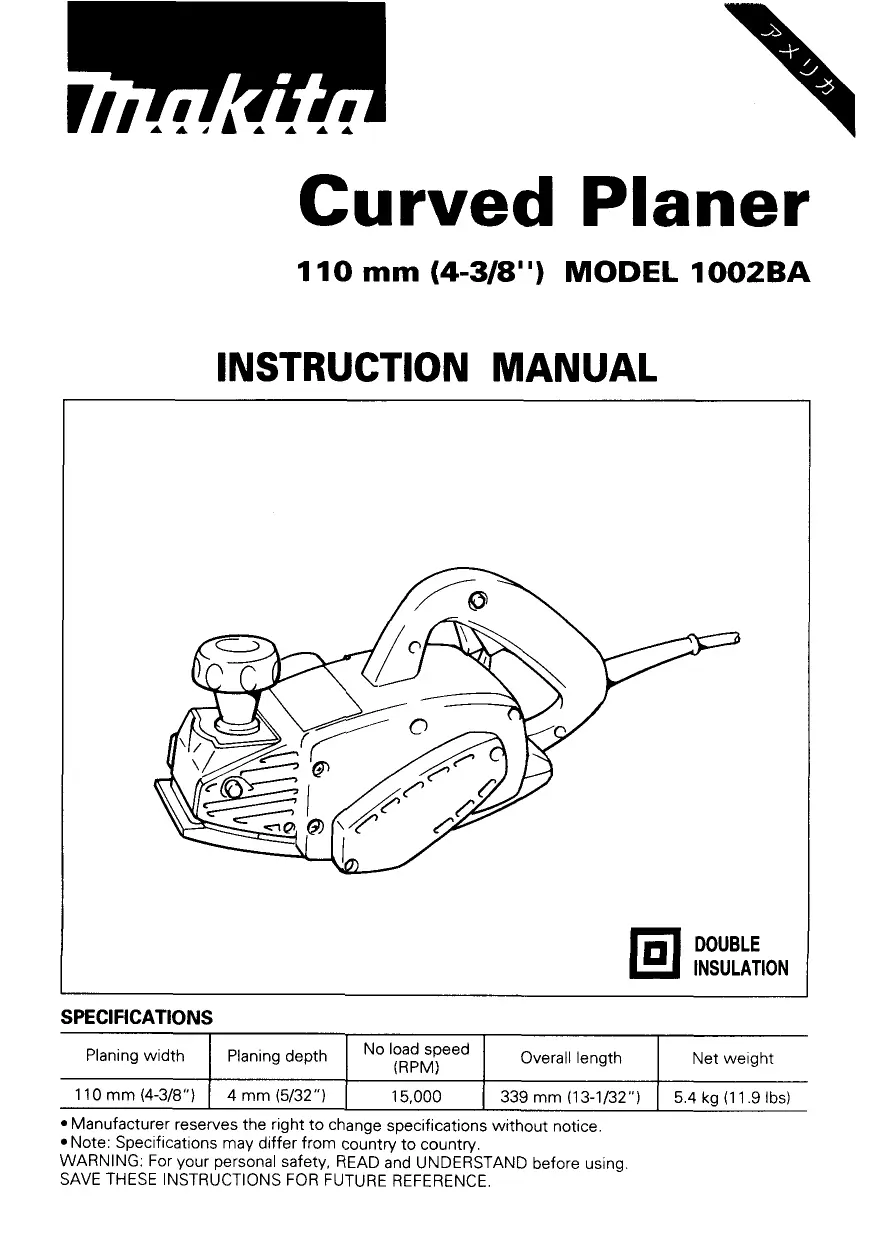
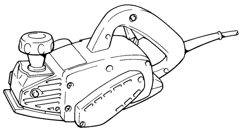
Curved Planer
110 mm (4-3/8") MODEL 1002BA
INSTRUCTION MANUAL

DOUBLE INSULATION
SPECIFICATIONS
| Planing width | Planing depth | No load speed (RPM) | Overall length | Net weight |
| 110 mm (4-3/8") | 4 mm (5/32") | 15,000 | 339 mm (13-1/32") | 5.4 kg (11.9 lbs) |
- Manufacturer reserves the right to change specifications without notice.
Note: Specifications may differ from country to country.
WARNING: For your personal safety, READ and UNDERSTAND before using.
SAVE THESE INSTRUCTIONS FOR FUTURE REFERENCE.
IMPORTANT SAFETY INSTRUCTIONS (For All Tools)
WARNING: WHEN USING ELECTRIC TOOLS, BASIC SAFETY PRECAUTIONS SHOULD ALWAYS BE FOLLOWED TO REDUCE THE RISK OF FIRE, ELECTRIC SHOCK, AND PERSONAL INJURY, INCLUDING THE FOLLOWING:
READ ALL INSTRUCTIONS.
- KEEP WORK AREA CLEAN. Cluttered areas and benches invite injuries.
- CONSIDER WORK AREA ENVIRONMENT. Don't use power tools in damp or wet locations. Keep work area well lit. Don't expose power tools to rain. Don't use tool in presence of flammable liquids or gases.
- KEEP CHILDREN AWAY. All visitors should be kept away from work area. Don't let visitors contact tool or extension cord.
- STORE IDLE TOOLS. When not in use, tools should be stored in dry, and high or locked-up place – out of reach of children.
- DON'T FORCE TOOL. It will do the job better and safer at the rate for which it was intended.
- USE RIGHT TOOL. Don't force small tool or attachment to do the job of a heavy-duty tool. Don't use tool for purpose not intended; for example, don't use circular saw for cutting tree limbs or logs.
- DRESS PROPERLY. Don't wear loose clothing or jewelry. They can be caught in moving parts. Rubber gloves and non-skid footwear are recommended when working outdoors. Wear protective hair covering to contain long hair.
- USE SAFETY GLASSES. Also use face or dust mask if cutting operation is dusty.
- DON'T ABUSE CORD. Never carry tool by cord or yank it to disconnect from receptacle. Keep cord from heat, oil, and sharp edges.
- SECURE WORK. Use clamps or a vise to hold work. It's safer than using your hand and it frees both hands to operate tool.
- DON'T OVERREACH. Keep proper footing and balance at all times.
- MAINTAIN TOOLS WITH CARE. Keep tools sharp and clean for better and safer performance. Follow instructions for lubricating and changing accessories. Inspect tool cords periodically and if damaged, have repaired by authorized service facility. Inspect extension cords periodically and replace if damaged. Keep handles dry, clean, and free from oil and grease.
-
DISCONNECT TOOLS. When not in use, before servicing, and when changing accessories, such as blades, bits, cutters.
-
REMOVE ADJUSTING KEYS AND WRENCHES. Form habit of checking to see that keys and adjusting wrenches are removed from tool before turning it on.
- AVOID UNINTENTIONAL STARTING. Don't carry tool with finger on switch. Be sure switch is OFF when plugging in.
- EXTENSION CORDS. Make sure your extension cord is in good condition. When using an extension cord, be sure to use one heavy enough to carry the current your product will draw. An undersized cord will cause a drop in line voltage resulting in loss of power and overheating. Table 1 shows the correct size to use depending on cord length and nameplate ampere rating. If in doubt, use the next heavier gage. The smaller the gage number, the heavier the cord.
TABLE 1 MINIMUM GAGE FOR CORD SETS
| Total Length of Cord in Feet | ||||||
| 0 — 25 | 25 — 50 | 51 — 100 | 101 — 150 | |||
| Ampere Rating | AWG | |||||
| More Than | Not More Than | |||||
| 0 | — | 6 | 18 | 16 | 16 | 14 |
| 6 | — | 10 | 18 | 16 | 14 | 12 |
| 10 | — | 12 | 16 | 16 | 14 | 12 |
| 12 | — | 16 | 14 | 12 | Not Recommended | |
- OUTDOOR USE EXTENSION CORDS. When tool is used outdoors, use only extension cords intended for use outdoors and so marked.
- STAY ALERT. Watch what you are doing, use common sense. Don't operate tool when you are tired.
- CHECK DAMAGED PARTS. Before further use of the tool, a guard or other part that is damaged should be carefully checked to determine that it will operate properly and perform its intended function. Check for alignment of moving parts, binding of moving parts, breakage of parts, mounting, and any other conditions that may affect its operation. A guard or other part that is damaged should be properly repaired or replaced by an authorized service center unless otherwise indicated elsewhere in this instruction manual. Have defective switches replaced by authorized service center. Don't use tool if switch does not turn it on and off.
- GUARD AGAINST ELECTRIC SHOCK. Prevent body contact with grounded surfaces. For example; pipes, radiators, ranges, refrigerator enclosures.
- REPLACEMENT PARTS. When servicing, use only identical replacement parts.
- POLARIZED PLUGS. To reduce the risk of electric shock, this equipment has a polarized plug (one blade is wider than the other). This plug will fit in a polarized outlet only one way. If the plug does not fit fully in the outlet, reverse the plug. If it still does not fit, contact a qualified electrician to install the proper outlet. Do not change the plug in any way.
VOLTAGE WARNING: Before connecting the tool to a power source (receptacle, outlet, etc.) be sure the voltage supplied is the same as that specified on the nameplate of the tool. A power source with voltage greater than that specified for the tool can result in SERIOUS INJURY to the user – as well as damage to the tool. If in doubt, DO NOT PLUG IN THE TOOL. Using a power source with voltage less than the nameplate rating is harmful to the motor.
ADDITIONAL SAFETY RULES
- Rags, cloth, cord, string and the like should never be left around the work area.
- Avoid cutting nails. Inspect for and remove all nails from the workpiece before operation.
- Handle the blades very carefully.
- Be sure the blade installation bolts are securely tightened before operation.
- Hold the tool firmly with both hands.
- Keep hands away from rotating parts.
- Before using the tool on an actual workpiece, let it run for a while. Watch for vibration or wobbling that could indicate poor installation or a poorly balanced blade.
- Make sure the blade is not contacting the workpiece before the switch is turned on.
- Wait until the blade attains full speed before cutting.
- Keep at least 200 mm (8") away from the tool at all times.
- Always switch off and wait for the blades to come to a complete stop before any adjusting.
- Never stick your finger into the chip chute. Chute may jam when cutting damp wood. Clean out chips with a stick.
- Do not leave the tool running. Operate the tool only when hand-held.
- When leaving the planer, switch off and set it with the front base up on a wooden block, so that the blades do not contact anything.
- Always change both blades or covers on the drum, otherwise the resulting imbalance will cause vibration and shorten tool life.
SAVE THESE INSTRUCTIONS.
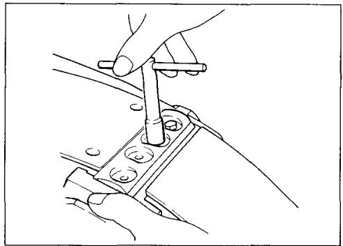
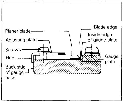
Removing or installing planer blades
CAUTION:
Always be sure that the tool is switched off and unplugged before removing or installing the blade.
To remove the blades on the drum, unscrew the four installation bolts with the socket wrench. The drum cover comes off together with the blades.
To install the blades, first clean out all chips or foreign matter adhering to the drum or blades. Use blades of the same dimensions and weight, or drum oscillation/vibration will result, causing poor planing action and eventually tool breakdown.
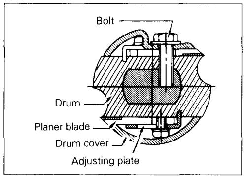
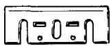
Place the blade on the gauge base so that the blade edge is perfectly flush with the inside edge of the gauge plate. Place the adjusting plate on the blade, then simply press in the heel of the adjusting plate flush with the back side of the gauge base and tighten two screws on the adjusting plate. Now slip the heel of the adjusting plate into the drum groove, then fit the drum cover on it. Tighten the three installation bolts evenly and alternately with the socket wrench.
CAUTION:
Tighten the blade installation bolts carefully when attaching the blades to the tool. A loose installation bolt can be dangerous. Always check to see they are tightened securely.
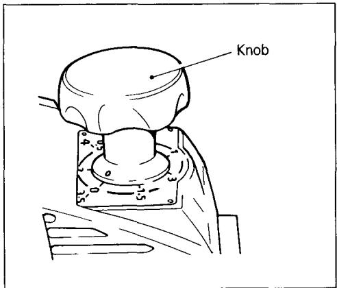
Adjusting depth of cut
Depth of cut may be adjusted by simply turning the knob on the front of the tool.
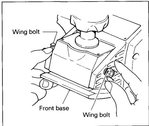
Adjusting front base
The front base is factory-adjusted to allow concave cuts with a radius of 320~mm . For concave cuts with the tool's minimum radius of 300~mm , loosen the wing bolt on either side and raise the front base as far as it will go. Then retighten the two wing bolts firmly to secure the front base.
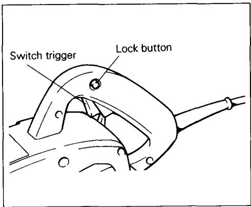
Switch action
To start the tool, simply pull the trigger. Release the trigger to stop. For continuous operation, pull the trigger and then push in the lock button. To stop the tool from the locked position, pull the trigger fully, then release it.
CAUTION:
Before plugging in the tool, always check to see that the switch trigger actuates properly and returns to the "OFF" position when released.
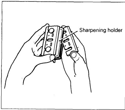
Sharpening planer blades
Always keep your blades sharp for the best performance possible. Use the sharpening holder to remove nicks and produce a fine edge.
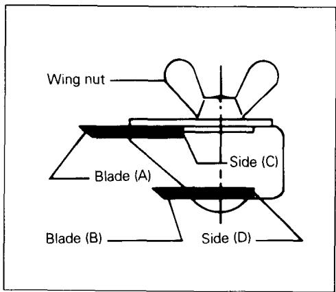
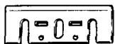
First, loosen the two wing nuts on the holder and insert the blades (A) and (B), so that they contact the sides (C) and (D). Then tighten the wing nuts.
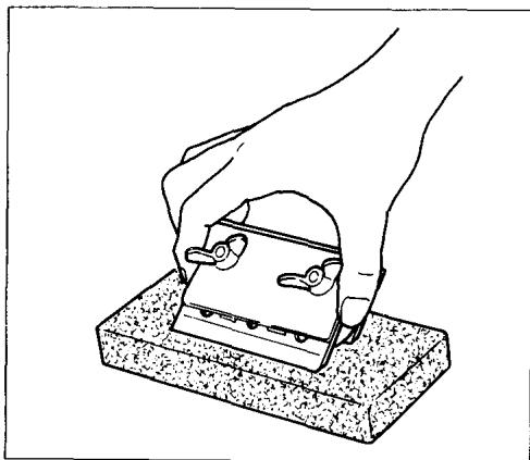
Immerse the dressing stone in water for 2 or 3 minutes before sharpening. Hold the holder so that the blades both contact the dressing stone for simultaneous sharpening at the same angle.
MAINTENANCE
CAUTION:
Always be sure that the tool is switched off and unplugged before attempting to perform inspection or maintenance.
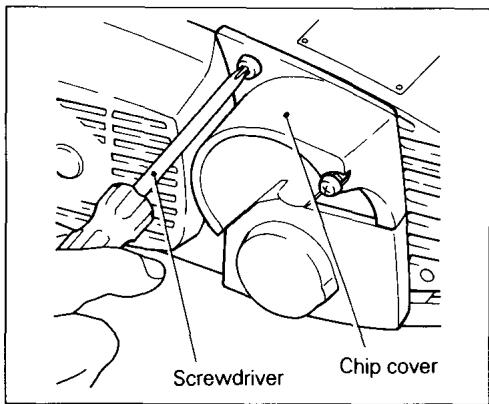
Replacing carbon brushes
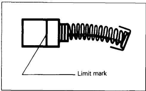
Remove and check the carbon brushes regularly. Replace when they wear down to the limit mark. Keep the carbon brushes clean and free to slip in the holders. Both carbon brushes should be replaced at the same time. Use only identical carbon brushes.
Use a screwdriver to remove the chip cover.
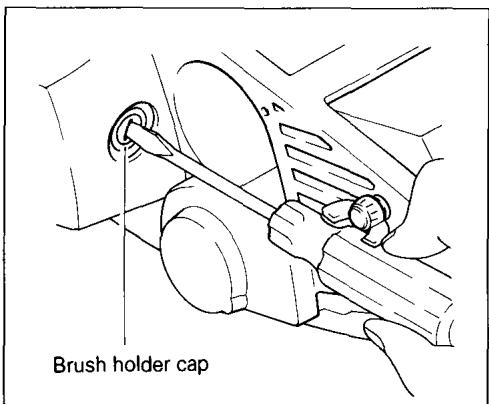
Use a screwdriver to remove the brush holder caps. Take out the worn carbon brushes, insert the new ones and secure the brush holder caps.
To maintain product SAFETY and RELIABILITY, repairs, any other maintenance or adjustment should be performed by Makita Authorized or Factory Service Centers, always using Makita replacement parts.
ACCESSORIES
CAUTION:
These accessories or attachments are recommended for use with your Makita tool specified in this manual. The use of any other accessories or attachments might present a risk of injury to persons. The accessories or attachments should be used only in the proper and intended manner.
- Planer blade
Width: 110 mm (4-3/8")
Part No. 793008-8
- Planer blade
(Material: Tungsten-carbide)
Width: 110 mm (4-3/8")
Part No. 793009-6
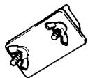
- Sharpening holder assembly
Part No. 123055-9
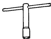
- Socket wrench
Part No. 782209-3
- Blade gauge
Part No. 123062-2
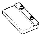
110 mm (4-3/8")
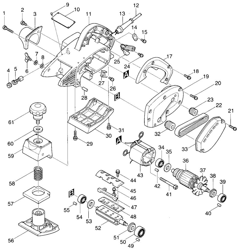
CURVED PLANER
Model 1002BA
Note: The switch and other part configurations may differ from country to country.
ITEM
NO.
NO.
USED
DESCRIPTION
ITEM
NO. USED
NO.
1
DESCRIPTION
MACHINE
MACHINE
| 1 | 1 | Pan Head Screw M4x50 | 33 | 1 | Belt Cover |
| 2 | 1 | Pan Head Screw M4x20 | 34 | 1 | Ball Bearing 6200LB |
| 3 | 1 | Chip Cover | 35 | 1 | Insulation Washer |
| 4 | 2 | Brush Holder Cap | 36 | 1 | ARMATURE ASSEMBLY(With Item 34, 35, 38 & 39) |
| 5 | 2 | Carbon Brush | |||
| 6 | 2 | Wing Bolt M6x25 | 38 | 1 | Flat Washer 12 |
| 7 | 2 | Spring Washer 6 | 39 | 1 | Ball Bearing 6201DDW |
| 8 | 2 | Flat Washer 6 | 40 | 1 | Rubber Pin 6 |
| 9 | 4 | Rivet 0-5 | 41 | 2 | Pan Head Screw M5x65 |
| 10 | 1 | Name Plate | 42 | 1 | Rubber Pin 4 |
| 11 | 1 | Main Frame | 43 | 1 | FIELD ASSEMBLY |
| 12 | 1 | Cord | 44 | 8 | Hex. Flange Head Bolt M6x17 |
| 13 | 1 | Cord Guard | 45 | 2 | Drum Plate |
| 14 | 1 | Strain Relief | 46 | 4 | Pan Head Screw M4x5 |
| 15 | 2 | Pan Head Screw M4x18 | 47 | 2 | Adjusting Plate |
| 17 | 1 | Handle Cover | 48 | 2 | Planer Blade 110 |
| 18 | 3 | Pan Head Screw M4x30 | 49 | 1 | Rubber Pin 6 |
| 19 | 1 | Bracket (With Item 40 & 49) | 50 | 1 | Ball Bearing 6201ZZ |
| 20 | 6 | Pan Head Screw M5x28 | 51 | 1 | Washer 12 |
| 21 | 2 | Pan Head Screw M4x30 | 52 | 1 | Drum |
| 22 | 1 | Poly V-Belt 6-272 | 53 | 1 | Washer 10 |
| 23 | 1 | V-Pulley 6-23L | 54 | 1 | Ball Bearing 6200ZZ |
| 24 | 2 | Pan Head Screw M4x6 | 55 | 1 | Rubber Pin 4 |
| 25 | 1 | Switch | 56 | 1 | Front Base |
| 26 | 1 | Pan Head Screw M4x12 | 57 | 1 | Rubber Packing |
| 27 | 1 | Fan Guide | 58 | 1 | Compression Spring 21 |
| 28 | 2 | Pin 6 | 59 | 1 | Front Box |
| 29 | 2 | Pan Head Screw M5x28 | 60 | 1 | Flat Washer 13 |
| 30 | 1 | Base | 61 | 1 | Knob 64 |
| 31 | 2 | Pan Head Screw M5x18 | 62 | 1 | Label |
| 32 | 1 | V-Pulley 6-30 |
Note: The switch and other part specifications may differ from country to country.
MAKITA LIMITED ONE YEAR WARRANTY
Warranty Policy
Every Makita tool is thoroughly inspected and tested before leaving the factory. It is warranted to be free of defects from workmanship and materials for the period of ONE YEAR from the date of original purchase. Should any trouble develop during this one-year period, return the COMPLETE tool, freight prepaid, to one of Makita's Factory or Authorized Service Centers. If inspection shows the trouble is caused by defective workmanship or material, Makita will repair (or at our option, replace) without charge.
This Warranty does not apply where:
- repairs have been made or attempted by others:
- repairs are required because of normal wear and tear:
- The tool has been abused, misused or improperly maintained;
- alterations have been made to the tool.
IN NO EVENT SHALL MAKITA BE LIABLE FOR ANY INDIRECT, INCIDENTAL OR CONSEQUENTIAL DAMAGES FROM THE SALE OR USE OF THE PRODUCT. THIS DISCLAIMER APPLIES BOTH DURING AND AFTER THE TERM OF THIS WARRANTY.
MAKITA DISCLAIMS LIABILITY FOR ANY IMPLIED WARRANTYES, INCLUDING IMPLIED WARRANTYES OF "MERCHANTABILITY" AND "FITNESS FOR A SPECIFIC PURPOSE," AFTER THE ONE-YEAR TERM OF THIS WARRANTY.
This Warranty gives you specific legal rights, and you may also have other rights which vary from state to state. Some states do not allow the exclusion or limitation of incidental or consequential damages, so the above limitation or exclusion may not apply to you. Some states do not allow limitation on how long an implied warranty lasts, so the above limitation may not apply to you.
Makita Corporation
3-11-8, Sumiyoshi-cho,
Anjo, Aichi 446 Japan


- Curved Planer
- INSTRUCTION MANUAL
- IMPORTANT SAFETY INSTRUCTIONS (For All Tools)
- READ ALL INSTRUCTIONS.
- ADDITIONAL SAFETY RULES
- SAVE THESE INSTRUCTIONS.
- Removing or installing planer blades
- CAUTION:
- Adjusting depth of cut
- Adjusting front base
- Switch action
- Sharpening planer blades
- MAINTENANCE
- Replacing carbon brushes
- ACCESSORIES
- - Planer blade
- - Sharpening holder assembly
- - Socket wrench
- - Blade gauge
- mm (4-3/8")
- Model 1002BA
- MAKITA LIMITED ONE YEAR WARRANTY
Marque : MAKITA
Modèle : 1002BA
Catégorie : Raboteuse électrique