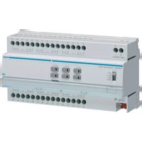
TYM632C - Automatisme électrique HAGER - Notice d'utilisation et mode d'emploi gratuit
Retrouvez gratuitement la notice de l'appareil TYM632C HAGER au format PDF.


| Type de produit | Dispositif de commande et de protection électrique |
| Marque | Hager |
| Modèle | TYM632C |
| Dimensions (L x H x P) | 36 mm x 80 mm x 70 mm (2 modules) |
| Poids | 150 g |
| Alimentation | 230 V AC, 50 Hz |
| Courant nominal | 16 A |
| Pouvoir de coupure | 6 kA |
| Nombre de pôles | 1P + N |
| Type de courbe de déclenchement | C |
| Fonctions principales | Protection contre les surcharges et courts-circuits, commande manuelle marche/arrêt |
| Température de fonctionnement | -25 °C à +55 °C |
| Indice de protection | IP20 (selon montage en tableau) |
| Matériau du boîtier | Polyamide auto-extinguible |
| Montage | Sur rail DIN (EN 60715) |
| Connexion électrique | Bornes à vis (section max 16 mm²) |
| Entretien et nettoyage | Nettoyer avec un chiffon sec, hors tension |
| Sécurité | Respecter les normes électriques en vigueur, installation par un professionnel |
| Pièces détachées et réparabilité | Pièces disponibles auprès du service après-vente Hager |
| Informations générales | Notice d'utilisation de 2 pages (téléchargeable au format PDF) |
FOIRE AUX QUESTIONS - TYM632C HAGER
Questions des utilisateurs sur TYM632C HAGER
0 question sur cet appareil. Repondez a celles que vous connaissez ou posez la votre.
Poser une nouvelle question sur cet appareil
Téléchargez la notice de votre Automatisme électrique au format PDF gratuitement ! Retrouvez votre notice TYM632C - HAGER et reprennez votre appareil électronique en main. Sur cette page sont publiés tous les documents nécessaires à l'utilisation de votre appareil TYM632C de la marque HAGER.
MODE D'EMPLOI TYM632C HAGER

TYM632C
Output 12gang shutter/blind 230V\~
TXM632C
Output 12gang shutter/blind 230V\~


Safety instructions
EN
Electrical equipment may only be installed and assembled by a qualified electrician in accordance with the relevant installation standards, guidelines, regulations, directives, safety and accident prevention regulations of the country.
Failure to comply with these installation instructions may result in damage to the device, fire or other hazards.
Hazard due to electric shock. Disconnect before working on the device or load. Take into account all circuit breakers that supply dangerous voltages to the device or load.
Connect one motor per output only. If several motors are connected, motors or device might be destroyed.
Use drives with mechanical or electrical final position switches only. Check final position switches for correct adjustment. Observe motor manufacturer's data. The device can be damaged.
Do not connect any three-phase motors. The device can be damaged.
Risk of injury. Use the device to control blind and shutter drives or awnings only. Do not switch any other loads.
Observe the motor manufacturer's data regarding change-over time and max. switch-on time (ED).
These instructions are an integral component of the product and must be retained by the end user.
Design and layout of the device
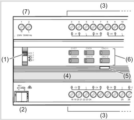
Figure 1: Device overview

(1) Slide switch auto1/auto2/ €2
(2) KNX bus connection terminal
(3) Connections of loads
(4) Labelling field with cover
(5) Illuminated programming button
(6) Operation button for manual operation per output with status LED
(7) Mains power supply connection
Function
System information
This device is a product of the KNX system and corresponds to the KNX guidelines. Detailed specialised knowledge obtained from KNX training courses
is required for understanding. The planning, installation and commissioning of the device is carried out with the help of KNX-certified software.
Systemlink commissioning:
The function of the device is software-dependent. The software is to be taken from the product database. You can find the latest version of the product database, technical descriptions as well as conversion and additional support programmes on our website.
Easylink commissioning:
The function of the device is configuration-dependent. The configuration can also be done using devices developed specially for simple setting and start-up.
This type of configuration is only possible with devices of the easylink system. Easylink stands for easy, visually supported start-up. Preconfigured standard functions are assigned to the in/outputs by means of a service module.
Functional description
The device is used to control motor-operated building fittings such as shutters and blinds via the KNX bus. The device has 12 outputs from which each output can be activated independently.
Correct use
- Switching electrically operated motors of 230 V AC for blinds, shutters, awnings and similar hangings
- Mounting on DIN rail according to DIN EN 60715 in the distribution box
Product characteristics
- independent outputs, activation via KNX bus
- Status display of the outputs on the device
- manual activation of the outputs on the device possible, building site operation
- Position can be started directly
- 3 Alarms
- Scene function
- Forced position by higher-level controller - Connection of various external conductors possible - Slat position directly controllable
Operation
Manual operation switch on/off
Bus and mains power supply are present.
- Push switch (1) to position 1/2
Manual operation is switched on, the outputs can be controlled using the operation buttons (6) independently of each other.
1 switches on the control of the outputs C1 .. C6.
2 switches on the control of the outputs C7 .. C12.
During manual operation, the controller is deactivated via the KNX bus.
ystemlink commissioning:
Depending on the programming, the manual operation is activated permanently or for a time period configured via the application software. If the manual operation is blocked via the application software, no activation takes place.
Or:
- Move switch (1) to position auto1/auto2.
The manual operation is switched off. Operation takes place solely via the KNX bus. The output adopts the position predefined by the bus controller. The switching status is displayed via the status LED of the operation button (6).
auto 1 displays the status of the outputs C1 .. C6.
auto 2 displays the status of the outputs C7 .. C12.
Operating outputs in manual operation
Operation takes place per output by briefly pressing the operation button repeatedly (table1).
| Status Behaviour | when button pressed briefly |
| Output is in idle state, status LED of the button (6) is off. | Movement operation starts. Status LED of button (6) lights up. 1) |
| Output active, status LED of the button (6) lights up. 1) | Movement operation stops, LED goes out. |
1) The LED lights up red during upward travel and green during downward travel.
Table 1: Manual operation
Information for electricians
Installation and electrical connection

DANGER!
Touching live parts can result in an electric shock!
An electric shock can be lethal!
Disconnect the connecting cables before working on the device and cover all live parts in the area!

CAUTION!
Risk of destruction if parallel connection of several motors on one output!
Final position switches could fuse together. Motors, hangings and the device may be destroyed!
Only connect one motor per output!
Installing the appliance
Observe temperature range. Provide sufficient cooling.
- Mount device onto DIN rail in accordance with DIN EN 60715.
Connecting the device (Figure 2)
The installation circuit must be protected via circuit breaker 10 A.
- Connect bus cable via connecting terminal (2).
- Connect mains voltage (7).
- Connect motors.
Start-up
Systemlink: Loading physical address and application software
The switch (1) is in auto1/auto2.
- Switch on bus voltage.
- Press programming button (5).
The button lights up.
the button does not light up, no bus voltage is present.
- Load the physical address into the device.
Status LED of the button goes out. - Load application software.
- Note down the physical address on the labelling field (4).
Easylink:
Information on the system configuration can be taken from the extensive description of the service module easylink.
Starting up the device
- Switch on mains voltage on the outputs.
- Switch on mains supply.
[Non-Text]
[Non-Text]
Determine operation time and slat adjusting time
In blind/roller shutter operation, the operation time for positioning the sunshade is important. The position is calculated based on the operation time. The slat adjusting time for slat blinds, determined by the design, is part of the total operation time. The opening angle of the slats is therefore set as operation time between opened and closed position.
The operation time for UP is normally longer than the operation time for DOWN and must be measured separately if necessary.
● Measure UP and DOWN operation time of the hanging.
● Measure slat adjusting time between OPEN and CLOSED.
- Enter measured values into the parameter setting – running time... or slat step time.
Functional test
The functionality of the outputs is displayed via the status LED of the operation button (6).
Appendix
Technical data
KNX medium TP 1
Configuration mode S-Mode, E-controller
easy link
Rated voltage KNX 30 V --- SELV
Own consumption on the KNX bus:
- typical 7 mA - in standby 5 mA
Auxiliary voltage 230V\~ +10%/-15%
240V\~+/-6%
Mains frequency 50/60 Hz
Power dissipation maximum 3 W
Own consumption on mains:
- maximum 5 W - in standby 0.2 W
Breaking capacity µ 4A AC1 230V\~
Switching current at cos Φ = 0.6 max. 4 A
Upstream protection: circuit breaker 10 A
Operating altitude max. 2000 m
Degree of contamination 2
Surge voltage 4 kV
Degree of protection of housing IP 20
Degree of protection of housing
under front panel IP30
Impact protection IK 04
Overvoltage class III
Operating temperature -5°C à +45°C
Storage/transport temperature -20°C à +70°C
Maximum switching cycle
rate at full load 6 switching cycle/minute
Connection capacity 0.5 mm 2 ... 6 mm 2
Dimension 10 TE, 10 x 17.5 mm
Troubleshooting
Manual operation not possible
Cause 1: Switch (1) not moved to €/2.
Move switch to €1/2.
Cause 2: Manual operation has not been enabled (Systemlink).
Enable manual operation via application software.
Bus operation is not possible
Cause: Bus voltage is not present.
Check bus connection terminal for correct polarity.
Check bus voltage by briefly pressing the programming button (5), red LED lights up if bus voltage is present.
If mains voltage is available without bus voltage - red LED of the programming button (5) blinks.
Cause 2 : Manual operation is active. Switch (1) is in position 1/2.
Move switch (1) to position auto1/auto1.
Shutters/blinds do not move to the final position
Cause: Operation time for the shutters/blinds set incorrectly.
Check operation times. Measure again and reprogram if necessary.

Correct Disposal of This product (Waste Electrical & Electronic Equipment).
(Applicable in the European Union and other European countries with separate collection systems).
This marking shown on the product or its literature indicates that it should not be disposed with other household wasted at the end of its working life. To prevent possible harm to the environment or human health from uncontrolled waste disposal, please separate this from other types of wastes and recycle it responsibly to promote the sustainable reuse of material resources.
Household users should contact either the retailer where they purchased this product, or their local government office, for details of where and how they can take this item for environmentally safe recycling.
Business users should contact their supplier and check the terms and conditions of the purchase contract. This product should not be mixed with other commercial wastes of disposal.
Usable in all Europe C€ and in Switzerland
- TYM632C
- TXM632C
- SAFETY INSTRUCTIONS
- FUNCTION
- SYSTEM INFORMATION
- SYSTEMLINK COMMISSIONING
- EASYLINK COMMISSIONING
- FUNCTIONAL DESCRIPTION
- CORRECT USE
- PRODUCT CHARACTERISTICS
- OPERATION
- MANUAL OPERATION SWITCH ON/OFF
- OPERATING OUTPUTS IN MANUAL OPERATION
- INFORMATION FOR ELECTRICIANS
- INSTALLATION AND ELECTRICAL CONNECTION
- DANGER
- CAUTION
- INSTALLING THE APPLIANCE
- CONNECTING THE DEVICE (FIGURE 2)
- START-UP
- SYSTEMLINK: LOADING PHYSICAL ADDRESS AND APPLICATION SOFTWARE
- EASYLINK
- STARTING UP THE DEVICE
- DETERMINE OPERATION TIME AND SLAT ADJUSTING TIME
- FUNCTIONAL TEST
- APPENDIX
- TECHNICAL DATA
- TROUBLESHOOTING
- MANUAL OPERATION NOT POSSIBLE
- BUS OPERATION IS NOT POSSIBLE
- SHUTTERS/BLINDS DO NOT MOVE TO THE FINAL POSITION
Marque : HAGER
Modèle : TYM632C
Catégorie : Automatisme électrique