RT144 - Radio SAILOR - Notice d'utilisation et mode d'emploi gratuit
Retrouvez gratuitement la notice de l'appareil RT144 SAILOR au format PDF.


| Type de produit | Radio VHF marine fixe |
| Marque | Sailor |
| Modèle | RT144 |
| Dimensions (L x H x P) | 250 x 150 x 80 mm |
| Poids | 1,2 kg |
| Alimentation | 12 V CC (2,5 A max) |
| Gamme de fréquences | 156-174 MHz (bande marine VHF) |
| Canaux | 55 canaux marins internationaux, 10 météo |
| Fonctions principales | Émission/réception VHF, appel sélectif numérique (DSC), double veille, balayage de canaux, affichage LCD rétroéclairé |
| Puissance d'émission | 25 W (réglable 1 W/25 W) |
| Réceptivité | Moins de 0,5 µV (SINAD 20 dB) |
| Température de fonctionnement | -20 °C à +55 °C |
| Indice de protection | IPX7 (immersion temporaire) |
| Entretien et nettoyage | Essuyer avec un chiffon doux et humide ; éviter les solvants |
| Sécurité | Ne pas utiliser dans une atmosphère explosive ; éteindre en zone de ravitaillement |
| Pièces détachées et réparabilité | Antenne, micro, câble d'alimentation, fusibles ; réparation par centre agréé Sailor |
| Informations générales | Notice de 60 pages disponible en téléchargement ; conforme aux normes maritimes |
FOIRE AUX QUESTIONS - RT144 SAILOR
Questions des utilisateurs sur RT144 SAILOR
0 question sur cet appareil. Repondez a celles que vous connaissez ou posez la votre.
Poser une nouvelle question sur cet appareil
Téléchargez la notice de votre Radio au format PDF gratuitement ! Retrouvez votre notice RT144 - SAILOR et reprennez votre appareil électronique en main. Sur cette page sont publiés tous les documents nécessaires à l'utilisation de votre appareil RT144 de la marque SAILOR.
MODE D'EMPLOI RT144 SAILOR

natural_image
Geometric compass design with six black star-like shapes and a fleur-de-lis symbol at the top (no text or labels)Sailor
Sailor
INSTRUKTIONSBOG FOR SAILOR RT144
INSTRUCTION BOOK FOR SAILOR RT144
INSTRUKTIONSBUCH FÜR SAILOR RT144
INSTRUCTIONS POUR SAILOR RT144
INSTRUCCIONES PARA SAILOR RT144

A/S S. P. RADIO · AALBORG · DENMARK
GENERAL DESCRIPTION
Introduction
SAILOR RT144 is a telecommunication set comprising a transmitter and a receiver for simplex and semi-duplex VHF-radiocommunication on the international maritime VHF-channels.
SAILOR RT144 is a multi-channel set incorporating all international VHF-channels.
SAILOR RT144 is prepared for up to five private channels to be selected as simplex or semi-duplex channels in the frequency band 155,0 - 163,2 MHz.
SAILOR RT144 makes use of a digital synthesizer for frequency generation. The VHF-transceiver is provided with only one crystal to control all international maritime VHF-channels and the five optional private channels.
SAILOR RT144 is provided with a new and simple programming system which increases the reliability besides giving the station an unsurpassed flexibility as far as complying with all requirements from authorities and customers is concerned.
SAILOR RT144 is designed for installation in vessels of any type. The set is of all transistor design, and consequently the power consumption is very modest, and at the same time it has been possible to secure a very rugged construction.
SAILOR RT144 is built in an all-welded steel cabinet with antirust surfaces and Nylon finish in green colour. The control knobs are of deformation-resistant plastic material.
SAILOR RT144 is built up of modules and these are placed on swing chassis to facilitate service and repairs.
SAILOR RT144 can be delivered as 12 Volt or 24 Volt VHF-transceivers. The voltage changeover from 12 Volt to 24 Volt can be done by mounting a 24 Volt regulator on the back of the VHF-transceiver. This is a simple modification which can be made without dismounting the VHF-transceiver.
CONTENTS
General Description.... 1
Technical Data RT144 4
Controls 5
Installation 6
Mounting....6
Handset.... 6
Power Supply 7
Auxiliary Loudspeaker 7
Antennas 7
Principle of Operation 8
Circuit Description 10
Rx-Amplifier-Unit 10
Audio-Amplifier-Unit 11
Supply-Unit 12
Oscillator-Unit 13
Divider-Unit 14
Harmonic-Filter 15
Tx-Power-Amplifier 16
Tx-Exciter-Unit 17
Microphone Pre-Amplifier 18
Programming of Private Channels.... 19
Frequency Table 21
Normal Installation with 1 Microtelephone 25
Special Installation with 2 Microtelephones.... 25
Mechanical layouts 26
Service 28
Maintenance 28
Alignment Instruction 28
Adjustment Procedure.... 29
Trouble-Shooting 33
Trouble-Shooting in the frequency generating circuit 33
Replacement of Module 34
Replacement of Component 34
Necessary Adjustment after replacement of Module 34
Functional Block Diagrams for the Integrated Circuits.... 35
Pin Configuration 37
Main Diagram:
Part Lists:
TECHNICAL DATA RT144
General
All international maritime channels.
Private channels 5 pcs.
Channel separation 25 kHz
Modulation .... Phase
Operation ...... Simplex and semi-duplex
Temperature range -20°C to +55°C
Frequency stability ±10 ppm (±1,5 kHz)
Antenna impedance 50 ohm
Power supply 12 Volt DC or 24 Volt DC
Power consumption.... Stand-by = 0,5 Amp.
Transmit = 5 Amp.
Voltage variation -10% +30%
(with reduced data after international specs.)
Dimensions ...... Height = 220 mm
Width = 320 mm
Depth = 165 mm
Weight 9 kg
Receiver
Frequency range simplex.... 155,000 - 158,600 MHz
Frequency range semi-duplex ..... 159,600 - 163,200 MHz
Sensitivity 0,25 uV PD for 12 dB SINAD
AF-output power 2,5 Watt/4 ohm
Distortion .... less than 5%
Transmitter
Frequency range normal 155,00 - 158,600 MHz
Frequency range special.... 159,600 - 163,200 MHz
RF-output power 25 Watt
Reduced RF-output power .... 1 Watt
Distortion ....less than 5%
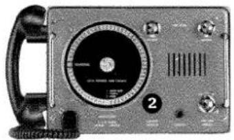
CONTROLS

natural_image
Front view of a vintage analog oscilloscope device with a circular dial and control knobs (no visible text or symbols)1 FUNCTION SWITCH
OFF: The set is switched off.
ON: The set is switched on and ready for use immediately.
1W: Transmitter output reduced to 1 Watt (for use in heavily used waters).
2
CHANNEL SELECTOR
By means of the channel selector the required channel number is selected.
natural_image
Front view of a vintage telephone receiver with dial and control knobs (no visible text or symbols)3
VOLUME
Continuous volume control.

natural_image
Front view of a vintage analog oscilloscope with dial and control knobs (no visible text or symbols)4
SQUELCH
The squelch has to be adjusted by turning the knob clockwise, until the white noise in the loudspeaker just disappears. The adjustment must be done without receiving a signal.

natural_image
Close-up of a silver analog oscilloscope with a dial and control knobs (no visible text or symbols)5
DIMMER
Brightness control in channel indicator.

natural_image
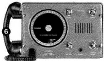
Front view of a vintage analog oscilloscope with a circular dial and control knobs (no visible text or symbols)6
HANDSET
When the handset key is pressed, the transmitter is started.
When the handset key is not pressed, all calls will be heard in the loudspeaker.
natural_image
Close-up of a vintage analog oscilloscope with a dial and control knobs (no visible text or symbols)7
LOUDSPEAKER
All calls are heard like mentioned under handset. Auxiliary loudspeaker may be connected to the power supply plug.

natural_image
Close-up of a vintage analog oscilloscope with a dial and control knobs (no visible text or labels)8
CHANNEL APPLICATION
Showing the use of the selected channel.
INTER SHIP: Ship to ship correspondence.
PORT: Port service.
PUBLIC: Public correspondence.

natural_image
Close-up of a vintage analog oscilloscope with a dial and control knobs (no visible text or symbols)INSTALLATION

Mounting panel


Mounting
It is a very easy matter to install the SAILOR RT 144 telecommunication set in the radio room, on the bridge or anywhere on board.
The mounting panel is fixed to the bulkhead by means of 4 screws. The set is hung up on this, there being 4 hooks on the mounting panel matching 4 slots at the back of the set. Two springloaded locks prevent the set from becoming loose from this mounting panel. If the set has to be taken down, the locks must be pushed in the direction of the arrows, lifting the set simultaneously.
Handset
The handset may be placed at the left side of the VHF set or if it is not suitable anywhere near the set. The cable is five-cored and may be extended. The cable is connected to the front of the VHF-set by means of a connector.

natural_image
Line drawing of a telephone handset with coiled cord and circular button (no text or symbols)
natural_image
Line drawing of a telephone receiver with a coiled cord and control panel (no text or symbols)Possible position of handset
Power Supply
THE SAILOR RT144 can be delivered in two versions; for 12 V DC supply voltage and for 24 V DC supply voltage.
For 110 V AC - 127 V AC - 220 V AC or 237 V AC supply voltage an external power supply N163 must be used. In that case SAILOR RT144 then has to be the 24 V DC version.
Please ascertain that the SAILOR RT144 is set to 12 V or 24 V corresponding to the voltage of the mains of the vessel.
SAILOR RT144 can easily be changed from 24 V power supply to 12 V power supply or vice versa.
SAILOR RT 144 VERSION FOR 12V POWER SUPPLY
SAILOR RT144 VERSION FOR 24V POWER SUPPLY
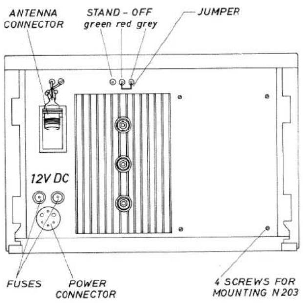

Change from 12 V power supply to 24 V power supply:
Remove the jumper from the STAND OFF's.
Mount the power supply unit N203.
Solder the three WIRES green-red-grey to the corresponding STAND OFF's.
Change from 24 V power supply to 12 V power supply:
Remove the WIRES from the STAND-OFF's.
Remove the power supply unit N203.
Solder a jumper from STAND
OFF marked red to STAND
OFF marked grey.
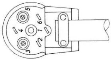
Power connector
VIEW FROM MOUNTING SIDE
PIN 1 Aux. loudspeaker.
PIN 2 No connection.
PIN 3 +12/24V Power supply.
PIN 4 Aux. loudspeaker.
PIN 5-12/24V Power supply.
PIN 6 No connection.
Auxiliary loudspeaker
The auxiliary 8 Ohm loudspeaker may be connected to pin 1 and pin 4 at the power connector.
Remember there is 12 V DC on the loudspeaker wires.
Auxiliary loudspeakers are available.
Antennas
All common 50 ohm antennas, which cover the used frequency range with a reasonable standing wave ratio, maximum 1,5, are applicable.
The antenna is connected to the set by means of a 50 ohm coaxial cable with low loss, e.g. RG8U. At the cable end a PL 259 plug is mounted.
The antenna must be placed as high and as clear as possible. To metal parts the horizontal distance must be at least 0,5 m.
S.P. Radio has an antenna of the necessary specifications available. The mentioned antenna is characterized by small external dimensions. For further particulars see special brochure. VHF AERIALS.
PRINCIPLE OF OPERATION

flowchart
graph TD
    A["RF RMP"] --> B["FIRST MIXER"]
    B --> C["10.7 MHz IF"]
    C --> D["SECOND MIXER"]
    D --> E["400 KHz IF + DETECTOR"]
    E --> F["RF AMP"]
    F --> G["RF - POWER RMP"]
    G --> H["LEAVSPEAKER"]
    H --> I["TELEPHONE"]
    I --> J["RECEIVER"]
    J --> K["INTERNA RELRY"]
    K --> L["AMRONIC FILTER"]
    L --> M["POWER RMP"]
    M --> N["DRIVER RMP"]
    N --> O["BUFFER RMP"]
    O --> P["V.C.D."]
    P --> Q["LOOP FILTER"]
    Q --> R["PURSE/FIREO DETECTOR"]
    R --> S["FREQUENCY GENERATOR"]
    S --> T["MICROPHONE RMP"]
    T --> U["MICROPHONE WITH PRE-RMP TRANSMITTER"]
    U --> V["FIRTS 3NIFT"]
    V --> W["PROGRAM-MING DISC"]
    W --> X["SYNTHESIZER MISER"]
    X --> Y["PROGARMS-BILE DIVIDER N"]
    Y --> Z["DIVIDER N = V/V"]
    Z --> AA["MULTIPLIER x 12"]
    AA --> AB["400 KHz IF + DETECTOR"]
    AB --> AC["SQUELCH"]
    AC --> AD["RF - POWER RMP"]
    AD --> AE["LEAVSPEAKER"]
    AE --> AF["TELEPHONE"]
    AF --> AG["FIREVY GENERATOR"]
    AG --> AH["MUXICLOWER"]
    AH --> AI["INTENNR RELRY"]
    AI --> AJ["Rx-control"]
    AJ --> AK["Rx"]
    AK --> AL["Rx"]
Frequency generation
The necessary frequencies are generated by a frequency synthesizer according to the Phase-Locked-Loop principle.
A voltage-controlled oscillator (VCO) generates the output frequency fvco directly on the requested frequency.
The VCO-frequency can be varied by means of a DC-control-voltage from the PHASE DETECTOR.
The DC-control-voltage is filtered in the LOOP-FILTER.
The PHASE DETECTOR receives two signals, one variable frequency fv and one reference frequency fR. The reference frequency fR is a result of the crystal oscillator frequency 11,1 MHz being divided down to 25 kHz.
f_R=11100 kHz/M=11100 kHz/444 =25 kHz; M=444.
The variable frequency fv is generated from the VCO-frequency in the following way:
In the SYNTHESIZER MIXER the counter frequency fT is produced from the VCO-frequency and the multiplied crystal oscillator frequency.
fT = fvco - (12 x 11,1 MHz) = fvco - 133,2 MHz.
The counter frequency fT is divided down by the dividing figure N in the PROGRAMMABLE DIVIDER to the variable frequency fv.
fV = fT / N = 25kHz.
The working principle in a »Phase-Locked Loop« is the following: If there is a phase error between the variable frequency fv and the reference frequency fR, the regulation system has the characteristic that the DC-control-voltage will correct the VCO-frequency and consequently the variable frequency fv, so that fv will always follow the reference frequency fR in phase.
f_R = f_V = (f_VCO - 133,2 MHz)/N = 25 kHz.
The VCO-frequency is now phase-locked on a fixed frequency to the reference frequency fR and has therefore the same accuracy as this.
Changing of the VCO-frequency by e. g. 25 kHz (one channel) can be performed by changing the dividing figure N in the PROGRAMMABLE DIVIDER by one.
fvCO = 133,2MHz + (Nx0,025MHz)
The VCO-signal is used to feed both transmitter and receiver with the necessary frequencies respectively fTX and fLO. This means that the VCO must generate frequencies in the following four frequency bands.

line
| Frequency (MHz) | Signal Type | |---|---| | 144,3 | Simplex Receive | | 147,9 | Duplex Receive | | 148,9 | Duplex Receive | | 152,5 | Normal Transmit | | 155,0 | Normal Transmit | | 158,6 | Normal Transmit | | 159,6 | Special Transmit | | 163,2 | Special Transmit |The principle of programming is as follows:
The 145 potential frequencies in each band are controlled from the PROGRAMMING DISC, which encodes a start-figure P in the PROGRAMMABLE DIVIDER.
In the PROGRAMMABLE DIVIDER it is possible to encode a stop-figure S for each band. The frequency band is selected from Simplex/Duplex switch - RX/TX switch and Special Transmit switch.
The PROGRAMMABLE DIVIDER contains a counter circuit, which starts counting from the starting figure P and stops at the stop-figure S. Each time the counter reaches the stop-figure S, a pulse (fv) is given to the PHASE DETECTOR, and the counter will start again counting from the start-figure P. A dividing down of ft by N times has now been achieved.
fV = fT/N; N = S - P.
Receiver
When receiving simplex frequencies and duplex frequencies the same RF-AMPLIFIER is being used.
The band filters in the RF-AMPLIFIER are adjusted by means of capacity diodes, which get their control voltage RX-CONTROL from the LOOP-FILTER.
The aerial signal is fed to the RF-AMPLIFIER through the AN-TENNA RELAY and on to the FIRST MIXER. Here it is mixed with the local oscillator frequency fLO to an intermediate frequency signal of 10,7 MHz.
In the SECOND MIXER the 10,7 MHz signal is further mixed with the 11,1 MHz local oscillator signal to an intermediate frequency of 400 KHz, which will now be heavily amplified before detection.
After detection the signal is fed to the AF-AMPLIFIER and a SQUELCH stage, which cuts out the noise, when no signal is received.
From here the AF-signal is fed to TELEPHONE and AF-POWER AMPLIFIER.
The AF-POWER AMPLIFIER is able to give an output of 3,5 W into the loudspeaker.
Transmitter
The signal from the microphone is fed to the MICROPHONE AMPLIFIER, where the necessary amplification, amplitude limitation and filtering will take place. The amplitude limitation is performed by a compressor stage, which regulates the amplification, so that the amplitude will always be kept below a certain max. level.
The signal from the microphone is fed to the VCO, where the phase modulation of the transmitting signal fTX will take place.
The BUFFER AMPLIFIER, the DRIVER AMPLIFIER and the POWER AMPLIFIER will amplify the transmitting signal fTX up to an output of about 25 W.
The harmonics of the transmitting frequency fTX are filtered away by the HARMONIC FILTER.
CIRCUIT DESCRIPTION
RX-AMPLIFIER-UNIT
The RX-Amplifier-Unit is comprising the following circuits.
RF-Amplifier and first mixer
The receiver works in the frequency band 155,0 MHz - 163,2 MHz. The receiver front end is variably tuned to the frequency selected on the channel selector.
From the aerial the signal is led through the aerial relay to the RF-Amplifier stage T101.
The input transistor T101 is a low noise transistor, which is capable of handling powerful signals.
A double tuned filter before the transistor T101 and a double tuned filter after provide the necessary selectivity towards spurious signals. These filters are variably tuned by the variocap. diodes D101, D103, D104 and D105. The DC-tuning voltages to the diodes (Rx-control) is delivered from the loop-filter in the phase-locked loop. From the double tuned filter the signal is led to the gate of the first mixer T102. The local oscillator injection signal passes the variably tuned filter and is coupled to the gate of the first mixer T102 via printed capacitor CP103.
The IF-signal of 10,7 MHz is fed from the matching network L105, C120 and C121 to the crystal-filter FL101, which alone is providing for the adjacent channel selectivity of the receiver.
Second mixer
By means of the circuit L107 and C126 the crystal filter is impedancematched to the mixer transistor T103.
The 11,1 MHz injection signal is amplified in transistor T104 and fed via capacitor C128 to the base of the mixer transistor T103. The diodes D107 and D108 protect the circuit against high level aerial signals.
400 kHz IF-amplifier and discriminator
The 400 kHz mixer product is via the filter, comprising the components L108, L109, C132 and C135, fed to the integrated amplifier IC101 in which the final amplification of the IF-signal takes place. This amplification is so high that the amplifier itself provides for a limitation of the signal, so that AMmodulation and noise will be eliminated.
The integrated amplifier IC101 also comprises the discriminator circuits.
The audio is taken from IC101 pin 8 to the AUDIO-AMPLIFIER-UNIT.

AC voltages outside frame of diagram.
▲: Measured with AF-voltmeter.
◦: Measured with testprobe
●: Connections to module.
TP: Testpoint.
Testconditions:
Voltages without brackets:
Antenna signal 1 mV EMF: △ f =
± 3 kHz; fm = 1 kHz.
Voltages in brackets:
Antenna signal 10 mV EMF; △ f =
± 3 kHz; fm = 1 kHz.

AUDIO-AMPLIFIER-UNIT
The Audio-Amplifier-Unit comprises the following circuits.
AF-amplifier and filter
The AF-signal from the discriminator is fed to an active-filter comprising the operational amplifier IC201b. The active-filter provides for the necessary deem-phasis to give a frequency response of -6dB/oct. The active-filter is also taking care of limiting the AF-frequency-range to 300-3000 Hz. Further the signal is fed to the telephone output transistor T205 passing the squelch-controlled transistor T204.
AF-power-amplifier
The signal for the integrated AF-power-amplifier is taken from the volume control R1004 and fed through the potentiometer R228 to the input terminal.
The integrated AF-power amplifier TBA 810 AS has terminal shutdown, which means the integrated amplifier cannot be overheated. IMPORTANT! The output terminal (loudspeaker wires) of the integrated power amplifier must not be shorted.
Squelch
The squelch serves the purpose of opening or shutting the audio sig-
nal to telephone- and power-amplifier depending on whether a signal is received or not.
The signal to the squelch is fed to the active high-pass filter comprising the operational amplifier IC201a.
The high-pass filter with a roll-off frequency of about 16 kHz selects a noise signal, which is amplified in the transistor T201 and fed to the diode peak-detector comprising the diodes D201 and D202. From the peak-detector the DC-signal is amplified in transistors T202 and T203 and fed to the base of T204 which will open and close for the audio-signal.
The principle of working is the following. When no signal is received, white noise is generated in the 1F-amplifier. The noise over 16 kHz is detected and the DC-output signal is fed to the transistor T204 which will short the audio-signal.
When a signal is received, the white noise is suppressed in the 1F-amplifier, which will result in a reduction of the DC-output signal from the squelch detector and the transistor T204 will open for the audio-signal to telephone- and power amplifier.

AC voltages outside frame of diagram.
▲: Measured with AF-voltmeter.
●: Connections to module.
Testconditions:
Voltages without brackets:
Antenna signal 1 mV EMF; △ f =
± 3 kHz; fm = 1 kHz.
Volume control at rated power 2.5
W/4 Ω.
Voltages in brackets:
No antenna signal.
External squelch max. closed.

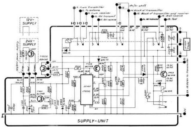
SUPPLY-UNIT
The Supply-Unit comprises the following circuits.
13,2V regulator
With 24V supplied from mains of the ship the 13,2V regulator consists of the transistors T1001 and T401.
The transistor T1001 is placed on the heatsink at the back of the set. The heatsink with T1001 mounted is named 24V supply-unit N203.
The zenerdiode D401 forms a reference voltage of 9.1V for the regulator.
10V regulator
The 10V regulator uses the integrated regulator IC401 and with the series transistors T1002, the regulator is able to supply the necessary current.
In case of short-circuiting 10V the transistor T402 and diode D404 together with T1002 and R406 protect by limiting the current to about 1 amp.
5V regulator
The 5V regulator is a fixed integrated voltage regulator, and supplied from the above-mentioned 13.2V regulator.
Blocking of Tx and Tx/Rx
The integrated voltage regulator IC401 has the feature that with ground on pin 13, no 10V will be supplied. This is used to block the transmitter as well as the receiver. With ground on pin 3 of IC401 and 0.7V supplied at the same time to pin 2 of IC401, no 10V will be supplied. With pin 3 of IC401 still grounded and 0V to pin 2 of IC401, 10V will be supplied. This is used to block the transmitter, but not the receiver.
Relay
On the Supply-Unit the transmit/receive relay RE401 and the 1W reduced power relay RE402 are placed.
With transmitter keyed the relay RE401 will operate. The relay RE402 will also operate if base of transistor T403 is not grounded from IW-Red, control wire. The current to Tx-Power-Amplifier will now pass through relay RE402.
With transmitter keyed and ground from IW-Red. control wire to base of T403, only the relay RE401 will operate and the current to TX-POWER-AMPLIFIER will pass through relay RE401 and drop resistor R420.

●: Connections to module.
TP: Testpoint.
Testconditions:
Voltages without brackets:
Operating in Rx-position (24 V supply).
Voltages in brackets:
Operating in Tx-position (24 V supply; full-power).
OSCILLATOR-UNIT
The Oscillator-Unit comprises the following circuits.
Oscillator
The transistor T501 is oscillating by means of a 11,1 MHz crystal. From the emitter of T501, 11,1 MHz - injection signal for second mixer is taken.
From the collector of T501, 11,1 MHz signal is fed via L501 to reference-driver.
Signal for the multiplier is also taken from the collector of T501 and by means of the double tuned filter comprising the components L502, L503, C513, C514 and C515, only third overtone is by-passed to the transistor T502.
Multiplier
The transistor T502 is multiplying with four and the bandpass filter comprising the components L504,
C518 and C519 is adjusted to 12x11,1 MHz.
Mixer and amplifier
The feed-back signal from the V.C.O. is amplified in the transistor T505 and fed via capacitor C527 to the mixer transistor T504. The mixer product is led to amplifier T503 via filter comprising the components L506, C523 and C526. From amplifier T504 the variable frequency signal is taken to the pro-driver in DIVIDER-UNIT.
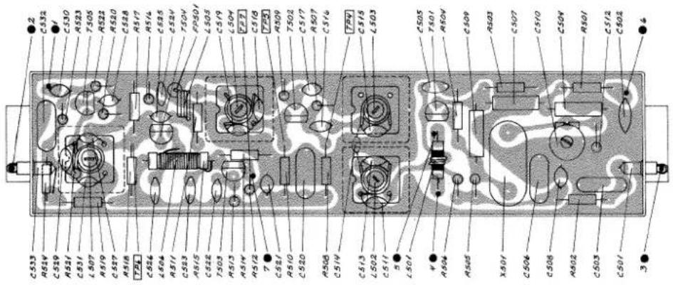
AC voltages outside frame of diagram.
▲: Measured with AF-voltmeter.
: Measured with testprobe
●: Connections to module.
TP: Testpoint.
Testconditions:
Voltages without brackets:
X-tal with typical activity.
Voltages in brackets:
X-tal with minimum activity.

DIVIDER-UNIT
The Divider-Unit comprises the following circuits.
Programmable divider
The variable frequency feed-back signal (11 MHz - 30 MHz) from the OSCILLATOR-UNIT is amplified in transistors T604, T605 and T606 to TTL-level. The programmable divider is dividing the variable frequency by the dividing-figure N and the working principle is the following.
The 145 potential frequencies in each band are controlled from the PROGRAMMING DISC, which encodes a start-figure P in the binary counters IC605 and IC608 from the switches S301, S302, S303, S304, S305, S306, S307 and S308. In the programmable divider it is possible to encode four different stop-figures S for each band, simplex/duplex-receive and normal/special-transmit and these bands are controlled from S310, S314 and 10V-Rx. The gates IC601a, IC602b, IC602c, IC609a, IC607b, IC609h, IC610a and IC601b are decoding the stop-figure S, and when outputs from the counters reach the chosen stop-figure S the J-K flip-flop IC606b will load the counters IC605 and IC608 with the start-figure P. The counting will now start again from the start-figure P. The dividing-figure is now N = S - P.
Reference-divider
The fixed frequency signal 11,1 MHz from the OSCILLATOR-UNIT is amplified in the transistors T603 to TTL-level.
The reference-divider is dividing the reference-frequency by the dividing figure N = 444 to 25 kHz and working principle is the following. The reference signal is first divided by 2 in the J-K flip-flop IC 606a.
The two binary counters IC603 and IC604 have the possibility of counting to 256.
The gates IC607a and IC602a will decode the outputs from the counters IC603 and IC604 and when the counters reach 222 the gates will reset the counters and they will start counting again.
Phase/frequency-detector
The fixed frequency signal 25 kHz and the variable frequency signal are passed to the phase/frequency-detector IC612. Proportional to frequency or phase difference between the two signals the phase/frequency-detector IC612 will generate an error voltage, which is passed to the loop-filter in TX-EXCITER-UNIT.
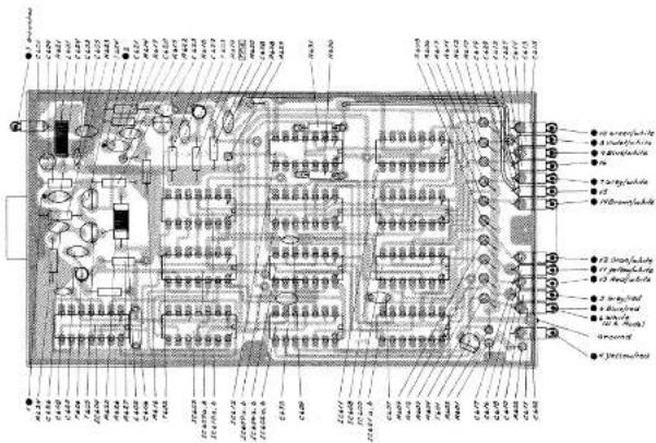
AC voltages outside frame of diagram.
©: Measured with testprobe
●: Connections to module.
TP: Testpoint.
Testconditions:
Voltages without brackets:
Operating in Rx-position.
Voltages in brackets:
Operating in Tx-position.
Measurements on connection points
5 to 14:
Connections ● 5 to ● 14 is programmed from the programming disc. The code to the connection points is described in the section Programming of Private Channels. A screw inserted gives a logical *0* (0V).
No screw gives a logical >1< (5V).

flowchart
graph TD
    A["Input Signal"] --> B["Diode 1"]
    A --> C["Diode 2"]
    A --> D["Diode 3"]
    A --> E["Diode 4"]
    B --> F["Control Signals"]
    C --> G["Control Signals"]
    D --> H["Control Signals"]
    E --> I["Control Signals"]
    F --> J["Output 1"]
    G --> K["Output 2"]
    H --> L["Output 3"]
    I --> M["Output 4"]
    J --> N["Output 5"]
    K --> O["Output 6"]
    L --> P["Output 7"]
    M --> Q["Output 8"]
    N --> R["Output 9"]
    O --> S["Output 10"]
    P --> T["Output 11"]
    Q --> U["Output 12"]
    R --> V["Output 13"]
    S --> W["Output 14"]
    T --> X["Output 15"]
    U --> Y["Output 16"]
    V --> Z["Output 17"]
    W --> AA["Output 18"]
    X --> AB["Output 19"]
    Y --> AC["Output 20"]
    Z --> AD["Output 21"]
    AA --> AE["Output 22"]
    AB --> AF["Output 23"]
    AC --> AG["Output 24"]
    AD --> AH["Output 25"]
    AE --> AI["Output 26"]
    AF --> AJ["Output 27"]
    AG --> AK["Output 28"]
    AH --> AL["Output 29"]
    AI --> AM["Output 30"]
    AJ --> AN["Output 31"]
    AK --> AO["Output 32"]
    AL --> AP["Output 33"]
    AM --> AQ["Output 34"]
    AN --> AR["Output 35"]
    AO --> AS["Output 36"]
    AP --> AT["Output 37"]
    AQ --> AU["Output 38"]
    AR --> AV["Output 39"]
    AS --> AW["Output 40"]
    AT --> AX["Output 41"]
    AU --> AY["Output 42"]
    AV --> AZ["Output 43"]
    AW --> BA["Output 44"]
HARMONIC FILTER
The transistors in the TX-POWER-AMPLIFIER are working in class C and will result in heavy distortion of the signal and therefore, in order to prevent disturbances on other services, it will be necessary to reduce the harmonic frequencies. For this purpose a filter is inserted between the TX-POWER-AMPLIFIER and the aerial. The harmonic filter consists of 3 M derived T-sections.


●: Connections to module.
TX-POWER-AMPLIFIER
The TX-POWER-AMPLIFIER is built up on a double-sided print board in stripline. The three transistors T801, T802 and T803 are all working as class C amplifiers. The 220 mW supplied to the transistor T801 are amplified to about 2,5W. The transistor T902 will amplify this to about 9W and the output transistor T803 will deliver an output of about 25W, this output being fed through C822 and C823 to the HARMONIC FILTER.
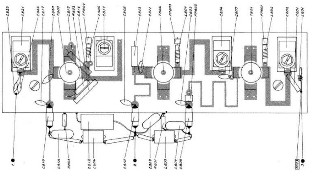

: Measured with testprobe
●: Connections to module.
TP: Testpoint.
Testconditions:
Voltages and current without brac- kets:
Tx-full-power.
Voltages and current in brackets:
Tx-reduced-power.
TX-EXCITER-UNIT
The Tx-Exciter-Unit comprises the following circuits.
Loop-filter
The operational amplifier IC901d in the loop-filter is summarizing the error voltage from the phase/frequency-detector in the following way.
If the phase-locked loop is locked, the voltage on both input terminals of IC901d pin 2 and pin 3 will be 1.5V and the voltage on the output terminal pin 1 will have a value between 2V and 10V corresponding to the V.C.O.-frequency. If the V.C.O.-frequency is too high, the error voltage from phase/frequency-detector IC612 will result in a current flowing from IC612 pin 10. This current will charge capacitor C919, so that the voltage on output terminal of IC901c pin 1 will decrease until the V.C.O.-frequency reaches the right value. (For principal understanding accept that C918 and R935 have no influence on the current, and also that no current is flowing into pin 2 of IC901d).
If the V.C.O.-frequency is too low an error voltage will result in a current flowing into pin 5 of IC612, and the voltage on pin 1 of IC901d will increase until the V.C.O.-frequency has reached the right value. The low-pass filter comprising the components L901, C920, C921 and C922, will attenuate the unwanted component on adjacent channels.
V.C.O.
The V.C.O. is a voltage controlled oscillator where the control voltage from the loop-filter can determine the frequency of the oscillator.
The field effect transistor T904 is the oscillator transistor, oscillating at a frequency mainly determined by the components L903, C929 and the variable capacitance diode D907.
Field effect transistor T905 is a buffer transistor.
From transmit to receive position the V.C.O.-frequency is shifting abruptly 10.7 MHz. In receive position, 10V from Rx/Tx-shift will open the diode D906 and the capacitor C927 is coupled parallel to the main determine frequency component of the V.C.O. In transmit position, 0V from Rx/Tx-shift is reversing the diode D906 and the capacitor C927 has no influence on the frequency of the V.C.O. In transmit position the reversed diode D906 is used as a variocap. diode for modulating the V.C.O.
Buffer- and driver-amplifier
From the V.C.O. the signal is passed to the parallel coupled buffer transistors T906, T907 and T908. The transistor T906 works as buffer for phase-locked loop feedback signal to OSCILLATOR-UNIT. The transistor T907 works as buffer for injection signal to the first mixer in RX-AMPLIFIER-UNIT. The transistors T908, T909 and
T910 work as buffer and amplifier for the transmitter signal.
The transistor T910 is the driver for the TX-POWER-AMPLIFIER. The potentiometer R963 can regulate the power output from driver transistor T910 from about 200 mW to 300 mW in 50 Ohm.
Microphone amplifier
The microphone signal from pre-amplifier A1001 is differentiated via capacitor C903 and the parallel combination of resistors R902 and and R903.
Transistor T901 works as amplifier. The microphone sensitivity can be adjusted by potentiometer R906.
Microphone compressor
The compressor is a circuit which will work as a normal amplifier for small input signals and keep a certain output level when the signal level has passed the threshold value. In fact the compressor is very much like an ordinary clipper circuit. One important difference is that the compressor will not make any distortion when a constant high input level is applied.
The signal from microphone amplifier is passed to the variable attenuator R911 and field effect transistor T902. In this configuration T902 works as a variable resistor. Variation of the DC-voltage on the gate of T902 will change the drain-source resistance of T902.
From the attenuator the signal is amplified in the operational amplifier IC901a, and inserted in the operational amplifier IC901b with gain -1. The two signals from IC901a and IC901b are now 180° out of phase. The full wave peak rectifier with diodes D903 and D904 will now start to rectify when the signal is higher than the threshold value. The transistor T903 will deliver current to charge the capacitor C911. The DC-voltage on C911 is now used to regulate the drain-source resistance of T902.
If the microphone signal has an amplitude higher than the threshold value, the DC-voltage on the capacitor C911 will regulate the resistance of T902 and attenuate the microphone signal to the level determined by the threshold value.
The potentiometer R909 adjusts the threshold value for the compressor. The diodes D901 and D902 are stabilizing the DC-working point for the operational amplifier.
Microphone low-pass filter
From the compressor the signal is fed to a low-pass filter which heavily attenuates all signals above 3 kHz. The low-pass filter is an active filter comprising the operational amplifier IC901c.
In transmit position the signal from the low-pass filter is passed to the modulation diode D906 in the V.C.O.
The potentiometer R931 is adjusted for maximum allowed frequency deviation.
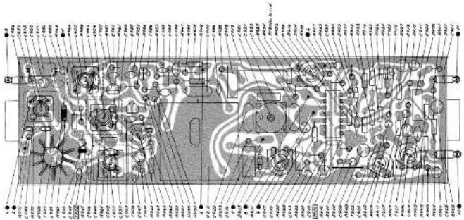
AC voltages outside frame of diagram.
▲: Measured with AF-voltmeter,
- Measured with testprobe
●: Connections to module.
TP: Testpoint.
Testconditions:
Voltages without brackets:
Operating in Rx-position,
Squelch closed.
Voltages in brackets:
Operating in Tx-position.
Modulation of transmitter: f = ± 3 kHz; fm = 1 kHz.
R906 adjusted to normal sensitivity.
AF-generator connected to micro-phone pre-amp. in the hook.

MICROPHONE PRE-AMPLIFIER
The Microphone Pre-Amplifier is built into the microtelephone handset.
The amplifier has got an input impedance of 200 ohm, equal to the microphone impedance. The
amplifier consists of the transistor T1101, the current of which is supplied through the collector transistor R901 placed in the TX-EXCITER-UNIT.


AC voltages outside frame of diagram.
▲: Measured with AF-voltmeter.
●: Connections to module.
Testconditions:
Voltages without brackets:
Operating in Rx-position.
Antenna signal 1 mV EMF: f = ± 3 kHz; fm = 1 kHz.
Squelch max. closed.
Voltages in brackets:
Operating in Tx-position.
AF-generator connected to point ● 1 and ● 2.
V_AF = 0.9mV EMF.
PROGRAMMING OF PRIVATE CHANNELS
The programming of a SAILOR VHF RT144 is made by means of a programming disc as far as frequencies and special requirements in connection with transmitter and
receiver are concerned. A standard programming disc has all the international maritime channels permanently coded and is prepared for coding of 5 private channels.

polar_bar
| Tapped holes | Value | | :--- | :--- | | P1 | 157,425 | | P2 | 157,375 | | P3 | 157,275 | | P4 | 157,225 | | P5 | 157,175 | | P6 | 157,125 | | P7 | 157,075 | | P8 | 157,025 | | P9 | 156,975 | | P10 | 156,925 | | P11 | 156,875 | | P12 | 156,725 | | P13 | 156,675 | | P14 | 156,625 | | P15 | 156,575 | | P16 | 156,475 | | P17 | 156,425 | | P18 | 156,375 | | P19 | 156,325 | | P20 | 156,275 | | P21 | 156,225 | | P22 | 156,175 | | P23 | 156,125 | | P24 | 156,075 | | P25 | 157,000 | | P26 | 157,300 | | P27 | 157,350 | | P28 | 157,400 | | P29 | 157,450 | | P30 | 156,300 | | P31 | 156,250 | | P32 | 156,350 | | P33 | 156,400 | | P34 | 156,500 | | P35 | 156,600 | | P36 | 156,650 | | P37 | 156,700 | | P38 | 156,800 | | P39 | 156,850 | | P40 | 156,900 | | P41 | 156,950 | | P42 | 157,000 | | P43 | 157,050 | | P44 | 157,100 | | P45 | 157,150 | | P46 | 157,200 | | P47 | 157,250 | | P48 | 157,300 | | P49 | 157,350 | | P50 | 157,400 | | P51 | 157,450 | | P52 | 157,500 | | P53 | 157,600 | | P54 | 157,650 | | P55 | 157,700 | | P56 | 157,800 | | P57 | 157,900 | | P58 | 158,000 | | P59 | 158,800 | | P60 | 159,900 | | P61 | 160,075 | | P62 | 160,225 | | P63 | 160,375 | | P64 | 160,425 | | P65 | 160,475 | | P66 | 160,625 | | P67 | 160,675 | | P68 | 160,875 | | P69 | 161,025 | | P70 | 161,125 | | P71 | 161,275 | | P72 | 161,425 | | P73 | 161,475 | | P74 | 162,075 | | P75 | 162,225 | | P76 | 162,375 | | P77 | 163,025 | | P78 | 163,325 | | P79 | 163,475 | | P80 | 164,025 | | P81 | 164,325 | | P82 | 164,475 | | P83 | 164,625 | | P84 | 164,875 | | P85 | 164,925 | | P86 | 164,975 | | P87 | 164,999 | | P88 | 164,999 | | P89 | 164,999 | | P90 | 164,999 | | P91 | 164,999 | | P92 | 164,999 | | P93 | 164,999 | | P94 | 164,999 | | P95 | 164,999 | | P96 | 164,999 | | P97 | 164,999 | | P98 | 164,999 | | P99 | 164,999 | | QP00 (labeled as 'Q') = (labeled as 'Q') / (labeled as 'Q') / (labeled as 'Q') / (labeled as 'Q') / (labeled as 'Q') / (labeled as 'Q') / (labeled as 'Q') / (labeled as 'Q') / (labeled as 'Q') / (labeled as 'Q') / (labeled as 'Q') / (labeled as 'Q') / (labeled as 'Q') / (labeled on the left) / (labeled on the right) / (labeled on the left) / (labeled on the left) / (labeled on the left) / (labeled on the left) / (labeled on the left) / (labeled on the left) / (labeled on the left) / (labeled on the left) / (labeled on the left) / (labeled on the left) / (labeled on the left) / (labeled on the left) / (labeled on the left) / (Labeled on the left) / (Labeled on the left) / (Labeled on the left) / (Labeled on the left) / (Labeled on the left) / (Labeled on the left) / (Labeled on the left) / (Labeled on the left) / (Labeled on the left) / (Labeled on the left) / (Labeled on the left) / (Labeled on the left) / (Labeled on the right) / (Labeled on the left) / (Labeled on the left) / (Labeled on the left) / (Labeled on the left) / (Labeled on the left) / (Labeled on the left) / (Labeled on the left) / (Labeled on the left) / (Labeled on the left) / (Labeled on the left) / (Labeled on the left) / (Labeled on the left) / (R): Tapped holes; Tapped holes; Tapped holes; Tapped holes; Tapped holes; Tapped holes; Tapped holes; Tapped holes; Tapped holes; Tapped holes; Tapped holes; Tapped holes; Tapped holes; Tapped holes; Tapped holes; Tapped holes; Tapped holes; Tapped holes; Tapped holes; Tapped holes; Tapped holes; Tapped holes; Tapped holes; Tapped holes; Tapped holes; Tapped holes: Tapped holes; Tapped holes: Tapped holes; Tapped holes: Tapped holes; Tapped holes: Tapped holes; Tapped holes: Tapped holes; Tapped holes: Tapped holes; Tapped holes: Tapped holes; Tapped holes: Tapped holes; Tapped holes: Tapped holes; Tapped holes: Tapped holes; Tapped holes: Tapped holes; Tapped holes: Tapped holes; Tapped holes: Tapped holes: Tapped holes; Tapped holes: Tapped holes; Tapped holes: Tapped holes; Tapped holes: Tapped holes; Tapped holes: Tapped holes; Tapped holes: Tapped holes; Tapped holes: Tapped holes; Tapped holes: Tapped holes; Tapped holes: Tapped holes; Tapped holes: Tapped holes; Tapped holes: Tapped holes; Tapped holes: Tapped holes; Tapped holes :Tapped holes; Tapped holes :Tapped holes; Tapped holes :Tapped holes; Tapped holes :Tapped holes; Tapped holes :Tapped holes; Tapped holes :Tapped holes; Tapped holes :Tapped holes; Tapped holes :Tapped holes; Tapped holes :Tapped holes; Tapped holes :Tapped holes; Tapped holes :Tapped holes; Tapped holes :Tapped holes; Tapped holes :Tapped holes;Tapped holes :Tapped holes;Tapped holes :Tapped holes;Tapped holes :Tapped holes;Tapped holes :Tapped holes;Tapped holes :Tapped holes;Tapped holes :Tapped holes;Tapped holes :Tapped holes;Tapped holes :Tapped holes;Tapped holes :Tapped holes;Tapped holes :Tapped holes;Tapped holes :Tapped holes;Tapped holes :Tapped holes;Tapped holes :N/A The chart displays a single column of values representing the frequency of each hole in a circle. The values are explicitly labeled above each circle and are numerically listed above each circle. The numbers below each circle represent the specific value of each hole. The chart is arranged in a grid format with rows and columns labeled by their respective values. The legend indicates that circles represent dots and squares represent triangles.Standard programming disc with frequency indication.
- Tapped holes
- Contact points (logical »o«)
Procedure of programming:
- Dismount control knobs on the front panel.
- Remove front panel by unscrewing the four screws at the corners.
- Remove dial plate.
- The programming disc is now
ready for programming.
- The programming is carried out by inserting programming screws in accordance with the instructions given in the below paragraph »Programming Alternatives«.

radar
| Position | Method Description | Value | | :--- | :--- | :--- | | Pos. 14 | Block of Transmitter | ~128" | | Pos. 13 | Normal or Special Transmit | ~64" | | Pos. 12 | Reduction to 1 Watt | ~32" | | Pos. 11 | Block of Transmitter and Receiver | ~16" | | Pos. 10 | Simplex or Duplex programming | ~8" | | Pos. 9 | U.S. - mode programming. (A-channels) | ~128" | | Pos. 8 | Channel programming | ~128" | | Pos. 7 | Channel programming | ~64" | | Pos. 6 | Channel programming | ~32" | | Pos. 5 | Channel programming | ~16" | | Pos. 4 | Channel programming | ~8" | | Pos. 3 | Channel programming | ~4" | | Pos. 2 | Channel programming | ~2" | | Pos. 1 | Channel programming | ~1" |○ Tapped holes
- Contact points (logical »o«)
Section of the programming disc with Pos.-explanation.
Programming Alternatives:
Programming of frequencies (Pos. 1 - Pos. 8, Pos. 10 and Pos. 13)
The set is prepared for programming of 5 private channels in the frequency band 155,0 MHz - 158,6 MHz. The channels can be selected as simplex or semi-duplex channels respectively, which means that at semi-duplex operation 4,6 MHz above the transmitting frequency is received. On the private channel positions it will also be possible to code the transmitter in the frequency band 159,6 MHz - 163,2 MHz (SPECIAL - TRANSMIT). Reduced datas on the output of the transmitter are here to be expected.
In the frequency table on page 21 the frequencies wanted for transmitting respectively reception are found. Then the programming to be used in Pos. 1 - Pos. 8 and the programming of Pos. 10 and Pos. 13 are read and the programming screws are inserted in a private channel position.
NOTE! Remove the screw in Pos. 11 for every private channel which is taken into use.
Blocking of transmitter and receiver (Pos. 11)
One or more of the international maritime channels can be blocked in order to comply with national claims. In the channel positions, where blocking is wanted, a programming screw is to be inserted in Pos. 11.
NOTE! Channel 16 excepted.
Reduced output (Pos. 12)
On all international maritime channels and private channels an automatic reduction of the output to below 1 Watt is possible. In the channel positions, where reduction is wanted, a programming screw is to be inserted in Pos. 12.
Blocking of transmitter (Pos. 14)
Can be used in the countries, in which they have channels only used for reception, e. g. channels for weather reports. In the channel positions, in which blocking of the transmitter is wanted, a programming screw is to be inserted in Pos. 14.
Submitting of an external information (Pos. 9)
From one or more optional channel positions it will be possible to submit an external information. This information is a contact connection to negative battery pole, which can be used for activating of a relay or a transistor.
Example of use is a supplementary Watch Receiver, blocking of which is desired, when RT144 is set on certain channels.
A wire is mounted from the contact-panel Pos. 9 to pin 2 of the power-connector J1002.
In the channel positions, in which an information (connection to battery pole) is wanted, a programming screw is to be inserted in Pos. 9.
U.S.-mode programming (A-channels) (Pos. 9)
In U.S.A. and Canada more of the international maritime duplex-channels are used as simplex-channels. Therefore the set is prepared for individual coding of the duplex-channels needed.
The wire, which is mounted on the contact panel Pos. 10, is to be moved to Pos. 9 on the contact panel. In the channel positions, which are wanted to be duplex-channels, a programming screw is to be inserted in Pos. 9.
The channel positions without a screw in Pos. 9 are simplex-channels (international channels and A-channels).
| Insert a screw in the Pos number marked ΘNo screw in the Pos number without marking | RECEIVE | TRANSMIT | |||||||||
| Pos 8 | Pos 7 | Pos 6 | Pos 5 | Pos 4 | Pos 3 | Pos 2 | Pos 1 | No screw in Pos 10 | Insert a screw in Pos 10 | No screw in Pos 13 | Insert a screw in Pos 13 |
| 128 | 64 | 32 | 16 | 8 | 4 | 2 | 1 | Frequency MHz | Frequency MHz | Frequency MHz | Frequency MHz |
| ⊖ | ⊖ | ⊖ | 155,000 | 159,600 | 155,000 | 159,600 | |||||
| ⊖ | ⊖ | ⊖ | ⊖ | 155,025 | 159,625 | 155,025 | 159,625 | ||||
| ⊖ | ⊖ | ⊖ | 155,050 | 159,650 | 155,050 | 159,650 | |||||
| ⊖ | ⊖ | ⊖ | ⊖ | 155,075 | 159,675 | 155,075 | 159,675 | ||||
| ⊖ | ⊖ | ⊖ | ⊖ | 155,100 | 159,700 | 155,100 | 159,700 | ||||
| ⊖ | ⊖ | ⊖ | ⊖ | ⊖ | 155,125 | 159,725 | 155,125 | 159,725 | |||
| ⊖ | ⊖ | 155,150 | 159,750 | 155,150 | 159,750 | ||||||
| ⊖ | ⊖ | ⊖ | 155,175 | 159,775 | 155,175 | 159,775 | |||||
| ⊖ | ⊖ | ⊖ | 155,200 | 159,800 | 155,200 | 159,800 | |||||
| ⊖ | ⊖ | ⊖ | ⊖ | 155,225 | 159,825 | 155,225 | 159,825 | ||||
| ⊖ | ⊖ | ⊖ | 155,250 | 159,850 | 155,250 | 159,850 | |||||
| ⊖ | ⊖ | ⊖ | ⊖ | 155,275 | 159,875 | 155,275 | 159,875 | ||||
| ⊖ | ⊖ | ⊖ | ⊖ | 155,300 | 159,900 | 155,300 | 159,900 | ||||
| ⊖ | ⊖ | ⊖ | ⊖ | ⊖ | 155,325 | 159,925 | 155,325 | 159,925 | |||
| ⊖ | ⊖ | ⊖ | 155,350 | 159,950 | 155,350 | 159,950 | |||||
| ⊖ | ⊖ | ⊖ | ⊖ | 155,375 | 159,975 | 155,375 | 159,975 | ||||
| ⊖ | ⊖ | ⊖ | ⊖ | 155,400 | 160,000 | 155,400 | 160,000 | ||||
| ⊖ | ⊖ | ⊖ | ⊖ | ⊖ | 155,425 | 160,025 | 155,425 | 160,025 | |||
| ⊖ | ⊖ | ⊖ | ⊖ | 155,450 | 160,050 | 155,450 | 160,050 | ||||
| ⊖ | ⊖ | ⊖ | ⊖ | ⊖ | 155,475 | 160,075 | 155,475 | 160,075 | |||
| ⊖ | ⊖ | ⊖ | ⊖ | ⊖ | 155,500 | 160,100 | 155,500 | 160,100 | |||
| ⊖ | ⊖ | ⊖ | ⊖ | ⊖ | ⊖ | 155,525 | 160,125 | 155,525 | 160,125 | ||
| ⊖ | 155,550 | 160,150 | 155,550 | 160,150 | |||||||
| ⊖ | ⊖ | 155,575 | 160,175 | 155,575 | 160,175 | ||||||
| ⊖ | ⊖ | 155,600 | 160,200 | 155,600 | 160,200 | ||||||
| ⊖ | ⊖ | ⊖ | 155,625 | 160,225 | 155,625 | 160,225 | |||||
| ⊖ | ⊖ | 155,650 | 160,250 | 155,650 | 160,250 | ||||||
| ⊖ | ⊖ | ⊖ | 155,675 | 160,275 | 155,675 | 160,275 | |||||
| ⊖ | ⊖ | ⊖ | 155,700 | 160,300 | 155,700 | 160,300 | |||||
| ⊖ | ⊖ | ⊖ | ⊖ | 155,725 | 160,325 | 155,725 | 160,325 | ||||
| ⊖ | ⊖ | 155,750 | 160,350 | 155,750 | 160,350 | ||||||
| ⊖ | ⊖ | ⊖ | 155,775 | 160,375 | 155,775 | 160,375 | |||||
| ⊖ | ⊖ | ⊖ | 155,800 | 160,400 | 155,800 | 160,400 | |||||
| ⊖ | ⊖ | ⊖ | ⊖ | 155,825 | 160,425 | 155,825 | 160,425 | ||||
| ⊖ | ⊖ | ⊖ | 155,850 | 160,450 | 155,850 | 160,450 | |||||
| ⊖ | ⊖ | ⊖ | ⊖ | 155,875 | 160,475 | 155,875 | 160,475 | ||||
| ⊖ | ⊖ | ⊖ | ⊖ | 155,900 | 160,500 | 155,900 | 160,500 | ||||
| ⊖ | ⊖ | ⊖ | ⊖ | ⊖ | 155,925 | 160,525 | 155,925 | 160,525 | |||
| ⊖ | ⊖ | 155,950 | 160,550 | 155,950 | 160,550 | ||||||
| ⊖ | ⊖ | ⊖ | 155,975 | 160,575 | 155,975 | 160,575 | |||||
| ⊖ | ⊖ | ⊖ | 156,000 | 160,600 | 156,000 | 160,600 | |||||
| ⊖ | ⊖ | ⊖ | ⊖ | 156,025 | 160,625 | 156,025 | 160,625 | ||||
| ⊖ | ⊖ | ⊖ | 156,050 | 160,650 | 156,050 | 160,650 | |||||
| ⊖ | ⊖ | ⊖ | ⊖ | 156,075 | 160,675 | 156,075 | 160,675 | ||||
| ⊖ | ⊖ | ⊖ | ⊖ | 156,100 | 160,700 | 156,100 | 160,700 | ||||
| ⊖ | ⊖ | ⊖ | ⊖ | ⊖ | 156,125 | 160,725 | 156,125 | 160,725 | |||
| ⊖ | ⊖ | ⊖ | 156,150 | 160,750 | 156,150 | 160,750 | |||||
| ⊖ | ⊖ | ⊖ | ⊖ | 156,175 | 160,775 | 156,175 | 160,775 | ||||
| ⊖ | ⊖ | ⊖ | ⊖ | 156,200 | 160,800 | 156,200 | 160,800 | ||||
| ⊖ | ⊖ | ⊖ | ⊖ | ⊖ | 156,225 | 160,825 | 156,225 | 160,825 | |||
| ⊖ | ⊖ | ⊖ | ⊖ | 156,250 | 160,850 | 156,250 | 160,850 | ||||
| ⊖ | ⊖ | ⊖ | ⊖ | ⊖ | 156,275 | 160,875 | 156,275 | 160,875 | |||
| ⊖ | ⊖ | ⊖ | ⊖ | ⊖ | 156,300 | 160,900 | 156,300 | 160,900 | |||
| ⊖ | ⊖ | ⊖ | ⊖ | ⊖ | ⊖ | 156,325 | 160,925 | 156,325 | 160,925 | ||
| ⊖ | ⊖ | 156,350 | 160,950 | 156,350 | 160,950 | ||||||
| ⊖ | ⊖ | ⊖ | 156,375 | 160,975 | 156,375 | 160,975 | |||||
| ⊖ | ⊖ | ⊖ | 156,400 | 161,000 | 156,400 | 161,000 | |||||
| ⊖ | ⊖ | ⊖ | ⊖ | 156,425 | 161,025 | 156,425 | 161,025 | ||||
| ⊖ | ⊖ | ⊖ | 156,450 | 161,050 | 156,450 | 161,050 | |||||
| ⊖ | ⊖ | ⊖ | ⊖ | 156,475 | 161,075 | 156,475 | 161,075 | ||||
| ⊖ | ⊖ | ⊖ | ⊖ | 156,500 | 161,100 | 156,500 | 161,100 | ||||
| ⊖ | ⊖ | ⊖ | ⊖ | ⊖ | 156,525 | 161,125 | 156,525 | 161,125 | |||
| ⊖ | ⊖ | ⊖ | 156,550 | 161,150 | 156,550 | 161,150 | |||||
| ⊖ | ⊖ | ⊖ | ⊖ | 156,575 | 161,175 | 156,575 | 161,175 | ||||
| ⊖ | ⊖ | ⊖ | ⊖ | 156,600 | 161,200 | 156,600 | 161,200 | ||||
| ⊖ | ⊖ | ⊖ | ⊖ | ⊖ | 156,625 | 161,225 | 156,625 | 161,225 | |||
| ⊖ | ⊖ | ⊖ | ⊖ | 156,650 | 161,250 | 156,650 | 161,250 | ||||
| ⊖ | ⊖ | ⊖ | ⊖ | ⊖ | 156,675 | 161,275 | 156,675 | 161,275 | |||
| ⊖ | ⊖ | ⊖ | ⊖ | ⊖ | 156,700 | 161,300 | 156,700 | 161,300 | |||
| ⊖ | ⊖ | ⊖ | ⊖ | ⊖ | ⊖ | 156,725 | 161,325 | 156,725 | 161,325 | ||
| ⊖ | ⊖ | ⊖ | 156,750 | 161,350 | 156,750 | 161,350 | |||||
| ⊖ | ⊖ | ⊖ | ⊖ | 156,775 | 161,375 | 156,775 | 161,375 | ||||
| ⊖ | ⊖ | ⊖ | ⊖ | 156,800 | 161,400 | 156,800 | 161,400 | ||||
| ⊖ | ⊖ | ⊖ | ⊖ | ⊖ | 156,825 | 161,425 | 156,825 | 161,425 | |||
| ⊖ | ⊖ | ⊖ | ⊖ | 156,850 | 161,450 | 156,850 | 161,450 | ||||
| ⊖ | ⊖ | ⊖ | ⊖ | ⊖ | 156,875 | 161,475 | 156,875 | 161,475 | |||
| ⊖ | ⊖ | ⊖ | ⊖ | ⊖ | 156,900 | 161,500 | 156,900 | 161,500 | |||
| ⊖ | ⊖ | ⊖ | ⊖ | ⊖ | ⊖ | 156,925 | 161,525 | 156,925 | 161,525 | ||
| ⊖ | ⊖ | ⊖ | ⊖ | 156,950 | 161,550 | 156,950 | 161,550 | ||||
| ⊖ | ⊖ | ⊖ | ⊖ | ⊖ | 156,975 | 161,575 | 156,975 | 161,575 | |||
| ⊖ | ⊖ | ⊖ | ⊖ | ⊖ | 157,000 | 161,600 | 157,000 | 161,600 | |||
| ⊖ | ⊖ | ⊖ | ⊖ | ⊖ | ⊖ | 157,025 | 161,625 | 157,025 | 161,625 | ||
| ⊖ | ⊖ | ⊖ | ⊖ | ⊖ | 157,050 | 161,650 | 157,050 | 161,650 | |||
| ⊖ | ⊖ | ⊖ | ⊖ | ⊖ | ⊖ | 157,075 | 161,675 | 157,075 | 161,675 | ||
| ⊖ | ⊖ | ⊖ | ⊖ | ⊖ | ⊖ | 157,100 | 161,700 | 157,100 | 161,700 | ||
| ⊖ | ⊖ | ⊖ | ⊖ | ⊖ | ⊖ | ⊖ | 157,125 | 161,725 | 157,125 | 161,725 | |
| 157,150 | 161,750 | 157,150 | 161,750 | ||||||||
| Θ | 157,175 | 161,775 | 157,175 | 161,775 | |||||||
| Θ | 157,200 | 161,800 | 157,200 | 161,800 | |||||||
| Θ | Θ | 157,225 | 161,825 | 157,225 | 161,825 | ||||||
| Θ | 157,250 | 161,850 | 157,250 | 161,850 | |||||||
| Θ | Θ | 157,275 | 161,875 | 157,275 | 161,875 | ||||||
| Θ | Θ | 157,300 | 161,900 | 157,300 | 161,900 | ||||||
| Θ | Θ | Θ | 157,325 | 161,925 | 157,325 | 161,925 | |||||
| Θ | 157,350 | 161,950 | 157,350 | 161,950 | |||||||
| Θ | Θ | 157,375 | 161,975 | 157,375 | 161,975 | ||||||
| Θ | Θ | 157,400 | 162,000 | 157,400 | 162,000 | ||||||
| Θ | Θ | Θ | 157,425 | 162,025 | 157,425 | 162,025 | |||||
| Θ | Θ | 157,450 | 162,050 | 157,450 | 162,050 | ||||||
| Θ | Θ | Θ | 157,475 | 162,075 | 157,475 | 162,075 | |||||
| Θ | Θ | Θ | 157,500 | 162,100 | 157,500 | 162,100 | |||||
| Θ | Θ | Θ | Θ | 157,525 | 162,125 | 157,525 | 162,125 | ||||
| Θ | 157,550 | 162,150 | 157,550 | 162,150 | |||||||
| Θ | Θ | 157,575 | 162,175 | 157,575 | 162,175 | ||||||
| Θ | Θ | 157,600 | 162,200 | 157,600 | 162,200 | ||||||
| Θ | Θ | Θ | 157,625 | 162,225 | 157,625 | 162,225 | |||||
| Θ | Θ | 157,650 | 162,250 | 157,650 | 162,250 | ||||||
| Θ | Θ | Θ | 157,675 | 162,275 | 157,675 | 162,275 | |||||
| Θ | Θ | Θ | 157,700 | 162,300 | 157,700 | 162,300 | |||||
| Θ | Θ | Θ | Θ | 157,725 | 162,325 | 157,725 | 162,325 | ||||
| Θ | Θ | 157,750 | 162,350 | 157,750 | 162,350 | ||||||
| Θ | Θ | Θ | 157,775 | 162,375 | 157,775 | 162,375 | |||||
| Θ | Θ | Θ | 157,800 | 162,400 | 157,800 | 162,400 | |||||
| Θ | Θ | Θ | Θ | 157,825 | 162,425 | 157,825 | 162,425 | ||||
| Θ | Θ | Θ | 157,850 | 162,450 | 157,850 | 162,450 | |||||
| Θ | Θ | Θ | Θ | 157,875 | 162,475 | 157,875 | 162,475 | ||||
| Θ | Θ | Θ | Θ | 157,900 | 162,500 | 157,900 | 162,500 | ||||
| Θ | Θ | Θ | Θ | Θ | 157,925 | 162,525 | 157,925 | 162,525 | |||
| Θ | 157,950 | 162,550 | 157,950 | 162,550 | |||||||
| Θ | Θ | 157,975 | 162,575 | 157,975 | 162,575 | ||||||
| Θ | Θ | 158,000 | 162,600 | 158,000 | 162,600 | ||||||
| Θ | Θ | Θ | 158,025 | 162,625 | 158,025 | 162,625 | |||||
| Θ | Θ | 158,050 | 162,650 | 158,050 | 162,650 | ||||||
| Θ | Θ | Θ | 158,075 | 162,675 | 158,075 | 162,675 | |||||
| Θ | Θ | Θ | 158,100 | 162,700 | 158,100 | 162,700 | |||||
| Θ | Θ | Θ | Θ | 158,125 | 162,725 | 158,125 | 162,725 | ||||
| Θ | Θ | 158,150 | 162,750 | 158,150 | 162,750 | ||||||
| Θ | Θ | Θ | 158,175 | 162,775 | 158,175 | 162,775 | |||||
| Θ | Θ | Θ | 158,200 | 162,800 | 158,200 | 162,800 | |||||
| Insert a screw in the Pos number markedNo screw in the Pos number without marking | RECEIVE | TRANSMIT | |||||||||
| Pos 8 | Pos 7 | Pos 6 | Pos 5 | Pos 4 | Pos 3 | Pos 2 | Pos 1 | No screw in Pos 10 | Insert a screw in Pos 10 | No screw in Pos 13 | Insert a screw in Pos 13 |
| 128 | 64 | 32 | 16 | 8 | 4 | 2 | 1 | Frequency MHz | Frequency MHz | Frequency MHz | Frequency MHz |
| 158,225 | 162,825 | 158,225 | 162,825 | ||||||||
| 158,250 | 162,850 | 158,250 | 162,850 | ||||||||
| 158,275 | 162,875 | 158,275 | 162,875 | ||||||||
| 158,300 | 162,900 | 158,300 | 162,900 | ||||||||
| 158,325 | 162,925 | 158,325 | 162,925 | ||||||||
| 158,350 | 162,950 | 158,350 | 162,950 | ||||||||
| 158,375 | 162,975 | 158,375 | 162,975 | ||||||||
| 158,400 | 163,000 | 158,400 | 163,000 | ||||||||
| 158,425 | 163,025 | 158,425 | 163,025 | ||||||||
| 158,450 | 163,050 | 158,450 | 163,050 | ||||||||
| 158,475 | 163,075 | 158,475 | 163,075 | ||||||||
| 158,500 | 163,100 | 158,500 | 163,100 | ||||||||
| 158,525 | 163,125 | 158,525 | 163,125 | ||||||||
| 158,550 | 163,150 | 158,550 | 163,150 | ||||||||
| 158,575 | 163,175 | 158,575 | 163,175 | ||||||||
| 158,600 | 163,200 | 158,600 | 163,200 | ||||||||
Normal Installation with 1 Microtelephone
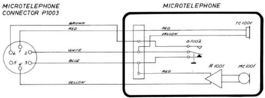
Special Installation with 2 Microtelephones
MICROTELEPHONE 1 WITH PREFERENCE

MECHANICAL LAYOUT

FRONT CHASSIS VIEW
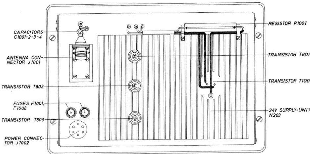
REAR CHASSIS VIEW


INNER CHASSIS VIEW

INNER CHASSIS VIEW


SERVICE
Maintenance
Preventive Maintenance
If SAILOR RT144 has been installed in a proper way, the maintenance can be reduced to an overhaul at each visit of the service staff.
Then inspect the set, the antenna, cables and plugs for mechanical damages, salt deposits, corrosion and any foreign bodies. Control the function of switches, volume control and of handset with holder.
Owing to its traditional structure the SAILOR RT144 has a long lifetime, but - always depending upon the circumstances, under which the set is working - it should be carefully controlled at intervals of no more than 12 month. The set must be taken to the service workshop to be tested. Along with each set a »Testsheet« is delivered, in which all the measurings made in the test department of the factory are listed. If the control measurings made in the service workshop should not show the same values as those listed in the »Testsheet«, the set must be adjusted like specified under Adjustment Procedure.
Alignment Instructions
Introduction
The measuring values indicated in the following paragraphs are typical values and are normative. Where exact values are indicated it will be necessary to use instruments in absolute conformity with the below list.
Necessary measuring instruments
VHF Signal Generator type TF2015 .... MARCONI
FM Modulation Meter type TF2303...... MARCONI
AF Voltmeter type IM21 HEATKIT
Distortion Analyser type IM58.... HEATHKIT
Tone Generator type PM5105.... PHILIPS
Electronic Multimeter type PM2503 ...... PHILIPS
RF Directional Wattmeter model 43 ...... BIRD
50W Load with 30 dB Attenuator type 8321 .. BIRD
Frequency counter
Frequency range: ≥ 175 MHz
Sensitivity: ≤ 100 mV
Impedance: ≥ 1 M Ohm and 50 Ohm
Accuracy: ≤ 1 · 10^-6
Test probe

Layout of the probe

ADJUSTMENT PROCEDURE
Adjustment of VOLTAGE REGULATORS
Alignment of 13,2V and 10V
Voltage Regulators
- Connect voltmeter to TP. 1.
- If it is a 24V station adjust R404 to 13,2V on the voltmeter.
- Connect voltmeter to TP. 2.
- Adjust potentiometer R412 to 10V ± 0.2V .
Adjustment of OSCILLATOR-UNIT
Alignment of Frequency
-
Connect frequency counter between TP. 3 and frame through luF.
-
Adjust trimmer capacitor C510, until the frequency counter shows 11100000 Hz ± 10 Hz.
Note: You can also count directly on the transmitting frequency, and fore adjustment of C510 you can use an arbitrary channel ex. ch. 16. f = 156800000 Hz ± 150 Hz.
Alignment of Multiplier and Mixer
-
Set CHANNEL SELECTOR on ch. 28.
-
Connect testprobe to TP. 4.
- Adjust coils L502 and L503 for maximum deflection on the Tp.-meter.
- Connect testprobe to TP. 5.
- Adjust coils L503 and L504 for maximum deflection on the Tp-meter.
- Connect the testprobe to TP. 6.
- Adjust coil L507 for maximum deflection on the Tp.-meter.
- Connect the testprobe to TP. 7.
- Fine adjustment of coils L502, L503 and L504.
Adjustment of RX- AMPLIFIER-UNIT and AUDIO-AMPLIFIER- UNIT
Alignment of RF- and
IF-Amplifier
-
Set CHANNEL SELECTOR on ch. 28.
-
Connect signal generator to antenna connector J1001.
-
Connect testprobe to TP. 8.
-
Set signal generator frequency to 162,000 MHz and increase signal level, until the deflection on the Tp.-meter reaches 30% of maximum deflection.
-
Readjust signal generator level under the following alignment always keeping the same deflection on the Tp.-meter.
-
Adjust coils L109 and L108 to maximum deflection on the Tp.-meter.
-
Repeat adjustment under point 6.
-
Adjust coils L107, L105, L106, L104, L103, L102 and L101 to maximum deflection on the Tp-meter.
-
Set CHANNEL SELECTOR on ch. 6.
-
Set signal generator frequency to 156,300 MHz.
-
Adjust coil L905 and L106 to maximum deflection on the Tp.-meter.
-
Adjust potentiometer R938 to maximum deflection on the Tp-meter.
-
Set CHANNEL SELECTOR on ch. 28.
-
Set signal generator frequency to 162,000 MHz.
-
Adjust coils L106, L104, L103, L102 and L101 to maximum deflection on the Tp.-meter.
-
Set CHANNEL SELECTOR on ch. 6.
-
Set signal generator frequency on 156,300 MHz.
-
Adjust potentiometer R938 and L106 to maximum deflection on the Tp.-meter.
Alignment of Detector, Telephone-Amplifier and LF-Power-Amplifier
-
Set CHANNEL SELECTOR on ch. 6.
-
Connect signal generator to antenna connector J1001.
-
Connect frequency counter between TP. 8 and frame through 10μF.
-
Set signal generator level to 1mV (no modulation).
-
Set signal generator frequency till frequency counter shows 400,0 kHz ± 0,1 kHz.
-
Connect voltmeter between TP. 9 and +10V.
-
Check that potentiometer R202 is in center position.
-
Rotate iron screw in coil L110 and take readings of Vmin. and Vmax. from the voltmeter (mean voltage).
-
Adjust coil L110 to (Vmin. + Vmax.) 12 on the voltmeter.
-
Connect AF-amplifier voltmeter to TP. 10.
-
Load TP. 10 with telephone or a 200 ohm resistor.
-
Set signal generator to modulation frequency 1000 Hz and deviation ± 3 kHz.
-
Adjust potentiometer R202 to 0,55 V (RMS) on AF-amplifier-voltmeter.
-
Connect distortion analyzer between TP. 11 and frame (IMPORTANT remember that there is 12V DC on TP. 11).
-
Set VOLUME control R1004 in max. position.
-
Adjust potentiometer R228 for an output, which gives 15% distortion.
-
Adjust volume control R1004 to 3,7V (RMS) over 4 ohm (3,5W).
-
Check that the distortion is less than 5%.
Alignment and Control of Receiver Sensitivity
-
Set CHANNEL SELECTOR on ch. 6.
-
Connect signal generator to antenna connector J1001.
-
Connect distortion analyzer between TP. 11 and frame (IMPORTANT remember that there is 12V DC on TP. 11).
-
Set signal generator to best sensitivity.
-
Adjustment L101 and L102 to best signal to noise ratio (best sensitivity).
-
Turn adjustment screw in L107 two turns C.W. and notice at the same time that the sensitivity is rising.
-
Check that the sensitivity on all channels is better than 0,6 uV EMK for 12 dB SINAD.
Alignment of Squelch
-
Set CHANNEL SELECTOR on ch. 6.
-
Connect signal generator to antenna connector J1001.
-
Turn Squelch potentiometer R1003 full C.W.
-
Set signal generator to best sensitivity and signal level 6 dB higher than the sensitivity point.
-
Adjust inside squelch potentiometer R206 till the squelch just starts to cut the noise.
Adjustment of TX- EXCITER-UNIT and TX- POWER-AMPLIFIER
Alignment of Output-Power
-
Set CHANNEL SELECTOR to ch. 14.
-
Set FUNCTION SWITCH in position 1W.
-
Connect RF-output power meter and a 50 ohm, 25W load resistor to antenna connector J1001.
-
Connect testprobe to TP. 12.
-
Turn potentiometer R963 fully C.C.W.
-
Key the transmitter.
-
Adjust coils L906, L907 and again L906 to maximum deflection on the Tp.-meter.
-
Connect testprobe to TP. 13.
-
Adjust coils L910, L907 to maximum deflection on the Tp-meter.
-
Set FUNCTION SWITCH in position ON.
-
Adjust capacitor C802, C806, C814 and C821 to maximum deflection on RF-output power meter.
-
Repeat adjustment under point 11.
1.3. Adjust potentiometer R963 to about 20W.
-
Connect testprobe to TP. 13.
-
Adjust coil L907 and L910 to maximum deflection on Tp-meter.
-
Adjust capacitors C802, C806, C814 and C821 to maximum deflection on RF-output power meter.
- Repeat adjustment: under point 16.
- Adjust potentiometer R963 to 20-25 W on RF-output power meter.
Alignment of reduced Transmitter Output
- Set FUNCTION SWITCH to position 1W.
- Connect RF-output power meter and a 50 ohm, 25W load resistor
to the antenna connector J1001. - Key the transmitter.
- Adjust resistor R419 until the RF-output power meter shows from 0.5W to 1W.
Alignment of Modulation
- Set CHANNEL SELECTOR on ch. 28.
- Connect tone generator, AF-voltmeter and Input Attenuator to MICROPHONE-PRE-AMPLIFIER input (Remove the microphone). See diagram.
-
Set FUNCTION SWITCH to position 1W,
-
Connect modulation meter loosely to the RF load resistor.
- Connect distortion analyzer to the modulation meter.
- Turn potentiometer R909 full C.W.
- Set tone generator to a frequency of 1000 Hz and the level to »Standard test signal«.
- Connect AF-voltmeter to TP.
- Key the transmitter.
- Adjust potentiometer R906 to 1.1 V RMS on testpoint TP. 14.
- Set tone generator to a frequency of 1000 Hz and the level to »Standard test signal +20 dB«.
- Connect AF-voltmeter to TP. 14.
- Adjust potentiometer R909 to 1.7 V RMS on testpoint TP. 14.
- Set tone generator level to »Standard test signal + 20 dB« and the frequency, which gives the largest + or - deviation abt. 3 kHz.
- Adjust potentiometer R931 for ± 5 kHz deviation.
- Set tone generator to a frequency of 1000 Hz and the level to *Standard test signal*.
- Fine adjust potentiometer R906 to ± 3 kHz deviation.
- Check that distortion is less than 5%.


Input Attenuator for MICROPHONE PRE-AMPLIFIER.

flowchart
graph LR
    A["Type Generator"] -->|I2| B["Antenna"]
    C["RF - Multimeter"] --> B
    B --> D["Microcontroller Phone"]
    D -->|am| E["Microcontroller Phone"]
    style A fill:#f9f,stroke:#333
    style C fill:#f9f,stroke:#333
    style B fill:#ccf,stroke:#333
    style D fill:#cfc,stroke:#333
*Standard test signal: Vg = 0.1V, (EMK = 2 mV).
*Standard test signal + 20 dB< Vp = 1V, (EMK = 20 mV).
NB: For check of transmitter audio frequency response connect LF-gene-
rator to MICROPHONE-CONNECTOR J1003.
Loadimpedance 200 ohm, level: EMK = 15 mV
TROUBLE-SHOOTING
Trouble-shooting should only be performed by persons with a sufficient technical knowledge, who have the necessary measuring instruments at their disposal, and who have carefully studied the operation principles and structure of SAILOR RT 144.
Commence by ascertaining, whether the fault is somewhere in the antenna circuit, the power source, the handset or in the transmitter - receiver unit.
For help with trouble-shooting in the SAILOR RT144 the section Circuit Description contains diagrams, principal descriptions and drawings showing the location of the individual components. In the diagrams typical values are indicated for the DC and AC voltages, just as the test points are indicated in both diagrams and location drawings.
SAILOR RT144 has a number of trimming cores and trimmers, which must not be touched, unless adjustments like specified under Adjustment Procedure can be made. When measuring in the units, shortcircuitings must be avoided as the transistors would then be spoiled.
Trouble-shooting in the frequency generating circuit
Below a couple of measuring methods to be made use of at the fault-finding in the frequency generating circuit will be described. Assumed is a thorough knowledge of the mode of operation of the frequency generating circuit, otherwise the sections Principle of Operation and Circuit Description should be carefully read.
At trouble-shooting the phase-locked loop can be opened, and if the system is o.k. it has the following mode of operation:
A counter capable of measuring frequencies in the 150 MHz range is connected to the coaxial cable supplying »LO-injection« to the RX-AMPLIFIER-UNIT.
The resistor lead to R937 is cut, and an external variable DC-control-voltage (1-10 V DC) is supplied to the resistor R937.
In position »receive« the »LO-injection« frequency will vary from abt. 140 MHz to abt. 154 MHz at a DC-control-voltage variation from 2V to 10V.
In position »transmit« the »LO-injection« frequency will vary from abt. 152 MHz to 166 MHz at a DC-control-voltage variation from 2V to 10V.
The input signals to pin 1 and pin 3 of MC4044 IC612 can be checked by means of an oscilloscope. The graphs are shown in section Circuit Description under DIVIDER-UNIT. If the DC-control-voltage to R937 is varied, it will be seen that signal on pin 3 of IC612 is varying in frequency above respectively below 25 kHz, and that the signal on pin 1 has a fixed frequency of 25 kHz.
The output voltage from MC4044 IC612 can be checked by means of a multi-meter on pin 5 and pin 10 respectively. If the DC-control-voltage is so adjusted that the frequency on pin 3 of IC612 is below 25 kHz, abt. 0,1V DC will be measured on pin 5 and abt. 0,1V DC on pin 10 of IC612 by means of a multi-meter. If the DC-control-voltage is so adjusted that the frequency on pin 3 of IC612 is above 25 kHz, abt. 2,3V DC on pin 10 and abt. 2,3V DC on pin 5 of IC612 will be measured by means of a multi-meter.
The output voltage on pin 1 of IC901d can be checked by means of a multi-meter. If the DC-control-voltage to R937 is varied, the DC-voltage measured on pin 1 of IC901d will change from 1V to 10V, when the frequency, for which the channel selector has been set, is surpassed.
Check on DIVIDER-UNIT coding:
The coding of DIVIDER-UNIT can be checked by means of the frequency table and description in section Programming of Private Channels.
One screw inserted into the programming disc will give a logical »0« (OV).
No screw in the programming disc will give a logical »1« (5V).
The 5V and 0V can be checked by means of a multi-meter on the terminals of the DIVIDER-UNIT. (The use of the terminals is described in the section Circuit Description under DIVIDER-UNIT).
Check on the phase-locked loop:
Check as to whether the phase-locked loop is locked (i. e. the V.C.O. generates the required frequency, for which the channel selector has been set). By means of a multi-meter the DC-control-voltage on the resistor lead to R937 is measured. If the DC-control-voltage is abt. 4-7V and changes its value from channel to channel, the phase-locked loop is locked.
If the DC-control-voltage is abt. IV or 10V, the phase-locked loop is not locked, and there is a fault in the system.
Symptoms of fault on the phase-locked loop:
When the set is incapable of transmitting and receiving in all channel positions! If all the DC-supply-voltages to the modules are o. k., the fault is to be found in the modules OSCILLATOR-UNIT, DIVIDER-UNIT or TX-EXCITER-UNIT.
When the frequency is incorrect in one or more of the channel positions, then the source of fault will be limited to the PROGRAMMING DISC or the DIVIDERUNIT.
Replacement of Modules
If a fault has been ascertained in a module, it may often, to save time, be worth-while to change it and then repair it later.
Replacement of Components
Changing of transistors, diodes, resistors, capacitors and similar components will involve the use of a small »pencil« soldering iron of 30 to 75 Watt rating. The soldering
must be performed rapidly to avoid overheating, and the use of a tin sucker is recommended, as otherwise there is the risk that both the components and the printed circuit will be spoiled.
Necessary Adjustment after replacement of Module
Replacement of RX-AMPLIFIER- UNIT:
Alignment of RF- and IF-Amplifier points 1 to 18.
Alignment of Detector, Telephone-Amplifier and LF-Power-Amplifier points 1 to 13.
Alignment and Control of Receiver Sensitivity points 1 to 7.
Alignment of Squelch points 1 to 5.
Replacement of AUDIO-AMPLIFIER-UNIT:
Alignment of Detector, Telephone-Amplifier and LF-Power-Amplifier points 10 to 18.
Alignment of Squelch points 1 to 5.
Replacement of SUPPLY-UNIT:
Alignment of 13,2 V and 10 V Voltage Regulators points 1 to 4.
Replacement of OSCILLATOR- UNIT:
Alignment of Frequency points 1 and 2.
Alignment of Multiplier and Mixer points 1 to 9.
Replacement of DIVIDER-UNIT: No alignments.
Replacement of TX-POWER-AMPLIFIER:
Alignment of Output-Power points 1 to 18.
Alignment of Reduced Transmitter Output points 1 to 4.
Replacement of TX-EXCITER- UNIT:
Alignment of Output-Power points 1 to 18.
Alignment of Modulation points 1 to 18.
Alignment of RF- and IF-Amplifier points 1 to 18.
Alignment and Control of Receiver Sensitivity points 1 to 7.
Replacement of V.C.O.:
Alignment of Modulation points 14 to 18.
Alignment of RF- and IF-Amplifier points 1 to 18.
Alignment and Control of Receiver Sensitivity points 1 to 7.
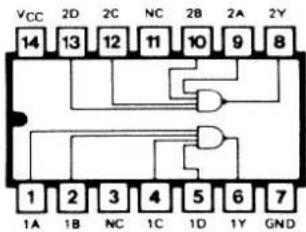
INTEGRATED CIRCUITS
SN7427N
Triple 3-input NOR gate

SN74H21N
Dual 4-input AND gate

SN7420N
Dual 4-input NAND gate
SN74197N
50 MHz Binary Counter
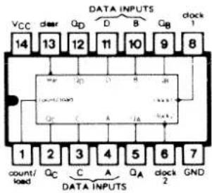
SN74S113N
Dual J-K master-slave flip-flop

SN7493N
4-bit binary counter
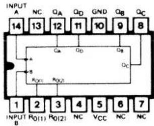

MC4044

Input Loading Factor: RI, VI = 3
Output Loading Factor (Pin 8) = 10
Total Power Dissipation = 85 mW typ/pkg
Propagation Delay Time = 9.0 ns typ (thru phase detector)
PHASE DETECTOR

flowchart
graph TD
    R1["1"] --> L1["L"]
    L1 --> AND1["&"]
    U1["13"] --> AND1
    U1 --> L2["L"]
    L2 --> AND2["&"]
    V1["3"] --> L3["L"]
    L3 --> AND3["&"]
    D1["2"] --> AND3
    D1 --> U2["12"]
    D1 --> U2
    D1 --> U2
    D1 --> U2
    D1 --> U2
    D1 --> U2
    D1 --> U2
    D1 --> U2
    D1 --> U2
    D1 --> U2
    D1 --> U2
    D1 --> U2
    D1 --> U2
    D1 --> U2
    D1 --> U2
    D1 --> U2
    U2 --> AND4["&"]
    U2 --> AND5["&"]
    U2 --> AND6["&"]
    U2 --> AND6
    U2 --> AND7["&"]
    U2 --> AND7
    U2 --> AND8["&"]
    U2 --> AND8
    U2 --> AND9["&"]
    U2 --> AND9
    U2 --> AND10["&"]
    U2 --> AND10
    U2 --> AND11["&"]
    U2 --> AND11
    U2 --> AND12["&"]
    U2 --> AND12
    U2 --> AND13["&"]
    U2 --> AND13
    U2 --> AND14["&"]
    U2 --> AND14
    U2 --> AND15["&"]
    U2 --> AND15
    U2 --> AND16["&"]
    U2 --> AND16
    U2 --> AND17["&"]
    U2 --> AND17
    U2 --> AND18["&"]
    U2 --> AND18
    U2 --> AND19["&"]
    U2 --> AND19
    U2 --> AND20["&"]
    U2 --> AND20
    U2 --> AND21["&"]
    U2 --> AND21
    U2 --> AND22["&"]
    U2 --> AND22
    U2 --> AND23["&"]
    U2 --> AND23
    U2 --> AND24["&"]
    U2 --> AND24
    U2 --> AND25["&"]
    U2 --> AND25
    U2 --> AND26["&"]
    U2 --> AND26
    U2 --> AND27["&"]
    U2 --> AND27
    U2 --> AND28["&"]
    U2 --> AND28
    U2 --> AND29["&"]
    U2 --> AND30["&"]
    U2 --> AND30
    U2 --> AND31["&"]
    U2 --> AND31
    U2 --> AND32["&"]
    U2 --> AND32
    U2 --> AND33["&"]
    U2 --> AND33
    U2 --> AND34["&"]
    U2 --> AND34
    U2 --> AND35["&"]
    U2 --> AND35
    U2 --> AND36["&"]
    U2 --> AND36
    U2 --> AND37["&"]
    U2 --> AND37
    U2 --> AND38["&"]
    U2 --> AND38
    U2 --> AND39["&"]
    U2 --> AND39
    U2 --> AND40["&"]
    U2 --> AND40
    U2 --> AND41["&"]
    U2 --> AND41
    U2 --> AND42["&"]
    U2 --> AND42
    U2 --> AND43["&"]
    U2 --> AND43
    U2 --> AND44["&"]
    U2 --> AND44
    U2 --> AND45["&"]
    U2 --> AND45
    U2 --> AND46["&"]
    U2 --> AND46
    U2 --> AND47["&"]
    U2 --> AND47
    U2 --> AND48["&"]
    U2 --> AND48
    U2 --> AND49["&"]
    U2 --> AND50["&"]
    U2 --> AND50
    U2 --> AND51["&"]
    U2 --> AND51
    U2 --> AND52["&"]
    U2 --> AND52
    U2 --> AND53["&"]
    U2 --> AND53
    U2 --> AND54["&"]
    U2 --> AND54
    U2 --> AND55["&"]
    U2 --> AND56["&"]
    U2 --> AND56
    U2 --> AND57["&"]
    U2 --> AND57
    U2 --> AND58["&"]
    U2 --> AND58
    U2 --> AND59["&"]
    U2 --> AND60["&"]
    U2 --> AND60
    U2 --> AND61["&"]
    U2 --> AND61
    U2 --> AND62["&"]
    U2 --> AND62
    U2 --> AND63["&"]
    U2 --> AND63
    U2 --> AND64["&"]
    U2 --> AND64
    U2 --> AND65["&"]
    U2 --> AND65
    U2 --> AND66["&"]
    U2 --> AND66
    U2 --> AND67["&"]
    U2 --> AND67
    U2 --> AND68["&"]
    U2 --> AND68
    U2 --> AND69["&"]
    U2 --> AND70["&"]
    U2 --> AND70
    U2 --> And71["&"]
    U2 --> And71
    U2 --> And71
    A["NOT"] --> B["AND Gate 1"]
    B --> C["U1 13"]
CHARGE PUMP

AMPLIFIER
1723C

PIN NUMBERS ADJACENT TO TERMINALS ARE FOR THE METAL AND CERAMIC FLAT PACKAGE. PIN NUMBERS IN PARENTHESIS ARE FOR THE CERAMIC QUAL IN-LINE PACKAGE.
TBA810AS

PIN. CONFIGURATION

RX-AMPLIFIER-UNIT RT144
| Symbol | Description | Manufact. | ||
| R101 | Resistor | 33 Kohm | Philips | 2322 101 33333 |
| R102 | Resistor | 33 Kohm | Philips | 2322 101 33333 |
| R103 | Resistor | 4,7 Kohm | Philips | 2322 101 33472 |
| R104 | Resistor | 10 Kohm | Philips | 2322 101 33103 |
| R105 | Resistor | 10 Kohm | Philips | 2322 101 33103 |
| R106 | Resistor | 180 ohm | Philips | 2322 101 33181 |
| R107 | Resistor | 1 Kohm | Philips | 2322 101 33102 |
| R108 | Resistor | 33 Kohm | Philips | 2322 101 33333 |
| R109 | Resistor | 33 Kohm | Philips | 2322 101 33333 |
| R110 | Resistor | 1,5 Kohm | Philips | 2322 101 33152 |
| R111 | Resistor | 330 ohm | Philips | 2322 101 33331 |
| R112 | Resistor | 33 Kohm | Philips | 2322 101 33333 |
| R113 | Resistor | 68 ohm | Philips | 2322 101 33689 |
| R114 | Resistor | 82 ohm | Philips | 2322 101 33829 |
| R115 | Resistor | 120 ohm | Philips | 2322 101 33121 |
| R116 | Resistor | 22 Kohm | Philips | 2322 106 33223 |
| R117 | Resistor | 47 Kohm | Philips | 2322 101 33473 |
| R118 | Resistor | 1 Kohm | Philips | 2322 101 33102 |
| R119 | Resistor | 1 Kohm | Philips | 2322 106 33102 |
| R120 | Resistor | 22 Kohm | Philips | 2322 101 33223 |
| R121 | Resistor | 220 ohm | Philips | 2322 101 33221 |
| R122 | Resistor | 1 Kohm | Philips | 2322 106 33102 |
| R123 | Resistor | 10 Kohm | Philips | 2322 106 33103 |
| R124 | Resistor | 22 Kohm | Philips | 2322 101 33223 |
| R125 | Resistor | 330 ohm | Philips | 2322 101 33332 |
| R126 | Resistor | 3,9 Kohm | Philips | 2322 101 33392 |
| C101 | Capacitor ceramic | 470pF/400V | Ferroperm | 9/0129,9 ± 20% |
| C102 | Capacitor ceramic | 22pF/400V | Ferroperm | 9/0116,9 ± 5% |
| C103 | Capacitor ceramic | 6,8pF/400V | Ferroperm | 9/0112,9 ± 0,25pF |
| C104 | Capacitor ceramic | 1nF/40V | Ferroperm | 9/0129,8 - 20 + 80 |
| C105 | Capacitor ceramic | 5,6pF/400V | Ferroperm | 9/0112,9 ± 0,25pF |
| C106 | Capacitor ceramic | 22pF/400V | Ferroperm | 9/0116,9 ± 5% |
| C107 | Capacitor ceramic | 470pF/40V | Ferroperm | 9/0129,8 - 20 + 80 |
| C108 | Capacitor ceramic | 470pF/40V | Ferroperm | 9/0129,8 - 20 + 80 |
| C109 | Capacitor ceramic | 470pF/40V | Ferroperm | 9/0129,8 - 20 + 80 |
RX-AMPLIFIER-UNIT RT144
| Symbol | Description | Manufact. | ||
| C110 | Capacitor ceramic | 22pF/400V | Ferroperm | 9/0116,9 ±5% |
| C111 | Capacitor ceramic | 6,8pF/400V | Ferroperm | 9/0112,9 ±0,25pF |
| C112 | Capacitor feed-through | 1nF/250V | Ferroperm | 9/0138,58 ÷20 +80 |
| C113 | Capacitor ceramic | 1nF/40V | Ferroperm | 9/0129,8 ÷20 +80 |
| C114 | Capacitor ceramic | 3,9pF/400V | Ferroperm | 9/0112,9 ±0,25pF |
| C115 | Capacitor ceramic | 22pF/400V | Ferroperm | 9/0116,9 ±5% |
| C116 | Capacitor ceramic | 4,7nF/30V | Ferroperm | 9/0145,9 ÷20 +80 |
| C117 | Capacitor ceramic | 1nF/40V | Ferroperm | 9/0129,8 ÷20 +80 |
| C118 | Capacitor ceramic | 4,7pF/400V | Ferroperm | 9/0112,9 ±10% |
| C119 | Capacitor ceramic | 5,6pF/400V | Ferroperm | 9/0112,9 ± 0,25pF |
| C120 | Capacitor ceramic | 27pF/ 400V | Ferroperm | 9/0119,9 ±10% |
| C121 | Capacitor ceramic | 120pF/63V | Ferroperm | 9/0121,8 ±10% |
| C122 | Capacitor ceramic | 22pF/400V | Ferroperm | 9/0116,9 ±5% |
| C123 | Capacitor polyester | 22nF/250V | Philips | 2222 342 44223 |
| C124 | Capacitor polyester | 22nF/250V | Philips | 2222 342 44223 |
| C125 | Capacitor ceramic | 10nF/30V | Ferroperm | 9/0145,9 ÷20 +80 |
| C126 | Capacitor ceramic | 47pF/400V | Ferroperm | 9/0121,9 ±10% |
| C127 | Capacitor tantal | 4,7uF/16V | ERO | ETP 2C |
| C128 | Capacitor ceramic | 5,6pF/400V | Ferroperm | 9/0112,9 ± 0,5pF |
| C129 | Capacitor tantal | 4,7uF/16V | ERO | ETP 2C |
| C130 | Capacitor polyester | 22nF/250V | Philips | 2222 342 44223 |
| C131 | Capacitor polystyrene | 100pF/500V | Philips | 2222 427 61001 |
| C132 | Capacitor polystyrene | 470pF/250V | Philips | 2222 426 24701 |
| C133 | Capacitor ceramic | 120pF/63V | Ferroperm | 9/0121,8 ±10% |
| C134 | Capacitor tantal | 4,7uF/16V | ERO | ETP 2C |
| C135 | Capacitor polystyrene | 3,9nF/63V | Philips | 2222 424 23902 |
| C136 | Capacitor tantal | 4,7uF/16V | ERO | ETP 2C |
| C137 | Capacitor polyester | 15nF/250V | Philips | 2222 342 45153 |
| C138 | Capacitor polystyrene | 180pF/500V | Philips | 2222 427 61801 |
| C139 | Capacitor polystyrene | 180pF/500V | Philips | 2222 427 61801 |
| C140 | Capacitor tantal | 4,7uF/16V | ERO | ETP 2C |
| C141 | Capacitor polystyrene | 4,7nF/63V | Philips | 2222 424 24702 |
| C142 | Capacitor feed-through | 1nF/250V | Ferroperm | 9/0138,58 ÷20 +80 |
| C143 | Capacitor feed-through | 1nF/250V | Ferroperm | 9/0138,58 ÷20 +80 |


RX-AMPLIFIER-UNIT RT144
| Symbol | Description | Manufact. | ||
| CP101 | ||||
| CP103 | Capacitor printed | S.P. | ||
| L101 | Coil | TL152 | S.P. | 6-0-20827 |
| L102 | Coil | TL153 | S.P. | 6-0-20828 |
| L103 | Coil | TL154 | S.P. | 6-0-20829 |
| L104 | Coil | TL155 | S.P. | 6-0-20830 |
| L105 | Coil | TL156 | S.P. | 6-0-20831 |
| L106 | Coil | TL157 | S.P. | 6-0-20832 |
| L107 | Coil | TL158 | S.P. | 6-0-20833 |
| L108 | Coil | TL159 | S.P. | 6-0-20834 |
| L109 | Coil | TL160 | S.P. | 6-0-20835 |
| L110 | Coil | TL161 | S.P. | 6-0-20836 |
| T101 | Transistor | Philips | BF200 | |
| T102 | Transistor | TEXAS | TIS88A | |
| T103 | Transistor | Philips | BF494 | |
| T104 | Transistor | Philips | BF199 | |
| D101 | Diode variocap. | group matched diodes | Motorola | MV109 M5 |
| D103 | Diode variocap. | Motorola | MV109 M5 | |
| D104 | Diode variocap. | Motorola | MV109 M5 | |
| D105 | Diode variocap. | Motorola | MV109 M5 | |
| D106 | Diode variocap. | Motorola | MV109 M5 | |
| D102 | Diode | Philips | BAW62 | |
| D107 | Diode | A.E.G. | AA138 | |
| D108 | Diode | Philips | BAX13 | |
RX-AMPLIFIER-UNIT RT144
| Symbol | Description | Manufact. | |
| IC101 | Integrated circuit | Siemens | TBA 120S |
| FP101 | Ferrit bead. Grade 4B | Philips | 4322 020 34420 |
| FL101 | Crystal filter 10,7 MHz | K.V.G. | XFM-107 B |
AUDIO-AMPLIFIER-UNIT RT144
| Symbol | Description | Manufact. | ||
| R201 | Resistor | 5,6 Kohm | Philips | 2322 101 33562 |
| R202 | Trimming potentiometer | 10 Kohm | Philips | 2322 410 03307 |
| R203 | Resistor | 82 Kohm | Philips | 2322 101 33823 |
| R204 | Resistor | 220 Kohm | Philips | 2322 101 33224 |
| R205 | Resistor | 180 Kohm | Philips | 2322 101 33184 |
| R206 | Trimming potentiometer | 2,2 Kohm | Philips | 2322 410 03305 |
| R207 | Resistor | 12 Kohm | Philips | 2322 101 33123 |
| R208 | Resistor | 39 Kohm | Philips | 2322 101 33393 |
| R209 | Resistor | 1,5 Kohm | Philips | 2322 101 33152 |
| R210 | Resistor | 18 Kohm | Philips | 2322 101 33183 |
| R211 | Resistor | 10 Kohm | Philips | 2322 101 33103 |
| R212 | Resistor | 15 Kohm | Philips | 2322 101 33153 |
| R213 | Resistor | 56 Kohm | Philips | 2322 101 33563 |
| R214 | Resistor | 100 Kohm | Philips | 2322 101 33104 |
| R215 | Resistor | 1 Kohm | Philips | 2322 101 33102 |
| R216 | Resistor | 1,8 Kohm | Philips | 2322 101 33182 |
| R217 | Resistor | 18 Kohm | Philips | 2322 101 33183 |
| R218 | Resistor | 3,9 Kohm | Philips | 2322 101 33392 |
| R219 | Resistor | 220 Kohm | Philips | 2322 101 33224 |
| R220 | Resistor | 5,6 Kohm | Philips | 2322 101 33562 |
| R221 | Resistor | 10 Kohm | Philips | 2322 101 33103 |
| R222 | Resistor | 100 Kohm | Philips | 2322 101 33104 |
| R223 | Resistor | 27 Kohm | Philips | 2322 101 33273 |
| R224 | Resistor | 4,7 Kohm | Philips | 2322 101 33472 |
| R225 | Resistor | 220 ohm | Philips | 2322 101 33221 |
| R226 | Resistor | 10 Kohm | Philips | 2322 101 33103 |
| R227 | Resistor | 22 Kohm | Philips | 2322 101 33223 |
| R228 | Trimming potentiometer | 4,7 Kohm | Philips | 2322 410 03306 |
| R229 | Resistor | 33 ohm | Philips | 2322 101 33339 |
| R230 | Resistor | 1 ohm | Philips | 2322 101 33108 |
| C201 | Capacitor polystyrene | 1nF/125V | Philips | 2222 425 21002 |
| C202 | Capacitor polystyrene | 1nF/125V | Philips | 2222 425 21002 |
| C203 | Capacitor polystyrene | 220pF/500V | Philips | 2222 427 22201 |
| C204 | Capacitor polyester | 22nF/250V | Philips | 2222 342 44223 |
| C205 | Capacitor polyester | 22nF/250V | Philips | 2222 342 44223 |
| C206 | Capacitor polyester | 0,22uF/100V | Philips | 2222 342 24224 |


AUDIO-AMPLIFIER-UNIT RT144
| Symbol | Description | Manufact. | ||
| C207 | Capacitor tantal | 0,47uF/35V | ERO | ETP 1A |
| C208 | Capacitor tantal | 1uF/35V | ERO | ETP 1A |
| C209 | Capacitor tantal | 1uF/35V | ERO | ETP 1A |
| C210 | Capacitor polyester | 22nF/250V | Philips | 2222 342 45223 |
| C211 | Capacitor polystyrene | 3,3nF/63V | Philips | 2222 424 23302 |
| C212 | Capacitor polyester | 0,22uF/100V | Philips | 2222 342 24224 |
| C213 | Capacitor polystyrene | 2,2nF/63V | Philips | 2222 424 22202 |
| C214 | Capacitor polyester | 0,22uF/100V | Philips | 2222 342 24224 |
| C215 | Capacitor polyester | 0,22uF/100V | Philips | 2222 342 24224 |
| C216 | Capacitor tantal | 4,7uF/16V | ERO | ETP 2C |
| C217 | Capacitor ceramic | 4,7nF/30V | Ferroperm | 9/0145,9 ÷20 +80 |
| C218 | Capacitor tantal | 33uF/10V | ERO | ETP 3G |
| C219 | Capacitor polyester | 0,1uF/100V | Philips | 2222 342 24104 |
| C220 | Capacitor electrolytic | 100uF/25V | Siemens | B41283-B5107-T |
| C221 | Capacitor electrolytic | 100uF/25V | Siemens | B41283-B5107-T |
| C222 | Capacitor electrolytic | 100uF/25V | Siemens | B41283-B5107-T |
| C223 | Capacitor polyester | 0,1uF/100V | Philips | 2222 342 24104 |
| C224 | Capacitor polyester | 10nF/250V | Philips | 2222 342 44103 |
| C225 | Capacitor ceramic | 1nF/40V | Ferroperm | 9/0129,8 ÷20 +80 |
| C226 | Capacitor polyester | 0,1uF/100V | Philips | 2222 342 24104 |
| C227 | Capacitor electrolytic | 470uF/16V | Siemens | B41283-A4477-T |
| T201 | Transistor | Philips | BC548 | |
| T202 | Transistor | Philips | BC558 | |
| T203 | Transistor | Philips | BC548 | |
| T204 | Transistor | Philips | BC548 | |
| T205 | Transistor | Philips | BC338-25 | |
| D201 | Diode | Philips | BAX13 | |
| D202 | Diode | Philips | BAX13 | |
| IC201 | Integrated circuit | Motorola | MC1458C | |
| IC202 | Integrated circuit | S.G.S. | TBA810AS | |


SUPPLY UNIT RT144
| Symbol | Description | Manufact. | ||
| R401 | Resistor | 1,5 Kohm | Philips | 2322 101 33152 |
| R402 | Resistor | 820 ohm | Philips | 2322 101 33821 |
| R403 | Resistor | 470 ohm | Philips | 2322 101 33471 |
| R404 | Trimming potentiometer | 470 ohm | Philips | 2322 410 03303 |
| R405 | Resistor | 220 ohm | Philips | 2322 101 33221 |
| R406 | Resistor | 1,2 ohm | Philips | 2322 212 13128 |
| R407 | Resistor | 100 ohm | Philips | 2322 101 33101 |
| R408 | Resistor | 2,2 Kohm | Philips | 2322 101 33222 |
| R409 | Resistor | 680 ohm | Philips | 2322 101 33681 |
| R410 | Resistor | 10 ohm | Philips | 2322 101 33109 |
| R411 | Resistor | 2,7 Kohm | Philips | 2322 101 33272 |
| R412 | Trimming potentiometer | 1 Kohm | Philips | 2322 410 03304 |
| R413 | Resistor | 2,2 Kohm | Philips | 2322 101 33222 |
| R414 | Resistor | 180 ohm | Philips | 2322 101 33181 |
| R415 | Resistor | 330 ohm | Philips | 2322 101 33331 |
| R416 | Resistor | 1 Kohm | Philips | 2322 101 33102 |
| R417 | Resistor | 3,3 Kohm | Philips | 2322 101 33332 |
| R418 | Resistor | 15 Kohm | Philips | 2322 101 33153 |
| R419 | Resistor | 4,7 Kohm | Philips | 2322 101 33472 |
| R420 | Resistor | 0-15 ohm 10W | Danotherm | GRV 10L 15 ohm |
| R421 | Resistor | 2,2 Kohm | Philips | 2322 101 33222 |
| C401 | Capacitor electrolytic | 2200uF/40V | Siemens | B41010-A7228-T |
| C402 | Capacitor polyester | 0,22uF/100V | Philips | 2222 342 24224 |
| C403 | Capacitor electrolytic | 100uF/25V | Siemens | B41283-B5107-T |
| C404 | Capacitor tantal | 33uF/10V | ERO | ETP-3G |
| C405 | Capacitor tantal | 33uF/10V | ERO | ETP-3G |
| C406 | Capacitor tantal | 22uF/16V | ERO | ETP-3G |
| C407 | Capacitor ceramic | 220pF/400V | Ferroperm | 9/0129,9 ± 20% |
| C408 | Capacitor ceramic | 220pF/400V | Ferroperm | 9/0129,9 ± 20% |
| C409 | Capacitor ceramic | 220pF/400V | Ferroperm | 9/0129,9 ± 20% |
| C410 | Capacitor tantal | 33uF/10V | ERO | ETP-3G |
| T401 | Transistor | Philips | BC548 | |
| T402 | Transistor | Philips | BC558 | |
SUPPLY UNIT RT144
| Symbol | Description | Manufact. | |
| T403 | Transistor | Philips | BC548 |
| D401 | Zenerdiode | Philips | BZX79 C9V1 |
| D402 | Zenerdiode | Silec | PL20Z |
| D403 | Diode | Philips | BAX13 |
| D404 | Diode | Philips | BAX13 |
| D405 | Diode | Philips | BAX13 |
| D406 | Diode | Philips | BAX13 |
| IC401 | Integrated circuit | Motorola | MC1723C |
| RE401 | Relay | A.E.G. | RHL454 86111-0-32 12V |
| RE402 | Relay | B.T.R. | 320 12V Spec. |
OSCILLATOR-UNIT RT144
| Symbol | Description | Manufact. | ||
| R501 | Resistor | 330 ohm | Philips | 2322 101 33331 |
| R502 | Resistor | 820 ohm | Philips | 2322 101 33821 |
| R503 | Resistor | 3,9 Kohm | Philips | 2322 101 33392 |
| R504 | Resistor | 33 Kohm | Philips | 2322 101 33333 |
| R505 | Resistor | 27 Kohm | Philips | 2322 106 33273 |
| R506 | Resistor | 390 ohm | Philips | 2322 106 33391 |
| R507 | Resistor | 10 Kohm | Philips | 2322 106 33103 |
| R508 | Resistor | 22 Kohm | Philips | 2322 101 33223 |
| R509 | Resistor | 10 Kohm | Philips | 2322 106 33103 |
| R510 | Resistor | 6,8 Kohm | Philips | 2322 101 33682 |
| R511 | Resistor | 1,5 Kohm | Philips | 2322 101 33152 |
| R512 | Resistor | 150 ohm | Philips | 2322 106 33151 |
| R513 | Resistor | 680 ohm | Philips | 2322 106 33681 |
| R514 | Resistor | 3,3 Kohm | Philips | 2322 101 33332 |
| R515 | Resistor | 270 ohm | Philips | 2322 212 13271 |
| R516 | Resistor | 560 ohm | Philips | 2322 106 33561 |
| R517 | Resistor | 4,7 Kohm | Philips | 2322 101 33472 |
| R518 | Resistor | 10 Kohm | Philips | 2322 101 33103 |
| R519 | Resistor | 270 ohm | Philips | 2322 101 33271 |
| R520 | Resistor | 330 ohm | Philips | 2322 106 33331 |
| R521 | Resistor | 560 ohm | Philips | 2322 106 33561 |
| R522 | Resistor | 1,8 Kohm | Philips | 2322 106 33182 |
| R523 | Resistor | 3,9 Kohm | Philips | 2322 106 33392 |
| R524 | Resistor | 270 ohm | Philips | 2322 101 33271 |
| C501 | Capacitor feed-through | 1nF/250V | Ferroperm | 9/0138,58 ÷20 +80 |
| C502 | Capacitor ceramic | 120pF/63V | Ferroperm | 9/0121,8 ± 10% |
| C503 | Capacitor polyester | 15nF/250V | Philips | 2222 342 44153 |
| C504 | Capacitor polystyrene | 1,2nF/63V | Philips | 2222 424 21202 |
| C505 | Capacitor ceramic | 22pF/400V | Ferroperm | 9/0116,9 ±10% |
| C506 | Capacitor polyester | 15nF/250V | Philips | 2222 342 44153 |
| C507 | Capacitor polystyrene | 82pF/500V | Philips | 2222 427 48209 |
| C508 | Capacitor ceramic | 470pF/40V | Ferroperm | 9/0129,8 ÷20 +80 |
| C509 | Capacitor polystyrene | 220pF/500V | Philips | 2222 427 42201 |
| C510 | Trimming capacitor | 1,5-9pF | D.A.U. | 107.1901.009 |
| C511 | Capacitor ceramic | 4,7nF/30V | Ferroperm | 9/0145,9 ÷20 +80 |
OSCILLATOR-UNIT RT144
| Symbol | Description | Manufact. | ||
| C512 | Capacitor polystyrene | 51pF/500V | Philips | 2222 427 85109 |
| C513 | Capacitor ceramic | 220pF/25V | Ferroperm | 9/0213,8 ±10% |
| C514 | Capacitor ceramic | 2,7pF/250V | Ferroperm | 9/0112,9 ±0,25pF |
| C515 | Capacitor ceramic | 220pF/25V | Ferroperm | 9/0213,8 ±10% |
| C516 | Capacitor ceramic | 4,7nF/30V | Ferroperm | 9/0145,9 ÷20 +80 |
| C517 | Capacitor ceramic | 1nF/40V | Ferroperm | 9/0129,8 ÷20 +80 |
| C518 | Capacitor ceramic | 33pF/63V | Ferroperm | 9/0116,8 ±10% |
| C519 | Capacitor ceramic | 33pF/63V | Ferroperm | 9/0116,8 ±10% |
| C520 | Capacitor polyester | 15nF/250V | Philips | 2222 342 44153 |
| C521 | Capacitor ceramic | 1nF/40V | Ferroperm | 9/0129,8 ÷20 +80 |
| C522 | Capacitor ceramic | 10nF/30V | Ferroperm | 9/0145,9 ÷20 +80 |
| C523 | Capacitor ceramic | 18pF/400V | Ferroperm | 9/0112,9 ±10% |
| C524 | Capacitor ceramic | 4,7nF/30V | Ferroperm | 9/0145,9 ÷20 +80 |
| C525 | Capacitor ceramic | 1nF/40V | Ferroperm | 9/0129,8 ÷20 +80 |
| C526 | Capacitor ceramic | 33pF/400V | Ferroperm | 9/0119,9 ±10% |
| C527 | Capacitor ceramic | 2,2pF/250V | Ferroperm | 9/0112,9 ±0,25pF |
| C528 | Capacitor ceramic | 470pF/40V | Ferroperm | 9/0129,8 ÷20 +80 |
| C529 | Capacitor ceramic | 5,6pF/400V | Ferroperm | 9/0112,9 ±0,5pF |
| C530 | Capacitor ceramic | 470pF/40V | Ferroperm | 9/0129,8 ÷20 +80 |
| C531 | Capacitor ceramic | 470pF/40V | Ferroperm | 9/0129,8 ÷20 +80 |
| C532 | Capacitor polyester | 15nF/250V | Philips | 2222 342 44153 |
| C533 | Capacitor feed-through | 1nF/250V | Ferroperm | 9/0138,58 ÷20 +80 |
| L501 | Coil | TL162 | S.P. | 6-0-20837 |
| L502 | Coil | TL163 | S.P. | 6-0-20838 |
| L503 | Coil | TL164 | S.P. | 6-0-20839 |
| L504 | Coil | TL165 | S.P. | 6-0-20840 |
| L505 | Coil | TL166 | S.P. | 6-0-20841 |
| L506 | Coil | TL167 | S.P. | 6-0-20842 |
| L507 | Coil | TL168 | S.P. | 6-0-20843 |
| FP501 | Ferrit bead. Grade 4B | Philips | 4322 020 34420 | |


OSCILLATOR-UNIT RT144
| Symbol | Description | Manufact. | |
| X501 | Crystal 11100.000 KHz | K.V.G. | |
| T501 | Transistor | Philips | BF199 |
| T502 | Transistor | Philips | BF199 |
| T503 | Transistor | Philips | BF450 |
| T504 | Transistor | Philips | BF199 |
| T505 | Transistor | Philips | BF199 |
DIVIDER-UNIT RT144
| Symbol | Description | Manufact. | ||
| R601 | Resistor | 10 Kohm | Philips | 2322 106 33103 |
| R602 | Resistor | 22 Kohm | Philips | 2322 106 33223 |
| R603 | Resistor | 5,6 Kohm | Philips | 2322 106 33562 |
| R604- | ||||
| R613 | Resistor | 33 Kohm | Philips | 2322 106 33333 |
| R614 | Resistor | 3,3 Kohm | Philips | 2322 101 33332 |
| R615 | Resistor | 390 ohm | Philips | 2322 106 33391 |
| R616 | Resistor | 4,7 Kohm | Philips | 2322 101 33472 |
| R617 | Resistor | 330 ohm | Philips | 2322 101 33331 |
| R618 | Resistor | 470 ohm | Philips | 2322 101 33471 |
| R619 | Resistor | 18 Kohm | Philips | 2322 101 33183 |
| R620 | Resistor | 1,5 Kohm | Philips | 2322 101 33152 |
| R621 | Resistor | 4,7 Kohm | Philips | 2322 101 33472 |
| R622 | Resistor | 4,7 Kohm | Philips | 2322 101 33472 |
| R623 | Resistor | 1 Kohm | Philips | 2322 101 33102 |
| R624 | Resistor | 100 ohm | Philips | 2322 101 33101 |
| R625 | Resistor | 150 ohm 12W | Philips | 2322 212 13151 |
| R626 | Resistor | 10 Kohm | Philips | 2322 101 33103 |
| R627 | Resistor | 470 ohm | Philips | 2322 101 33471 |
| R628 | Resistor | 10 Kohm | Philips | 2322 106 33103 |
| R629 | Resistor | 560 ohm | Philips | 2322 106 33561 |
| R630 | Resistor | 1 Kohm | Philips | 2322 101 33102 |
| R631 | Resistor | 1 Kohm | Philips | 2322 101 33102 |
| C601 | Capacitor feed-through | 1nF/250V | Ferroperm | 9/0138,58 ÷20 +80 |
| C602 | Capacitor feed-through | 1nF/250V | Ferroperm | 9/0138,58 ÷20 +80 |
| C603 | Capacitor ceramic | 10nF/30V | Ferroperm | 9/0145,9 ÷20 +80 |
| C604 | Capacitor tantal | 4,7uF/16V | ERO | ETP 2C |
| C605 | Capacitor ceramic | 470pF/40V | Ferroperm | 9/0129,8 ÷20 +80 |
| C606 | Capacitor polyester | 10nF/250V | Philips | 2222 342 44103 |
| C607 | Capacitor ceramic | 10nF/30V | Ferroperm | 9/0145,9 ÷20 +80 |
| C608 | Capacitor ceramic | 1nF/40V | Ferroperm | 9/0129,8 ÷20 +80 |
| C609 | Capacitor ceramic | 1nF/40V | Ferroperm | 9/0129,8 ÷20 +80 |
| C610- | ||||
| C619 | Capacitor feed-through | 1nF/250V | Ferroperm | 9/0138,58 ÷20 +80 |
DIVIDER-UNIT RT144
| Symbol | Description | Manufact. | ||
| C620- | ||||
| C623 | Capacitor ceramic | 10nF/30V | Ferroperm | 9/0145,9÷20+80 |
| C624- | ||||
| C626 | Capacitor ceramic | 4,7nF/30V | Ferroperm | 9/0145,9÷20+80 |
| C627 | Capacitor feed-through | 27pF/250V | Ferroperm | 9/0112,54±20% |
| C628 | Capacitor ceramic | 10nF/30V | Ferroperm | 9/0145,9÷20+80 |
| C629 | Capacitor feed-through | 1nF/250V | Ferroperm | 9/0138,58÷20+80 |
| C630 | Capacitor ceramic | 220pF/400V | Ferroperm | 9/0129,9±20% |
| L601 | Coil | TL169 | S.P. | 6-0-20844 |
| L602 | Coil | TL170 | S.P. | 6-0-20845 |
| T601 | Transistor | Philips | BC548 | |
| T602 | Transistor | Philips | BF199 | |
| T603 | Transistor | Philips | 2N2368 | |
| T604 | Transistor | Philips | BF199 | |
| T605 | Transistor | Philips | BF199 | |
| T606 | Transistor | Philips | 2N2368 | |
| IC601 | Integrated circuit | TEXAS | SN74H21 | |
| IC602 | Integrated circuit | TEXAS | SN7427 | |
| IC603 | Integrated circuit | TEXAS | SN7493A | |
| IC604 | Integrated circuit | TEXAS | SN7493A | |
| IC605 | Integrated circuit | TEXAS | SN74197 | |
| IC606 | Integrated circuit | TEXAS | SN74S113 | |
| IC607 | Integrated circuit | TEXAS | SN7420 | |
| IC608 | Integrated circuit | TEXAS | SN74197 | |
| IC609 | Integrated circuit | TEXAS | SN7420 | |
| IC610 | Integrated circuit | TEXAS | SN74H20 | |
| IC611 | Integrated circuit | TEXAS | SN74197 | |
| IC612 | Integrated circuit | Motorola | MC4044 | |
HARMONIC FILTER RT144
| Symbol | Description | Manufact. | ||
| C701 | Capacitor ceramic | 7,5 pF/400V | Ferroperm | 9/0112,9 ±5% |
| C702- | ||||
| C704 | Capacitor feed-through | 27 pF | Ferroperm | 9/0112,5 ±5% |
| C705 | Capacitor ceramic | 7,5 pF/400V | Ferroperm | 9/0112,9 ±5% |
TX-POWER-AMPLIFIER RT144
| Symbol | Description | Manufact. | ||
| R801 | Resistor | 10 ohm | Philips | 2322 101 33109 |
| R802 | Resistor | 22 ohm 12W | Philips | 2322 212 13229 |
| R803 | Resistor | 10 ohm | Philips | 2322 101 33109 |
| C801 | Capacitor ceramic | 47pF/250V | Ferroperm | 9/0116,3 ±10% |
| C802 | Trimming capacitor | 10-80pF | Radioparts | S14 |
| C803 | Capacitor ceramic | 1nF/40V | Ferroperm | 9/0129,8 ÷20 +80 |
| C804 | Capacitor polyester | 0,1uF/100V | Philips | 2222 342 24104 |
| C805 | VHF- -Filter | Ferroperm | 9/0168,5 | |
| C806 | Trimming capacitor | 10-80pF | Radioparts | S14 |
| C807 | Capacitor ceramic | 22pF/400V | Ferroperm | 9/0116,9 ±10% |
| C808 | Capacitor ceramic | 1nF/40V | Ferroperm | 9/0129,8 ÷20 +80 |
| C809 | Capacitor polyester | 0,1uF/100V | Philips | 2222 342 24104 |
| C810 | VHF- -Filter | Ferroperm | 9/0168,5 | |
| C811 | Capacitor ceramic | 15pF/400V | Ferroperm | 9/0112,9 ±10% |
| C812 | Capacitor electrolytic | 100uF/25V | Siemens | B41283-B5107-T |
| C813 | Capacitor ceramic | 33pF/400V | Ferroperm | 9/0116,3 ±10% |
| C814 | Trimming capacitor | 10-80pF | Radioparts | S14 |
| C815 | Capacitor ceramic | 68pF/250V | Ferroperm | 9/0116,3 ±10% |
| C816 | Capacitor ceramic | 68pF/250V | Ferroperm | 9/0116,3 ±10% |
| C817 | Capacitor ceramic | 1nF/40V | Ferroperm | 9/0129,8 ÷20 +80 |
| C818 | Capacitor polyester | 0,1uF/100V | Philips | 2222 342 24104 |
| C819 | VHF- -Filter | Ferroperm | 9/0168,5 | |
| C820 | Capacitor ceramic | 22pF/400V | Ferroperm | 9/0116,9 ±10% |
| C821 | Trimming capacitor | 10-80pF | Radioparts | S14 |
| C822 | Capacitor ceramic | 470pF/400V | Ferroperm | 9/0129,9 ± 20% |
| C823 | Capacitor ceramic | 470pF/400V | Ferroperm | 9/0129,9 ± 20% |
| L801 | Coil | TL066 | S.P. | 6-0-20846 |
| L802 | Coil | 0,15uHy | Jahre | 71,1 |
| L803 | Coil | TL067 | S.P. | 6-0-20854 |
| L804 | Coil | 0,15uHy | Ferroperm | 1587 |
| L805 | Coil | 0,15uHy | Ferroperm | 1587 |


TX-POWER-AMPLIFIER RT144
| Symbol | Description | Manufact. | ||
| L806 | Coil | TL067 | S.P. | 6-0-20854 |
| FP801 | Ferrit bead. | Grade 3B | Philips | 4322 020 34400 |
| FP802 | Ferrit bead. | Grade 3B | Philips | 4322 020 34400 |
| FP803 | Ferrit bead. | Grade 3B | Philips | 4322 020 34400 |
| FP804 | Ferrit bead. | Grade 3B | Philips | 4322 020 34400 |
| T801 | Transistor | Motorola | 2N5589 | |
| T802 | Transistor | Motorola | 2N5590 | |
| T803 | Transistor | Motorola | 2N5591 | |
TX-EXCITER-UNIT RT144
| Symbol | Description | Manufact. | ||
| R901 | Resistor | 4,7 Kohm | Philips | 2322 106 33472 |
| R902 | Resistor | 1,2 Kohm | Philips | 2322 101 33122 |
| R903 | Resistor | 3,3 Kohm | Philips | 2322 101 33332 |
| R904 | Resistor | 680 ohm | Philips | 2322 101 33681 |
| R905 | Resistor | 1 Kohm | Philips | 2322 106 33102 |
| R906 | Trimming potentiometer | 1 Kohm | Philips | 2322 410 03304 |
| R907 | Resistor | 4,7 Kohm | Philips | 2322 106 33472 |
| R908 | Resistor | 18 Kohm | Philips | 2322 106 33183 |
| R909 | Trimming potentiometer | 10 Kohm | Philips | 2322 410 03307 |
| R910 | Resistor | 56 Kohm | Philips | 2322 106 33563 |
| R911 | Resistor | 100 Kohm | Philips | 2322 101 33104 |
| R912 | Resistor | 1 Kohm | Philips | 2322 106 33102 |
| R913 | Resistor | 220 Kohm | Philips | 2322 101 33224 |
| R914 | Resistor | 100 Kohm | Philips | 2322 106 33104 |
| R915 | Resistor | 220 Kohm | Philips | 2322 106 33224 |
| R916 | Resistor | 180 ohm | Philips | 2322 101 33181 |
| R917 | Resistor | 3,3 Kohm | Philips | 2322 101 33332 |
| R918 | Resistor | 22 Kohm | Philips | 2322 101 33223 |
| R919 | Resistor | 4,7 Kohm | Philips | 2322 106 33472 |
| R920 | Resistor | 22 Kohm | Philips | 2322 106 33223 |
| R921 | Resistor | 3,3 Kohm | Philips | 2322 106 33332 |
| R922 | Resistor | 12 Kohm | Philips | 2322 101 33123 |
| R923 | Resistor | 22 Kohm | Philips | 2322 101 33223 |
| R924 | Resistor | 100 ohm | Philips | 2322 106 33101 |
| R925 | Resistor | 12 Kohm | Philips | 2322 106 33123 |
| R926 | Resistor | 220 Kohm | Philips | 2322 106 33224 |
| R927 | Resistor | 1,5 Kohm | Philips | 2322 106 33152 |
| R928 | Resistor | 10 Kohm | Philips | 2322 106 33103 |
| R929 | Resistor | 15 Kohm | Philips | 2322 101 33153 |
| R930 | Resistor | 22 Kohm | Philips | 2322 101 33223 |
| R931 | Trimming potentiometer | 4,7 Kohm | Philips | 2322 410 03306 |
| R932 | Resistor | 2,7 Kohm | Philips | 2322 106 33272 |
| R933 | Resistor | 270 ohm | Philips | 2322 106 33271 |
| R934 | Resistor | 1,5 Mohm | Philips | 2322 101 33155 |
| R935 | Resistor | 1 Kohm | Philips | 2322 106 33102 |
| R936 | Resistor | 1,2 Kohm | Philips | 2322 101 33122 |
| R937 | Resistor | 1,2 Kohm | Philips | 2322 106 33122 |
| R938 | Trimming potentiometer | 10 Kohm | Philips | 2322 410 03307 |
| R939 | Resistor | 10 Kohm | Philips | 2322 106 33103 |


TX-EXCITER-UNIT RT144
| Symbol | Description | Manufact. | ||
| R940 | Resistor | 1 Kohm | Philips | 2322 106 33102 |
| R941 | Resistor | 4,7 Kohm | Philips | 2322 106 33472 |
| R942 | Resistor | 10 ohm | Philips | 2322 101 33109 |
| R943 | Resistor | 560 ohm | Philips | 2322 106 33561 |
| R944 | Resistor | 680 ohm | Philips | 2322 106 33681 |
| R945 | Resistor | 220 ohm | Philips | 2322 106 33221 |
| R946 | Resistor NTC | 1 Kohm | Philips | 2322 642 11102 |
| R947 | Resistor | 330 ohm | Philips | 2322 106 33331 |
| R948 | Resistor | 100 ohm | Philips | 2322 101 33101 |
| R949 | Resistor | 2,2 Kohm | Philips | 2322 106 33222 |
| R950 | Resistor | 3,9 Kohm | Philips | 2322 106 33392 |
| R951 | Resistor | 150 ohm | Philips | 2322 106 33151 |
| R952 | Resistor | 390 ohm | Philips | 2322 106 33391 |
| R953 | Resistor | 68 ohm | Philips | 2322 106 33689 |
| R954 | Resistor | 47 ohm | Philips | 2322 101 33479 |
| R955 | Resistor | 330 ohm | Philips | 2322 106 33331 |
| R956 | Resistor | 150 ohm | Philips | 2322 106 33151 |
| R957 | Resistor | 470 ohm | Philips | 2322 106 33471 |
| R958 | Resistor | 1 Kohm | Philips | 2322 106 33102 |
| R959 | Resistor | 100 ohm | Philips | 2322 106 33101 |
| R960 | Resistor | 390 ohm | Philips | 2322 106 33391 |
| R961 | Resistor | 1 Kohm | Philips | 2322 106 33102 |
| R962 | Resistor | 1,5 Kohm | Philips | 2322 101 33152 |
| R963 | Trimming potentiometer | 2,2 Kohm | Philips | 2322 410 03305 |
| R964 | Resistor | 8,2 Kohm | Philips | 2322 101 33822 |
| R965 | Resistor | 220 ohm | Philips | 2322 106 33220 |
| R966 | Resistor | 47 ohm | Philips | 2322 106 33479 |
| R967 | Resistor | 82 ohm | Philips | 2322 101 33829 |
| R968 | Resistor | 2,2 Kohm | Philips | 2322 101 33222 |
| R969 | Resistor | 10 Kohm | Philips | 2322 106 33103 |
| R970 | Resistor | 120 ohm | Philips | 2322 106 33121 |
| R971 | Resistor | 10 Kohm | Philips | 2322 101 33103 |
| C901 | Capacitor feed-through | 1nF/250V | Ferroperm | 9/0138,58 ÷20 +80 |
| C902 | Capacitor feed-through | 1nF/250V | Ferroperm | 9/0138,58 ÷20 +80 |
| C903 | Capacitor polyester | 33nF/250V | Philips | 2222 342 45333 |
| C904 | Capacitor ceramic | 4,7nF/30V | Ferroperm | 9/0145,9 -20 +80 |
| C905 | Capacitor tantal | 22uF/16V | ERO | ETP 3G |
TX-EXCITER-UNIT RT144
| Symbol | Description | Manufact. | ||
| C906 | Capacitor tantal | 10uF/16V | ERO | ETP 2E |
| C907 | Capacitor tantal | 0,47uF/35V | ERO | ETP 1A |
| C908 | Capacitor tantal | 22uF/16V | ERO | ETP 3G |
| C909 | Capacitor tantal | 0,1uF/35V | ERO | ETP 1A |
| C910 | Capacitor tantal | 1uF/16V | ERO | ETP 1A |
| C911 | Capacitor tantal | 4,7uF/16V | ERO | ETP 2C |
| C912 | Capacitor tantal | 22uF/16V | ERO | ETP 3G |
| C913 | Capacitor tantal | 0,47uF/35V | ERO | ETP 1A |
| C914 | Capacitor polystyrene | 910pF/125V | Philips | 2222 425 29101 |
| C915 | Capacitor polystyrene | 15nF/63V | Philips | 2222 424 61503 |
| C916 | Capacitor polyester | 0,22uF/100V | Philips | 2222 342 25224 |
| C917 | Capacitor tantal | 4,7uF/16V | ERO | ETP 2C |
| C918 | Capacitor polyester | 33nF/250V | Philips | 2222 342 45333 |
| C919 | Capacitor polyester | 1uF/100V | Philips | 2222 344 25105 |
| C920 | Capacitor polyester | 15nF/250V | Philips | 2222 342 45153 |
| C921 | Capacitor polystyrene | 680pF/125V | Philips | 2222 425 46801 |
| C922 | Capacitor polyester | 47nF/250V | Philips | 2222 342 45473 |
| C923 | Capacitor tantal | 0,47uF/35V | ERO | ETP 1A |
| C924 | Capacitor ceramic | 220pF/400V | Ferroperm | 9/0129,9 ± 20% |
| C925 | Capacitor tantal | 10uF/16V | ERO | ETP 2E |
| C926 | Capacitor ceramic | 220pF/400V | Ferroperm | 9/0129,9 ± 20% |
| C927 | Capacitor ceramic | 4,5pF/400V | Ferroperm | 9/0112,9 ± 0,1pF |
| C928 | Capacitor ceramic | 220pF/400V | Ferroperm | 9/0129,9 ± 20% |
| C929 | Capacitor ceramic | 18pF/400V | Ferroperm | 9/0112,9 ± 5% |
| C930 | Capacitor ceramic | 15pF/400V | Ferroperm | 9/0112,9 ± 5% |
| C931 | Capacitor ceramic | 6,8pF/400V | Ferroperm | 9/0116,9 ± 0,25% |
| C932 | Capacitor ceramic | 330pF/25V | Ferroperm | 9/0213,8 ± 10% |
| C933 | Capacitor ceramic | 220pF/400V | Ferroperm | 9/0129,9 ± 20% |
| C934 | Capacitor ceramic | 220pF/400V | Ferroperm | 9/0129,9 ± 20% |
| C935 | Capacitor ceramic | 470pF/40V | Ferroperm | 9/0129,8 -20 +80% |
| C936 | Capacitor ceramic | 1nF/40V | Ferroperm | 9/0129,8 -20 +80% |
| C937 | Capacitor ceramic | 470pF/40V | Ferroperm | 9/0129,8 -20 +80% |
| C938 | Capacitor ceramic | 220pF/400V | Ferroperm | 9/0129,9 ± 20% |
| C939 | Capacitor ceramic | 470pF/40V | Ferroperm | 9/0129,8 -20 +80% |
| C940 | Capacitor polyester | 15nF/250V | Philips | 2222 342 44153 |
| C941 | Capacitor ceramic | 470pF/40V | Ferroperm | 9/0129,8 -20 +80% |
| C942 | Capacitor ceramic | 4,7pF/400V | Ferroperm | 9/0112,9 ± 10% |
| C943 | Capacitor ceramic | 470pF/40V | Ferroperm | 9/0129,8 -20 +80% |
| C944 | Capacitor ceramic | 47pF/63V | Ferroperm | 9/0116,8 ± 10% |
| C945 | Capacitor ceramic | 10pF/400V | Ferroperm | 9/0112,9 ± 10% |
TX-EXCITER-UNIT RT144
| Symbol | Description | Manufact. | ||
| C946 | Capacitor ceramic | 220pF/400V | Ferroperm | 9/0129,9 ± 20% |
| C947 | Capacitor ceramic | 220pF/400V | Ferroperm | 9/0129,9 ± 20% |
| C948 | Capacitor ceramic | 220pF/400V | Ferroperm | 9/0129,9 ± 20% |
| C949 | Capacitor ceramic | 10pF/400V | Ferroperm | 9/0121,9 ± 10% |
| C950 | Capacitor ceramic | 15pF/400V | Ferroperm | 9/0121,9 ± 10% |
| C951 | Capacitor ceramic | 220pF/400V | Ferroperm | 9/0129,9 ± 20% |
| C952 | Capacitor tantal | 0,47uF/35V | ERO | ETP 1A |
| C953 | Capacitor ceramic | 8,2pF/400V | Ferroperm | 9/0121,9 ± 10% |
| C954 | Capacitor ceramic | 470pF/40V | Ferroperm | 9/0129,8 -20 +80% |
| C955 | Capacitor tantal | 4,7uF/16V | ERO | ETP 2C |
| C956 | Capacitor feed-through | 1nF/250V | Ferroperm | 9/0138,58 -20 +80% |
| L901 | Coil | TL172 | S.P. | 6-0-20847 |
| L902 | Coil | TL059 | S.P. | 6-0-20844 |
| L903 | Coil | TL173 | S.P. | 6-0-20848 |
| L904 | Coil | TL059 | S.P. | 6-0-20844 |
| L905 | Coil | TL174 | S.P. | 6-0-20849 |
| L906 | Coil | TL175 | S.P. | 6-0-20850 |
| L907 | Coil | TL176 | S.P. | 6-0-20851 |
| L908 | Coil | 0,15uHy | Ferroperm | 1587 |
| L909 | Coil | TL177 | S.P. | 6-0-20852 |
| L910 | Coil | TL178 | S.P. | 6-0-20853 |
| L911 | Coil | TL067 | S.P. | 6-0-20854 |
| T901 | Transistor | Philips | BC548 | |
| T902 | Transistor | Texas | TIS 88A | |
| T903 | Transistor | Philips | BC548 | |
| T904 | Transistor | Texas | TIS 88A | |
| T905 | Transistor | Texas | TIS 88A | |
| T906 | Transistor | Philips | BF199 | |
| T907 | Transistor | Philips | BF199 | |
| T908 | Transistor | Philips | BF199 | |
| T909 | Transistor | Philips | 2N2368 | |
| T910 | Transistor | Motorola | 2N4073 | |


TX-EXCITER-UNIT RT144
| Symbol | Description | Manufact. | |
| D901 | Diode | Philips | BZX75 C2V8 |
| D902 | Diode | Philips | BZX75 C2V8 |
| D903 | Diode | Philips | BAX13 |
| D904 | Diode | Philips | BAX13 |
| D905 | Diode | Philips | BAX13 |
| D906 | Diode | Philips | BA182 |
| D907 | Diode | Motorola | SMV761 |
| D908 | Diode | Philips | BA182 |
| IC901 | Integrated circuit | National | LM324 |
MAIN CHASSIS RT144
| Symbol | Description | Manufact. | |||
| R1001 | Resistor | 0,75 ohm | Vitrohm | 222-0,R75, 10% | |
| R1002 | Potentiometer | 330 ohm | 0-3-20856 | Philips | 2322 003 |
| R1003 | Potentiometer | 4,7 Kohm | 0-3-20858 | Piher | 21E6 s/i Curve A |
| R1004 | Potentiometer | 22 Kohm | 0-3-20857 | Ruwido | 0502-050 22Kohm+log. |
| R1005 | Resistor | 1 Kohm | Philips | 2322 101 33102. | |
| R1006 | Resistor | 100 ohm | Philips | 2322 101 33101 | |
| C1001 | |||||
| -C1004 | Capacitor ceramic | 470pF/400V | Ferroperm | 9/0129,9 ± 20% | |
| L1001 | Coil | Tradania | |||
| F1001 | Fuse | 5 x 20 mm | F 6,3A | E.L.U. | 171100 |
| F1002 | Fuse | 5 x 20 mm | F 6,3A | E.L.U. | 171100 |
| S1001 | Switch | M.E.C. | |||
| S1002 | Microtelephone handset switch | KIRK | |||
| IC1001 | Microphone cartridge | KIRK | DTK 740 | ||
| IC1001 | Telephone cartridge | KIRK | DTK 740 | ||
| A1001 | Microphone pre. amp. | S.P. | |||
| J1001 | Antenna jack (female) | K.W.Hansen | S0239 | ||
| J1002 | Supply jack (male) | Hirschmann | Mesei 60F | ||
| J1003 | Microtelephone jack (female) | Hirschmann | Meb 60H | ||
MAIN CHASSIS RT144
| Symbol | Description | Manufact. | |
| P1001 | Antenna plug (male) | K.W.Hansen | PL259 |
| P1002 | Supply plug (female) | Hirschmann | Mek 60Bz |
| P1003 | Microtelephone plug (male) | Hirschmann | Mes 60Bz |
| LA1001 | Lamp 14V, 80mA | Okaya "Rodan" | RM5 - 14V80E |
| LS1001 | Loudspeaker | SEAS | 9TV LG |
| T1001 | Transistor | Motorola | MJ3000 |
| T1002 | Transistor | Philips | BD138 |
| D1001 | Diode | Motorola | MR1031B |
| IC1001 | Integrated circuit | Motorola | MC7705 C |
Microphone pre. amp.
| Symbol | Description | Manufact. | ||
| R1101 | Resistor | 180 ohm | Philips | 2322 101 33181 |
| R1102 | Resistor | 2,2 Kohm | Philips | 2322 101 33222 |
| R1103 | Resistor | 2,2 Kohm | Philips | 2322 101 33222 |
| C1101 | Capacitor tantal | 10 uF/16V | ERO | ETP 2C |
| C1102 | Capacitor polyester | 0,1uF/100V | Philips | 2222 342 24104 |
| T1101 | Transistor | Philips | BC 548 | |
- Sailor
- GENERAL DESCRIPTION
- Introduction
- CONTENTS
- TECHNICAL DATA RT144
- General
- Receiver
- Transmitter
- CONTROLS
- FUNCTION SWITCH
- 2
- CHANNEL SELECTOR
- 3
- VOLUME
- 4
- SQUELCH
- 5
- DIMMER
- 6
- HANDSET
- 7
- LOUDSPEAKER
- 8
- CHANNEL APPLICATION
- INSTALLATION
- Mounting
- Power Supply
- SAILOR RT 144 VERSION FOR 12V POWER SUPPLY
- SAILOR RT144 VERSION FOR 24V POWER SUPPLY
- Change from 12 V power supply to 24 V power supply:
- Change from 24 V power supply to 12 V power supply:
- VIEW FROM MOUNTING SIDE
- Auxiliary loudspeaker
- Antennas
- PRINCIPLE OF OPERATION
- Frequency generation
- CIRCUIT DESCRIPTION
- RX-AMPLIFIER-UNIT
- RF-Amplifier and first mixer
- Second mixer
- kHz IF-amplifier and discriminator
- Testconditions:
- AUDIO-AMPLIFIER-UNIT
- AF-amplifier and filter
- AF-power-amplifier
- SUPPLY-UNIT
- 13,2V regulator
- 10V regulator
- 5V regulator
- Blocking of Tx and Tx/Rx
- Relay
- OSCILLATOR-UNIT
- Oscillator
- Multiplier
- Mixer and amplifier
- DIVIDER-UNIT
- Programmable divider
- Reference-divider
- Phase/frequency-detector
- HARMONIC FILTER
- TX-POWER-AMPLIFIER
- TX-EXCITER-UNIT
- Loop-filter
- V.C.O.
- Buffer- and driver-amplifier
- Microphone amplifier
- Microphone compressor
- Microphone low-pass filter
- MICROPHONE PRE-AMPLIFIER
- PROGRAMMING OF PRIVATE CHANNELS
- Procedure of programming:
- Programming Alternatives:
- Programming of frequencies (Pos. 1 - Pos. 8, Pos. 10 and Pos. 13)
- Blocking of transmitter and receiver (Pos. 11)
- Reduced output (Pos. 12)
- Blocking of transmitter (Pos. 14)
- Submitting of an external information (Pos. 9)
- U.S.-mode programming (A-channels) (Pos. 9)
- Normal Installation with 1 Microtelephone
- Special Installation with 2 Microtelephones
- SERVICE
- Maintenance
- Preventive Maintenance
- Alignment Instructions
- Necessary measuring instruments
- ADJUSTMENT PROCEDURE
- Adjustment of VOLTAGE REGULATORS
- Alignment of 13,2V and 10V
- Voltage Regulators
- Adjustment of OSCILLATOR-UNIT
- Alignment of Frequency
- Alignment of Multiplier and Mixer
- Adjustment of RX- AMPLIFIER-UNIT and AUDIO-AMPLIFIER- UNIT
- Alignment of RF- and
- IF-Amplifier
- Alignment of Detector, Telephone-Amplifier and LF-Power-Amplifier
- Alignment and Control of Receiver Sensitivity
- Alignment of Squelch
- Adjustment of TX- EXCITER-UNIT and TX- POWER-AMPLIFIER
- Alignment of Output-Power
- Alignment of reduced Transmitter Output
- Alignment of Modulation
- TROUBLE-SHOOTING
- Trouble-shooting in the frequency generating circuit
- Check on DIVIDER-UNIT coding:
- Check on the phase-locked loop:
- Symptoms of fault on the phase-locked loop:
- Replacement of Modules
- Replacement of Components
- Necessary Adjustment after replacement of Module
- Replacement of RX-AMPLIFIER- UNIT:
- Replacement of AUDIO-AMPLIFIER-UNIT:
- Replacement of SUPPLY-UNIT:
- Replacement of OSCILLATOR- UNIT:
- Replacement of DIVIDER-UNIT: No alignments.
- Replacement of TX-POWER-AMPLIFIER:
- Replacement of TX-EXCITER- UNIT:
- Replacement of V.C.O.:
- INTEGRATED CIRCUITS
- MC4044
- CONFIGURATION
Marque : SAILOR
Modèle : RT144
Catégorie : Radio