STAGEPAS 400I - Système de sonorisation YAMAHA - Notice d'utilisation et mode d'emploi gratuit
Retrouvez gratuitement la notice de l'appareil STAGEPAS 400I YAMAHA au format PDF.
| Type de produit | Système de sonorisation portable intégré |
| Marque | Yamaha |
| Modèle | STAGEPAS 400i |
| Puissance de l'amplificateur | 400 W (200 W + 200 W / 4 Ω en dynamique) |
| Type d'enceintes | 2 voies, bass-reflex, haut-parleur grave 8" (20 cm) et compresseur aigu 1" (2,54 cm) |
| Nombre de canaux d'entrée | 8 canaux (4 mono mic/ligne + 2 stéréo ligne) |
| Effets intégrés | Réverbe SPX (Hall, Plate, Room, Echo) |
| Suppresseur de Larsen | Oui, à 7 bandes notch, commutable |
| Connectivité USB | Pour iPod/iPhone (lecture audio et charge) |
| Alimentation | 100-240 V, 50/60 Hz, 70 W max |
| Poids total | 17,8 kg (enceinte 7,5 kg x 2 + mixeur 2,8 kg) |
| Dimensions du mixeur | 324 mm (L) x 110 mm (H) x 217 mm (P) |
| Dimensions d'une enceinte | 385 mm (L) x 407 mm (H) x 279 mm (P) |
| Réponse en fréquence | 55 Hz - 20 kHz (-10 dB) pour enceinte ; 40 Hz - 20 kHz pour ampli |
| Entrées microphone | 4 entrées combo XLR/Jack avec alimentation fantôme +30 V (CH1, 2) |
| Sorties | 2 x SPEAKERS (enceintes), 1 x MONITOR OUT, 1 x SUBWOOFER OUT |
| Égaliseur | 2 bandes par canal (HIGH, LOW) + MASTER EQ (MUSIC/SPEECH/BASS) |
| Entretien et nettoyage | Débrancher avant nettoyage ; utiliser un chiffon sec |
| Sécurité | Ne pas ouvrir le boîtier ; éviter l'eau et la chaleur ; utiliser les câbles fournis |
| Pièces détachées et réparabilité | Faire appel à un service agréé Yamaha |
| Informations générales | Notice en français disponible en téléchargement gratuit |
FOIRE AUX QUESTIONS - STAGEPAS 400I YAMAHA
Questions des utilisateurs sur STAGEPAS 400I YAMAHA
0 question sur cet appareil. Repondez a celles que vous connaissez ou posez la votre.
Poser une nouvelle question sur cet appareil
Téléchargez la notice de votre Système de sonorisation au format PDF gratuitement ! Retrouvez votre notice STAGEPAS 400I - YAMAHA et reprennez votre appareil électronique en main. Sur cette page sont publiés tous les documents nécessaires à l'utilisation de votre appareil STAGEPAS 400I de la marque YAMAHA.
MODE D'EMPLOI STAGEPAS 400I YAMAHA
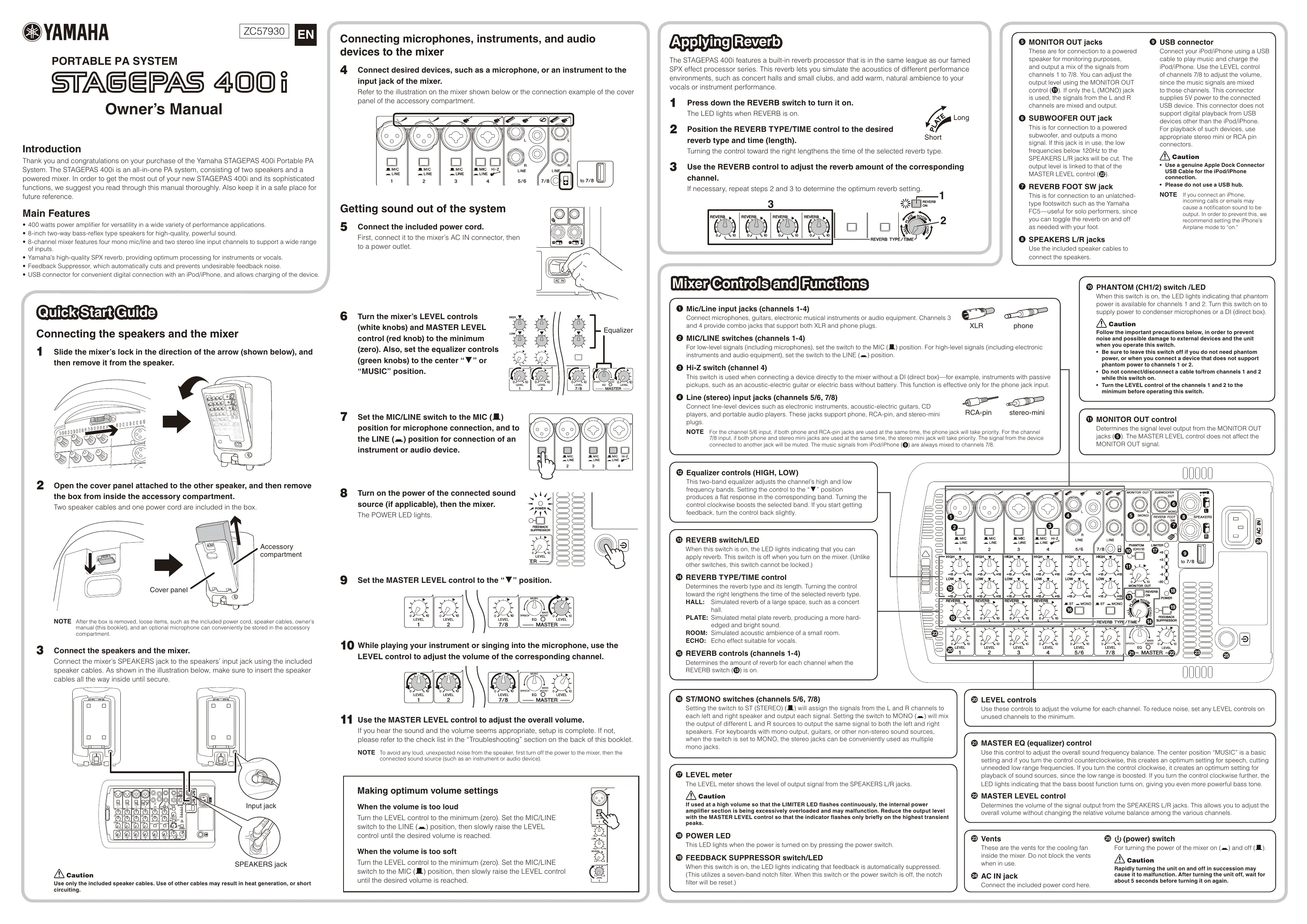
PORTABLE PA SYSTEM
STAGEPAS 400i
Owner's Manual
Introduction
Thank you and congratulations on your purchase of the Yamaha STAGEPAS 400i Portable PA System. The STAGEPAS 400i is an all-in-one PA system, consisting of two speakers and a powered mixer. In order to get the most out of your new STAGEPAS 400i and its sophisticated functions, we suggest you read through this manual thoroughly. Also keep it in a safe place for future reference.
Main Features
- 400 watts power amplifier for versatility in a wide variety of performance applications
- 8-inch two-way bass-reflex type speakers for high-quality, powerful sound.
- 8-channel mixer features four mono mic/line and two stereo line input channels to support a wide range of inputs.
- Yamaha's high-quality SPX reverb, providing optimum processing for instruments or vocals
- Feedback Suppressor, which automatically cuts and prevents undesirable feedback noise.
- USB connector for convenient digital connection with an iPod/iPhone, and allows charging of the device.
QuickStartGuide
Connecting the speakers and the mixer
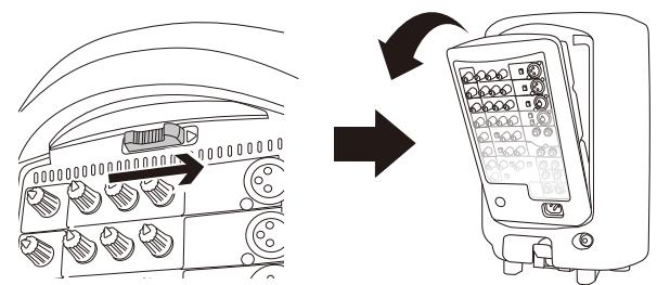
1 Slide the mixer's lock in the direction of the arrow (shown below), and then remove it from the speaker.
2 Open the cover panel attached to the other speaker, and then remove the box from inside the accessory compartment.
Two speaker cables and one power cord are included in the box.
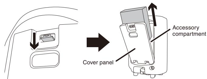
NOTE After the box is removed, loose items, such as the included power cord, speaker cables, owner's manual (this booklet), and an optional microphone can conveniently be stored in the accessory compartment.
3 Connect the speakers and the mixer.
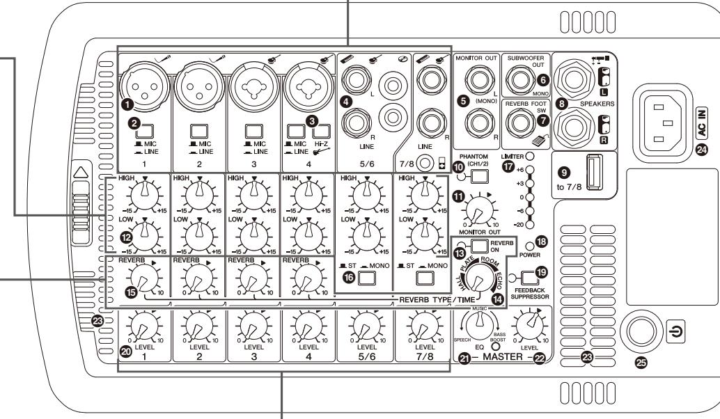
- Connect the mixer's SPEAKERS jack to the speakers' input jack using the included speaker cables. As shown in the illustration below, make sure to insert the speaker cables all the way inside until secure.
SPEAKERS jack

Caution
Use only the included speaker cables. Use of other cables may result in heat generation, or short circuiting.
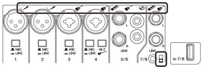
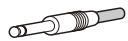
Connecting microphones, instruments, and audio devices to the mixer
4 Connect desired devices, such as a microphone, or an instrument to the input jack of the mixer.
Refer to the illustration on the mixer shown below or the connection example of the cover panel of the accessory compartment.
Getting sound out of the system
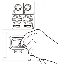
5 Connect the included power cord.
First, connect it to the mixer's AC IN connector, then to a power outlet.
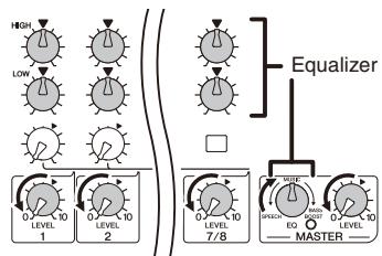
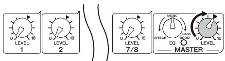
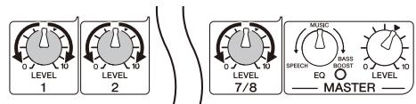
6 Turn the mixer's LEVEL controls (white knobs) and MASTER LEVEL control (red knob) to the minimum (zero). Also, set the equalizer controls (green knobs) to the center "▼" or "MUSIC" position.
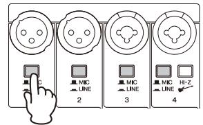
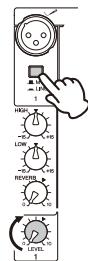
7 Set the MIC/LINE switch to the MIC (■) position for microphone connection, and to the LINE (■) position for connection of an instrument or audio device.
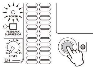
8 Turn on the power of the connected sound source (if applicable), then the mixer. The POWER LED lights.
9 Set the MASTER LEVEL control to the “ ” position.
10 While playing your instrument or singing into the microphone, use the LEVEL control to adjust the volume of the corresponding channel.
11 Use the MASTER LEVEL control to adjust the overall volume.
If you hear the sound and the volume seems appropriate, setup is complete. If not, please refer to the check list in the "Troubleshooting" section on the back of this booklet.
NOTE To avoid any loud, unexpected noise from the speaker, first turn off the power to the mixer, then the connected sound source (such as an instrument or audio device).
Making optimum volume settings
When the volume is too loud
Turn the LEVEL control to the minimum (zero). Set the MIC/LINE switch to the LINE () position, then slowly raise the LEVEL control until the desired volume is reached.
When the volume is too soft
Turn the LEVEL control to the minimum (zero). Set the MIC/LINE switch to the MIC (■) position, then slowly raise the LEVEL control until the desired volume is reached.
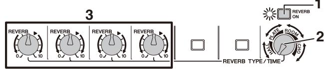
ApplyingReverb
The STAGEPAS 400i features a built-in reverb processor that is in the same league as our famed SPX effect processor series. This reverb lets you simulate the acoustics of different performance environments, such as concert halls and small clubs, and add warm, natural ambience to your vocals or instrument performance.
1 Press down the REVERB switch to turn it on.
The LED lights when REVERB is on.
2 Position the REVERB TYPE/TIME control to the desired reverb type and time (length).
Turning the control toward the right lengthens the time of the selected reverb type.
3 Use the REVERB control to adjust the reverb amount of the corresponding channel.
If necessary, repeat steps 2 and 3 to determine the optimum reverb setting.

Short
⑤ MONITOR OUT jacks
These are for connection to a powered speaker for monitoring purposes, and output a mix of the signals from channels 1 to 7/8. You can adjust the output level using the MONITOR OUT control (1). If only the L (MONO) jack is used, the signals from the L and R
channels are mixed and output.
SUBWOOFER OUT jack
This is for connection to a powered subwoofer, and outputs a mono signal. If this jack is in use, the low frequencies below 120Hz to the SPEAKERS L/R jacks will be cut. The output level is linked to that of the MASTER LEVEL control (2).
7 REVERB FOOT SW jack
This is for connection to an unlatched-type footswitch such as the Yamaha FC5—useful for solo performers, since you can toggle the reverb on and off as needed with your foot.
USB connector
Connect your iPod/iPhone using a USB cable to play music and charge the iPod/iPhone. Use the LEVEL control of channels 7/8 to adjust the volume, since the music signals are mixed to those channels. This connector supplies 5V power to the connected USB device. This connector does not support digital playback from USB devices other than the iPod/iPhone. For playback of such devices, use appropriate stereo mini or RCA pin connectors.
Caution
- Use a genuine Apple Dock Connector USB Cable for the iPod/iPhone connection.
- Please do not use a USB hub.
NOTE If you connect an iPhone, incoming calls or emails may cause a notification sound to be output. In order to prevent this, we recommend setting the iPhone's Airplane mode to "on."
Mixer Controls and Functions
1 Mic/Line input jacks (channels 1-4)
Connect microphones, guitars, electronic musical instruments or audio equipment. Channels 3 and 4 provide combo jacks that support both XLR and phone plugs.
MIC/LINE switches (channels 1-4)
For low-level signals (including microphones), set the switch to the MIC (■) position. For high-level signals (including electronic instruments and audio equipment), set the switch to the LINE (—) position.
Hi-Z switch (channel 4)
This switch is used when connecting a device directly to the mixer without a DI (direct box) for example, instruments with passive pickups, such as an acoustic-electric guitar or electric bass without battery. This function is effective only for the phone jack input.
Line (stereo) input jacks (channels 5/6, 7/8)
Connect line-level devices such as electronic instruments, acoustic-electric guitars, CD players, and portable audio players. These jacks support phone, RCA-pin, and stereo-mini plugs.
NOTE For the channel 5/6 input, if both phone and RCA-pin jacks are used at the same time, the phone jack will take priority. For the channel 7/8 input, if both phone and stereo mini jacks are used at the same time, the stereo mini jack will take priority. The signal from the device connected to another jack will be muted. The music signals from iPod/Phone (9) are always mixed to channels 7/8.

XLR
phone

phone
Equalizer controls (HIGH, LOW)
This two-band equalizer adjusts the channel's high and low frequency bands. Setting the control to the "▼" position produces a flat response in the corresponding band. Turning the control clockwise boosts the selected band. If you start getting feedback, turn the control back slightly.
15 REVERB switch/LED
When this switch is on, the LED lights indicating that you can apply reverb. This switch is off when you turn on the mixer. (Unlike other switches, this switch cannot be locked.)
REVERB TYPE/TIME control
Determines the reverb type and its length. Turning the control toward the right lengths the time of the selected reverb type HALL: Simulated reverb of a large space, such as a concert
PLATE: Simulated metal plate reverb, producing a more hard-edged and bright sound.
ROOM: Simulated acoustic ambience of a small room
ECHO: Echo effect suitable for vocals.
15 REVERB controls (channels 1-4)
Determines the amount of reverb for each channel when the REVERB switch (8) is on.
16 ST/MONO switches (channels 5/6, 7/8)
Setting the switch to ST (STEREO) will assign the signals from the L and R channels to each left and right speaker and output each signal. Setting the switch to MONO will mix the output of different L and R sources to output the same signal to both the left and right speakers. For keyboards with mono output, guitars, or other non-stereo sound sources, when the switch is set to MONO, the stereo jacks can be conveniently used as multiple mono jacks.
LEVEL meter
The LEVEL meter shows the level of output signal from the SPEAKERS L/R jacks.

If used at a high volume so that the LIMITER LED flashes continuously, the internal power amplifier section is being excessively overloaded and may malfunction. Reduce the output level with the MASTER LEVEL control so that the indicator flashes only briefly on the highest transient peaks.
16 POWER LED
This LED lights when the power is turned on by pressing the power switch.
FEEDBACK SUPPRESSOR switch/LED
When this switch is on, the LED lights indicating that feedback is automatically suppressed. (This utilizes a seven-band notch filter. When this switch or the power switch is off, the notch filter will be reset.)
LEVEL controls
Use these controls to adjust the volume for each channel. To reduce noise, set any LEVEL controls on unused channels to the minimum.
3 MASTER EQ (equalizer) control
Use this control to adjust the overall sound frequency balance. The center position "MUSIC" is a basic setting and if you turn the control counterclockwise, this creates an optimum setting for speech, cutting unneeded low range frequencies. If you turn the control clockwise, it creates an optimum setting for playback of sound sources, since the low range is boosted. If you turn the control clockwise further, the LED lights indicating that the bass boost function turns on, giving you even more powerful bass tone.
2 M A S T E R L E V E L control
Determines the volume of the signal output from the SPEAKERS L/R jacks. This allows you to adjust the overall volume without changing the relative volume balance among the various channels.
23 Vents
These are the vents for the cooling fan inside the mixer. Do not block the vents when in use.
(power) switch
For turning the power of the mixer on (1) and off (1)

AC IN jack
Connect the included power cord here.
Rapidly turning the unit on and off in succession may cause it to malfunction. After turning the unit off, wait for about 5 seconds before turning it on again.
Troubleshooting
Power does not turn on.
Did you firmly and securely connect the power cord?
Power shuts down suddenly.
Are the vents of the mixer blocked?
Since inadequate ventilation can result in overheating the mixer, the power may be turned off automatically to protect from overheating. Secure the ventilation for cooling, then turn on the power again.
No sound is heard.
- Did you connect the mixer's SPEAKERS jacks and the speakers' input jacks using the proper speaker cables?
Did you firmly and securely connect the speaker cables?
Is a speaker other than the included speaker (MODEL 400S) connected to the mixer's SPEAKERS jacks? Please connect the included speaker (MODEL 400S).
- Did you use the included speaker cables? If you use a commercially-available speaker cable with a metal-housing connector, the cable will be shorted
when the connector touches other metal, resulting in no sound being produced.
Is the POWER LED flashing at intervals? There may be a short in the speaker cable or the connection may be faulty. Check that the speaker cable is not scratched and is connected properly to the mixer, then reapply the power.
For channels 5/6, are both phone and RCA-pin jacks connected at the same time? Or, for channels 7/8, are both phone and stereo mini jacks connect at the same time?
The phone jack has priority for channels 5/6 and the stereo mini jack has priority for 7/8.
Is the POWER LED flashing continuously?
If the internal power amplifier section is excessively overloaded, the amplifier will be muted for protection. The mixer will automatically reset itself after a while.
Sound is distorted or noise is produced
Are the LEVEL controls of all relevant channels and/or the MASTER LEVEL control set too high?
Is the MIC/LINE switch of the corresponding channel set to MIC?
If the input level from the source is high, setting the MIC/LINE switch to MIC may result in distorted sound. Set the switch to LINE position.
Is the volume of the connected device too high?
Lower the volume of the external device
Is the speaker cable or the power cord located near the input cables?
Please keep it away from the input cables
Sound is not loud enough
Are the LEVEL controls of all relevant channels and/or the MASTER LEVEL control set too low?
Is the MIC/LINE switch of the corresponding channel set to LINE? Turn the LEVEL control to the minimum (zero). Set the switch to the MIC position then slowly raise the LEVEL control.
Is the volume of the connected device too low?
Raise the volume of the external device.
Is the PHANTOM switch set to on when using a microphone that requires phantom power?
The high sounds and low sounds are unbalanced.
Are the equalizer controls raised or lowered too much?
Set the equalizer controls to the center position.
Is the speaker properly outputting the high-frequency range signals?
If not, check the "Protective circuit (poly switch)" note in the Notice section.
iPod/iPhone is not recognized
Is your iPod/iPhone charged?
If your iPod/Phone has not been charged, it may take some time to be recognized by the mixer. Make sure that your iPod/Phone is connected to the mixer and wait until it is sufficiently charged.
- If any specific problem should persist, please contact your Yamaha dealer.
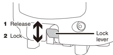
Attaching a speaker to a speaker stand
1 Attach the speaker to the speaker stand with the lock lever moved up (release position).
2 Move the lock lever down to lock to the stand.
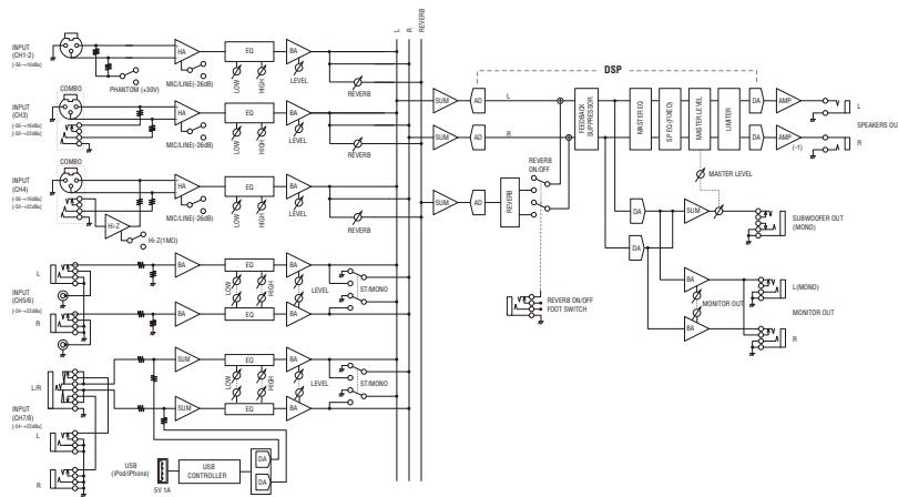
Block Diagram
Specifications
General Specifications
Maximum Output Power (SPEAKERS L/R)
200 W + 200 W/4 Ω @Dynamic at 1 kHz- 180 W - 180 W/4 Ω @10% THD at 1 kHz
125 W+125W/40@1%THD at 1kHz
Frequency Response
-3 dB, +1 dB @ 40 Hz-20 kHz, 1 W Output/4Ω
(without EQ and SP EQ) (SPEAKERS L/R) -3 dB, +1 dB @ 40 Hz-20 kHz, +4 dBu 10 kΩ Load (MONITOR OUT)
Total Harmonic Distortion
≤0.5 % @20 Hz-20 kHz, +11 dBu 10 kΩ (MONITOR OUT)
Hum & Noise (Rs=150 Ω, MIC/LINE switch=MIC)
≤60 dBu Residual output noise (SPEAKERS L/R)
rosstalk (1 kHz)
≤-70 dB between input channels
Phantom Voltage
+30 V (CH1, 2)
Weight
17.8 kg (39.2 lbs) (Speaker 7.5 kg x 2 + Mixer 2.8 kg)
Package Contents
STAGEFAS 40U1 (Includes two MODEL 40US Speakers and a Powered Mixer), Cover Panel, Power Cord (2m), two Speaker Cables (6m), 12 Non-Skid Pads, Owner's Manual (this booklet)
Power Consumption
30 W (Idle), 70
Power Requirement
100V-240V50Hz/60Hz
Input Channel Equalization
±15dB
M18.1-6kH2 shelving LOW: 100 Hz shelving
Supported iPod/iPhone models (as of August 2012)
iPod touch (1st, 2nd, 3rd, and 4th generation),
iPod classic, iPod nano (21fd, 3rd, 4th, 5th, and 6th generation), iPhone 4S, iPhone 4, iPhone 3GS, iPhone 3G, iPhone
For updated information, check the Yamaha Pro Audio
■ Speakers (MODEL 400S)
Enclosure
2 way bass-reflex type
Speaker Unit
LF: 8^ (20 cm) Cone
HF:1 (2.54 cm) Compression Driver
Crossover Frequency
3.2kH
Frequency Range
55 Hz-20 kHz (-10 dB)
Maximum Output Level
125 dB SPL (Measured peak IEC noise@1m)
Coverage Angle
90° (Horizontal)/60° (Vertical)
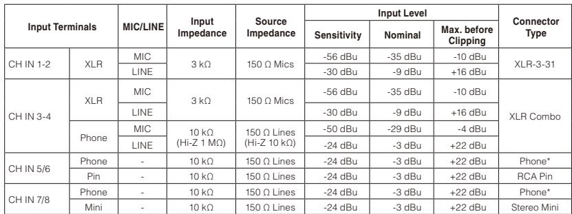
Input Characteristics
Output Characteristics
| Output Terminals | Output Impedance | Load Impedance | Output Level | Connector Type | |||
| Nominal | Max. before Clipping | Typ at THD+N 10% | Dynamic | ||||
| SPEAKERS OUT [L,R] | <0.1 Ω | 4 Ω Speakers | 37.5 W | 125 W | 180 W | 200 W | Phone* |
| MONITOR OUT [L,R] | 600 Ω | 10 kΩ Lines | +4 dBu | +20 dBu | - | - | Phone* |
| SUBWOOFER OUT | 150 Ω | 10 kΩ Lines | -3 dBu | +17 dBu | - | - | Phone* |
0 dBu=0.775 Vrms, 0 dBV=1 Vrms Phone*: Unbalanced
Specifications and descriptions in this owner's manual are for information purposes only. Yamaha Corp reserves the right to change or modify products or specifications at any time without prior notice. Since specifications, equipment or options may not be the same in every locale, please check with your Yamaha dealer.
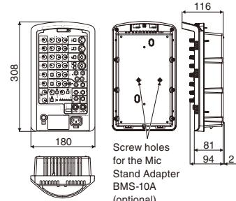
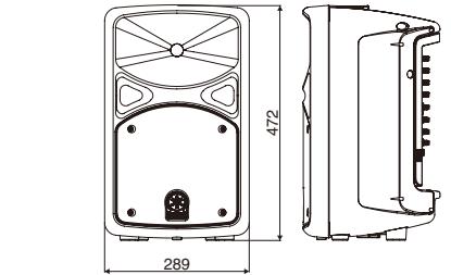
Dimensions
Mixer
Speaker
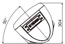
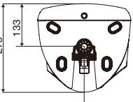
Pole diameter 34.8 - 35.
* Use of the stand should refer to stand
manufacturer's instructions
Do not open
- This device contains no user-serviceable parts. Do not open the device or attempt to disassemble the internal parts or modify them in any way. If it should appear to be malfunctioning, discontinue use immediately and have it inspected by qualified Yamahara service personnel.
Water warning
-
Do not expose the device to rain, use it near water or in damp or wet conditions, or place on it any containers (such as vases, bottles or glasses) containing liquids which might spill into any openings. If any liquid such as water seeps into the device, turn off the power immediately and unplug the power cord from the AC outlet. Then have the device inspected by qualified Yamaha service personnel.
-
Never insert or remove an electric plug with wet hands.
Fire warning
- Do not put burning items, such as candies, on the unit. A burning item may fall over and cause a fire.
If you notice any abnormality
- When one of the following problems occur, immediately turn off the power switch and disconnect the electric plug from the outlet. Then have the device inspected by Yamahara service personnel.
- The power cord or plug becomes frayed or damaged.
- It emits unusual smells or smoke.
Some object has been dropped into the instrument. There is a sudden loss of sound during use of the de - If this mixer should be dropped or damaged, immediately turn off the power switch, disconnect the electric plug from the outlet, and have the device inspected by qualified Yamaha service personnel.
CAI
Always follow the basic precautions listed below to avoid the possibility of physical injury to you or others, or damage to the device or other property. These precautions include, but are not limited to, the following:
Power supply/Power cord
- When removing the electric plug from the device or an outlet, always hold the plug itself and not the cord. Pulling by the cord can damage it.
- Remove the electric plug from the outlet when the device is not to be used for extended periods of time, or during electrical storms.
Location
- Do not place the device in an unstable position. Unless the device is securely affixed, do not install it in a location where it might fall, even if the surface is level.
-
Do not block the vents. This mixer has ventilation holes at the top and sides to prevent the internal temperature from becoming too high. In particular, do not place the mixer on its side or upside down. Inadequate ventilation can result in overheating, possibly causing damage to the mixer, or even fire.
-
Do not use the device in a confined, poorly-ventilated location. Make sure that there is adequate space between the mixer, or the speaker fitted with the mixer, and surrounding walls or other devices: at least 30cm at the sides, 30cm behind and 30cm above. Inadequate ventilation can result in overheating, possibly causing damage to the device(s), or even fire.
-
If you lay the speaker flat on its side or like a stage monitor, make sure to remove the mixer first.
- Do not hold the bottom of the speaker when transporting or moving it. In doing so, you may pinch your hands under the speaker, and result in injury.
- Do not place the device in a location where it may come into contact
with corrosive gases or salt air. Doing so may result in malfunction. - Before moving the device, remove all connected cables.
- When setting up the mixer, make sure that the AC outlet you are using is easily accessible. If some trouble or malfunction occurs, immediately turn off the power switch and disconnect the plug from the outlet. Even when the power switch is turned off, electricity is still flowing to the product at the minimum level. When you are not using the product for a long time, make sure to unplug the power cord from the wall AC outlet.
Connections
- Before connecting the device to other devices, turn off the power for all devices. Before turning the power on or off for all devices, set all volume levels to minimum.
- For the SPEAKERS jacks of the mixer, use only the included MODEL 400S speakers and speaker cables. Use of other types of speakers and cables may result in damage, or even fire.
Maintenance
- Remove the power plug from the AC outlet when cleaning the device
Handling caution
- Do not insert your fingers or hands in any gaps or openings on the vents or panel of the mixer and the ports of the speaker.
- Avoid inserting or dropping foreign objects (paper, plastic, metal, etc.) into any gaps or openings on the vents or panel of the mixer and the ports of the speaker. If this happens, turn off the power immediately and unplug the power cord from the AC outlet. Then have the device inspected by qualified Yamahara service personnel.
- Do not rest your weight on the device or place heavy objects on it, and avoid use excessive force on the buttons, switches or connectors.
- Do not use the speakers for a long period of time at a high or uncomfortable volume level, since this can cause permanent hearing loss. If you experience any hearing loss or ringing in the ears, consult a physician.
- Do not operate the device if the sound is distorting. Prolonged use in this condition could cause overheating and result in fire.
- Do not pull on any attached cable, such that of a microphone. Doing so may cause the speaker to topple, and result in damage or in injury.
Yamahara cannot be held responsible for damage caused by improper use or modifications to the device, or data that is lost or destroyed.
PA_en_1
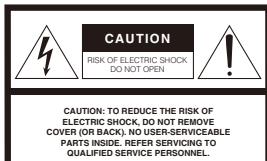
Explanation of Graphical Symbols
The lightning flash with arrowhead symbol within an equilateral triangle is intended to alert the user to the presence of uninsulated "dangerous voltage" within the product's enclosure that may be of sufficient magnitude to constitute a risk of electric shock to persons.
The exclamation point within an equilateral triangle is intended to alert the user to the presence of important operating and maintenance (servicing) instructions in the literature accompanying the product.
The above warning is located on the bottom of the mixer
IMPORTANT SAFETY INSTRUCTIONS
-
Read these instructions.
-
Keep these instructions
-
Heed all warnings. 4. Follow up with the work.
I. Do not use this inc
-
Clean only with dry cloth
-
Do not block any ventilation openings. Install in accordance with the
manufacturer's instruction
-
Do not install near any heat sources such as radiators, heat registers, stoves, or other apparatus (including amplifiers) that produce heat.
-
Do not defeat the safety purpose of the polarized or grounding-type plug. A polarized plug has two blades with one wider than the other. A grounding type plug has two blades and a third grounding prong. The wide blade or the third prong are provided for your safety. If the provided plug does not fit into your outlet, consult an electrician for replacement of the obsolete outlet.
-
Protect the power cord from being walked on or pinched particularly at plugs,
convenience receptacles, and the point where they exit from the apparatus. - Use only with the cart, stand, tripod, bracket, or table specified by the manufacturer, or sold with the apparatus. When a cart is used, use caution when moving the cart/
- Unplug this apparatus during lightning storms or when unused for long periods of time.
- Refer all servicing to qualified service personnel. Servicing is required when the apparatus has been damaged in any way, such as power-supply cord or plug is damaged, liquid has been spilled or objects have fallen into the apparatus, the apparatus has been exposed to rain or moisture, does not operate normally, or has been dropped.
(UL60065_03)
JL60065_03)
IT! product is found
product is found to be the source of interference, which can be determined by
turning the unit- GP^ and GP ,please by it to eliminate the problem by using one of the following measures: Relocate either this product or the device that is being affected by the interference.
Utilize power outlets that are on different branch (circuit breaker or fuse) circuits or install AC line filter/s.
In the case of radio or TV interference, relocate/record the antenna. If the antenna lead-in is 300 ohm ribbon lead, change the lead-in to co-axial type cable.
If these corrective measures do not produce satisfactory results, please contact the local retailer authorized to distribute this type of product. If you can not locate the appropriate retailer, please contact Yamaha Corporation of America, Electronic Service Division, 6600 Orangelthorpe Ave, Buena Park, CA90620 The above statements apply ONLY to those products distributed by Yamaha Corporation of America or its subsidiaries.
(class B)
此工具栏的名称(如图1-2)或“当前可选择工具栏”则不是为当前设置上,所以通常的设置是先将该属性设置为“所有”。在设置中,只要选择“所有”,就会自动显示。
(class b korea)
( x - 2x) t - xy^2 = ( x - 2x) f^ t
( x - 2x) t - xy^2 = ( x - 2x) f^ t
( x - 2x) t - xy^2 = ( x - 2x) f^ t
(
For details of products, please contact your nearest Yamaha representative or the authorized distributor listed below
NORTH AMERICA
CANADA Number of Canada Ministry Ltd.
135 Milner Avenue, Scarborough, Ontario, Canada
M3S 3R1, Canada Tel: 416-298-1311
S.A.
Yamaha Corporation of America 6680-0000, Japan
U.S.A.
Tel: 714-522-9011
CENTRAL & SOUTH AMERICA
CENTRAL & SOCIETY
Yamaha de Mexico S.A. de C.V.
Calz.Javier Rojo Gomez #1149
C.P.09300, Mexico.D.E., Mex
Tel: 55-5804-0600
RAZIL
Yamala Musical do Brasil Ltda. Rua Joaquim Floriano, 913 - 4' andar. Itaim Bibi
Jean-Sourceu Hantou, 913-4706 CEP 04534-013 Sao Paulo, SP.
Tel: 011-3704-1
RGENTINA
Yamaha Music Latin America, S. Seurgal de Argentina
Olga Cossettini 1553, Piso 4 Na
Madero Este-C1107CEK
Buenos Aires, Argentina
Tel: 011-4119-7000
ANAMA AND OTHERS
MERICAN COUNTRIES/
ARIBBEAN COUNTRY
Yamada Music Latin America, S.A.
Tampa Rondo General, Pine 7, Urbanosa-Marthole
Calle 47 y Aquilino de la Guard
Cuidad de Panama, Panama
1067
EUROPE
THE UNITED KINGDOM/IRELAND
Yamaha Music Europe GmbH (UK)
Sherbourne Drive, Tilbrook, Milton Keynes, MK70 8PL, England
MK/ABL,England Tel:01908-366700
ERMANY
Yamaha Music Europe GmbH
Siemensstraße 22-34, 25462 Rellingen, Germany Tel: 04101-3030
10141530600 NITTEPLAND/LEGUT
WITZEREX/EDICHEY
Yamaha Music Europe GmbH
Branch Switzerland in Zurich
Seefeldstrasse 94, 8008 Zürlen, Switzerland Tel: 044-397-8998
TE.044-587-6808 IUSTRIA/BULCARIA
UARABULAKA
Yamaha Music Europe GmbH Branch Austria
Schleiergasse 20, A-1100 Wien, Austria
Tel: 01-60203900
ZECH REPUBLIC/HUNGARY/OMANIA/SLOVAKIA/SLOVEN
Yamaha Music Europe GmbH
Branch Austria (Central Eastern Europe Office)
Schleiergasse 20, A-1100 Wien, Austria
Tel: 01 602039025
OLAND/LITHUANIA/LA
Yamaha Music Europe GmbH
Branch Poland Office a. Wrothow 1402-553 Warsaw, Poland
Dr. Wiotkowa 14 02-333 Warsaw, Poland Tel: 022-500-2925
ALTA Olimpus Music Ltd.
The Emporium, Level 3, St. Louis Street Msida
1SD06
Tel:02133-2144 THE NETHERLANDS
LIGUM/LUXEMBOURG
Jamaha Music Europe Branch
Jarissenhof 5-6,4133 AB Vianen, The Netherlands 40317-218-019
EL 0547-538 040
ANCE
JANICE
Jamaha Music Europe
P 70-77312 Marne-la-Vallee Cedex 2, France
el:01-64-61-4000
ALY
Ammanna Music Europe GmbH, Branch Italy
fich Italy 88, 20020 Ljatno (Milan), Italy
Rate Ratio 0.04-0.06: Lactate (M) [mol]: 02-935-771
AIN/PORTUGAL
Tamaha Music Europe GmbH Ibérica, Sucursal 1
n Espana 17-208-20239
as Rozas (Madrid), Spain
el: +34
REECE
Philippos Nakas S.A. The Music House
47 Siaikhou Street, 112-35 Athens, Greece
el:01-228.2160
YEDEN/FINLAND/ICELAND
LEBENFENBACHSANDA
amaha Music Europe GmbH Germany filial
caninavia
A. Wettergrens Gata 1, Box 30053, 400-43 Gathorsga, Sweden
el:031893
ENMARK
Yamaha Music Europe GmbH, Tyskland - filial
Denmark
Generatorve6A,DK-2730 HerlevDenmark 44-92-48-00
ORWAY
RWMH
Jamaha Music Europe GmbH Germany
Norwegian Branch
Jirini Næringspark 1, N-1345 Osteras, Norway
el:6/16 2021-4
SSIA imaba Mria (Praia)
amana Music (Russia)
room 37, bld. 7, Kievskaya street, Moscow
21059, Russia
el:4956265005
OTHER EUROPEAN COUNTRIES
amaha Music Europe GmbH
demenstralle 22-34, 25462 Reilingen, Germany; +49.4101.3030
AFRICA
Jamaha Co.
Asia-Pacific Sales & Marketing Group
akazawa-cho 10-1, Naka-ku, Hamamatsu, 428-8659
Japan: +81 53,460,2303
MIDDLE EAST
IRKEY/CYPRUS
Famaha Music Europe GmbH
Flemensstraße 22-34, 25462 Rellingen, Germany
Tel:04101-3030 Tel:04101-3030
HER COUNTRIES
OB 16-513, PO Box 17328, Jubel Ali
Kubai, United Arab Emirates
el: +971-4-881-5868
ASIA
3 REPUBLIC OF CHINA
: Electronics (China) Co., Ltd.
818 Xinhua-1u, Jingan-Qu,
- 顺
A
India Pvt. Ltd.
Ground Floor, Tower A, Sec. 1
Sha Road, Gurgaon, Haryana, India
1
HK Indonesia (Distributer)
Furaya Center, Iden Land, Gata
karta 12930, Indonesia
”
EA
Korea Ltd
Bldg. 158-9 Samsung-Dong,
JUL, Korea
1
A
Malaysia) Suni, Bhd.
Inderan 47301 Kalong Jaya
Angor, Malaysia
Asia) PRIVATE LIMITED
Street 21,#02-00,
Bris Co. Ltd.
Jing E.Rd.Taine
:
Jana Co., Ltd.
Sao Chi Minh City, Vietnam
Roo, Sham Motors Building, and Wangmei
kok 10330. Thailand
COUN
ation,
s & Marketing Group
-1, Naka-Ku, Haimailatsu,
。
OCEAN
Australia Pty. Ltd.
bridge Street, Southbank,
ND TRUST
IN PACIFIC OCEAN
Inactivity 6
s&MarketingGroup
-1, Naka-ku, Hamamatsu,
202
m = 311 ;
HEAD OFFICE Yamaha Corporation, Pro Audio Division
Nakazawa-cho 10-1, Naka-ku, Hamamatsu, Japan 430-8650 Tel: +81-52-469-2441
al of
#
PORTANT NOTICE FOR THE UNITED
Connecting the Plug and Cord
Connecting the Plug and Cord
WARNING: THIS APPARATUS MUST BE EARTHED IMPORTANT. The wires
lead are colour.
GREEN-AND-YELLOW : EARTHBLUE NEUTRAL
BLOE NEUTRAL BROWN LINE
BROWN
As the colours of the wires in the mains lead of this apparatus may not correspond with the coloured markings identifying the terminals in your plug proceed as follows:
The wire which is coloured GREEN-and-YELLOW must be connected to the terminal in the plug which is marked by the letter E or by the safety earth symbol ④ or colored GREEN or GREEN-and-YELLOW.
The wire which is coloured BLUE must be connected to the terminal which is marked with the letter N or coloured BLACK.
The wire which is coloured BROWN must be connected to the terminal which is marked with the letter L or coloured RED.
(3 wires)
A31
Yamaha Pro Audio global web site
http://www.yamahaaproaudio.com/
Yamaha Manual Library
http://www.yamaha.co.jp/manual
C.S.G., Pro Audio Division
208MWHD*1-01A0
Printed in China
(weee_eu)