LQC1B-V1 - Dimmer EtiamPro - Gratis gebruiksaanwijzing en handleiding
Vind de handleiding van het apparaat gratis LQC1B-V1 EtiamPro in PDF-formaat.
| Type product | Variateur (dimmer) |
| Merk | EtiamPro |
| Model | LQC1B-V1 |
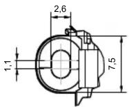
| Afmetingen (H x B x D) | 80 x 80 x 40 mm (geschat) |
| Gewicht | Ongeveer 100 g |
| Voeding | 230 V AC, 50/60 Hz |
| Maximale belasting | 400 W (gloeilampen) / 150 W (LED) |
| Dimbereik | 0-100% (afhankelijk van lamp) |
| Functies | Dimmen, aan/uit, soft start |
| Installatie | Inbouw in wanddoos, geschikt voor enkelpolige schakeling |
| Geschikte lampen | Gloeilampen, halogeen, dimbare LED, dimbare CFL |
| Beschermingsgraad | IP20 (binnengebruik) |
| Omgevingstemperatuur | -10 °C tot +40 °C |
| Kleur | Wit (RAL 9010) |
| Materiaal | Kunststof, hittebestendig |
| Veiligheid | Overbelastingbeveiliging, kortsluitbeveiliging |
| Onderhoud en reiniging | Afnemen met droge doek; geen vloeistoffen gebruiken |
| Garantie | 2 jaar |
| CE-markering | Ja |
Veelgestelde vragen - LQC1B-V1 EtiamPro
Gebruikersvragen over LQC1B-V1 EtiamPro
0 vraag over dit apparaat. Beantwoord die u kent of stel uw eigen vraag.
Stel een nieuwe vraag over dit apparaat
Download de handleiding voor uw Dimmer in PDF-formaat gratis! Vind uw handleiding LQC1B-V1 - EtiamPro en neem uw elektronisch apparaat weer in handen. Op deze pagina staan alle documenten die nodig zijn voor het gebruik van uw apparaat. LQC1B-V1 van het merk EtiamPro.
GEBRUIKSAANWIJZING LQC1B-V1 EtiamPro
etiampro:P
LQC1B-V1 Single channel
EASY DIMMER
Data Sheet
FW 3.0+
Rev. 2018-01-22
pag. 1/4

text_image
etiampro 5V 0V IN PUSH N.O. SINGLE CHANNEL LED DIMMER LOC18-V7 DC IN: 12-48 V OUT: max. 6 A DC IN OUT + - L+ L- CECE
FEATURES
• FADER+DIMMER+DRIVER
• DC Input: 12/24/48 Vdc
• Command: N.O. push button
- Adjusting the brightness of white light
- Current outputs or voltage outputs for R-L-C loads
• Typical efficiency > 95%
- Adjusting the brightness up to completed off
- Soft start and soft stop
- Optimized output curve
- Extended temperature range
• 100% Functional test - 5 Years warranty
Constant voltage variants (common anode)
| CODE Supply voltage Output Channel Command | ||||
| LQC1B-V1 12-48V DC 1 x 8A max 1 N.O. push button |
Application: Dimmer
Protections
| OTP | Over temperature protection |
| OVP | Over voltage protection (*) |
| UVP | Under voltage protection (*) |
| RVP | Reverse polarity protection (*) |
| IFP | Input fuse protection (*) |
| SCP | Short circuit protection |
| OCP | Open circuit protection |
| CLP | Current limit protection |
(*) Only control logic protection
Reference standards
| EN 61347-1:2008 +A1:2011+A2:2013 Lamp controlgear - Part 1: General and safety requirements |
| EN 55015:2013+A1:2015 Limits and methods of measurement of radio disturbance characteristics of electrical lighting and similar equipment |
| EN 61547:2009 Equipment for general lighting purposes - EMC immunity requirements |
| EN 50581:2012 Technical documentation for the assessment of electrical and electronic products with respect to the restriction of hazardous substances |
Technical Specifications
| Variants | ||
| Constant Voltage | ||
| Supply voltage min: 10,8 Vdc .. max: 52,8 Vdc | ||
| Input current max 8 A peak | ^1) | |
| Output voltage = Vin | ||
| Output current max 8 A peak | ^1) max 7,5A @20°C ^2) max 6,5A @40°C ^2) | |
| Nominal power ^1) | @12V 78 W | |
| @24V 156 W | ||
| @48V 312 W | ||
| Thermal shutdown 150 °C | ||
| D-PWM dimming frequency 250Hz | ||
| D-PWM resolution 16 bit | ||
| D-PWM range 1 – 100 % | ||
| Storage Temperature min: -40 max: +60 °C | ||
| Ambient Temperature ^2) | min: -10 max: +40 °C | |
| Protection grade IP20 | ||
| Wiring 2.5mm ^2 solid - 1.5mm ^2 stranded - 30/12 AWG | ||
| Mechanical dimensions | 45 x 58 x 25 mm | |
| Packaging dimensions | 68 x 56 x 35 mm | |
| Weight | 40g | |
^15 maximum value, dependent on ventilation conditions
Installation
Connect the switching supply (12-48V), connect the N.O. push button (to 5 or 0V, with/without memory), connect leds.

text_image
LN PE 230V SWITCHING SUPPLY 12-48Vdc Vout + - *connected to 5V = MEMORY *connected to 0V = NO MEMORY N.O. push button 5V 0V IN PUSH N.O. SINGLE CHANNEL LED DIMMER LOC:38-V1 DC In: 12-48 V OUT: max. 0 A DC IN OUT + - L+ L- DC IN 12/24/48 VdcConfiguration
N.O. PUSH BUTTON
1- Memory function: the device stores its state in case of blackout (if N.O. push buttons connected to 5V).
2- Eco function: when recovering the power supply the device starts-up from a switched off condition (if N.O. push buttons connected to 0V).
3- Preset function: when recovering the power supply the device starts-up from a previously set condition. The preset can be stored by connecting N.O. push buttons to 5V during installation (and to 0V after installation).
Function
N.O. PUSH BUTTON
The intensity and the status (ON/OFF) is controlled by the N.O. push button.
| Button Function | ty | |
| 1 | ClickDouble ClickLong pressure (>1s) from OFFLong pressure (>1s) from ON | |
Mechanical Dimension

Technical Notes
Installation:
• Installation and maintenance must be performed only by qualified personnel in compliance with current regulations.
• The product must be installed inside an electrical panel protected against overvoltages.
- The product must be installed in a vertical or horizontal position with the cover / label upwards or vertically; Other positions are not permitted. It is not permitted to bottom-up position (with the cover / label updown).
- Keep separated the circuits at 230V (LV) and the circuits not SELV from circuits to low voltage (SELV) and from any connection with this product. It is absolutely forbidden to connect, for any reason whatsoever, directly or indirectly, the 230V mains voltage to the bus or to other parts of the circuit.
Power Supply:
• For the power supply use only a SELV power supplies with limited current, short circuit protection and the power must be dimensioned
correctly
In case of using power supply with ground terminals, all points of the protective earth (PE = Protection Earth) must be connected to a valid and certified protection earth.
- The connection cables between the power source "low voltage" and the product must be dimensioned correctly and they should be isolated from every wiring or parts at voltage not SELV. Use double insulated cables.
- Dimension the power supply for the load connected to the device. If the power supply is oversized compared with the maximum absorbed current, insert a protection against over-current between the power supply and the device.
- For the constant current output, the voltage of LED module (Vf) must be less of 5V at the voltage of power supply.
Command:
- The length of the connection cables between the local commands (N.O. Push button or other) and the product must be less than 10m ; the cables must be dimensioned correctly and they should be isolated from every wiring or parts at voltage not SELV. Use double insulated shielded and twisted cables.
- All the product and the control signal connect at the local command (N.O. Push button or other) must be SELV (the devices connected must be SELV or supply a SELV signal)
Outputs:
- The length of the connection cables between the product and the LED module must be less than 10m; the cables must be dimensioned correctly and they should be isolated from every wiring or parts at voltage not SELV. Is preferable to use shielded and twisted cables.