TME-M790 - Car stereo ALPINE - Free user manual and instructions
Find the device manual for free TME-M790 ALPINE in PDF.

User questions about TME-M790 ALPINE
0 question about this device. Answer the ones you know or ask your own.
Ask a new question about this device
Download the instructions for your Car stereo in PDF format for free! Find your manual TME-M790 - ALPINE and take your electronic device back in hand. On this page are published all the documents necessary for the use of your device. TME-M790 by ALPINE.
USER MANUAL TME-M790 ALPINE
Suite 203, 7300 Warden Ave. Markham,
Ontario L3R 9Z6, Canada
Tel.: 1-800-ALPINE-1 (1-800-257-4631)
ALPINE ELECTRONICS OF AUSTRALIA PTY. LTD.
6-8 Fifeways Boulevard Keysborough,
Victoria 3173, Australia
Tel.: (03) 9769-0000
ALPINE ELECTRONICS GmbH
Kreuzerkamp 7-11 40878 Ratingen, Germany
Tel.: 02102-45 50
13 Tanners Drive, Blakelands, Milton Keynes
MK14 5BU, U.K.
Tel.: 01908-61 15 56
ALPINE ELECTRONICS DE ESPAÑA, S.A.
Portal De Gamarra 36, Pabellón 32
01013 Vitoria (Alava)-Apdo. 133, Spain
Tel.: 34-45-283588
Contents
Operating Instructions

WARNING
WARNING 2
CAUTION 3
PRECAUTIONS 3

Basic Operations
Using Face Cover 4
Initial System Start-up 4
Raising the Monitor ....4
Lowering the Monitor ....4
Turning Power On or Off 5
Selecting the Monitor Opening Angle ....5
Adjusting the Monitor Viewing Angle .... 5
Adjusting the Volume ....5
Switching the Source ....5
Switching Display Modes 6
Other Useful Features
Adjusting Brightness of Picture 8
Adjusting Color Density of Picture 8
Adjusting Tint of Picture 8
Setting the Brightness of the Backlight ..... 9
Adjusting the Lowest Level of the Backlight ....9
Setting Automatic Opening/
Closing of Monitor....9
Selecting Rear Monitor 10
Setting the External Device Interrupt Mode .... 10
Switching the Opening Screen 11
Turning Sound Guide Function On or Off ..... 11
Switching the Video Screen 11
Using the External Input Terminal ...... 11
Operating with the Remote Control Unit
(RUE-4165 Sold Separately) 12
Information
In Case of Difficulty 13
Specifications 13
Installation and Connections
Warning 14
Caution 14
Precautions 15
Installation 16
Connections 18
System Connections....19
LIMITED WARRANTY

WARNING
This symbol means important instructions. Failure to heed them can result in serious injury or death.
DO NOT OPERATE ANY FUNCTION THAT TAKES YOUR ATTENTION AWAY FROM SAFELY DRIVING YOUR VEHICLE.
Any function that requires your prolonged attention should only be performed after coming to a complete stop. Always stop the vehicle in a safe location before performing these functions. Failure to do so may result in an accident.
KEEP THE VOLUME AT A LEVEL WHERE YOU CAN STILL HEAR OUTSIDE NOISE WHILE DRIVING.
Failure to do so may result in an accident.
MINIMIZE DISPLAY VIEWING WHILE DRIVING.
Viewing the display may distract the driver from looking ahead of the vehicle and cause an accident.
DO NOT DISASSEMBLE OR ALTER.
Doing so may result in an accident, fire or electric shock.
USE THIS PRODUCT FOR MOBILE 12V APPLICATIONS.
Use for other than its designed application may result in fire, electric shock or other injury.
KEEP SMALL OBJECTS SUCH AS BATTERY OUT OF THE REACH OF CHILDREN.
Swallowing them may result in serious injury. If swallowed, consult a physician immediately.
DO NOT PLACE HANDS, FINGERS OR FOREIGN OBJECTS IN INSERTION SLOTS OR GAPS.
Doing so may result in personal injury or damage to the product.
USE THE CORRECT AMPERE RATING WHEN REPLACING FUSES.
Failure to do so may result in fire or electric shock.
DO NOT BLOCK VENTS OR RADIATOR PANELS.
Doing so may cause heat to build up inside and may result in fire.
DO NOT WATCH VIDEO WHILE DRIVING.
Watching the video may distract the driver from looking ahead of the vehicle and cause an accident.
INSTALL THE PRODUCT CORRECTLY SO THAT THE DRIVER CANNOT WATCH TV/VIDEO UNLESS THE VEHICLE IS STOPPED AND THE EMERGENCY BRAKE IS APPLIED.
It is dangerous (and illegal in many states) for the driver to watch TV/Video while driving a vehicle. Installing this product incorrectly enables the driver to watch TV/Video while driving. This may cause a distraction, preventing the driver from looking ahead, thus causing an accident. The driver or other people could be severely injured.

CAUTION
This symbol means important instructions. Failure to heed them can result in injury or material property damage.
HALT USE IMMEDIATELY IF A PROBLEM APPEARS.
Failure to do so may cause personal injury or damage to the product. Return it to your authorized Alpine dealer or the nearest Alpine Service Center for repairing.
KEEP FINGERS AWAY WHILE THE MOTORIZED FRONT PANEL OR MOVING MONITOR IS IN MOTION.
Failure to do so may result in personal injury or damage to the product.

PRECAUTIONS
Temperature
Be sure the temperature inside the vehicle is between +45^ (+113°F) and 0^ (+32°F) before turning your unit on.
Fuse Replacement
When replacing the fuse(s), the replacement must be of the same amperage as shown on the fuse holder. If the fuse(s) blows more than once, carefully check all electrical connections for shorted circuitry. Also have your vehicle's voltage regulator checked.
Maintenance
If you have problems, do not attempt to repair the unit yourself. Return it to your Alpine dealer or the nearest Alpine Service Station for servicing.
Installation Location
Make sure the TME-M790 will not be exposed to:
- Direct sun and heat
- High humidity
- Excessive dust
• Excessive vibrations - After turning the system off, a slight ghost of the image will remain temporarily. This is an effect peculiar to LCD technology and is normal.
- Under cold temperature conditions, the screen may lose contrast temporarily. After a short warm-up period, it will return to normal.
Basic Operations
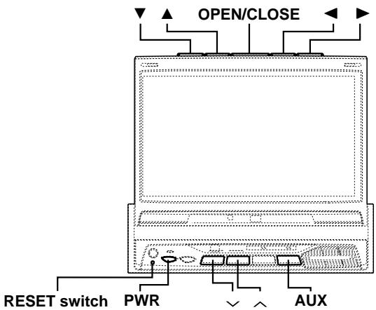
text_image
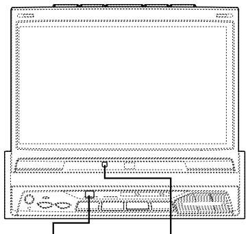
OPEN/CLOSE RESET switch PWR AUXUsing Face Cover
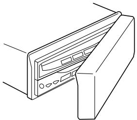
An anti-theft face cover is provided with the TME-M790.
Put the face cover onto the TME-M790 when you leave the vehicle.
Be sure to remove the anti-theft face cover when you drive.
natural_image
Line drawing of a computer monitor with ports and cables (no text or symbols)Initial System Start-up
Immediately after installing or applying power to the unit, it should be initialized.
1 At the lower left corner of the screen front panel, there is a small button. Using a pencil or other pointed object, press this RESET switch to complete the initialization procedure.

Raising the Monitor
NOTE
The TME-M790 is a precision device. With careful handling, its performance can be maintained at a high level for a long time.
1 Press the OPEN/CLOSE button.
The unit beeps 3 times and raises the monitor automatically.
NOTES
- If the monitor touches an obstacle while it is being raised, the unit will stop raising the monitor immediately. Should this occur, remove the obstacle and press the OPEN/CLOSE button again to raise the monitor.
- When the movable monitor is opened, do not place any object on the monitor and be careful not to bump or apply any pressure to the monitor while it is open. This can cause damage to the mechanism.
- Under low ambient temperature conditions, the display may be dark for a short period of time immediately after the power is turned on. Once the LCD has warmed up, the display will return to normal.
- For your safety, some operation of the unit cannot be performed while the vehicle is in motion. In this case, first stop the vehicle and engage the parking brake, then perform the operation.
Lowering the Monitor
NOTE
The TME-M790 is a precision device. With careful handling, its performance can be maintained at a high level for a long time.
1 Press the OPEN/CLOSE button.
The unit will beep 3 times and lower the monitor automatically.
NOTE
If the monitor touches an obstacle while it is being lowered, the unit will stop lowering the monitor immediately.
Should this occur, remove the obstacle and press the OPEN/CLOSE button again to lower the monitor.
Turning Power On or Off
1 Press the PWR (Power) button to turn on the unit. The opening screen appears automatically.
2 Press the PWR (Power) button again to turn off the unit.
NOTES
- The TME-M790 draws minimal current even when its power switch is turned off. If the switched power (ignition) lead of the TME-M790 is connected directly to the positive (+) post of the vehicle's battery, the battery may be discharged. If this lead is unswitched, it must be disconnected from the battery post should the vehicle be left unused for an extended period of time.
An SPST (Single-Pole, Single-Throw) switch (sold separately) can be added to simplify this procedure. Then, you can simply place it in the OFF position when you leave the vehicle. Turn the SPST switch back ON before using the TME-M790. For connecting the SPST switch, refer to the Installation. - Some operation of the unit cannot be performed while the vehicle is in motion. In this case, be sure to first stop your vehicle and apply the parking brake, then perform the operation.
- After turning the system off, a slight ghost of the image will remain temporarily. This is an effect peculiar to LCD technology and is normal.
- Under cold temperature conditions, the screen may lose contrast temporarily. After a short warm-up period, it will return to normal.
Selecting the Monitor Opening Angle
The monitor opening angle can be set in 2 positions.
1 Press and hold the OPEN/CLOSE button for at least 2 seconds while the monitor is being raised. Each press changes the monitor angle back or forth.
NOTE
When the OPEN/CLOSE button is pressed and held for at least 2 seconds when the neck angle is adjusted, the neck angle adjustment is canceled. After doing this, adjust the display in the front/rear direction.
Adjusting the Monitor Viewing Angle
Adjust the monitor's angle for better visibility.
1 While viewing the screen that is shown press the ▼ or ▲ button to adjust the display to the ideal viewing angle. The display viewing angle can be adjusted between 40 and 105 degrees.
2 Press the ◀ or ▶ button to adjust the right-left viewing angle. It is possible to adjust the display viewing angle up to 15 degrees to the left or right.
Press and hold the OPEN/CLOSE button for at least 2 seconds to cancel the neck angle adjustment.
NOTES
- The angle changes continuously if the ▼ and ▲ buttons or the ◀ and ▶ buttons are held down.
- If there are any obstructions to the monitor when adjusting the angle, first remove the obstruction and then readjust the angle.
- The screen color will vary when viewed at certain angles. Adjust the screen angle for the best viewing position.
- If the voltage of the vehicle's battery power is low, the screen may blink when the screen angle is changed. This is normal and not a malfunction.
- The adjusted angle is stored in the memory.
Adjusting the Volume
1 Press the √ or ∧ button to adjust the volume.
NOTE
The volume changes continuously if the ∨ or ∧ button is held down.
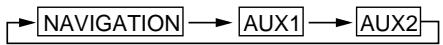
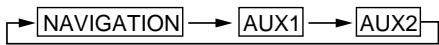
Switching the Source
1 Press the AUX button. Each press of the button will cycle through the modes as follows:
Basic Operations
text_image
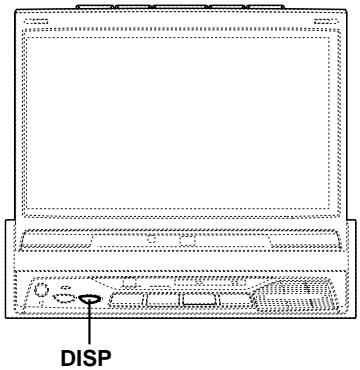
DISPSwitching Display Modes
Viewing the switching display modes
To watch a video source, your vehicle must be parked with the ignition key in the ACC or ON position. To do this, follow the procedure below.
- Push the foot brake to bring your vehicle to a complete stop at a safe location. Engage the parking brake.
- Keep pushing the foot brake and release the parking brake once then engage it again.
- While the parking brake is being engaged the second time, release the foot brake.
NOTE
For automatic transmission vehicles, place the transmission lever in the Park position.
The video lock-out system is now disabled. Unless ignition is turned OFF, this mode can be reactivated by simply engaging the parking brake, without performing the entire procedure above (1 through 3). If the ignition is turned OFF position, you must perform the entire procedure above.
NOTE
Trying to access the switching display modes while driving will display the warning - PICTURE OFF FOR YOUR SAFETY.
1 Press and hold the DISP button for at least 2 seconds. Each press changes the display modes as follows:
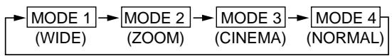
flowchart
graph LR
    A["MODE 1 (WIDE)"] --> B["MODE 2 (ZOOM)"]
    B --> C["MODE 3 (CINEMA)"]
    C --> D["MODE 4 (NORMAL)"]
natural_image
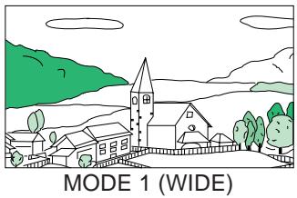
Illustration of a village landscape with houses, trees, and hills under a cloudy sky (no text or symbols)Stretches the normal image evenly in a horizontal direction so that it is displayed on the entire screen.

natural_image
Illustration of a village scene with houses, trees, and a church under a cloudy sky (no text or symbols)Stretches the normal image evenly in a horizontal direction so that it is displayed on the entire screen. The stretching ratio increases the closer to the left or right edge of the screen.

natural_image
Simple line drawing of a village with houses, a church, and green hills under a cloudy sky (no text or symbols)MODE 3 (CINEMA)
Stretches the normal image horizontally and vertically.
The top and bottom of the screen is cut slightly to adapt it to a cinema size image with a proportion of 16:9.

natural_image
Simple line drawing of a village with houses, trees, and hills under a cloudy sky (no text or symbols)MODE 4 (NORMAL)
A normal television broadcasting (4:3) image is displayed in the center (normal image).
Other Useful Features
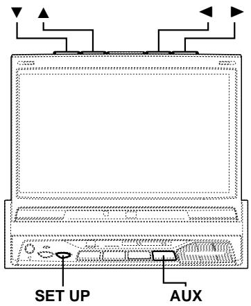
text_image
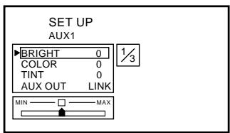
SET UP AUXAdjusting Brightness of Picture
NOTE
After carrying out the steps 1 to 3 of "Viewing the switching display modes" described on page 6, perform the operation shown below.
1 Press the SET UP button.
2 Press the ▼ or ▲ button within 10 seconds and select BRIGHT.
3 Press the ◀ or ▶ button within 10 seconds to adjust the brightness.
text_image
SET UP AUX1 BRIGHT 0 COLOR 0 TINT 0 AUX OUT LINK MIN MAX4 Press the SET UP button to finish adjustments.
NOTE
If the AUX button is pressed and held for 2 seconds or more while in the adjustment screen, the setting of the brightness, color density, and tint is reset back to its center value.
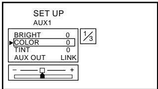
Adjusting Color Density of Picture
NOTE
After carrying out the steps 1 to 3 of "Viewing the switching display modes" described on page 6, perform the operation shown below.
1 Press the SET UP button.
2 Press the ▼ or ▲ button within 10 seconds and select COLOR.
3 Press the ◀ or ▶ button within 10 seconds to adjust the color density.
text_image
SET UP AUX1 BRIGHT 0 COLOR 0 TINT 0 AUX OUT LINK 1/34 Press the SET UP button to finish adjustments.
NOTES
- If the AUX button is pressed and held for 2 seconds or more while in the adjustment screen, the setting of the brightness, color density, and tint is reset back to its center value.
- The color density cannot be adjusted in the NAVIGATION (RGB connection) mode.
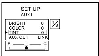
Adjusting Tint of Picture
NOTE
After carrying out the steps 1 to 3 of "Viewing the switching display modes" described on page 6, perform the operation shown below.
1 Press the SET UP button.
2 Press the ▼ or ▲ button within 10 seconds and select TINT.
3 Press the ◀ or ▶ button within 10 seconds to adjust the tint.
text_image
SET UP AUX1 BRIGHT 0 COLOR 0 TINT 0 AUX OUT LINK R G4 Press the SET UP button to finish adjustments.
NOTES
- If the AUX button is pressed and held for 2 seconds or more while in the adjustment screen, the setting of the brightness, color density, and tint is reset back to its center value.
- The tint cannot be adjusted in the NAVIGATION (RGB connection) mode.
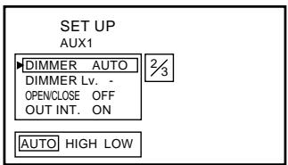
Setting the Brightness of the Backlight
It is possible to change the brightness of the LCD panel's backlighting to more closely conform to the vehicle's interior lighting. This makes the screen easier to view.
NOTE
After carrying out the steps 1 to 3 of "Viewing the switching display modes" described on page 6, perform the operation shown below.
1 Press the SET UP button.
2 Press the ▼ or ▲ button within 10 seconds and select DIMMER.
3 Press the ◀ or ▶ button within 10 seconds to set the value.
AUTO:
Automatic adjustment of the screen brightness in conformity with vehicle interior brightness.
HIGH:
Maximum screen brightness.
LOW:
The preset screen brightness that was set when adjusting the minimum backlight level.
text_image
SET UP AUX1 DIMMER AUTO DIMMER Lv. - OPENCLOSE OFF OUT INT. ON AUTO HIGH LOW 2/34 Press the SET UP button to finish adjustments.
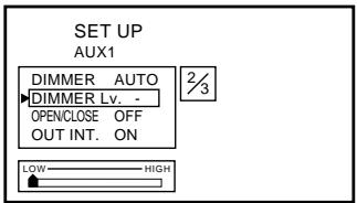
Adjusting the Lowest Level of the Backlight
It is possible with this equipment to adjust the minimum brightness level for backlighting (LOW). This is useful, for matching the screen brightness to the dashboard for driving at night. This setting is recalled with the AUTO setting corresponding to the vehicle's interior lighting.
NOTE
After carrying out the steps 1 to 3 of "Viewing the switching display modes" described on page 6, perform the operation shown below.
1 Press the SET UP button.
2 Press the ▼ or ▲ button within 10 seconds and select DIMMER Lv.
3 Press the ◀ or ▶ button within 10 seconds to set the value.
text_image
SET UP AUX1 DIMMER AUTO DIMMER Lv. - OPENCLOSE OFF OUT INT. ON 2/3 LOW HIGH4 Press the SET UP button to finish adjustments.
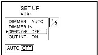
Setting Automatic Opening/ Closing of Monitor
Simply turn the ignition key to ACC ON or OFF to automatically open or close the TV display.
NOTE
After carrying out the steps 1 to 3 of "Viewing the switching display modes" described on page 6, perform the operation shown below.
1 Press the SET UP button.
2 Press the ▼ or ▲ button within 10 seconds to select OPEN/CLOSE.
3 Press the ◀ or ▶ button within 10 seconds to set the value.
AUTO:
Automatic opening or closing of the display in depending upon whether the ignition switch is ON or OFF.
OFF:
Manual opening or closing of the display.
text_image
SET UP AUX1 DIMMER AUTO DIMMER Lv. - OPENCLOSE OFF OUT INT. ON AUTO OFF4 Press the SET UP button to finish adjustments.
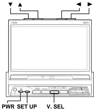
Other Useful Features
text_image
PWR SET UP V. SELSelecting Rear Monitor
This unit has controls to switch the video and audio to a rear monitor if another (rear) monitor is connected.
NOTE
After carrying out the steps 1 to 3 of "Viewing the switching display modes" described on page 6, perform the operation shown below.
1 Press the SET UP button.
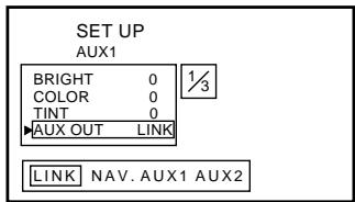
2 Press the ▼ or ▲ button within 10 seconds and select AUX OUT.
3 Press the ◀ or ▶ button within 10 seconds to carry out selection.
LINK:
Output the video/audio portion shown on the main monitor, to the rear monitor.
NAV.:
Output the navigation video/audio to the rear monitor. (Only when navigation unit is connected).
AUX 1:
Output the AUX 1 video/audio to the rear monitor.
AUX 2:
Output the AUX 2 video/audio to the rear monitor.
text_image
SET UP AUX1 BRIGHT 0 1/3 COLOR 0 TINT 0 ▶AUX OUT LINK LINK NAV. AUX1 AUX24 Press the SET UP button to finish adjustments.
Setting the External Device Interrupt Mode
When used in conjunction with an Ai interception box (KCA-801B), the sound of a TV or an external input sound can be intercepted to an Alpine head unit. This function may not work with some combinations of products. For details, refer to the KCA-801B's operating instructions.
NOTE
After carrying out the steps 1 to 3 of "Viewing the switching display modes" described on page 6, perform the operation shown below.
1 Press the SET UP button.
2 Press the ▼ or ▲ button within 10 seconds and select OUT INT.
3 Press the ◀ or ▶ button within 10 seconds to turn ON.
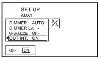
text_image
SET UP AUX1 DIMMER AUTO DIMMER Lv. - OPENCLOSE OFF OUT INT. ON OFF ON4 Press the SET UP button to finish adjustments.
Switching the Opening Screen
You can change the opening screen to your liking.
NOTE
After carrying out the steps 1 to 3 of "Viewing the switching display modes" described on page 6, perform the operation shown below.
1 Press the SET UP button.
2 Press the ▼ or ▲ button within 10 seconds and select H.U. IND.
3 Press the ◀ or ▶ button within 10 seconds to set the selection.
ON:
Special opening screen.
This setting is used when combining with the
Flagship System model.
OFF:
Normal opening screen.
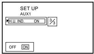
text_image
SET UP AUX1 H.U. IND. ON 3/3 OFF ON4 Press the SET UP button to finish adjustments.
Turning Sound Guide Function On or Off
This function will give audible feedback with varying tones depending upon the button pressed.
1 Press and hold the PWR button for 2 seconds with the power OFF and turn the Sound Guide ON or OFF.
Switching the Video Screen
It is possible to change the video source for display while retaining the present audio portion.
1 Press the V.SEL button.
2 To release press and hold the V.SEL button for 2 seconds.
Using the External Input Terminal
It is possible to enjoy video and sound from a video camera, etc. by simply connecting it with an optional adapter cable.

text_image
Video camera, etc. Main unit VIDEO OUT L=48000T=8 Optional adapter cable (RCA pin plugs [yellow, red, white] 3.5ø miniplugs).NOTE
With the above connections, video source switching and settings and adjustments at adjustment screens are not possible.
Other Useful Features
RUE-4165
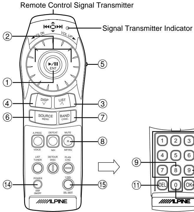
text_image
Remote Control Signal Transmitter Signal Transmitter Indicator ② VOL UP ⑤ ① ④ ⑥ ③ ⑦ ⑧ SOURCE MENU BAND CANC. A PROC DEFEAT MUTE VOICE NH MP/RG LIST TUNER DETOUR DISC PLAN CHG POWER VSEL DSP ON/OFF DEL DEST. 14 15 ALPINE 1 2 3 4 5 6 7 8 9 DEL 0 OK ALPINE(When the flip cover is open)
Remote Control Sensor
natural_image
Line drawing of a laptop computer front panel with control buttons and indicator lights (no text or symbols)Remote Sensor
(when the display is stowed away)
Remote Sensor
(when the display is raised)
- Point the remote control transmitter toward the remote sensor on the TME-M790 and use the remote control within 2 meters from the TME-M790.
Operating with the Remote Control Unit (RUE-4165 Sold Separately)
| Button No. | RUE-4165 | |
| 1 |  | Select the item on the adjustment screen.Moves to the left or right when you press on the ← or → side.Moves up and down when you press on the ↑ or ↓ side. |
| 2 |  | Volume increases when turned in a clockwise direction.Volume decreases when turned in a counter-clockwise direction. |
| 3 |  | Volume increases.Changes continuously when held down. |
| 4 |  | Volume decreases.Changes continuously when held down. |
| 5 |  | When operating this equipment, change to the NAVI side. |
| 6 |  | Displays the adjustment screen. |
| 7 |  | Terminates the adjustment screen. |
| 8 | [actc] | The display mode changes. |
| 9 | [0774] | Display angle adjustment (left).Changes continuously when held down. |
| Button No. | RUE-4165 | |
| 10 | [###] | Display angle adjustment (right).Changes continuously when held down. |
| 11 | [###] | Display angle adjustment (down).Changes continuously when held down. |
| 12 | [###] | Display angle adjustment (up).Changes continuously when held down. |
| 13 | [###] | When pressed less than 2 seconds:OPEN/CLOSE of display.When pressed at least 2 seconds:Display slides forward and backward. |
| 14 | [###] | Power ON/OFF. |
| 15 | [###] | Switch the video source. |
| [###] | When switch 5 is set to the AUDIO side. |
Information
In Case of Difficulty
If you encounter a problem, please review the items in the following checklist. This guide will help you isolate the problem if the unit is at fault. Otherwise, make sure the rest of your system is properly connected or consult your authorized Alpine dealer.
No function or display.
- Car's ignition is off.
- Turn the ignition on.
- No fuse or blown fuse.
- Check the cause and replace the fuse.
- Incorrect connections.
- Check connection and remedy.
• Vehicle's battery is weak. - Check the voltage of vehicle's battery.
Unclear picture display.
- Fluorescent tube is exhausted.
- Replace the fluorescent tube.*
No picture display.
- Brightness control is set for minimum brightness control.
- Adjust the brightness.
- Incorrect setting of the VCR mode.
- Switch to the correct mode.
- Protective circuit is on because of high temperature.
- Wait until the temperature inside the vehicle comes down to the operating temperature range (45°C).
- Incorrect or open connection with the Monitor, AV interface unit.
- Check the connection and remedy.
Picture color is poor.
- Brightness/Color/Tint control are not set to the proper positions.
- Check each control.
Spots or dotted lines/stripes appear.
- Caused by neon signs, high-voltage power lines, CB transmitter, other vehicle's ignition plugs, etc.
- Change the location of your vehicle.
The display angle cannot be adjusted or the adjustment screen does not appear.
- Mechanism error.
- Press the OPEN/CLOSE button to stow away the display, and raise the display again.
* The fluorescent tube replacement is not free of charge even within the warranty period, for the tube is an article of consumption.
Specifications
MONITOR SECTION
| Screen Size | 7.0" |
| LCD Type | Transparent type TN LCD |
| Operation System | TFT active matrix |
| Number of Picture Elements | 336,960 pcs. (1,440 x 234) |
| Effective Number of Picture Elements | 99.99% or more |
| Illumination System | Cold cathode fluorescent tube |
AV-INTERFACE UNIT SECTION
| S/N Ratio | |
| Video | 45dB |
| Audio | 55dB |
| Input Level | |
| Video | 1 Vp-p (75Ω UNBALANCED) |
| Audio | 500mV (RMS) |
| Output Level | |
| Video | 1 Vp-p (75Ω UNBALANCED) |
| Audio | 500mV (RMS) |
GENERAL
| Power Requirement | 14.4V DC (11-15 V allowable) |
| Operating temperature | +32°F to +113°(0°C to +45°C) |
| Weight | |
| (Monitor Section) | 2.0 kg (4 lbs. 7 oz) |
| (AV-Interface Unit Section) | 0.2 kg (7 oz) |
CHASSIS SIZE (Monitor section)
| Width | 178 mm (7") |
| Height | 50 mm (2") |
| Depth | 165 mm (6-1/2") |
CHASSIS SIZE
(AV-Interface Unit section)
| Width | 106.6 mm (4-1/4") |
| Height | 32 mm (1-1/4") |
| Depth | 67.8 mm (2-11/16") |
NOTES
- Due to continuous product improvement, specifications and design are subject to change without notice.
- The LCD panel is manufactured using an extremely high precision manufacturing technology. Its effective pixel ratio is over 99.99% . This means that there is a possibility that 0.01% of the pixels could be either always ON or OFF.
Installation and Connections
Before installing or connecting the unit, please read the following and pages 2 and 3 of this manual thoroughly for proper use.

Warning
MAKE THE CORRECT CONNECTIONS.
Failure to make the proper connections may result in fire or product damage.
USE ONLY IN CARS WITH A 12 VOLT NEGATIVE GROUND.
(Check with your dealer if you are not sure.) Failure to do so may result in fire, etc.
BEFORE WIRING, DISCONNECT THE CABLE FROM THE NEGATIVE BATTERY TERMINAL.
Failure to do so may result in electric shock or injury due to electrical shorts.
DO NOT ALLOW CABLES TO BECOME ENTANGLED IN SURROUNDING OBJECTS.
Arrange wiring and cables in compliance with the manual to prevent obstructions when driving. Cables or wiring that obstruct or hang up on places such as the steering wheel, gear lever, brake pedals, etc. can be extremely hazardous.
DO NOT SPLICE INTO ELECTRICAL CABLES.
Never cut away cable insulation to supply power to other equipment. Doing so will exceed the current carrying capacity of the wire and result in fire or electric shock.
DO NOT USE BOLTS OR NUTS IN THE BRAKE OR STEERING SYSTEMS TO MAKE GROUND CONNECTIONS.
Bolts or nuts used for the brake or steering systems (or any other safety-related system), or tanks should NEVER be used for installations or ground connections. Using such parts could disable control of the vehicle and cause fire etc.
KEEP SMALL OBJECTS SUCH AS BATTERY OUT OF THE REACH OF CHILDREN.
Swallowing them may result in serious injury. If swallowed, consult a physician immediately.
DO NOT INSTALL IN LOCATIONS WHICH MIGHT HINDER VEHICLE OPERATION, SUCH AS THE STEERING WHEEL OR GEARSHIFT.
Doing so may obstruct forward vision or hamper movement etc. and results in serious accident.

Caution
HAVE THE WIRING AND INSTALLATION DONE BY EXPERTS.
The wiring and installation of this unit requires special technical skill and experience. To ensure safety, always contact the dealer where you purchased this product to have the work done.
USE SPECIFIED ACCESSORY PARTS AND INSTALL THEM SECURELY.
Be sure to use only the specified accessory parts. Use of other than designated parts may damage this unit internally or may not securely install the unit in place. This may cause parts to become loose resulting in hazards or product failure.
ARRANGE THE WIRING SO IT IS NOT CRIMPED OR PINCHED BY A SHARP METAL EDGE.
Route the cables and wiring away from moving parts (like the seat rails) or sharp or pointed edges. This will prevent crimping and damage to the wiring. If wiring passes through a hole in metal, use a rubber grommet to prevent the wire's insulation from being cut by the metal edge of the hole.
DO NOT INSTALL IN LOCATIONS WITH HIGH MOISTURE OR DUST.
Avoid installing the unit in locations with high incidence of moisture or dust. Moisture or dust that penetrates into this unit may result in product failure.
Precautions
- Be sure to disconnect the cable from the (−) battery post before installing your TME-M790. This will reduce any chance of damage to the unit in case of a short-circuit.
- Be sure to connect the color coded leads according to the diagram. Incorrect connections may cause the unit to malfunction or damage the vehicle's electrical system.
- When making connections to the car's electrical system, be aware of the factory installed components (e.g. on-board computer). Do not tap into these leads to provide power for this unit. When connecting the TME-M790 to the fuse box, make sure the fuse for the intended circuit of the TME-M790 has the appropriate amperage. Failure to do so may result in damage to the unit and/or the vehicle. When in doubt, consult your ALPINE dealer.
- The TME-M790 uses female RCA-type jacks for connection to other units (e.g. amplifier) having RCA connectors. You may need an adaptor to connect other units. If so, please contact your authorized ALPINE dealer for assistance.
- The Display must be completely retracted in the casing when installing. If it is not, problems may occur.
- When installing in automobiles, make sure the Display can open/close without coming in contact with the shift lever.
IMPORTANT
Please record the serial number of your unit in the space provided below and keep it as a permanent record. The serial number plate is located on the bottom of the unit.
SERIAL NUMBER: ____ INSTALLATION DATE: ____ INSTALLATION TECHNICIAN: ____ PLACE OF PURCHASE: ____
Installation and Connections
Installation
Installing the Monitor
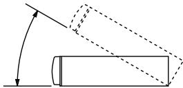
- Place of installation
Before determining the position of installation, check that the display will not hamper gear shifting when it is opened and closed in that position.
natural_image
Simple line drawing of a cylinder rolling down an inclined plane with an arrow indicating direction (no text or symbols)NOTE
Install at an angle of within 30 degrees from the horizontal.
1
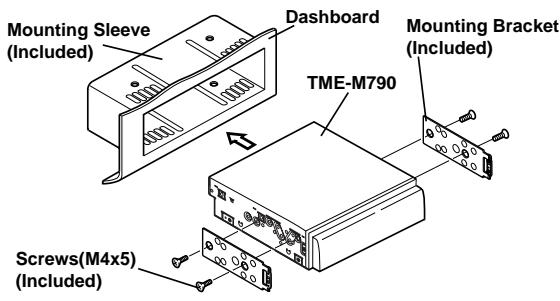
text_image
Mounting Sleeve (Included) Dashboard TME-M790 Mounting Bracket (Included) Screws(M4x5) (Included)Slide mounting sleeve from main unit (see Removal Procedure below). Slide the mounting sleeve into the dashboard. Install the supplied bracket to the monitor.
2
text_image
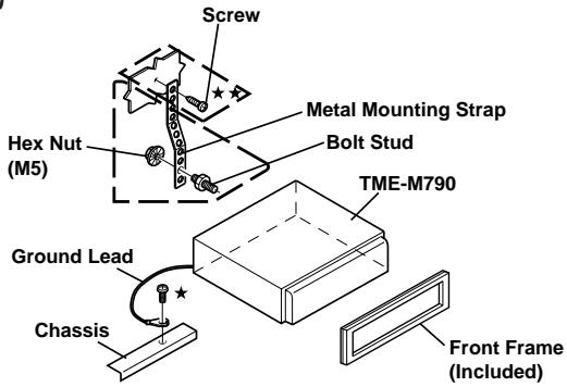
Screw Hex Nut (M5) Metal Mounting Strap Bolt Stud TME-M790 Ground Lead Chassis Front Frame (Included)Reinforce the monitor with the metal mounting strap (not supplied). Secure the ground lead of the unit to a clean metal spot using a screw ( ) already attached to the vehicle's chassis.
NOTE
For the screw marked ★★, use an appropriate screw for the chosen mounting location.
3
text_image
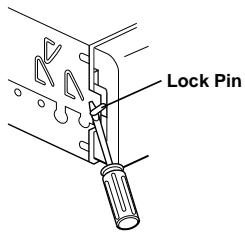
Lock PinSlide the TME-M790 into the dashboard. When the unit is in place, make sure the locking pins are fully seated in the down position. This can be done by pressing firmly in on the unit while pushing the locking pin down with a small screwdriver. This ensures that the unit is properly locked and will not accidentally come out from the dashboard. Install the Supplied Front Frame.
Removal
1 Use a small screwdriver (or similar tool) to push the locking pins to the "up" position (see above drawing). As each pin is unlocked, gently pull out on the unit to make sure it does not re-lock before unlocking the second pin.
2 Pull the unit out, keeping it unlocked as you do so.
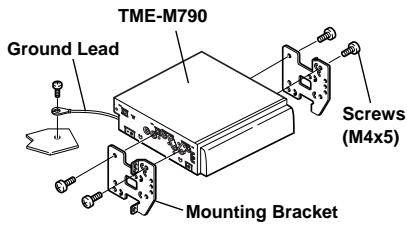
To install using the vehicle's genuine bracket
text_image
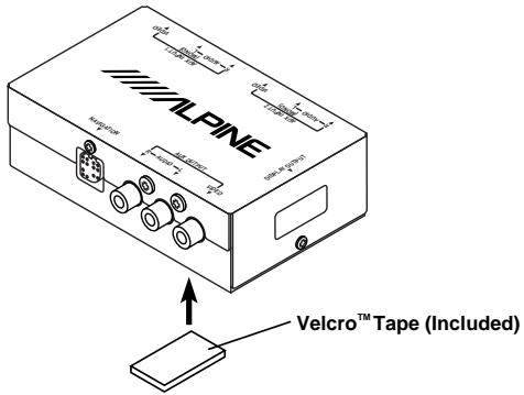
TME-M790 Ground Lead Screws (M4x5) Mounting BracketAttaching the AV-Interface Unit
When attaching with Velcro™ Tape, be sure to choose a level location.
Do not attach in a location where the AV-Interface unit is upside down.
Attach the AV-Interface Unit.
Attach the Velcro™ Tape included with the AV-Interface Unit and secure the unit under the passenger seat, for example.
text_image
ALPINE Velcro™ Tape (Included)Foot Brake Lead/Parking Brake Lead Connection
If necessary, use a pinch connector to connect the foot brake lead, parking brake lead, etc.
1
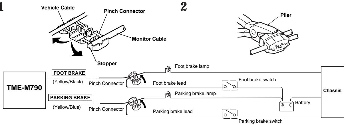
flowchart
graph LR
    A["Vehicle Cable"] --> B["Pinch Connector"]
    B --> C["Monitor Cable"]
    C --> D["Stopper"]
    D --> E["Plier"]
    F["TME-M790"] --> G["FOOT BRAKE (Yellow/Black)"]
    F --> H["PARKING BRAKE (Yellow/Blue)"]
    G --> I["Pinch Connector"]
    H --> J["Pinch Connector"]
    I --> K["Foot brake lead"]
    J --> L["Foot brake lead"]
    K --> M["Foot brake lamp"]
    L --> N["Parking brake lamp"]
    M --> O["Foot brake switch"]
    N --> P["Parking brake switch"]
    O --> Q["Battery"]
    P --> Q
    Q --> R["Chassis"]
Connection Diagram of SPST Switch (Sold Separately)
(If the ACC power supply is not available)
flowchart
graph LR
    A["TME-M790 (Monitor)"] --> B["IGNITION"]
    A --> C["BATTERY"]
    B --> D["SPST SW (Optional)"]
    C --> D
    D --> E["Battery"]
    style A fill:#f9f,stroke:#333
    style B fill:#ccf,stroke:#333
    style C fill:#ccf,stroke:#333
    style D fill:#cfc,stroke:#333
NOTE
If your vehicle has no ACC power supply, add an SPST (Single-Pole, Single-Throw) switch (sold separately). If the switched power (ignition) lead of the TME-M790 is connected directly to the positive (+) post of the vehicle's battery, the TME-M790 draws some current (several hundred milliamperes) even when its switch is placed in the OFF position and the battery may be discharged.
Installation and Connections
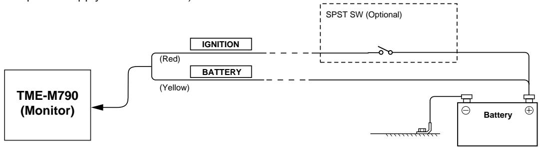
Connections
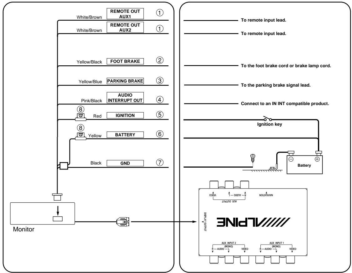
flowchart
graph TD
    A["Monitor"] --> B["White/Brown"]
    A --> C["Yellow/Black"]
    A --> D["Yellow/Blue"]
    A --> E["Pink/Black"]
    A --> F["Red"]
    A --> G["Yellow"]
    A --> H["Black"]
    B --> I["REMOTE OUT AUX1"]
    C --> J["REMOTE OUT AUX2"]
    D --> K["FOOT BRAKE"]
    E --> L["AUDIO INTERRUPT OUT"]
    F --> M["IGNITION"]
    G --> N["BATTERY"]
    H --> O["GND"]
    I --> P["To remote input lead."]
    J --> Q["To remote input lead."]
    K --> R["To the foot brake cord or brake lamp cord."]
    L --> S["To the parking brake signal lead."]
    M --> T["Connect to an IN INT compatible product."]
    N --> U["Ignition key"]
    O --> V["Battery"]
    U --> W["POWER INPUT 2 (MONO) R-AUDIO-L VIDEO"]
    V --> X["AUX INPUT 1 (MONO) R-AUDIO-L VIDEO"]
    W --> Y["OUTPUT INPUT 3 MAX OUTPUT"]
    X --> Z["OUTPUT INPUT 4 MAX OUTPUT"]
① Remote Control Output Lead (White/Brown)
Connect this lead to the remote control input lead. This lead outputs the controlling signals from the remote control.
② Foot Brake Lead (Yellow/Black)
Connect to the vehicle's foot brake lead or brake lamp lead.
③ Parking Brake Lead (Yellow/Blue)
Connect this lead to the power supply side of the parking brake switch to transmit the parking brake status signals to the TME-M790.
④ Audio Interrupt Out Lead (Pink/Black)
⑤ Switched Power Lead (Ignition) (Red)
Connect this lead to an open terminal on the vehicle's fuse box or another unused power source which provides (+) 12V only when the ignition is turned on or in the accessory position.
⑥ Battery Lead (Yellow)
Connect this lead to the positive (+) post of the vehicle's battery.
⑦ Ground Lead (Black)
Connect this lead to a good chassis ground on the vehicle. Make sure the connection is made to bare metal and is securely fastened using the sheet metal screw provided.
⑧ Fuse Holder (5A)
To prevent external noise from entering the audio system.
- Locate the unit and route the leads at least 10cm away from the car harness.
- Keep the battery power leads as far away from other leads as possible.
- Connect the ground lead securely to a bare metal spot (remove the coating if necessary) of the car chassis.
- If you add an optional noise suppressor, connect it as far away from the unit as possible. Your Alpine dealer carries various Alpine noise suppressors, contact them for further information.
- Your Alpine dealer knows best about noise prevention measures so consult your dealer for further information.
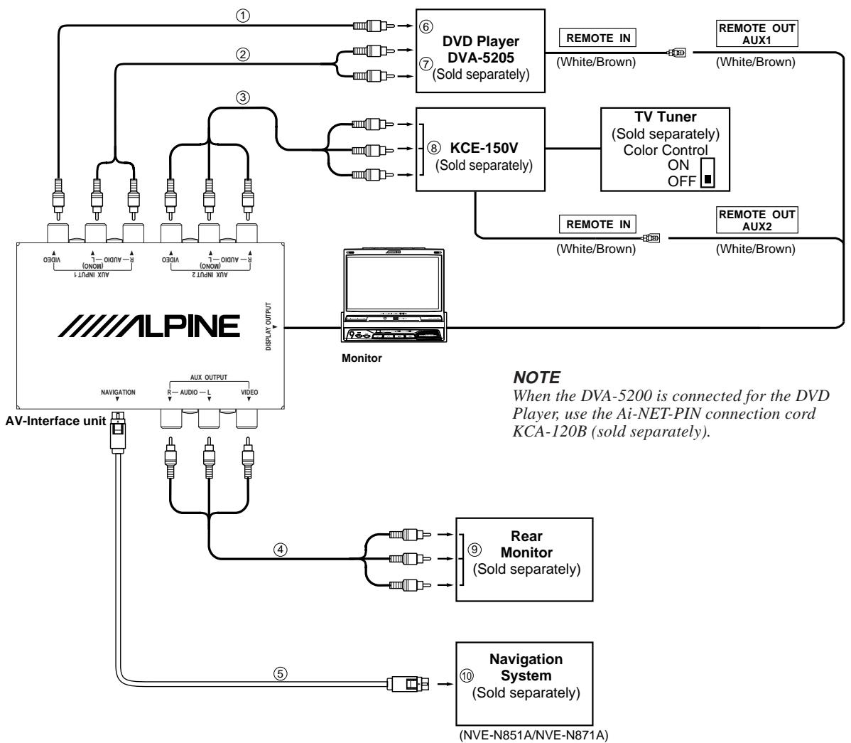
flowchart
graph TD
    A["ALPINE"] -->|① AV-Interface unit| B["Monitor"]
    A -->|② AV-Interface unit| C["DVD Player DVA-5205 (Sold separately)"]
    A -->|③ AV-Interface unit| D["KCE-150V (Sold separately)"]
    A -->|④ AV-Interface unit| E["Rear Monitor (Sold separately)"]
    A -->|⑤ AV-Interface unit| F["Navigation System (Sold separately)"]
    B --> G["TV Tuner (Sold separately) Color Control ON OFF"]
    C --> H["Remote IN (White/Brown)"]
    C --> I["Remote OUT AUX1 (White/Brown)"]
    D --> J["Remote IN (White/Brown)"]
    D --> K["Remote OUT AUX2 (White/Brown)"]
    E --> L["Note: When the DVA-5200 is connected for the DVD Player, use the Ai-NET-PIN connection cord KCA-120B (sold separately)."]
    F --> L
① RCA Extension Cable (Included with DVD Player)
② RCA Extension Cable (Option)
③ RCA Extension Cable (Included with KCE-150V)
④ RCA Extension Cable (Option)
⑤ RGB Cable (Navigation NVE-N851A: Included, Navigation NVE-N871A: Sold separately)
⑥ Video Output Connector
Connect the AUX INPUT 1, Video Input Terminal on the TME-M790 to the Video Output Connector on the DVD player.
⑦ Audio Output Connector
Connect the AUX INPUT 1, Audio Input Terminal on the TME-M790 to the Audio Output Connector (L/R) on the DVD player.
⑧ Video Output Terminal
Connect the AUX INPUT 2 Terminal on the TME-M790 to the Video Output Terminal.
⑨ AUX Input Terminal
Connect the AUX OUTPUT Terminal on the TME-M790 to the AUX Input Terminal.
⑩ RGB Output Connector
Connect the NAVIGATION RGB Connector on the TME-M790 to the RGB Output Connector on the navigation system.
NOTES
- When this product is used in combination with a separately sold Ai-NET-PIN connection cord (KCA-121B), the sound can be output to a head unit equipped with an external input. For details, refer to the head unit's operating instructions.
- When the NVA-N751AS is connected for the Navigation System, use the RGB conversion cable KWE-503N (sold separately).
GARANTIE LIMITÉE
● PRODUITS COUVERT PAR LA GARANTIE
● COMMENT SE PRÉVALOIR DE LA GARANTIE
● EXCLUSIONS DE LA GARANTIE
ALPINE STIPULE EXPRESSÉMENT QU'ELLE N'EST PAS RESPONSABLE DES DOMMAGES DOMMAGES-INTÉRÊTS ET DOMMAGES INDIRECTS PROVOQUÉS PAR LE PRODUIT. LES DOMMAGES DOMMAGES-INTÉRÊTS SONT LES FRAIS DE TRANSPORT DU PRODUIT VERS UN CENTRE DE SERVICE ALPINE, LA PERTE DE TEMPS DE L'ACHETEUR ORIGINAL, LA PERTE D'UTILISATION DU PRODUIT, LES BILLETS D'AUTOBUS, LA LOCATION DE VOITURES ET TOUS LES AUTRES FRAIS LIÉS À LA GARDE DU PRODUIT.
LES DOMMAGES INDIRECTS SONT LES FRAIS DE RÉPARATION OU DE REMPLACEMENT D'AUTRES BIENS ENDOMMAGÉS SUITE AU MAUVAIS FONCTIONNEMENT DU PRODUIT.
LES RECOURS PRÉVUS PAR LES PRÉSENTES EXCLUENT ET REMPLACENT TOUTE AUTRE FORME DE RECOURS.
● LIEN ENTRE LA GARANTIE ET LA LOI
● CLAUSE APPLICABLE AU CANADA SEULEMENT
ALPINE ELECTRONICS OF AMERICA, INC. AND ALPINE OF CANADA INC. ("Alpine"), are dedicated to quality craftsmanship and are pleased to offer this Warranty. We suggest that you read it thoroughly. Should you have any questions, please contact your Dealer or Alpine at one of the telephone numbers listed below.
● PRODUCTS COVERED:
This Warranty covers Car Audio/Visual Products and Related Accessories ("the product"). Products purchased in the Canada are covered only in the Canada. Products purchased in the U.S.A. are covered only in the U.S.A.
● LENGTH OF WARRANTY:
This Warranty is in effect for one year from the date of the first consumer purchase.
● LIFETIME TAPE HEAD WARRANTY:
All Alpine Car Audio analog tape heads excluding Video tape heads are warranted for life against manufacturing defects causing failure.
● WHO IS COVERED:
This Warranty only covers the original purchaser of the product, who must reside in the United States, Puerto Rico or Canada.
● WHAT IS COVERED:
This Warranty covers defects in materials or workmanship (parts and labor) in the product.
● WHAT IS NOT COVERED:
This Warranty does not cover the following:
① Damage occurring during shipment of the product to Alpine for repair (claims must be presented to the carrier).
② Damage caused by accident, abuse, negligence, misuse, improper connections, improper operation or failure to follow instructions contained in the Owner's manual.
③ Damage caused by act of God, including without limitation, earthquake, fire, flood, storms or other acts of nature.
④ Any cost or expense related to the removal or reinstallation of the product.
⑤ Service performed by an unauthorized person, company or association.
⑥ Any product which has the serial number defaced, altered or removed.
⑦ Any product which has been adjusted, altered or modified without Alpine's consent.
⑧ Any product not distributed by Alpine within the United States, Puerto Rico or Canada.
⑨ Any product not purchased from an Authorized Alpine Dealer.
⑩ Any product that has been determined to contain an excessive amount of dust or dirt and any product that contains other contaminants including liquid or foreign objects.
● HOW TO OBTAIN WARRANTY SERVICE:
① You are responsible for delivery of the product to an Authorized Alpine Service Center or Alpine for repair and for payment of any initial shipping charges. Alpine will, at its option, repair or replace the product with a new or reconditioned product without charge. If the repairs are covered by the warranty, and if the product was shipped to an Authorized Alpine Service Center or Alpine, Alpine will pay the return shipping charges.
② You should provide a detailed description of the problem(s) for which service is required.
③ You must supply proof of your purchase of the product.
④ You must package the product securely to avoid damage during shipment.
● HOW WE LIMIT IMPLIED WARRANTIES:
ANY IMPLIED WARRANTIES INCLUDING FITNESS FOR USE AND MERCHANTABILITY ARE LIMITED IN DURATION TO THE PERIOD OF THE EXPRESS WARRANTY SET FORTH ABOVE AND NO PERSON IS AUTHORIZED TO ASSUME FOR ALPINE ANY OTHER LIABILITY IN CONNECTION WITH THE SALE OF THE PRODUCT.
- HOW WE EXCLUDE CERTAIN DAMAGES: ALPINE EXPRESSLY DISCLAIMS LIABILITY FOR INCIDENTAL AND CONSEQUENTIAL DAMAGES CAUSED BY THE PRODUCT. THE TERM "INCIDENTAL DAMAGES" REFERS TO EXPENSES OF TRANSPORTING THE PRODUCT TO THE ALPINE SERVICE CENTER, LOSS OF THE ORIGINAL PURCHASER'S TIME, LOSS OF THE USE OF THE PRODUCT, BUS FARES, CAR RENTALS OR OTHERS COSTS RELATING TO THE CARE AND CUSTODY OF THE PRODUCT. THE TERM "CONSEQUENTIAL DAMAGES" REFERS TO THE COST OF REPAIRING OR REPLACING OTHER PROPERTY WHICH IS DAMAGED WHEN THIS PRODUCT DOES NOT WORK PROPERLY. THE REMEDIES PROVIDED UNDER THIS WARRANTY ARE EXCLUSIVE AND IN LIEU OF ALL OTHERS.
● HOW STATE/PROVINCIAL LAW RELATES TO THE WARRANTY:
This Warranty gives you specific legal rights, and you may also have other rights which vary from state to state and province to province. In addition, some states/provinces do not allow limitations on how long an implied warranty lasts, and some do not allow the exclusion or limitation of incidental or consequential damages. Accordingly, limitations as to these matters contained herein may not apply to you.
● IN CANADA ONLY:
This Warranty is not valid unless your Alpine car audio product has been installed in your vehicle by an Authorized Installation Center, and this warranty stamped upon installation by the installation center.
● HOW TO CONTACT CUSTOMER SERVICE:
Should the product require service, please call the following number for your nearest Authorized Alpine Service Center.
U.S.A. 1-800-ALPINE-1 (1-800-257-4631)
CANADA 1-800-ALPINE-1 (1-800-257-4631)