NVE-N077PS - Car stereo ALPINE - Free user manual and instructions
Find the device manual for free NVE-N077PS ALPINE in PDF.

User questions about NVE-N077PS ALPINE
0 question about this device. Answer the ones you know or ask your own.
Ask a new question about this device
Download the instructions for your Car stereo in PDF format for free! Find your manual NVE-N077PS - ALPINE and take your electronic device back in hand. On this page are published all the documents necessary for the use of your device. NVE-N077PS by ALPINE.
USER MANUAL NVE-N077PS ALPINE
Suite 203, 7300 Warden Ave. Markham,
Ontario L3R 9Z6, Canada
Tel.: 1-800-ALPINE-1 (1-800-257-4631)
1-888-NAV-HELP (1-888-628-4357)
ALPINE ELECTRONICS OF AUSTRALIA PTY. LTD.
6-8 Fiveways Boulevarde Keysborough,
Victoria 3173, Australia
Tel.: (03) 9769-0000
ALPINE ELECTRONICS GmbH
Kreuzerkamp 7-11
40878 Ratingen, Germany
Tel.: 02102-45 50
13 Tanners Drive, Blakelands,
Milton Keynes MK14 5BU, U.K.
Tel.: 01908-61 15 56
ALPINE ELECTRONICS DE ESPAÑA, S.A.
Portal De Gamarra 36, Pabellón 32
01013 Vitoria (Alava)-Apdo. 133, Spain
Tel.: 34-45-283588
Designed by ALPINE Japan
Printed in Japan (Y)
68P41262Y25-O
Yamagata Printing
Co., Ltd.
2-6-34, Takashima,
Nishi-ku, Yokohama,
Kanagawa, Japan
ALPINE®
Voice Navigation System
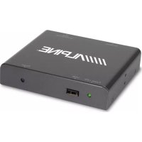
NVE-N077PS
Guide for Installation and Connections
- Please read this GUIDE FOR INSTALLATION AND CONNECTIONS FOR AUTHORIZED ALPINE DEALERS and the OWNER'S MANUAL thoroughly to familiarize yourself with each control and function. We at ALPINE hope that your new NVE-N077PS will give you many years of enjoyment.
In case of problems when installing your unit, please contact your authorized ALPINE dealer.
Points to Observe for Safe Usage
- For safe operation of this system, please read this manual carefully. We cannot be responsible for problems resulting from failure to observe the instructions in this manual.
-
Pictorial displays are used to point out safety tips to prevent harm to yourself or others and property damage. Here is what these pictorial displays mean. Knowing them is important to understand this manual.
-
Meaning of displays
| [SWCB] Warning | This symbol means important instructions. Failure to heed them can result in serious injury or death. |
 Caution Caution | This symbol means important instructions. Failure to heed them can result in injury or material property damage. |

Warning
DO NOT DISASSEMBLE OR ALTER. Doing so may result in an accident, fire or electric shock.
KEEP SMALL OBJECTS SUCH AS BATTERY OUT OF THE REACH OF CHILDREN. Swallowing them may result in serious injury. If swallowed, consult a physician immediately.
USE THE CORRECT AMPERE RATING WHEN REPLACING FUSES. Failure to do so may result in fire or electric shock.
USE ONLY IN CARS WITH A 12 VOLT NEGATIVE GROUND. (Check with your dealer if you are not sure.) Failure to do so may result in fire, etc.
BEFORE WIRING, DISCONNECT THE CABLE FROM THE NEGATIVE BATTERY TERMINAL.
Failure to do so may result in electric shock or injury due to electrical shorts.
DO NOT ALLOW CABLES TO BECOME ENTAN- GLED IN SURROUNDING OBJECTS. Arrange
wiring and cables in compliance with the manual to prevent obstructions when driving. Cables or wiring that obstruct or hang up on places such as the steering wheel, shift lever, brake pedals, etc. can be extremely hazardous.
DO NOT SPLICE INTO ELECTRICAL CABLES.
Never cut away cable insulation to supply power to other equipment. Doing so will exceed the current carrying capacity of the wire and result in fire or electric shock.
DO NOT INSTALL IN LOCATIONS WHICH MIGHT HINDER VEHICLE OPERATION, SUCH AS THE STEERING WHEEL OR SHIFT LEVER. Doing so may obstruct forward vision or hamper movement etc. and results in serious accident.
DO NOT DAMAGE PIPE OR WIRING WHEN
DRILLING HOLES. When drilling holes in the chassis for installation, take precautions so as not to contact, damage or obstruct pipes, fuel lines, tanks or electrical wiring. Failure to take such precautions may result in fire.
DO NOT USE BOLTS OR NUTS IN THE BRAKE OR STEERING SYSTEMS TO MAKE GROUND
CONNECTIONS. Bolts or nuts used for the brake or steering systems (or any other safety-related system), or tanks should NEVER be used for installations or ground connections. Using such parts could disable control of the vehicle and cause fire etc.
DO NOT INSTALL THE MONITOR NEAR THE PASSENGER SEAT AIR BAG. If the unit is not
installed correctly the air bag may not function correctly and when triggered the air bag may cause the monitor to spring upwards causing an accident and injuries.
MAKE THE CORRECT CONNECTIONS. Failure to make the proper connections may result in fire or product damage.
Caution
ARRANGE THE WIRING SO IT IS NOT CRIMPED OR PINCHED BY A SHARP METAL EDGE. Route the cables and wiring away from moving parts (like the seat rails) or sharp or pointed edges. This will prevent crimping and damage to the wiring. If wiring passes through a hole in metal, use a rubber grommet to prevent the wire's insulation from being cut by the metal edge of the hole.
HAVE THE WIRING AND INSTALLATION DONE BY EXPERTS. The wiring and installation of this unit requires special technical skill and experience. To ensure safety, always contact the dealer where you purchased this product to have the work done.
USE SPECIFIED ACCESSORY PARTS AND INSTALL THEM SECURELY. Be sure to use only the specified accessory parts. Use of other than designated parts may damage this unit internally or may not securely install the unit in place. This may cause parts to become loose resulting in hazards or product failure.
DO NOT INSTALL IN LOCATIONS WITH HIGH MOISTURE OR DUST. Avoid installing the unit in locations with high incidence of moisture or dust. Moisture or dust that penetrates into this unit may result in product failure.
Precautions
IMPORTANT
Please record the serial number of your unit in the space provided on the back cover of Owner's Manual and keep it as a permanent record. The serial number plate is located on the bottom of the unit.
- For installation of the main unit, avoid areas with a high incidence of dust or moisture. Installing the unit in such locations may result in contamination of the DVD ROM making it unreadable.
- Do not install the navigation system near a CD player that may interfere with GPS signal reception.
- The optimum locations for installing the GPS aerial are:
- on the dashboard where no metal piece (such as the defogger wire or aerial wire) is located on the windshield.
– where no metal cover is located. - Route the Speed Pulse Sensor cable away from the audio cables in order to avoid picking up noises.
Contents
PRECAUTIONS 2
- Preparation 5
- Connections 6
3-1. NVE-N077PS Wiring Diagram With CVA-1003R/TME-M750 7
3-2. NVE-N077PS Wiring Diagram With IVX-C806/IVA-C800R/IVX-M706/IVA-M700R/CVA-1006R/CVA-1005R 8
3-3. NVE-N077PS Wiring Diagram With CVA-1000R 9
3-4. NVE-N077PS Wiring Diagram With TME-M006SP/TME-M005P 10 - Mounting 11
- Confirmation 12
1. Preparation
1 Check accessory parts.
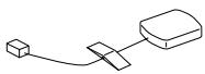
GPS aerial (5 m)
Aerial
mounting plate
Cable clamp
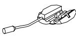
Parking brake
aux. cord
Solderless connector

Remote control

Remote control holder
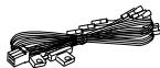
(2.5 m)
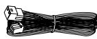
(4.5 m)

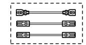
Extension cables
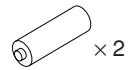
Battery (AAA)
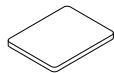
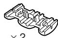
① Bracket
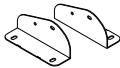
One each for left and right
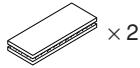
② Floor base
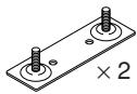
③ Screw with double washer (M5 × 8)

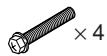
④ Hex bolt (M6 × 50)
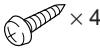
⑤ Flanged self-tapping screw (M5 × 15)

⑥ Spring washer (M6)

⑦ Flanged hex nut (M6)

⑧ Wing nut (M6)

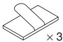
⑨ Velcro fastener
⑩ Velcro tape

⑪ Self-tapping screw (M3 × 12)
2 Prepare tools and mounting information.
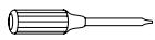
Screwdriver

Electrical tape
Pliers
Spanner
Pencil and eraser
3 Park the vehicle in a safe and level location.
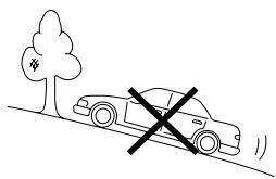
natural_image
Simple line drawing of a car on a hillside with a cross symbol indicating restriction (no text or labels)4 Apply the brake and remove the ignition key.
5 Mount the aerial on the roof.
Clean dust and oil at the mounting location and mount the aerial.

text_image
AerialNotes:
- The magnet of the aerial is very strong. Proceed cautiously to prevent any damage to the vehicle's body. Keep the magnet away from articles susceptible to magnetic fields such as credit cards, watches, etc.
- Do not paint the aerial. Reception sensitivity may be decreased.
Mounting the aerial inside the vehicle.
- Clean the mounting location.
- Put on the aerial mounting plate.
- Mount the aerial.
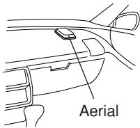
text_image
AerialNotes:
- Mount the aerial on a flat plane of the dash board or rear tray.
- Some thermal reflection type or thermal absorption type glass may interrupt high frequency waves. If reception is poor with the aerial installed inside the car, try to mount the aerial outside the car.
6 Routing the aerial cable.
- Route the cable using the provided cable clamps to take up the cable's slack.
- Use the waterproof pad when running the cable under the vehicle's rubber gasket.
- Attach the cable at several points using the remaining cable clamps.
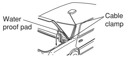
text_image
Water proof pad Cable clamp2. Connections
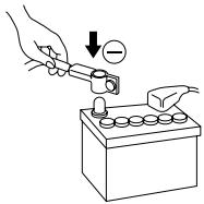
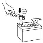
1 Disconnect the battery (−) terminal.
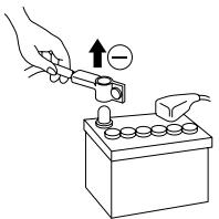
text_image
Diagram showing a hand using a tool to press a battery with an arrow indicating positive charge and negative charge.Note:
Some vehicles contain a vehicle control computer etc. in this case, contents of the computer memory may be erased when the battery (−) lead is disconnected.
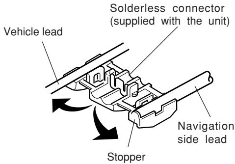
2 Cut terminal leads as required, and attach the solderless connectors to the leads.
Note:
For leads which need branching to the speed sensor, dimmer, parking brake, etc., use the solderless connectors.
Preparation
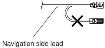
text_image
Navigation side lead1
text_image
Vehicle lead Solderless connector (supplied with the unit) Navigation side lead Stopper2
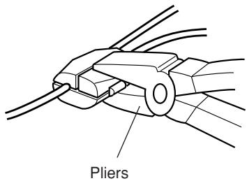
text_image
Pliers3 Connect the power lead to this unit.
Insert until a click sound is heard.
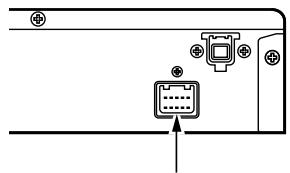
text_image
Diagram showing a device panel with an icon and an arrow pointing to it, likely indicating a status or operation.4 Wrap electrical tape around end of leads not used.
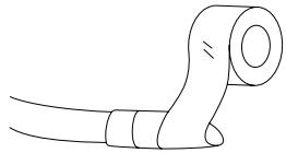
natural_image
Simple line drawing of a mechanical component with no text or symbols5 Connect the battery (−) terminal and turn the ignition key to the ACC or ON position. Check to see if operation can be performed properly. (Is the power turned on? Is the illumination turned on?)
You can check the language selection menu with the monitor. (Refer to the Owner's Manual for details.) Go to step 6 after checking is completed.
text_image
Diagram showing a hand using a tool to adjust or install a battery, with a magnified view indicating the negative charge.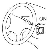
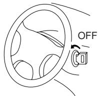
6 Turn the ignition key to the OFF position to turn off the power after completion of the check.
text_image
OFF7 Pull out the ignition key and remove the battery terminal (−) again to begin installation procedure.
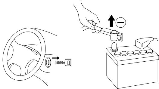
text_image
Diagram illustrating car wheel and battery electrical switch operation with labeled components3-1. NVE-N077PS Wiring Diagram With CVA-1003R/TME-M750
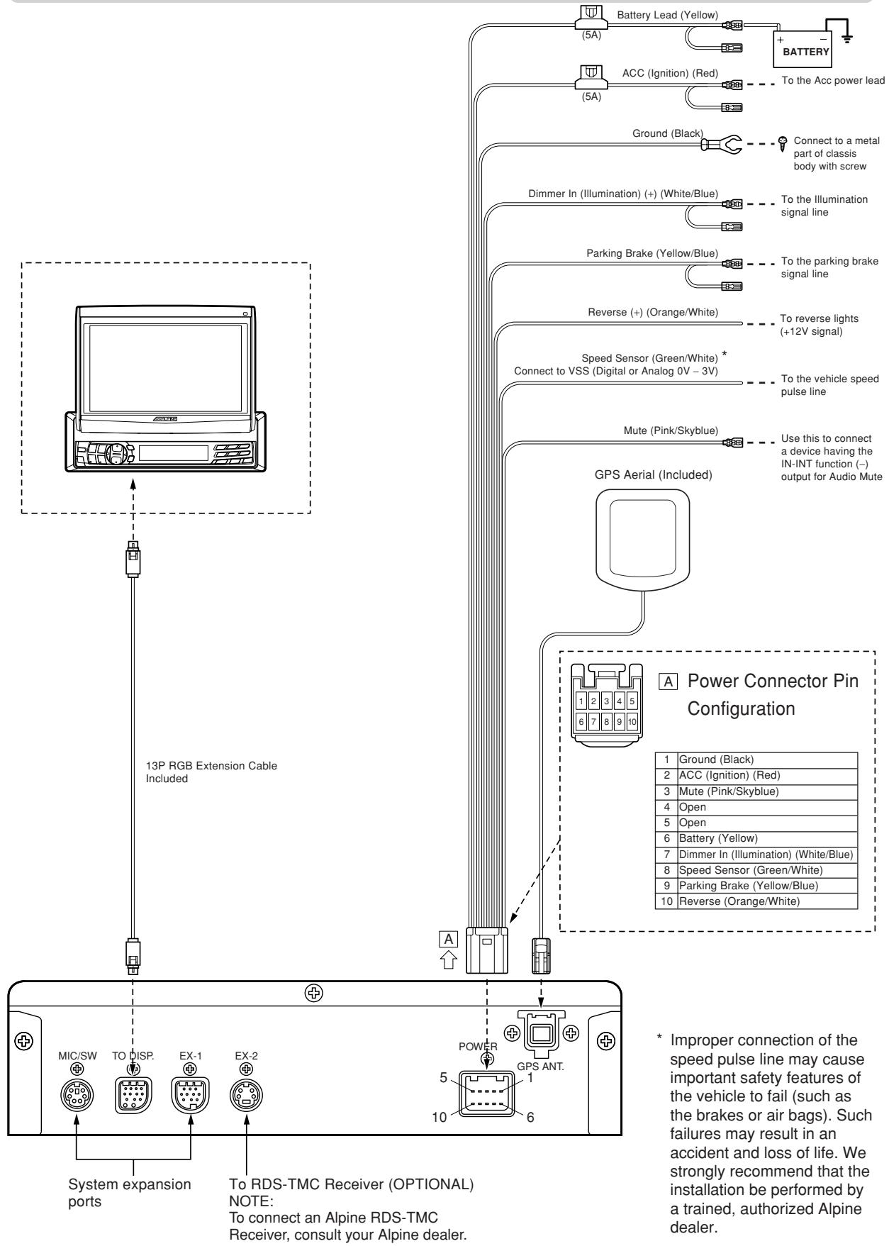
flowchart
graph TD
    A["13P RGB Extension Cable Included"] --> B["13P System expansion ports"]
    B --> C["To RDS-TMC Receiver (OPTIONAL) NOTE: To connect an Alpine RDS-TMC Receiver, consult your Alpine dealer."]
    C --> D["POWER GPS ANT. 5 10"]
    D --> E["GPS Aerial Included"]
    E --> F["Battery Lead (Yellow)"]
    E --> G["BATTERY"]
    E --> H["Ground (Black)"]
    E --> I["Dimmer In (Illumination) (+) (White/Blue)"]
    E --> J["Parking Brake (Yellow/Blue)"]
    E --> K["Reverse (+) (Orange/White)"]
    E --> L["Speed Sensor (Green/White) * Connect to VSS (Digital or Analog 0V - 3V)"]
    E --> M["Mute (Pink/Skyblue)"]
    E --> N["Use this to connect a device having the IN-INT function (-) output for Audio Mute"]
    E --> O["A Power Connector Pin Configuration"]
    style A fill:#f9f,stroke:#333
    style B fill:#ccf,stroke:#333
    style C fill:#cfc,stroke:#333
    style D fill:#fcc,stroke:#333
    style E fill:#cff,stroke:#333
    style F fill:#ffc,stroke:#333
    style G fill:#ffc,stroke:#333
    style H fill:#ffc,stroke:#333
    style I fill:#ffc,stroke:#333
    style J fill:#ffc,stroke:#333
    style K fill:#ffc,stroke:#333
    style L fill:#ffc,stroke:#333
    style M fill:#ffc,stroke:#333
    style N fill:#ffc,stroke:#333
    style O fill:#ffc,stroke:#333
3-2. NVE-N077PS Wiring Diagram With IVX-C806/IVA-C800R/IVX-M706/IVA-M700R/CVA-1006R/CVA-1005R
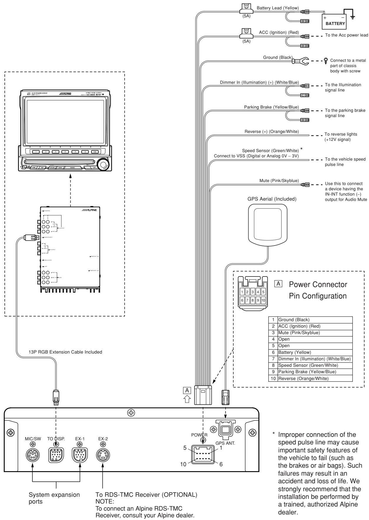
flowchart
graph TD
    A["ALPINE"] --> B["13P RGB Extension Cable Included"]
    B --> C["System expansion ports"]
    C --> D["To RDS-TMC Receiver (OPTIONAL) NOTE: To connect an Alpine RDS-TMC Receiver, consult your Alpine dealer."]
    D --> E["POWER GPS ANT. 5 10 6"]
    E --> F["GPS Aerial Included"]
    F --> G["Power Connector Pin Configuration"]
    G --> H["Battery Lead (Yellow)"]
    G --> I["ACC Ignition (Red)"]
    G --> J["Ground (Black)"]
    G --> K["Dimmer In (Illumination) (+) (White/Blue)"]
    G --> L["Parking Brake (Yellow/Blue)"]
    G --> M["Reverse (+) (Orange/White)"]
    G --> N["Speed Sensor (Green/White) * Connect to VSS (Digital or Analog 0V - 3V)"]
    G --> O["Mute (Pink/Skyblue)"]
    G --> P["Use this to connect a device having the IN-INT function (-) output for Audio Mute"]
    H --> Q["BATTERY"]
    I --> R["To the Acc power lead"]
    J --> S["To the Illumination signal line"]
    K --> T["To the parking brake signal line"]
    L --> U["To reverse lights (+12V signal)"]
    M --> V["To the vehicle speed pulse line"]
    N --> W["Use this to connect a device having the IN-INT function (-) output for Audio Mute"]
    O --> X["Power Connector Pin Configuration"]
    P --> Y["Power Connector Pin Configuration"]
3-3. NVE-N077PS Wiring Diagram With CVA-1000R
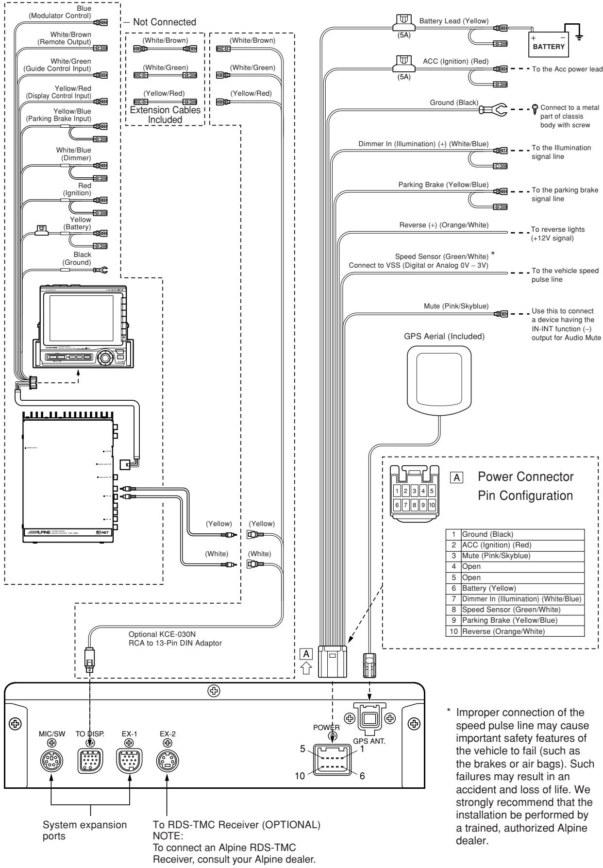
flowchart
graph TD
    A["Blue (Modulator Control)"] --> B["White/Brown (Remote Output)"]
    A --> C["White/Green (Guide Control Input)"]
    A --> D["Yellow/Red (Display Control Input)"]
    A --> E["Yellow/Blue (Parking Brake Input)"]
    A --> F["White/Blue (Dimmer)"]
    A --> G["Red (Ignition)"]
    A --> H["Yellow (Battery)"]
    A --> I["Black (Ground)"]
    J["Not Connected"] --> K["(White/Brown)"]
    J --> L["(White/Green)"]
    J --> M["(Yellow/Red)"]
    J --> N["(Yellow/Red)"]
    J --> O["Extension Cables Included"]
    P["Optional KCE-030N RCA to 13-Pin DIN Adaptor"] --> Q["(Yellow)"]
    P --> R["(Yellow)"]
    P --> S["(White)"]
    T["GPS Aerial (Included)"] --> U["Power Connector Pin Configuration"]
    U --> V["1 Ground (Black)"]
    U --> W["2 ACC (Ignition) (Red)"]
    U --> X["3 Mute (Pink/Skyblue)"]
    U --> Y["4 Open"]
    U --> Z["5 Open"]
    U --> AA["6 Battery (Yellow)"]
    U --> AB["7 Dimmer In (Illumination) (White/Blue)"]
    U --> AC["8 Speed Sensor (Green/White)"]
    U --> AD["9 Parking Brake (Yellow/Blue)"]
    U --> AE["10 Reverse (Orange/White)"]

    subgraph System Expansion Ports
        F
        G
        H
        I
        J
        K
        L
        M
        N
        O
        P
        Q
        R
        S
        S
        S
        S
        S
        S
        S
        S
        S
        S
        S
        S
        S
        S
        S
        S
        S
        S
        S
        S
        S
        S
        S
        S
        S
        S
        S
        S
        S
        S
        S
        S
        S
        S & V
        W & X & Y & Z & AA & AB & AC & AD & AE & AF & AG & AH & AI & AJ & AK & AL & AM & AN & AO & AP & AQ & AR & AS & AT & AU & AV & AW & AX & AY & AZ & BA & BB & BC & CA & DA & AE & AF & AG & AH & AI & AJ & AK & AL & AM & AN & AO & AP & AH & AJ & AK & AL & AO & AH & AI & AJ & AK & AL & AO & AH & AI & AJ & AK & AL & AO & AH & AI & AJ & AK & AL & AO & AH & AI & AJ & AK & AL & AO & AH & AI & AJ & AK & AL & AO & AH & AI & AJ & AK & AL & AO & AH & AI & AJ & AK & AL & AO & AH & AI & AJ & AK & AL & AO & AH & AI & AJ & AL & AO & AH & AI & AJ & AL & AO & AH & AI & AJ & AL & AO & AH & AI & AJ & AL & AO & AH & AI & AJ & AL & AO & AH & AI & AJ & AL & AO & AH & AI & AJ & AL & AO & AH & AI & AJ & AL & AO & AH & AI & AJ & AL & AO & AH & AI & AJ & AL & AO & AH & AI & AL & AO & AH & AI & AJ & AL & AO & AH & AI & AJ & AL & AO & AH & AI & AJ & AL |
    end
3-4. NVE-N077PS Wiring Diagram With
TME-M006SP/TME-M005P
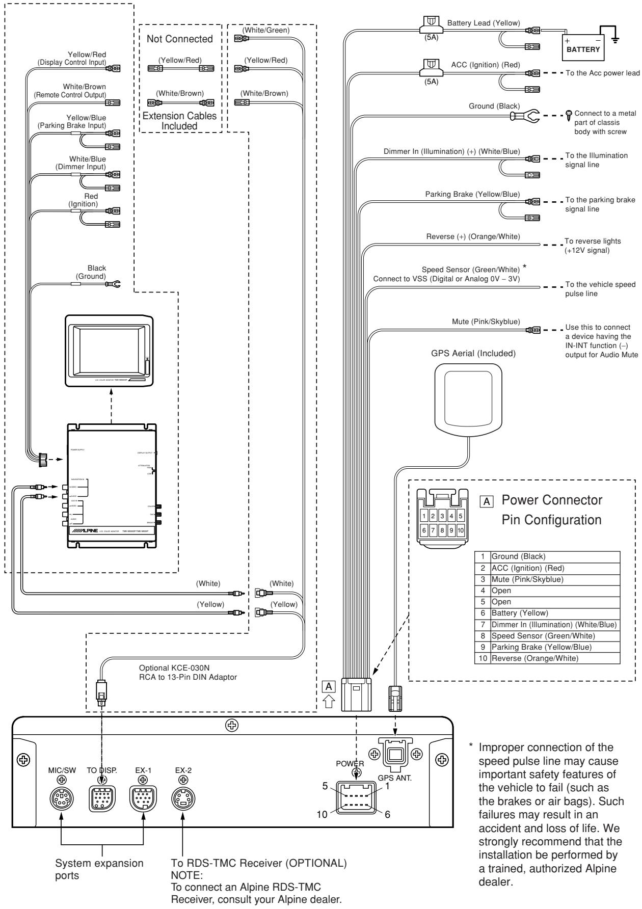
flowchart
graph TD
    A["Yellow/Red (Display Control Input)"] --> B["White/Brown (Remote Control Output)"]
    B --> C["Yellow/Blue (Parking Brake Input)"]
    C --> D["White/Blue (Dimmer Input)"]
    D --> E["Red (Ignition)"]
    E --> F["Black (Ground)"]
    F --> G["Optional KCE-030N RCA to 13-Pin DIN Adaptor"]
    G --> H["MIC/SW TO DISP. EX-1 EX-2"]
    H --> I["System expansion ports"]
    I --> J["To RDS-TMC Receiver (OPTIONAL) NOTE: To connect an Alpine RDS-TMC Receiver, consult your Alpine dealer."]

    K["Not Connected"] --> L["(Yellow/Red)"]
    L --> M["(White/Brown)"]
    M --> N["(White/Brown)"]
    N --> O["Extension Cables Included"]

    P["Battery Lead (Yellow)"] --> Q["5A"]
    P --> R["5A"]
    P --> S["Ground (Black)"]
    T["ACC (Ignition) (Red)"] --> U["To the Acc power lead"]
    V["Dimmer In (Illumination) (+) (White/Blue)"] --> W["To the Illumination signal line"]
    X["Parking Brake (Yellow/Blue)"] --> Y["To the parking brake signal line"]
    Z["Reverse (+) (Orange/White)"] --> AA["To reverse lights (+12V signal)"]
    AB["Speed Sensor (Green/White) * Connect to VSS (Digital or Analog 0V - 3V)"] --> AC["To the vehicle speed pulse line"]
    AD["Mute (Pink/Skyblue)"] --> AE["Use this to connect a device having the IN-INT function (-) output for Audio Mute"]

    AF["GPS Aerial (Included)"] --> AG["A Power Connector Pin Configuration"]

    AH["Power"] --> AI["1 2 3 4 5 6 7 8 9 10"]

    AI --> AJ["1 Ground (Black)"]
    AI --> AK["2 ACC (Ignition) (Red)"]
    AI --> AL["3 Mute (Pink/Skyblue)"]
    AI --> AM["4 Open"]
    AI --> AN["5 Open"]
    AI --> AO["6 Battery (Yellow)"]
    AI --> AP["7 Dimmer In (Illumination) (White/Blue)"]
    AI --> AQ["8 Speed Sensor (Green/White)"]
    AI --> AR["9 Parking Brake (Yellow/Blue)"]
    AI --> AS["10 Reverse (Orange/White)"]

    style AI fill:#f9f,stroke:#333
    style AJ fill:#ccf,stroke:#333
    style AK fill:#ccf,stroke:#333
    style AL fill:#ccf,stroke:#333
    style AM fill:#ccf,stroke:#333
    style AN fill:#ccf,stroke:#333
    style AO fill:#ccf,stroke:#333
    style AP fill:#ccf,stroke:#333
    style AQ fill:#ccf,stroke:#333
    style AR fill:#ccf,stroke:#333
    style AS fill:#ccf,stroke:#333
3. Mounting
Note:
The main unit must be mounted within ±5 degrees of the horizontal plane, left to right, and 30 degrees of the horizontal plane, back to front.
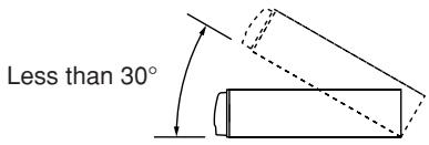
text_image
Less than 30°●When mounting using Velcro fastener
1 Place Velcro fasteners.
Place two pieces of Velcro fasteners onto the mounting surface. The rough side should be facing the navigation unit.
2 Press the Navigation unit onto the Velcro fastener at the mounting position.
Remove the backing to the adhesive on the Velcro strips. Press the Navigation unit onto the mounting location.
Continued to the step 5 "Securing leads, etc."
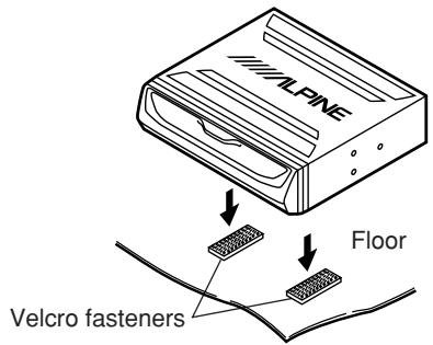
text_image
ALPINE Floor Velcro fasteners●When mounting on the rear tray
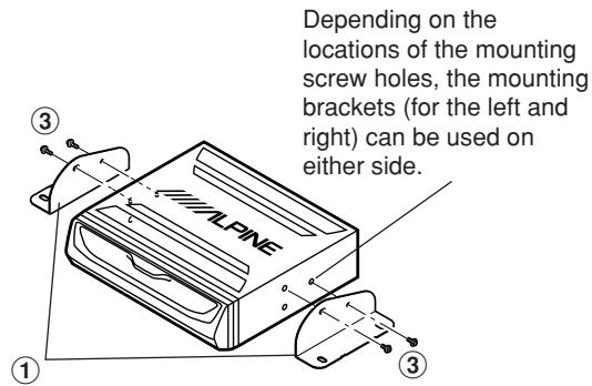
1 Mount the brackets ① on the unit.
Mount the brackets at both sides of the unit with screws with double washer (M5×8) ③.
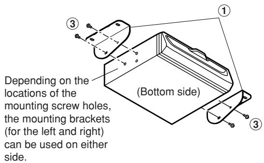
text_image
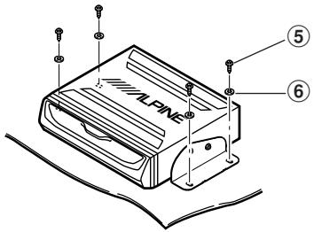
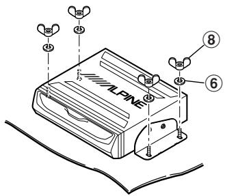
Depending on the locations of the mounting screw holes, the mounting brackets (for the left and right) can be used on either side. (Bottom side)2 Attach the unit on the rear tray.
Attach the unit securely with hex bolts (M6×50) ④, flanged hex nuts (M6) ⑦, spring washers (M6) ⑥, and wing nuts (M6) ⑧.
Continued to step 5 "Securing leads, etc."
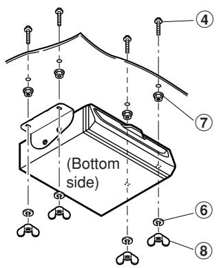
text_image
(Bottom side) ④ ⑦ ⑥ ⑧- When mounting the unit directly on the floor
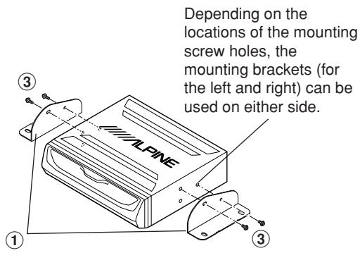
1 Mount the brackets ① on the unit.
Mount the brackets at both sides of the unit with screws with double washer (M5×8) ③.
text_image
Depending on the locations of the mounting screw holes, the mounting brackets (for the left and right) can be used on either side.2 Mount the unit on the floor.
Mount the unit on the floor with flanged self-tapping screws (M5×15) ⑤ and spring washers (M6) ⑥.
Warning: Do not damage pipe or wiring when drilling holes.
Continued to step 5 "Securing leads, etc."
text_image
ALPINE ⑤ ⑥- When mounting with floor base brackets
1 Mount the brackets ①.
Mount the brackets ① at both sides of the unit with screws with double washer (M5×8) ③.
text_image
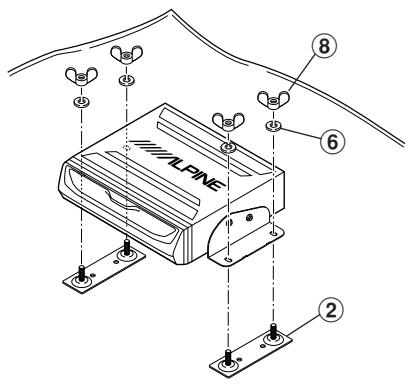
Depending on the locations of the mounting screw holes, the mounting brackets (for the left and right) can be used on either side.2 Determine mounting position of the floor bases ② for placement under the carpet.
text_image
ALPINE ② ⑥ ⑧3 Cut the carpet in "x" shape with a cutter and insert the floor bases ② from under side of the carpet.
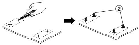
text_image
Diagram illustrating a hand using a pencil to write on a document with a right-angle view, showing step 2 of the process.4 Mount the unit on the carpet with spring washers (M6) ⑥ and wing nuts (M6) ⑧.
Continued to step 5 "Securing leads, etc."
text_image
ALPINE ⑧ ⑥5 Securing leads, etc.
Make sure leads are not pinched by moving parts such as the seat rail, etc. Also check for damaged from sharp edges or protrusion.
6 Connect the battery (−) terminal.
4. Confirmation
1 Turn on the engine key. Make sure the unit is operating correctly by referring to the Owner's Manual.

natural_image
Line drawing of a steering wheel and its open book (no text or symbols)2 Make sure all factory components such as the brake lamps, etc. work correctly.
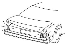
natural_image
Line drawing of a car's front wheel and side panel (no text or symbols)● Remote control holder mounting method
- If the remote control is in direct sunlight, remove it from the holder and keep it in the glove box.
- When the holder cannot be mounted securely with double-sided adhesive tape ⑩, mount it by using screws ⑪.
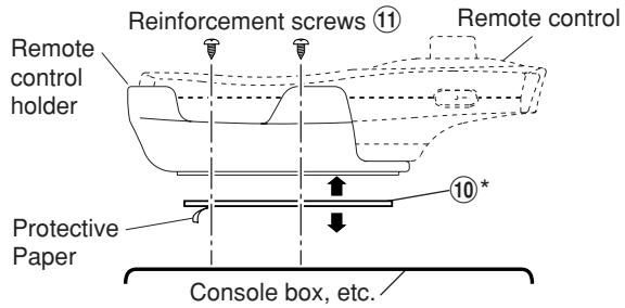
text_image
Reinforcement screws ⑪ Remote control holder Protective Paper Console box, etc. 10 ** Double-sided adhesive tape. (Before attaching the tape, make sure the mounting location is free from dust or dirt.)