2420 - Security Camera AXIS - Free user manual and instructions
Find the device manual for free 2420 AXIS in PDF.


| Product Type | Network Security Camera |
| Brand | Axis |
| Model | 2420 |
| Resolution | 2 Megapixels (1920x1080) |
| Viewing Angle | 90° horizontal |
| Night Vision | Yes, up to 15 meters |
| Power Supply | PoE (Power over Ethernet) or 12V DC |
| Dimensions (W x H x D) | 150 x 60 x 60 mm |
| Weight | 0.5 kg |
| Connectivity | Ethernet 10/100, Wi-Fi (optional) |
| Main Functions | Motion detection, H.264 streaming, night vision, two-way audio |
| Maintenance and Cleaning | Clean the lens with a soft, lint-free cloth. Avoid solvents. |
| Security | HTTPS encryption, IP address filtering, user password |
| Spare Parts and Repairability | External power supply, Ethernet cable, wall mount. Repair by a certified technician. |
| General Information | Indoor/outdoor use, operating temperature: -10°C to +50°C |
Frequently Asked Questions - 2420 AXIS
User questions about 2420 AXIS
0 question about this device. Answer the ones you know or ask your own.
Ask a new question about this device
Download the instructions for your Security Camera in PDF format for free! Find your manual 2420 - AXIS and take your electronic device back in hand. On this page are published all the documents necessary for the use of your device. 2420 by AXIS.
USER MANUAL 2420 AXIS
AXIS 2420 AXIS 2420 W/Lens Network Camera
User's Manual
About This Document
This manual is intended for administrators and users of the AXIS 2420 and the AXIS 2420 W/Lens Network Camera, and is applicable for software release 2.31. Both products are referred to throughout as the AXIS 2420.
This manual contains information for configuring, managing and using the product, as well as a general overview of the product functionality. Detailed instructions for using the product are also available in the on-line Help.
Readers are recommended to use this document as a supplement to the Wizards and other on-line information available via the Web-based interface. Later versions of this manual will be posted to the Axis Website, as required.
Safety Notices
Please observe these safety markings when using this product.
Caution! - Potential hazard that can damage the product.
Important! - Potential hazard that can seriously impair operation.
Do not proceed beyond any of the above notices until you have fully understood the implications.
Legal Considerations
Camera surveillance may be prohibited by laws that vary from country to country. Check the laws in your local region before using the AXIS 2420 for surveillance.
Electromagnetic Compatibility (EMC)
USA - This equipment generates, uses, and can radiate radio frequency energy, and if not installed and used in accordance with the instruction manual, may cause interference to radio communications. It has been tested and found to comply with the limits for a Class A computing device pursuant to Subpart B of Part 15 of FCC rules, which are designed to provide reasonable protection against such interference when operated in a commercial environment. Operation of this equipment in a residential area is likely to cause interference in which case the user at his/her own expense will be required to take whatever measures may be required to correct the interference. Shielded cables should be used with this unit to ensure compliance with the Class A limits.
Liability
Every care has been taken in the preparation of this manual. If you detect any inaccuracies or omissions, please inform your local Axis office. Axis Communications AB cannot be held responsible for any technical or typographical errors and reserves the right to make changes to the product and manuals without prior notice. Axis Communications AB makes no warranty of any kind with regard to the material contained within this document, including, but not limited to, the implied warranties of merchantability and fitness for a particular purpose. Axis Communications AB shall not be liable nor responsible for incidental or consequential damages in connection with the furnishing, performance or use of this material.
Trademark Acknowledgments
Acrobat, Adobe, Boa, Ethernet, IBM, Internet Explorer, LAN Manager, Linux, Macintosh, Microsoft, Netscape Navigator, OS/2, UNIX, Windows, WWW are registered trademarks of the respective holders. Java and all Java-based trademarks and logos are trademarks or registered trademarks of Sun Microsystems, Inc. in the United States and other countries. Axis Communications AB is independent of Sun Microsystems Inc.
Support Services
Should you require any technical assistance, please contact your local dealer. If your questions cannot be answered immediately, your dealer will forward your queries through the appropriate channels to ensure a rapid response. If you are connected to the Internet, you can obtain on-line manuals, technical support, software updates, application software and general corporate information from www.axis.com.
AXIS 2420 User's Manual
Revision 2.0
Part No: 18990
Dated: February 2002
Copyright © Axis Communications AB,
1996 - 2002
Europe €
This digital equipment fulfills the
requirements for radiated emission according to limit B of EN55022/1994, and the requirements for immunity according to EN55024/1998 residential, commercial, and light industry.
Table of Contents
An Introduction to the AXIS 2420. 5
Camera Models 5
Product Overview 5
Features and Benefits 6
Physical Description 9
Front Panel 9
Rear Panel 10
Mounting the AXIS 2420 11
Checking The Hardware Inventory.... 11
Installing on a Network. 12
Installing via a Modem 14
Focusing Your Camera.... 17
Configuring Your Camera 18
Configuration Using the Wizards 18
The Administration Tools 20
System Security 23
Motion Detection 24
COM-Ports, Modems and Pan-Tilt-Zoom Devices 25
The Factory Default Settings 30
Choosing Your Application 31
The AXIS 2191 Audio Module 38
Installing the Audio Module 40
Configuring the Audio Module 41
Using the Audio Module with Your Camera 42
Appendix A - Troubleshooting. 47
Appendix B - Other IP Setup Methods 51
Appendix C - Lenses and Advanced Focusing 54
Appendix D - Customizing Your Camera 60
Appendix E - Updating the Firmware 63
Appendix F - The Unit Connectors. 64
Appendix G - High-Speed Services 69
Appendix H - Technical Specifications. 70
Deutsch
The AXIS 2420 Network Camera is available in 4 different variants:
- The AXIS 2420 (PAL) - supplied without a lens.
- The AXIS 2420 W/Lens (PAL) - supplied with a DC-Iris varifocal lens.
- The AXIS 2420 (NTSC) - supplied without a lens.
- The AXIS 2420 W/Lens (NTSC) – supplied with a DC-Iris varifocal lens.
This information provided in this manual is applicable to all variants, unless otherwise stated. All product variants are referred to throughout the manual as the AXIS 2420.
Product Overview
The AXIS 2420 is a digital network camera running TCP/IP. It includes all of the required networking connectivity for distributing monitored images over a secure intranet or the Internet. With its own built-in Web server, the AXIS 2420 provides high-quality imaging, and full Web-based control of the product management and configuration functions via a browser over your network.

natural_image
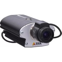
Exterior view of a black and silver AXIS camera with visible lens and control knobs (no text or symbols on body)The AXIS 2420 Network Camera (lens only supplied with AXIS 2420 W/Lens).
Connecting directly to Ethernet or Fast Ethernet networks, the AXIS 2420 is a standalone digital network camera that will also connect to a local Internet Service Provider using an external modem.
To simplify the installation process, the Web-based interface provides an Installation Wizard and an Application Wizard, which help you towards a seamless and automated integration into your networking and application environments.
Including a video output via a standard BNC connector, the AXIS 2420 also connects directly to any analog CCTV system to provide instant Plug-and-Watch integration into two parallel imaging networks - traditional analog, and modern digital.
Suitable for use in outdoor enclosures, the AXIS 2420 includes in-picture motion detection, making it the ideal professional surveillance tool.
Features and Benefits
Ease of Use - The AXIS 2420 is completely independent of any other server and requires no special hardware or viewing software. All you need to view live pictures over your network is Netscape Navigator 4.x or Microsoft Internet Explorer 4.x/5.x (used with the Axis ActiveX component or Java Applet). Whatever your choice of browser, the AXIS 2420 supports complete Plug-and-Watch functionality; so, all you need to do is assign a valid IP address.
Simple Administration - Using a standard browser, the AXIS 2420 is configured and managed directly from its own Web pages.
Cost-effective - The AXIS 2420 provides a reliable and low-cost resource for high-quality imaging over the network without the hidden accessories normally required by other digital cameras; such as, expensive software, management workstations, dedicated applications, video cabling or PC frame-grabber cards. Use the AXIS 2420 as a night watchman and exploit the downtime on corporate networks. With the AXIS 2420 there's no need to install coaxial cabling - just use your existing Ethernet networks for remote surveillance imaging - as well as for data communication.
Built-in Support for the AXIS 2191 Audio Module - The AXIS 2420 can be used directly with this add-on component, which enables live audio on your camera. The AXIS 2191 is supplied separately.
Open Standards Environment - Supporting TCP/IP networking, SMTP, HTTP and other Internet-related protocols, the AXIS 2420 can be used in mixed operating system environments; such as Windows, UNIX, Macintosh and OS/2. It integrates easily into other WWW/Intranet applications and CGI scripts.
Outdoor Use - The AXIS 2420 is a professional product including full DC-iris control and is shipped either without a lens (AXIS 2420) or with a DC-Iris varifocal lens (AXIS 2420 W/Lens). Both variants can alternatively be fitted with any standard C-CS type lens. Installed into an appropriate outdoor housing, the camera makes an ideal remote monitoring tool for outdoor use. Follow the accessories links for information on appropriate outdoor casings for the AXIS 2420 on our Website at www.axis.com.
Motion Detection - Sophisticated motion detection with in-picture alarm programming, and multi-window triggering for professional remote monitoring over TCP/IP networks, or via a modem.
Standard Image Format - In professional surveillance applications it's often critical for every recorded image to be of a high quality. That's why, in contrast to many inferior solutions that simply store image changes from one frame to another, the AXIS 2420 delivers up to 25/30 (PAL/NTSC) full, high-quality frames per second. Your pictures can be viewed using any standard browser and the data integrity of your recorded images is always assured.
Image Updating - The on-board AXIS ETRAX 100-LX processor combined with the revolutionary AXIS ARTPEC-1 Real Time Picture Encoder provides an amazing power-synergy to deliver up to 25/30 frames/second over 10Mbps or 100Mbps networks.
High Compression - The AXIS ARTPEC chip affords both an efficient and variable ratio of JPEG image compression that can be defined by the user.
Analog or Digital - The AXIS 2420 includes a standard BNC video output which means that apart from a connection over a modem or network, you can simultaneously connect the AXIS 2420 to any analog CCTV system. That gives you simultaneous video imaging over diverse surveillance systems.
External Device Connection - Supporting RS-232 and RS-485 communication protocols, the AXIS 2420 includes the physical interfaces for connecting a variety of external devices; such as, Pan/Tilt/Zoom devices, doorbells, switches and alarm relays. Develop your own PHP-based programing scripts for creating a variety of security applications triggered on time or alarm-based events. You can even drive annunciators and other audible alarm devices using the relay output.
Wide Range of Applications - The AXIS 2420 offers live video over internet networks and the Internet, and is ideal for use with many of today's high-speed internet services. Allowing remote access directly from your Web browser, you can view live images, manage, and control the AXIS 2420 at any time and from anywhere. The AXIS 2420's sophisticated features make it the ideal tool for intruder detection, industrial process control, public surveillance, visual security, and image archiving applications.
Modem Support - The Point to Point Protocol (PPP) support allows you to use your AXIS 2420 remotely over a serial link, just as if it were located on your local network. You can initially set up the AXIS 2420 over the network, or use a computer connected directly to the AXIS 2420 via the supplied Null Modem cable. The AXIS 2420 is accessed using a standard Dial-up (PPP) connection.
ISP Support - Arrange for the image files to be uploaded to an Internet Service Provider (ISP) and provide the global Internet community with browser access to your live images. Select any of the supported ISPs from the embedded Web-based Wizards, or choose your own preferred ISP as an imaging repository for your images.
Security - The AXIS 2420 includes a self-contained Web server, which means that your digital images can be protected just like any other Internet host. Data protection is normally implemented by your Network Administrator using the unit security settings in combination with an organization's Internet firewall. The Administrator can subsequently restrict image access to specific individuals or groups, or alternatively allow global access.
Linux Operating System - The AXIS 2420 includes modified versions of the Boa Web server, and Linux operating system - both of which are freely distributed under the GNU General Public License, as published by the Free Software Foundation. This software provides a stable and reliable platform for open-source development of the product. In accordance with the GNU General Public License, Axis has published the kernel for this product at http://developer.axis.com/.
Physical Description
Please read the following information to familiarize yourself with your AXIS 2420, making particular note of where the connectors and indicators are located. This section provides a useful reference when installing the product.
Front Panel

Important!
If you are using the AXIS 2420 in an outdoor application, it must be housed in a weatherproof enclosure and must be fitted with a DC-Iris lens to automatically regulate the amount of light entering the camera. Prolonged exposure to direct sunlight or halogen light will damage the CCD. Consequently, Axis recommends observing extreme caution when installing the camera in strong sunlight. Failure to do so may invalidate the product warranty. The AXIS 2420 W/Lens is supplied with a DC-Iris lens as standard.
Rear Panel

Note: The power supply for your AXIS 2420 is country-specific. Please refer to the Hardware Inventory on page 11 and check that the type of power supply you are using is correct.
Mounting the AXIS 2420
The AXIS 2420 is supplied without a mounting assembly. Screw holes for attaching the camera to an assembly are provided on both the top and bottom surfaces of the unit, for easy installation on a wall or from a ceiling.
The screw hole has an internal dimension of 1/4" UNC.

The AXIS 2420 is also suitable for outdoor use, but it must be mounted in a weatherproof enclosure and must be equipped with a DC-Iris lens. If these conditions are not met when using the camera outdoors, the product warranty will be void.
Checking The Hardware Inventory
Check the items supplied with your AXIS 2420 against the list below and contact your dealer if you find anything is missing or damaged.
| Item Title/Variants Part Number Item Title/Variants Part Number | |||||
| Network Camera | AXIS 2420 (PAL) | 0127-001-01 | Power Supply(PS-D) | Europe 14233 | |
| AXIS 2420 (NTSC) 0127-011-01 UK 14234 | |||||
| Network Camera with Lens | AXIS 2420 W/Lens (PAL) | 0127-101-01 | Australia | 14255 | |
| AXIS 2420 W/Lens (NTSC) | 0127-111-01 | USA | 14253 | ||
| Null Modem Cable | - | 16954 | Japan | 14254 | |
| DC-Iris Connector | 4-pin male | 18043 | ExtensionCable for PS | 3.3 meter | 15187 |
| This Document AXIS 2420 User's Manualv2.0 | 18990 | TerminalConnectors | x 2 | 16817 | |
| Disk media | AXIS Network Camera CD v2.0 (or later) | WarrantyDocument | - | 18640 | |
Installing on a Network
• Macintosh users - Please refer to Notes for Macintosh Users, on page 53.
- Easy installation - Use The AXIS IP Installer. See Using the AXIS IP Installer, on page 52.
- Quick installation – Follow the instructions below to install the AXIS 2420 on an Ethernet network.

- Using an appropriate method for your operating system, assign your product with a unique IP address from a computer on your network, as follows:
Windows only - Start a DOS window and type in the commands shown below:
Syntax:
arp -s
Example:
arp -s 172.21.1.200 00-40-8c-10-00-86 172.21.1.193 ping -t 172.21.1.200
UNIX only - Type these commands in the command window:
Syntax:
arp -s
Example:
arp -s 172.21.1.200 00:40:8c:10:00:86 temp ping 172.21.1.200
Note: In some Unix systems, the arp command can be located in a directory that is not on the command path.
You will now see 'Request timed out...' messages repeatedly returned in the window.


Verifying and Completing the Installation From Your Browser

Important!
- Upon delivery, the AXIS 2420 is configured for open access (anonymous users). The unit is supplied with one pre-configured Administrator username and password, set to root and pass, respectively. The Administrator password must be changed immediately to prevent unauthorized access to the Admin Tools and/or product images, as defined in the Security Settings.
- To enable the updating of images in Microsoft Internet Explorer, set your browser to allow ActiveX controls and perform a once-only installation of Axis' ActiveX component onto your workstation. If your working environment restricts or prohibits the downloading of additional software components, you can alternatively, from the Image Settings, configure your AXIS 2420 to use a Java applet for updating the images. Refer to the on-line Help for more information.

Installing via a Modem
The information in this section describes how to connect the AXIS 2420 to a serial modem for transmitting images over a dial-up connection.
Important!
- Although instructions for configuring the AXIS 2420 using a null modem cable are provided below, it is recommended that (if possible) the unit is initially installed and configured over a network.
- The information and screen examples featured within this section are specific to Windows NT. Although similar to the Dial-Up implementations in other versions of Windows, small deviations in the dialog instructions for other operating systems should be expected. Refer to your system information for further information on creating a Dial-Up modem connection if you are using any other operating system.
- Windows Dial-Up Networking and TCP/IP must be correctly installed prior to commencing with the modem cable connection. Detailed information on how to check this is provided in Windows Help.
Connecting Your Computer Using the Null Modem Cable

10 Click Close.
Creating a Dial-Up Networking Connection
Follow the steps below to create a dedicated Dial-Up networking connection to your product:
1 Double-click My Computer and then double-click the Dial-Up Networking icon.

Refining the Dial-Up Networking Properties
Having created the Dial-Up connection for your AXIS 2420, follow the steps below to refine the connection properties:
① From the Dial-Up Networking dialog, right-click the dedicated Dial-Up connection previously created for your AXIS 2420 (AxisCamera in this example). Select Properties.


⑦ Click the Scripting tab and ensure that the Start terminal screen minimized checkbox is checked. Click OK to exit Dial-Up Networking Properties.
Initiating the Dial-Up Connection
Important!
Please ensure that the Null Modem Cable is correctly installed and that the relative connection properties are correctly configured before initiating a Dial-Up connection. Step-by-step instructions on how to do this are provided on the preceding pages of this section.
1 Double-click My Computer and then the Dial-Up Networking icon.
② Double-click the Dial-Up connection icon previously created for your AXIS 2420 (AxisCamera in this and previous examples).
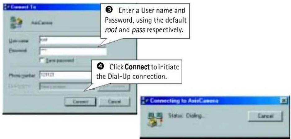
Verifying the Modem Connection and Completing the Installation
Having initiated your Dial-Up connection, as described above, you can quickly test the connection by accessing the AXIS 2420 from a standard browser, such as Netscape or Internet Explorer, as follows:

Focusing Your Camera
If you have installed your camera in a location where you are unable to see the video images directly in a browser, follow the instructions below to achieve a good basic level of focus for your AXIS 2420:
① Power on the AXIS 2420 and then wait at least 10 seconds.
② Turn the focus ring to its extreme Far-focus (F, •) position.
3 To enable the Focus Assistant: using a suitably pointed object, press and hold the Control Button until the Status Indicator flashes Yellow.
④ Turn the focus ring to its extreme Near-focus (N) position.
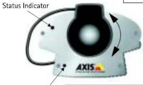
Control Button
⑤ Finally, turn the focus ring slowly towards the Far-focus (F, ∞) position - until the Status Indicator displays Green; that is, until a Good level of focus (>80%) is achieved.
⑥ Return to your browser application and review the picture quality. Repeat step 5 only if you consider the focal distance as too distant - until you are satisfied with both the focal distance and focus quality.
7 To exit the Focus Assistant: press and hold the Control button until the Status Indicator flashes Yellow. The Status Indicator displays Green when the Focus Assistant is closed.
For more information about lenses and focusing, please see Lenses and Advanced Focusing, on page 54.
Configuring Your Camera
Before you begin:
Successful installation of the product is prerequisite to configuring the unit. You should therefore read the following information before commencing with this section:
• Installing on a Network, on page 12, or Installing via a Modem, on page 14, and then
- Choosing Your Application, on page 31.
Important!
Javascript must be enabled in your browser for the AXIS 2420 Web-based interface to work.
After installing the product, your AXIS 2420 is now attached directly to a local area network, or connected to a local PC using the supplied Null Modem Cable. You are now ready to proceed with the configuration of the unit.
This section describes how to use the product Wizards for configuring and integrating the AXIS 2420 into your application environment, and provides a general overview of the Web-based Administration Tools.
Note: On-line help is stored internally in the AXIS 2420 and is available from most pages in the Web interface. Containing comprehensive details on all product parameters, the on-line help is your first point of reference when configuring and managing the unit, and particularly useful for resolving any administration queries.
Configuration Using the Wizards
For speedy development of your application, the AXIS 2420 provides two easy-to-use Wizards; the Installation Wizard and the Application Wizard, both of which are recommended for novice and advanced users alike.
Important!
- When accessing the Administrator Tools for the first time, you will be assumed to be the administrator and will be logged in as such, with the user name root and default password pass.
- You must change the root password as soon as possible. Until this has been done, the security features in the product be will not be enabled. Furthermore, all Axis products are shipped with the same password by default. For further information, refer to System Security, on page 23.
- Prior to accessing the Installation Wizard or Administration Tools over a network, you must first set the IP address, using ARP as described on page 12, or with any alternative method as described in Appendix B - Other IP Setup Methods.
The Installation Wizard
The Installation Wizard provides a quick and easy way of defining the basic settings for your installation - as explained in the Administration Tools Overview, on page 21.
Using the Installation Wizard
- Start the Installation Wizard from the product's Home Page or from the administration tools page.
- Click Start>. Follow the instructions to complete the configuration.
- Click the Finish button to save the settings to the camera.
The Application Wizard
The Application Wizard is started from the main Administration Tools page. It provides a quick and easy way of making your application settings - as defined in the Administration Tools Overview, on page 21.
Using the Application Wizard
- Start the Wizard from the Administration Tool Page.
- Click Start>. Follow the instructions and reply to the questions asked by the wizard.
- Click the Finish button to save the settings to the camera.
The Administration Tools
Whether you are viewing images directly over the network, or transmitting images over a modem, you can use the Web-based Administration Tools for configuring and managing your AXIS 2420 at any time. After initially setting up the AXIS 2420 with the Installation Wizard, these tools are ideal for more advanced users.
Accessing the Tools
Follow the instructions below to access the Administration Tools using a browser:
- Start the browser and enter the name or IP address of the AXIS 2420 (or any DNS name if you are accessing the unit via the Null Modem Cable) in the location/address field.
Example!
http://172.21.1.200/
- The AXIS 2420 Home page is now displayed. Click Administration Tools.
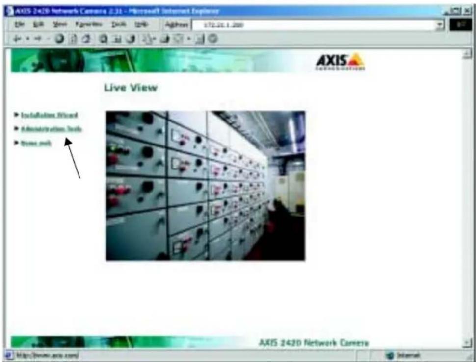
- The Administration Tools are now presented as links on the Administration Page. Simply click the relevant link for the parameters you want to configure.

Administration Tools Overview
The table below provides a one-stop overview of the Administration Tools:
Settings Tool Description
| Image | Focus the camera using the Focus Assistant, adjust the Auto Iris settings, and define image attributes for your AXIS 2420. |
| Network | Configure the TCP/IP and SMTP settings, make the settings for Dynamic IP Address Notification and enable DHCP (see below) and BOOTP. |
| System | Set the product Date and Time, create and delete users and passwords, and modify the Administrator's password. By default, the AXIS 2420 supports anonymous user access, which means that anybody on the Internet/intranet has access to the video images from a browser. To restrict open access, simply register a single authorized user. |
| External Devices | Configure the COM-ports on the AXIS 2420 to use modems, the AXIS 2191 Audio Module, (supplied separately) or other external devices. For information on how to configure and use the audio module, please see The AXIS 2191 Audio Module, on page 38. Select the operational modes for the RS-232 and RS-485/422 ports, and configure other external devices, such as PTZ devices. Make general communication settings for your modem and specific settings for the Dial-up Modem Connection to your ISP/Web server. |
Applications Tool Description
| Operation | Choose to run your AXIS 2420 in Sequential or Alarm Mode, and specify how and where images will be uploaded. Note that you must enable your application by following the Enable link. If there is already an older application present, then this must first be disabled before you enable your new application. |
| Motion Detection | Create and enable in-picture motion detection windows. These are used to trigger alarms whenever significant movement occurs in the detection window. Create up to three drag-and-drop windows and restrict alarms to movement in specific areas. Each motion detection window has a set of profile sliders for making individual settings. |
| Layout | Determine the Layout for the Web page in which your images will appear. Customize the page to your own design and include your own logos, links and title texts, and enable or disable specific function buttons. |
Wizards Description
| Installation | The Installation Wizard helps you quickly get the product up and running. Recommended for use by both novices and experienced users alike. |
| Application | This Wizard will guide you through the process of setting up your application. |
Support Description
| General Displays various useful information about how and where to get help. | |
| Release Notes | View the product Release Notes, the Parameter List, and/or initiate a Restart of the unit. |
| Parameters Displays the complete list of settings currently valid in the unit. | |
| Log File | Displays the log file showing all of the commands executed since the last restart. |
| Restart/ Reset | Provides commands for restarting the unit and for resetting to the factory default settings. |
| About Displays information about the development of this product. | |
Help Starts the product's on-line help.
Live View Opens the product's home page.
DHCP
DHCP (Dynamic Host Configuration Protocol) is a protocol that lets network administrators centrally manage and automate the assignment of Internet Protocol (IP) addresses in an organization's network.
Important!
DHCP should only be enabled if you know which IP address the AXIS 2420 will get from the DHCP server, or if your version of DHCP can update a DNS server, which then allows you to access the AXIS 2420 by name. If DHCP is enabled and you cannot access the unit, you may have to reset it to the factory default settings (see page 30) and then perform the installation again (see page 12).
System Security
To prevent unauthorized use of the camera, the AXIS 2420 supports multi-user password protection, and access can be restricted to defined users only. A system Administrator has unrestricted access to the product's Administration Tools and can determine the registration and access rights for all users.
Notes:
- When accessing the Administrator Tools for the first time you will be assumed to be the administrator and will be logged in as such, with the user name root and default password pass.
- The root password must however, be changed as soon as possible. Until this has been done, the security features in the product be will not be enabled. Furthermore, all Axis products are shipped with the same password by default.
User Access Rights
As an Administrator, click System and then Users to perform any of the following tasks:
• define or edit the administrator (root) password
• define, add and delete user names and passwords
- assign individual access rights to a selected user, where each user is awarded with one or more of the following levels of access:
- Admin: a user granted with Admin rights has unrestricted access to the Administration Tools and can consequently determine the registration of all users.
- Dial-in: provides the user with dial-in modem access only.
- View: provides the lowest level of access, which only allows the user to view images.
Important!
By default, the AXIS 2420 supports anonymous user access, which means that anybody on the Internet/intranet has access to the images (but not the Admin tools) from a browser.
To restrict open viewing access, simply register a single authorized user. This effectively revokes the anonymous user service and restricts access to specified users. If the anonymous user service is satisfactory for your application, simply do not add any users. The Administrator's own settings are enough to provide anonymous viewing access.
Motion Detection
The AXIS 2420 includes in-picture motion detection, for creating specific surveillance zones in the image area. You can create, name, and use up to 3 motion detection windows. You can also move, resize, or delete them at any time.
Use motion detection to generate an alarm whenever movement occurs in the specified area. Simply click and drag with your mouse in the image area to create and automatically enable a motion detection window. Movement outside the window area is ignored.

Creating a Motion Detection Window
Follow the instructions below to create a motion detection window in your surveillance area:
- Click the New button to create a new motion detection window or simply click in the image.
- Drag the bottom right corner of the highlighted rectangle to cover the area you wish to monitor. Release the button. To move the window, click and drag the title bar to the desired location.
-
Enter a unique name for your window in the Name field.
-
Set the Size, History and Sensitivity profile sliders accordingly for the surveillance area. The sliders are described briefly below. A fuller description is provided in the on-line help.
-
Size - The relative size of the moving object in the motion detection window.
- History - Specifies for how long a moving object will trigger the motion detection before being regarded as non-moving.
-
Sensitivity – The higher the level, the less contrast is needed to trigger the motion detection.
-
If you are using Netscape Navigator, click Save to save your motion detection windows. In Internet Explorer the windows are saved automatically.
- Having created a new motion detection window, you are now ready to test it. Create some physical disturbance within the motion window area and check the motion indicator box. If the window does not react as you want it to, adjust the sensitivity slider. The horizontal line will move to reflect the new setting. When the motion indicator shows activity in the image, it is the activity above the horizontal line which will trigger any alarms you may have set.
Note: Motion detection windows support simple drag-and-drop functionality, which allows you extend or reduce the window area at any time. To delete a window, select the window and press Delete.
COM-Ports, Modems and Pan-Tilt-Zoom Devices
The supported COM-ports are one RS-232 and one RS-485/422 port. The RS-232 port is connected via the 9-pin D-sub connector on the rear of the unit and the RS-485/422 interface is via the I/O-B terminal block connector.
The RS-485/422 port supports the connection of an external device, usually a Pan Tilt unit. The RS-232 port can be used for the same purpose, but also for connecting a modem or the AXIS 2191 Audio Module. For details on how to connect and configure the AXIS 2191, please see The AXIS 2191 Audio Module, on page 38.
Note: Only one port at a time can be used for controlling a Pan Tilt device.
Setting the RS-232 Port for use with a Modem
From the External Devices link on the Administration page, select the RS-232 port and click the radio button for Modem. Some basic modem settings can now be made directly from this page. Click Save. To further configure the modem, click Modem (also from the main Administration page) and then General or ISP.
Modem
The Modem page allows you to set your specific modem type and configure it, using the following parameters:
- Disable incoming calls - use this only if you will not need to dial-in to the AXIS 2420.
- Modem Type - set the brand of modem and provide a specific Initstring, if required.
- Communication Settings - advanced settings for your modem. Please see the documentation for your modem.
- Callback - use this to get your modem to return your call. The number of ring signals to wait before callback and the number of seconds to wait before disconnecting can both be set.
ISP
This page provides the fields for entering the information specific to your own ISP. If your own ISP is not listed, use the Generic setting. The settings available are; the number you dial to your ISP, your user name and password, the connection type and the re-dialing properties. You can save on phone bills by setting the connection type to Closes After or Optimized. See the on-line help for more information.
Using Pan-Tilt-Zoom Devices
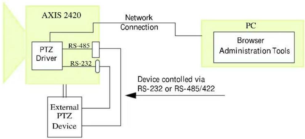
There is a wide range of Pan-Tilt-Zoom (PTZ) devices available on the market today. Some of these can be used with your AXIS 2420 to provide a simple means of remotely aiming and controlling your camera. A PTZ device connects directly to the AXIS 2420 via the RS-232 port or RS-485/422 port on the back panel of the camera. Both ports support the use of these devices, but only one port at a time can be used for the purpose.
Apart from the COM settings shown by default for the COM ports, selecting External Device for the port will also reveal a section called Pan Tilt Settings. The drop-down list allows you to select the driver for your PTZ device. The devices in the list are the ones currently supported by the AXIS 2420. For the latest information concerning supported PTZ drivers, please see the Axis Web at www.axis.com.
Connecting PTZ Devices
The diagram below illustrates how the AXIS 2420 connects to your workstation and PTZ device.
flowchart
graph TD
    A["AXIS 2420"] --> B["PTZ Driver"]
    B --> C["RS-485"]
    B --> D["RS-232"]
    C --> E["External PTZ Device"]
    D --> E
    E --> F["Network Connection"]
    F --> G["PC Browser Administration Tools"]
    H["Device controlled via RS-232 or RS-485/422"] --> E
Installation Procedure
Follow the instructions below to install a PTZ device:
- Attach the PTZ device to the RS-232 or RS-485/422 port of the AXIS 2420 using the appropriate cable.
- On the AXIS 2420 Home Page, click Administration Tools.
- Click on External devices and then select the port you wish to use for your device. Click Save.
- Now click on the PTZ link. Select the driver that corresponds to your PTZ device from the drop-down menu.
- You can now change the default settings and preset positions (see page 29) by clicking the buttons provided and by selecting values from the drop-down lists. After making your settings, click Save. If your Pan Tilt device also supports the Zoom function, refer to the devices's documentation for details on how to connect a zoom lens.
When using a Pan-Tilt device, the camera's home page will show Pan and Tilt bars, as well as a drop-down list for preset positions, if this is supported. Note that the presence and appearance of some functions (e.g. the zoom function) will depend on the Pan-Tilt device being used.

Preset Positions
To enable quick and accurate camera positioning to known camera hotspots, the Administrator can set and save any camera orientation as a named entity - a Preset Position, which can be used at any time. The orientation for the camera is controlled by Pan and Tilt control bars.
Follow the instructions below to define a preset position:
- From the COM-Port page, click the Preset Position button. An image from the camera (at its current position) is displayed in a new window.
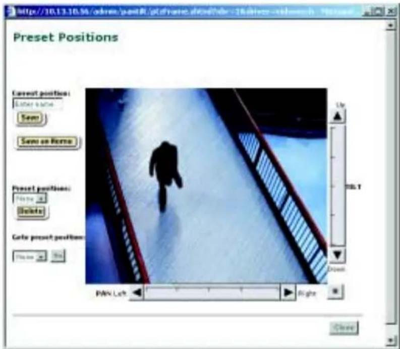
- By clicking in the image or by using the Pan Tilt and Zoom (if supported) control bars, move the camera to the desired position.
- Enter a descriptive name in the Current Position field.
-
Click Save to register the new preset position with the AXIS 2420 and then check that the entered name is included in the Preset Positions drop-down list. You can alternatively choose to save the position as a new Home position, by clicking the Save as Home button.
-
Click Delete if you want to remove the selected preset position.
Established preset positions are selected from the Preset Positions drop-down list on the application viewing page.
The Factory Default Settings
In certain circumstances, it may be necessary to reinstate the Factory Default settings for your AXIS 2420. This is performed by clicking the appropriate button in the Administration Tools, or by pressing the Control Button (see the illustration on page 9). Follow the instructions below to reinstate the product factory default settings using the Control Button:
- Switch off the AXIS 2420 by disconnecting the power cable.
- Press and hold the Control Button pressed, and reconnect the power supply cable.
- Continue to keep the Control Button pressed until the Status Indicator displays yellow (note that this may take up to 15 seconds), then release the Control Button. When the Status Indicator displays green (which can take up to 1 minute) the AXIS 2420 will then have been reset to the original factory default settings.
Note: Reinstating the factory default settings causes all parameters (including the IP address) to be reset.
Choosing Your Application
The AXIS 2420 can be used in a wide variety of applications and installs directly onto an Ethernet network, or over a V.90-compatible modem. Requiring no additional software on your viewing desktop, it is a completely self contained unit that delivers crisp live images to your browser. Using the Web-based Administration Tools and easy-to-use Wizards, you can quickly and easily develop your application.
This section contains a few examples of typical applications, and also includes other reference information to help you configure your product.
Networking Applications
If you have access to an Ethernet connection at your installation location, simply plug the AXIS 2420 into your LAN/WAN and set the IP address. You are then ready to view images from any desktop over your network.
However, the AXIS 2420 offers more than just convenient access to live images over the network. Using the available Wizards to guide you through the process, you can quickly and easily configure your product for a variety of exciting applications, including:
- Using Motion Detection to generate alarms and trigger uploads of recorded images.
- Connecting an external alarm device, e.g. a door switch, to the AXIS 2420 and uploading pre and/or post alarm images to a target FTP server when an alarm or time-based event occurs; and optionally, sending e-mail alerts containing images, and/or a link to the camera.
- Uploading images to a remote FTP server on a LAN/WAN network to accommodate a large viewing audience, where a high volume of Web page hits is anticipated.
Note:
You can access live images from a desktop browser on your network as soon as the AXIS 2420 is physically installed on your network. Both advanced and novice users should then use the Wizards to configure the chosen application. After the basic configuration has been established with the Wizards, advanced users can then use the Web-based Administration Tools for refining the application.
Picture frequency for Networking Applications
When used in a TCP/IP networking environment, the AXIS 2420 delivers up to 30/25 (NTSC/PAL) images/second. The perceived frame rate in your browser is typically limited by:
- the number of clients accessing the images
- your computer and browser
- the chosen image resolution and compression
- the lighting conditions at the point of installation
• available network bandwidth - the complexity of detail and color variation within the image
Note: The AXIS 2420 is available in NTSC and PAL variants to accommodate the different power supply frequencies in the USA and Europe.
Image Compression Ratios
Although the file size of a JPEG-compressed image depends upon the actual content of the image, images containing great detail generally generate larger files. Image quality is largely controlled through the level of compression; where high compression yields small files, and low compression maintains higher image quality at the expense of larger files. The table below is derived from real-life tests, and defines the average file sizes for each supported image resolution:
| NTSC PAL | |||||
| Resolution File size (kb) Max fps* Resolution File size (kb) Max fps* | |||||
| 4CIF (704 x 480) | 7 - 150 | 10 | 4CIF (704 x 576) | 8.5 - 180 | 8 |
| CIF (352 x 240) | 1.4 - 40 | 30 | CIF (352 x 288) | 1.7 - 50 | 25 |
* Maximum performance for a single viewing client.
Note: Using a modern computer will avoid introducing any unnecessary constraints on the image frequency.
Modem Applications
If a local network connection is not available at your chosen point of installation, you can alternatively connect your AXIS 2420 to a V.90-compatible modem and quickly configure any number of exciting applications using the Wizards; including:
- Using Motion Detection to generate alarms and trigger uploads of recorded images.
- Uploading single or pre/post alarm image sequences to your ISP over a modem connection, when an alarm or time-based event occurs; and optionally, sending e-mail alerts containing images or links to pre/post alarm images stored by your ISP.
- Sequentially uploading images to an ISP (Internet Service Provider) over a modem connection and publishing images to the whole Internet community.
Important!
- Although the AXIS 2420 is compatible with most V.90-compliant modems, Axis takes no responsibility for V.90 modems that fail to work with the product.
- When the AXIS 2420 is dialing out it will obviously not be possible to dial-in to it. If you configure an interval during which the camera will not be dialing out, this will allow you to dial-in and make any necessary changes, etc. If you also have an Ethernet network connection, then this will always be available, even if the camera is dialing out via the modem connection.
Configuration
All modem applications must initially be configured from a browser on a local computer. If available, you should always use an Ethernet network for this purpose, even if the actual application will be using a modem. When there is no network available, you can use the supplied Null Modem Cable to create a direct connection to the AXIS 2420 from the computer. This direct connection is only intended as an alternative for the initial configuration of the modem application in the absence of a network. The Null Modem Cable should not be used for any other purpose.
Note:
Once the modem connection has been created and the AXIS 2420 is physically connected to the modem, you can then connect to your camera in exactly the same way as you would to your ISP - with no further configuration whatsoever. You use the Installation and Application Wizards to establish the basic parameters for your application, and advanced users can optionally use the Administration Tools to refine their application once the basic configuration is complete.
Picture Frequency for Modem Applications
The speed of your modem link is a dominant factor in determining the frequency at which images are displayed in your browser, and an average-sized image is normally transmitted in 2-4 seconds. For alarm applications, where picture updating is critical, images are buffered into internal memory prior to being uploaded to your ISP or Web server. This means that a slow connection will not prevent your images being correctly saved and transmitted.
Proprietary ISP Dial-up Protocols
If you need to install any special software before initiating a dial-up connection, it is likely that your ISP is using proprietary protocols incompatible with the standard-based AXIS 2420. In these circumstances, we recommend that you ask your ISP for an alternative dial-up service that allows for standard dial-up networking. Axis does not guarantee the compatibility of this product with any ISPs requiring the use of proprietary or non-standard software as a pre-requisite for dial-up connections.
Sequentially Uploading Images to an FTP Server/ISP
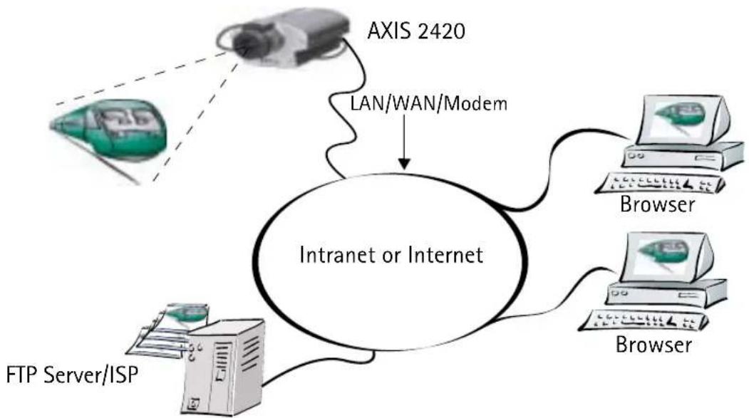
Ideal for busy Web sites on large or small networks, this application uploads images to an FTP server/ISP, via the network or a modem, and is perfect for applications where a large audience is expected. Your images can then be accessible to several specific users, or to the whole Internet community! You can select any of the ISPs in the Application Wizard, or specify your own.
flowchart
graph TD
    A["FTP Server/ISP"] --> B["Intranet or Internet"]
    C["AXIS 2420"] -->|LAN/WAN/Modem| B
    D["Browser"] --> B
    E["Browser"] --> B
Simply install the AXIS 2420 directly on your local Ethernet network or via a modem, and then complete the Installation and Application Wizards to develop an active application that will upload images to a designated FTP server - as a sequential stream that is unlimited, or restricted to specified time periods. You organize the times and the frequency at which your images are taken and uploaded to the target server.
Installation and Configuration Overview
Configure the AXIS 2420 to actively upload images to an FTP server/ISP, as follows:
- Connect the AXIS 2420 to your local network, or, if no network is available, use the null modem cable to create a direct connection to a local computer. Refer to Installing on a Network, on page 12, or Installing via a Modem, on page 14.
- Open the Home Page in your browser and start the Installation Wizard. Complete the Wizard to establish the basic settings - selecting the connection method in the Modem or Network dialog. Refer to Configuring Your Camera, on page 18.
- Continue the configuration using the Application Wizard, defining the target FTP server/ISP and setting Sequential as the mode of operation. You will also be able to make settings for the upload destination, times for recording images, etc.
- If you used the null modem cable to configure a modem application, disconnect it and connect the camera to your modem.
- Having completed the Wizard, you should now verify the configuration by accessing the images stored on the FTP sever/ISP from your browser. You can refine your application at any time, using the Web-based Administration Tools.
Uploading Pre and/or Post Alarm Images to an FTP server/ISP
The AXIS 2420 is the ideal solution for a wide variety of surveillance and process control applications. By connecting your external alarm devices to the I/O connector (see Appendix F - The Unit Connectors), you can quickly configure the product to upload single images, or send pre/post alarm image sequences to an FTP server or ISP when an event occurs. The images can be transmitted over an Ethernet network or via a modem connection.
Using the Wizards, you can organize the times and frequency at which images are taken and uploaded to the target FTP server/ISP. There are also options for sending e-mail alerts containing images and/or a link to the camera.
Installation and Configuration Overview
Configure the AXIS 2420 to upload Pre and/or Post Alarm images, as follows:
- Connect the AXIS 2420 to your local network, or, if no network is available, use the null modem cable to create a direct connection to a local computer. Refer to Installing on a Network, on page 12, or Installing via a Modem, on page 14.
- Open the Home Page in your browser and start the Installation Wizard. Complete the Wizard to establish the basic settings - selecting the connection method in the Modem or Network dialog. Refer to Configuring Your Camera, on page 18.
- Continue the configuration using the Application Wizard, defining the target FTP server/ISP and setting Alarm as the mode of operation. You will also be able to make settings for the upload destination, alarm conditions, etc.
- If you used the null modem cable to configure a modem application, disconnect it and connect the camera to your modem.
- Having completed the Wizard, you should now verify the configuration by triggering an alarm and then, in your browser, viewing the images sent to the FTP sever/ISP. You can refine your application at any time, using the Web-based Administration Tools
Notes:
- Modem connections - except for when the AXIS 2420 is dialing-out, you can change the product's configuration at any time using the modem connection, or a local computer connected via the supplied null modem cable.
- If you also have an Ethernet network connection to the camera, then this can always be used to access the camera - even if it is dialing out via the modem connection.
Viewing live Images in a Browser
This application represents the most basic application using a network camera. It is ideally suited for occasionally-visited sites on both large corporate networks, and SOHO (Small-Office Home-Office) applications, where a small network is installed and maintained. If you anticipate a large audience for your images, you should consider configuring your product to upload images to an FTP server/ISP, as described in Sequentially Uploading Images to an FTP Server/ISP, on page 35.

flowchart
graph TD
    A["Train"] -->|AXIS 2420| B["Intranet"]
    C["Browser"] -->|Browser| D["Internet"]
    E["Browser"] -->|Browser| F["Internet"]
    B -->|Data Flow| G["Computer"]
    D -->|Data Flow| H["Computer"]
Simply install the AXIS 2420 directly onto your local Ethernet network and then run the Installation Wizard to immediately view live video images in your browser. The Wizard helps you define the image format, network and security settings.
Installation and Configuration Overview
Configure your AXIS 2420 for viewing images over a network as follows:
- Connect the AXIS 2420 to your local network. Refer to Installing on a Network, on page 12.
- Open the Home Page in your browser and start the Installation Wizard. Complete the Wizard to establish the basic settings for your camera - selecting Network as your chosen method of connection in the Modem or Network dialog. Refer to Configuring Your Camera, on page 18.
- Your application is now complete. Having completed the Wizard, you should now check the installation by checking that you have full access to both the images and the Web pages in your browser.
The AXIS 2191 Audio Module
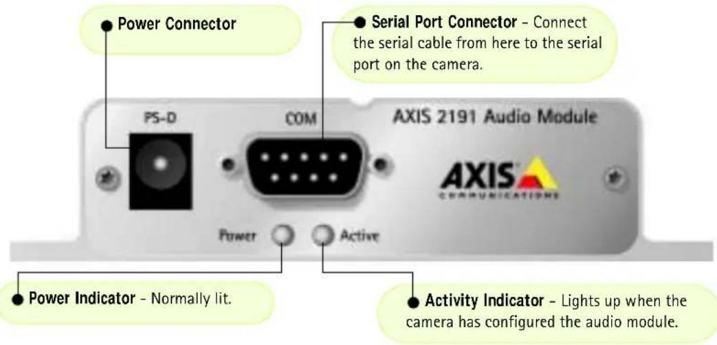
The AXIS 2191 Audio Module is an add-on device that provides audio capability to Axis network cameras. The module connects quickly and easily to the serial port of the camera and is configured and controlled via the camera's user interface. The AXIS 2191 is supplied separately.

flowchart
graph TD
    PC["PC"] -->|①| TCPIP["TCP/IP Network"]
    PC -->|②| PC2["PC"]
    PC -->|③| AXIS1["AXIS 2120/2420"]
    PC -->|④| AXIS3["AXIS 2191"]
    AXIS1 -->|③| AXIS4["AXIS 2191"]
    AXIS4 -->|④| AXIS5["AXIS 2100/2110"]
    AXIS5 -->|④| AXIS6["AXIS 2191"]
    AXIS6 -->|④| AXIS7["AXIS 2191"]
An Axis network camera (③ or ④) with an AXIS 2191Audio Module connected provides live audio and video to browser clients (① and ②) on the network.
Features and Functions
- Easy to install and use
- Runs on Ethernet LANs and/or the Internet
• Built-in omni-directional microphone - Compatible with most microphones and speakers (not included)
- External microphone via 3.5mm socket or Line-In via the terminal block
- Simple configuration and management via the network camera's administration pages
- Can be used in Full-Duplex, Half-Duplex or Simplex mode (see page 42)
- Push-to-talk button in client user interface in Half-Duplex or Simplex - Talk mode
• Fully adjustable input and output levels - M u t e f u n c t i o n
Legal Considerations
Video and audio surveillance may be prohibited by laws that vary from country to country. Please check the laws in your local region before using Axis network cameras or the AXIS 2191 Audio Module for surveillance purposes.
The Front Panel
The Rear Panel

Installing the Audio Module
Before installing the AXIS 2191 Audio Module, first install your network camera. Refer to the installation section of this manual. If you intend running the audio module in full-duplex mode, check that the sound card on your computer supports this.

Configuring the Audio Module
The network camera's administration pages provide all the tools required for successfully configuring the AXIS 2191. From the camera's home page, click on the link to Administration Tools. A new page containing the tools will open. To complete the configuration of your audio module, follow these instructions:

- From the Admin tools, click External Devices. Select the AXIS 2191 Audio Module as the device to use. Click Save.
Note: If you do not see External Devices, then your camera does not have the correct firmware installed and it must be upgraded. Please see Updating the Firmware, on page 63.
2.Under External Devices, click Audio. This opens the configuration page for the audio module (see illustration below). - Select the audio mode. This can be:
• Full-Duplex (Talk and Listen Simultaneously)
• Half-Duplex (Talk and Listen)
- Simplex - Talk
- Simplex - Listen
This selection will depend on your application. See page 42 for more information.
- Enter the number of clients that will be able to access the application at any one time. Use this setting to limit access if you only have limited bandwidth available.
- If you are using Half-Duplex mode, the Send option can be used to send audio from the client currently transmitting to all the other clients, and not just to the server end. Set to Yes to enable the function.
- When using Half-Duplex, the Push-To-Talk button will be visible. Select the mode to use for this button. Selecting Toggle means that when the button is pushed it will remain so until pushed again. Instant means that the button will remain active (pushed) until released.
- Adjust the Volume Out control until a satisfactory speaker level is heard. The Level Out LED can be used to check that there is audio being received. Note that both the control and the LED are on the audio module itself.
The configuration page for the AXIS 2191.

Using the Audio Module with Your Camera
Your audio module is now configured and ready for use with your network camera. Enter your camera's IP-address in Internet Explorer, or click Home on the camera's admin page. You should then see the control panel for the AXIS 2191 below the camera image. If no audio controls are visible, check that you have made the correct setting under External Devices.

Using the Different Audio Modes
Full-Duplex
Full-Duplex mode means that you can transmit and receive audio (talk and listen) at the same time, without having to use any of the controls. This is just like having a telephone conversation. The only controls you may wish to use are the mute checkboxes to turn off the sound, and the level sliders, to adjust the input/output levels. This mode requires a full-duplex sound card on your computer. If your available bandwidth is 0.2Mbit/s or less, it is recommended that you use Half-Duplex mode instead.
Half-Duplex
Half-Duplex mode also sends and receives audio in both directions, but only in one direction at a time. This means you must actively transmit with the help of the Push-to-Talk button. To speak, press the button (check that the microphone is not muted). When finished speaking, release the button. You will now be receiving audio from the other end of the connection. Note that the Push-to-Talk button can be configured for use in two different ways - Toggle or Instant. This is set in the camera's admin tools. Half-Duplex mode is best if you only have limited bandwidth available.
Simplex - Talk
Simplex - Talk mode means that only the web-client end of the connection can transmit audio (that is, to the AXIS 2191). This could be used, for example, to provide spoken instructions to a person seen in the network camera. This mode also requires you to use the Push-to-Talk button.
Simplex - Listen
Simplex - Listen mode can only receive audio from the AXIS 2191 to the web-client. This can be used in remote monitoring, web attractions etc., to provide live audio, as well as video, of a monitored situation.
Troubleshooting the Audio Module
Symptoms Possible causes Remedial actions
| No audio controls below camera image. | The AXIS 2191 is not selected as the external device. | In the camera's administration tools, click onExternal Devicesand select the AXIS 2191 Audio Module. |
| Wrong camera firmware. | Check the firmware in the camera by checking ifExternal Devicesappears in the camera's Administration Tools. If not, the camera does not have the correct firmware and it must be upgraded. | |
| No sound from the AXIS 2191 or from a PC trying to access a web page containing audio content. | Incorrect settings or faulty connections. | Check that:•soundcard, speakers and microphone are connected•the Mute button is not pressed•the Int/Ext switch for the input is in the correct position•the input and output levels are correct•all cabling is connected and all power switches are ON |
| No audio signal from PC to the AXIS 2191 when passing a proxy server. | The Post Content Length set in the proxy server is too low. | Set the value of the Post Content Length in your proxy server to 1MB or more. You may need to contact your system administrator to do this. |
| No full-duplex function. | Incorrect configuration. | Check the setting in the camera's administration tools. |
| Sound card does not support full-duplex. | For information on how to check if your sound card supports full-duplex, please visit www.axis.com and see the support section for Axis camera products. | |
| Poor performance. Too many users/clients connected. | Try limiting the number of clients allowed to connect. | |
| Low bandwidth. Reduce the available bandwidth by changing to a lower setting in the Available Bandwidth selector. Setting a lower bandwidth will reduce any break-up in the sound, but will also increase the transmission delay. | ||
| Whining or screeching sound from speakers (feedback). | Poor positioning of speakers and/or microphone. | If running in Full-Duplex mode, try switching to Half-Duplex mode. |
| Poor sound on headphones. | Incorrect connection. | Relocate the speakers or microphone so that they do not point towards each other, and/or lower the volume. |
| The Power indicator LED is not constantly lit. | Faulty power supply. Verify that you are using an AXIS PS-D power supply. | |
| The AXIS 2191 works locally, but not externally. | Firewall protection. Check the Default routers required. | Internet firewall with your system administrator. Check if you need to configure the default router settings. |
Note: If you still have a problem after reading this information, please contact your reseller, or visit www.axis.com and check the support section for Axis camera products.
Technical Specifications for the AXIS 2191
- Operating temperature: 40-105 °F (5-40°C).
• Humidity - 8-80% relative humidity. - EMC - :EN55024, EN55022, Class B and EN61000-3-3.
• EMC - FCC Class A of FCC Rules and Regulations part 15, subpart B. - EMC -
• Full-duplex audio: Audio data encoded in ADPCM format at 32kbps, 8 kHz sampling (G.721). Data is sent using HTTP.
• 9-pin D-SUB serial connector: RS-232.
• Power Input: Axis PS-D power supply. - Microphone Input: 1-50mVpp. PC type.
• Line Out: Unbalanced, 0.05-1.0Vpp
- Line Input: Balanced 0.05-1Vpp. Connect source ground to pin 2 and source signal to pin 1 if the source is unbalanced.
- Speaker Output: Balanced, 0.5W. Impedance 8-32 Ohms. Connect directly to speaker without capacitors.
• Alternative Power: 12-15VAC, min 10VA, or 15-20VDC, min 7W.
- Metrics: Height: 1.1" (27mm), Width: 4.4" (112mm), Length: 4.3" (110mm), Weight: 0.7lb (0.32kg).
• Maximum number of users: 10 (on local area network).
Connection Diagram

flowchart
graph TD
    A["STEREO EQUIPMENT"] --> B["LIME HOLT"]
    B --> C["Speaker"]
    C --> D["Power"]
    D --> E["VOLTAGE REGULATION"]
    E --> F["ALIRED CODE"]
    F --> G["ALIRED COMPRETENTS LPG"]
    G --> H["R8232"]
    I["MC IN"] --> J["2x 4.7K"]
    K["MULT IN MK"] --> L["2x 300K"]
    M["LINE OUT"] --> N["AC/DC"]
    O["POWER"] --> P["VOLTAGE REGULATION"]
    Q["+5V"] --> R["-5V"]
    S["+3.5V"] --> T["-3.5V"]
The Audio Module to Camera Serial Cable
The serial cable supplied with your AXIS 2191 is wired as shown in the table below:
Pinouts for the RS-232 Port
Audio Pin Pin Camera Signal

flowchart
graph TD
    IN1["IN 1 IN CD"] --> OUT3OUTTXD
    IN2["IN 2 IN RXD"] --> OUT3OUTTXD
    OUT3OUTTXD --> OUT4OUTDTR
    OUT4OUTDTR --> GND5GNDGND
    GND5GNDGND --> IN66INDSR
    IN66INDSR --> OUT7OUTRTS
    OUT7OUTRTS --> IN88INCTS
    IN88INCTS --> Unused99INRI
    GND5GNDGND --> OUT7OUTRTS
    OUT7OUTRTS --> OUT7OUTRTS
    OUT7OUTRTS --> GND5GNDGND
    GND5GNDGND --> OUT4OUTDTR
    OUT4OUTDTR --> OUT3OUTTXD
    OUT3OUTTXD --> OUT3OUTTXD
    OUT3OUTTXD --> OUT3OUTTXD
    OUT3OUTTXD --> OUT3OUTTXD
    OUT3OUTTXD --> OUT3OUTTXD
    OUT3OUTTXD --> OUT3OUTTXD
    OUT3OUTTXD --> OUT3OUTTXD
    OUT3OUTTXD --> OUT3OUTTXD
    OUT3OUTTXD --> OUT3OUTTXD
    GND5GNDGND --> OUT7OUTRTS
    OUT7OUTRTS --> OUT88INCTS
    OUT88INCTS --> GND5GNDGND
    GND5GNDGND --> OUT7OUTRTS
    GND5GNDGND --> OUT88INCTS
    GND5GNDGND --> OUT7OUTRTS
    GND5GNDGND --> OUT88INCTS
    GND5GNDGND --> OUT7OUTRTS
    GND5GNDGND --> OUT88INCTS
Appendix A - Troubleshooting
This appendix provides useful information to help you to resolve any difficulty you might have with your AXIS 2420. Symptoms, possible causes and remedial actions are provided in a quick reference table.
PINGing Your IP Address
By sending a packet to the specified address and waiting for a reply, the PING utility can determine whether a specific IP address is accessible. It also provides a particularly useful method for confirming addressing conflicts with your AXIS 2420 on the network.
Having disconnected your AXIS 2420, follow the instructions below in association with Symptoms, Possible Causes and Remedial Actions, on page 48, and run PING to troubleshoot TCP/IP problems on your network:
- Start a Command window.
- Type ping x.x.x.x, where x.x.x.x is the IP address of the AXIS 2420.
- If you receive the reply destination host unreachable, then the AXIS 2420 is not accessible on your subnet. You must obtain a new IP address and reinstall the unit.
- If this does not solve the problem, disconnect the AXIS 2420 from the network and run the PING command again. See the table below for an interpretation of the results.
PING Reply Interpretation and recommendation
| Reply from: bytes = 32; time = 10 ms.... | The IP address is already used and cannot be used again. You must obtain a new IP address. |
| Request timed out | This IP address is not used and is available for use with your AXIS 2420. If you set the IP address previously, the installation might not have been performed correctly. In this case, reinstall the unit. Also check all cabling. |
Symptoms, Possible Causes and Remedial Actions
Symptoms Possible causes Remedial actions
| The AXIS 2420 cannot be accessed from a Web browser. | The IP address is already being used by another device. | 1. Disconnect your AXIS 2420 from the network.2. Run the PING utility (as described in PINGing Your IP Address, on page 47) and follow the appropriate recommendations.Note: The assigned IP number can be assumed as being available for use if PING returns "request timed out" - in which case you should set the IP address again, power on the AXIS 2420 and then try accessing the unit again. |
| The IP address is located on a different subnet. | Run the PING utility (as described in PINGing Your IP Address, on page 47). If the utility returns no response or similar, then this diagnosis is probably correct.In Windows, check that the IP address for your AXIS 2420 is on the same subnet as your workstation. Exactly how this is done varies from one version of Windows to another. See Windows' help for more information.If your AXIS 2420 is on a different subnet than your workstation you will not be able to set the IP address from this workstation. Contact your network administrator. | |
| In Windows 95, the ARP table was empty when you tried to set the IP address. | In Windows 95, the ARP command cannot be used if you have an empty ARP table.Type arp -a to view the ARP table. If it is empty, you must ping an existing unit on your network before you can download the IP address to the AXIS 2420, using ARP.The AXIS IP Installer is a good alternative to ARP. | |
| The IP address has changed. Check that there is no DHCP or BOOTP server running on your network. | ||
| Possible problem with your proxy server. | Try disabling the proxy default in your browser. | |
| Other networking problems. Try replacing your network cable. | ||
| Test the network interface of the product by connecting a local computer to the unit, using a standard Crossover (hub-to-hub) Cable.If the above actions do not resolve the problem, the AXIS 2420 may be faulty. In this case, try to localize the problem by connecting the AXIS 2420 to the serial port of a local computer, using the supplied Null Modem Cable and report your findings to your local distributor. | ||
| The Power indicator is not constantly lit. | Faulty power supply. Verify that you are using an AXIS PS-D power supply. | |
Symptoms Possible causes Remedial actions
| The Network indicator displays red. | Faulty cabling. 1. To verify that the cable is functional, connect the cable to a known functioning device on the network and PING it from your workstation.2. If the cabling is OK and your network is reachable, you should receive a reply similar to this:Reply from: bytes = 32; time = 10 ms.... | |
| The Active and Network indicators are flashing every 0.5 seconds. | Hardware failure. Contact your Axis dealer. | |
| Your AXIS 2420 works locally, but not externally. | Firewall protection. Check the Internet firewall with your network administrator. | |
| Default routers required. Check if you need to configure the default router settings. | ||
| The Internet site is too heavily loaded. | Configure the AXIS 2420 to upload your video images to an FTP server or an ISP. | |
| No image using Refresh and/or Slow updating of images. | Multiple clients attempting to access the images, or complex images, i.e. containing a lot of contrast. | Try limiting the number of clients, or configure the AXIS 2420 to upload your video images to an FTP server or an ISP. Adjust the image settings to produce smaller files. |
| Cannot access the connected modem. | Faulty cabling. Check power supply, power cable and serial connection. | |
| A series of broad vertical white lines appears across the image. | The CCD sensor becomes overloaded when the light is too bright. This can happen e.g. with sunlight reflections. | If you are using the camera in strong light conditions, check that you are using a DC-Iris lens, and that the settings for the lens are correct, i.e. in the Image-Advanced settings, the exposure control should be set to DC-Iris.Note: damage caused to the AXIS 2420 through overexposure to direct sunlight or halogen light is not covered under the product warranty. |
| Bad focus. The focus has not been correctly adjusted. | Referring to the on-line help, adjust the White Balance setting and then try resetting the camera focus again using the Focus Assistant, as described in Lenses and Advanced Focusing, on page 54. | |
| No adaptor fitted with your C-type lens. | Fit the required adaptor. See page 54. | |
| Noisy images. Images may be noisy if you are using the AXIS 2420 in an environment with very low lighting. | To solve this problem, you need more light. The performance of the camera is best in 100 - 3.000 lux. Consider using a more sensitive lens (Lower F-number) if the lighting conditions within the installation area cannot be improved. | |
Symptoms Possible causes Remedial actions
| Bad quality images. The Display Properties are incorrectly configured for your computer screen. | Open the Display Properties for your screen and configure it to show at least 65000 colors, i.e. at least 16-bit.Note: Using only 16 or 256 colors on your screen will produce dithering artifacts in the image. |
| The camera is not focused correctly. | |
| No images available in your browser application. | ActiveX disabled. If you are using Microsoft Internet Explorer, ensure that ActiveX has not been disabled. |
| Java disabled. If using the Java Applet for viewing images, check that Java is enabled in your browser. |
Note: If you still have a problem after reading this information, please contact your reseller or check the FAQ on the Axis Website at www.axis.com.
Appendix B - Other IP Setup Methods
In addition to the ARP command (described earlier in the Installation section of this manual), you can alternatively set the IP address for your AXIS 2420 using any of the following methods - as appropriate for your operating system:
Method Operating Systems Refer to...
| AXIS IP Installer | Windows | Using the AXIS IP Installer, on page 52. |
| BOOTPRequiring a BOOTP daemon on your system, this method operates over the entire network. A request to an active daemon initiates a search of the boot table to find an entry matching the unit's Ethernet address. The daemon replies with the IP address for the device, if a match is found. | UNIX | |
| DHCPThis method should only be used if you know which IP address the DHCP server will give the camera, or if your version of DHCP can update a DNS server, which then allows you to access the camera using a name. | Most |
Notes:
- Do not use the default IP address featured in these examples when installing your AXIS 2420. If in doubt, consult your network administrator to obtain an unused IP address.
- Make sure the AXIS 2420 is powered up and attached to the network.
- Server Privileges: Although no special privileges are required for Windows 95/98/ME, you do need Administrator privileges for Windows NT/2000 and XP (Professional). UNIX systems require Root privileges.
Ethernet Address: The AXIS 2420 is pre-configured with a unique Ethernet Address based upon the serial number printed on the underside label of the unit; where the serial number typically follows the format 00-40-8c-xx-yy-zz. You must know the Ethernet address to complete the installation.
Using the AXIS IP Installer
AXIS IP Installer is a Windows program that is ideal for setting the IP addresses for multiple Axis networking products on your network. Also allowing you to access the home page of any Axis ThinServer device connected to your network, this freely distributed software is available for download from www.axis.com.
Installing the AXIS IP Installer:
- Download the latest version of the AXIS IP Installer and run the Setup_IPInstaller.exe program to start the installation.
- The AXIS IP Installer - Setup dialog is displayed on the screen.
- Follow the instructions as they appear on the screen.
- Click Finish to complete the installation.
Setting the IP Address with AXIS IP Installer:
- Run the AXIS IP Installer from the Start menu. The following window will appear:
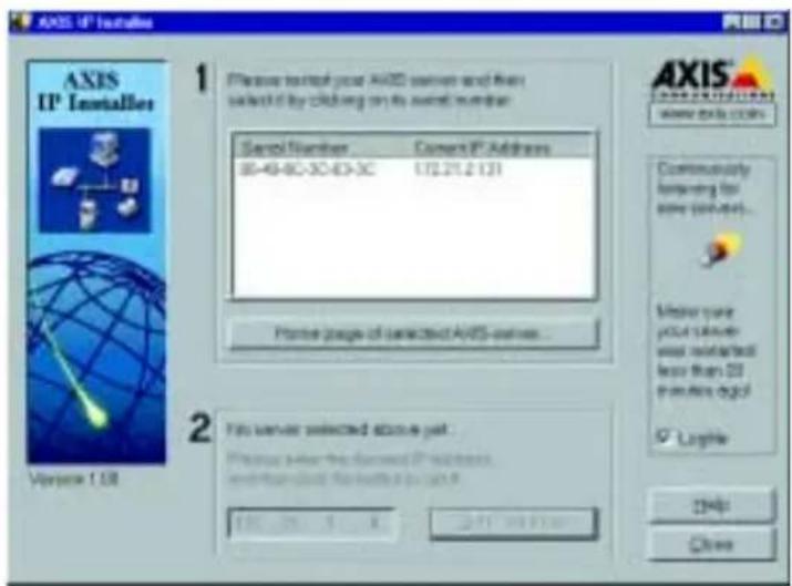
- Restart your AXIS 2420.
- Select the serial number of your AXIS 2420 in the list. The serial number is identical to the unit's Ethernet address.
- Enter the IP address. Click Set IP address. The IP address will now be set.
- To access the home page of the AXIS 2420, click Home page of selected Axis-server... You can now configure the AXIS 2420 according to your requirements.
- Click OK to exit the program.
For more help during the installation of the IP address, click Help or press the F1 key.
Notes for Macintosh Users
The AXIS 2420 supports TCP/IP over Ethernet, or PPP Modem dial-up. You must use TCP/IP on your Macintosh network, as there is no support for AppleTalk.
When using the AXIS 2420 on a Macintosh, please observe the following points:
- The camera has a default IP address of 192.36.253.80.
- Assign a temporary IP address to a Mac workstation in the same subnet (e.g. 192.36.253.81) and then connect to the camera.
- Run the Installation wizard and set the desired IP address for the camera.
- Reset the correct IP address for the Macintosh workstation.
- Changing the IP address for a Macintosh does not require a reboot.
Currently there are limitations in the ActiveX Support in Internet Explorer running on the Macintosh. This results in problems when viewing live moving images. The recommended solution for viewing Axis cameras on the Macintosh is to use Netscape.
Appendix C - Lenses and Advanced Focusing
Your camera was supplied either without a lens (AXIS 2420), or with a DC-Iris lens (AXIS 2420 W/Lens). Either model can be fitted with any standard CS/C lens. The DC-Iris support included with the AXIS 2420 will drive any standard DC-Iris lens.
Fitting a Lens
Note: The AXIS 2420 is equipped with a CS-mount, so any standard CS lens can be fitted directly. To mount a C-type lens, a CS-C adapter must also be used. The adapter effectively moves the lens 5mm away from the camera's CCD.
Follow the instructions below to fit any C or CS type lens:
- C-lens only: Attach the new lens to a CS-C Adapter.
- Screw the lens onto the AXIS 2420. If applicable, adjust the iris according to the prevailing light conditions.
- Referring to Focusing Procedure, on page 56, adjust the camera focus.
- Adjust the DC-Iris settings. See page 57.
- Refresh your browser and check the results from the camera's Home Page.
Caution!
Exposing your camera to bright sunlight may cause permanent damage to the CCD if you:
- use a non-DC Iris lens, or
- select anything other than DC-Iris in the Exposure Control settings of the Image - Advanced page.
Axis consequently advises extreme caution when fitting a lens to your AXIS 2420 and/or when using the Image - Advanced settings. Damage caused to the AXIS 2420 through overexposure to direct sunlight or halogen light is not covered under the product warranty.
Direct Focusing in Your Browser
The AXIS 2420 is easily targeted for different applications. With your video stream displayed in a browser, simply adjust the camera focus ring until you are satisfied with the focus.
However, for remote installations - where you are unable to view your video images directly in a browser - you can achieve a good level of camera focus by using the Focus Assistant, described below.
Notes:
- The text information printed on the lens assembly will clearly define the focusing polarity (F, , and N) for the focus ring supplied with your unit. The camera focus is adjusted for either Far-focus (F, ) or Near-focus (N) by rotating the focus ring in the appropriate direction.
- The lens rotates on a screw fitting and can be completely removed. If you need to remove the lens, take care not to let any dust enter the lens or the camera window as this can adversely affect the quality of your live images.
Important!
The illustration below is displayed as an example of a commonly available lens type, but is NOT typical for all lens types.
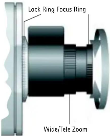
Using The Focus Assistant
Important!
As an alternative to the procedures described here, you can also enable and use the Focus Assistant directly from the Administration Tools. For more information on this, please refer to the on-line help.
Enabled manually using the Control Button (or via the administration Web pages), the Focus Assistant works in conjunction with the Status Indicator to provide an onboard visual display for focusing your camera. With the Focus Assistant enabled, the Status Indicator displays Green when the camera is focused - which means you can conveniently focus the AXIS 2420 without having to monitor the images in a desktop browser.
Focusing Quality
The table below show the full range of colors displayed by the Status Indicator when the Focus Assistant is enabled; where each color represents a predefined level of focus:
Color Level of Focus (%) Focus Quality
| Red 0 - 60 Poor | ||
| Yellow 60 - 80 Reasonable | ||
| Green 80 - 100 Good |
Plane of Focus
The lens has rotational focus control that allows the focal length of the lens to be adjusted manually. Depending on the chosen physical location for your camera, it is likely that several planes of focus will exist throughout the full focusing depth of the unit; consequently, the Status Indicator is likely to display green - indicating a good level of focus - several times throughout the full travel of the lens assembly.
Focusing Procedure
Before you begin:
For the focusing algorithm to work efficiently, always ensure that there is minimal movement in the camera's field of view when focusing, as described below.
With reference to the accompanying illustrations, follow the instructions below to achieve a good basic level of focus under stable conditions:
Important!
Do not press the Control Button for at least 10 seconds after powering up the unit, as this will cause the AXIS 2420 to return to its factory default settings.
- Power up the AXIS 2420 and then wait at least 10 seconds.
- Turn the lens to its extreme Far-focus (F, ) position.
- Enable the Focus Assistant. Using a suitably pointed object, press and continue to hold the Control Button - until the Status Indicator flashes Yellow. The Focus Assistant is now enabled with the Status Indicator set to Focus Mode. The AXIS 2420 now initiates a focusing algorithm to regularly calculate the quality of focus.
- In order for the Focus Assistant to access the full focusing range for your application environment, turn the lens slowly to its extreme Near-focus (N) position.

Control Button
- Finally, turn the lens slowly towards the Far-focus (F, ) position, until the Status Indicator displays Green; that is, until a Good level of focus is achieved.
Notes:
- A Good level of focus is normally achievable throughout several planes within the focusing range of the camera.
- The Status Indicator displays Green to indicate a Good level of focus at 80% of optimum focus.
-
Since optimum focusing is dependent upon the camera's field of view, it is important to scan the focusing plane from the furthest to the closest perspectives before attempting any fine-tuning.
-
Return to your browser and review the picture quality. Repeat step 5 only if you consider the focal distance too distant - until you are satisfied with both the focal-distance and focus-quality.
- To exit the Focus Assistant: press and hold the Control button - until the Status Indicator flashes Yellow. The Status Indicator displays Green when the Focus Assistant is closed.
Adjusting the DC-Iris Settings
The DC-Iris settings must be adjusted to meet the requirements of the lens you intend to use. You will need to modify the Exposure Control and other related settings for your camera, from the Image-Advanced page.
Use the information presented in the following tables to choose the appropriate settings for your lens type.
Caution!
Exposing your camera to bright sunlight may cause permanent damage to the CCD if you:
- install and use a non-DC Iris lens with the product, or
- select anything other than DC-Iris in the Exposure Control settings of the Image - Advanced page.
Axis consequently advises extreme caution when changing the lens and/or when using the Advanced settings. Damage caused to the AXIS 2420 through overexposure to direct sunlight or halogen light is not covered under the product warranty.
Exposure Control Overview
The table below provides a summary of the Exposure Control settings in the Image - Advanced page. Select the parameters for your lens type and product application.
Lens Options Description
| DC-Iris | The DC-Iris setting is the standard factory default setting found on the Image-Advanced page. It allows the user to manually specify the exposure, shutter speed, gain, and ALC levels. |
| Non-DC-Iris - Manual | Choose this setting if you have fitted a non-DC-Iris lens to your AXIS 2420, but wish to adjust the shutter speed and gain manually. |
| Non-DC-Iris - Shutter | Choose this setting if you have fitted a non-DC-Iris lens to your AXIS 2420 but wish to adjust the shutter speed manually. |
| Non-DC-Iris - Auto | Choose this setting if you have fitted a non-DC-Iris lens to your AXIS 2420 and would like the shutter speed and gain to be adjusted automatically. |
Other Advanced Parameters
Lens Options Description
| Shutter Speed | Derived from the shutter speed on a normal camera, this parameter defines the exposure period for each image. Use a high shutter speed only if your image subject is expected to be moving quickly; otherwise, a slower speed will normally suffice. |
| Sharpness | Defines a level of differentiation between light and dark areas within the image. Corresponding higher levels of sharpness provide for sharper images, but also cause the image compression to be more complex. Consequently, the file size of a sharp image can be significantly greater than an image that is less sharp. |
| Gain | Adjust the gain to suit the average level of light at your point of installation. The AXIS 2420 should be set to a corresponding higher level of Gain if your camera is normally monitoring an area at night, or is situated in a dark room or cupboard. |
| ALC Level | This defines how acutely the lens reacts to a single light source within the image. For example, with the ALC level set at a higher level, the headlights from a car will generally cause the calculated average level of light to increase, and subsequently result in a compensated image that is usually much darker.Adjusting the ALC to a lower level reduces the sensitivity of the lens to single light sources within the image. |
Adjusting the Back Focus
Your AXIS 2420 is supplied with the back focus roughly set to accommodate a reasonable level of focus throughout the complete focusing range. However, if you are dissatisfied with the quality of focusing at a specific plane (or at several planes) within the focusing range, you may need to make some fine adjustments to the back focusing of the lens. This is performed by adjusting the focus and zoom rings of the camera lens, as described below:
Procedure
- With the Focus Ring set to the Far-focus (F, ∞) position, aim the camera at a subject over 30 metres away.
- Set the lens assembly to wide angle, and adjust the back focus by loosening the Lock Ring and then turning the lens assembly. Continue to turn the lens assembly until you achieve optimum image clarity
- Check that you obtain sharp pictures at various zoom grades and various distances.
Note:
If possible, it is better to perform this adjustment in low light conditions, or with a filter covering the front optic. This will ensure the iris is fully open to give the smallest depth of field, and therefore the best result.
Appendix D - Customizing Your Camera
Modifying the File System
The Linux-based operating system and flash memory file system make it possible for advanced users and application developers to customize the AXIS 2420 by adding additional files to the read-write area of the flash memory.
Important!
- Modification of the flash file system is NOT supported by Axis. In practice, this means that Axis will not answer questions relating to custom script or Web page development, but merely wishes to inform potential application developers of the possibilities afforded by the Linux-based file structure of the AXIS 2420.
- When attempting to modify the product, you may inadvertently create a problem that will require you to return the AXIS 2420 to its factory default settings. At worst, you may even cause permanent damage to the unit that renders it unusable. Consequently, Axis strongly recommends that inexperienced users DO NOT modify the file system.
Although modification of the file system is not supported, the Axis web at www.axis.com does maintain various documents designed to assist third-party development. These include detailed information such as:
- The Axis Camera API, HTTP-Interface Specification
- A description of the reduced PHP3 scripting language
Configuration using FTP
As an alternative to configuring the AXIS 2420 from a browser, the configuration parameters of your camera can be modified using the File Transfer Protocol (FTP).
FTP is supported by most operating environments and is a useful method for quickly uploading standard pre-configurations to one or more cameras.
Custom Web Pages
The AXIS 2420 contains a re-writable flash memory file system that allows some directories and files to be changed by the root user, using FTP. This strictly non-supported product functionality makes it possible for advanced users and application developers to add their own Web pages, scripts, and other files to the Axis product.
Customizing Procedures
The existing Administration pages are stored in a compressed read-only area of the file system. If you intend to try changing these pages, you must adhere strictly to the instructions provided here and ensure that you DO NOT inadvertently change any files other than those featured in this section. Failure to comply with this notice may render your product unusable.
All files stored in the /etc/httpd/html directory are available through the product Web server in the virtual directory /local/. The URL to resident pages in the /etc/httpd/html directory is http://IP/local/
You can change the html files as and when you like, but remember that the available flash memory is limited. The number of times the memory can be written to is approximately 1 million.
Creating a New Home Page
Having created and stored your new custom Web pages in product memory, you then proceed to assign one of these pages as your default Home page in the AXIS 2420, as described below:
Caution!
Adding a new Web page to your AXIS 2420 is not something that should be undertaken lightly. Remember: Axis does not support the personalization of product Web pages and strongly recommends that inexperienced users DO NOT perform such modifications.
- Start a new FTP session to the AXIS 2420, by entering:
ftp <camera ip address>
- Type bin
- Navigate your way to the appropriate directory, entering:
cd /etc/httpd/conf/
- Fetch the boa.conf file, by typing:
get boa.conf
- Edit boa.conf and add the following lines to the end of the file:
Alias /index.html /etc/httpd/html/index.html
Alias / /etc/httpd/html
This will create an alias to your own "homemade" index.html file stored in the /etc/httpd/html/ directory and redirect access to it. Replace the edited boa.conf in the camera, by using the put command.
- Restart the camera.
Note: As an alternative to the above, you might like to edit the line starting with Document Root so that it points directly to the local directory. However, after doing this you will then be unable to access the original Home pages - so be warned!
- After making these changes, you will not be able to automatically access the default index page. Instead you must type in the complete URL to access it:
http://IP-address/view/index.html
Appendix E - Updating the Firmware
The AXIS 2420 camera firmware is stored in Flash memory. This memory is provided by a silicon chip that, just like any other ROM device, retains data content even after power is removed. Flash memory is unique because it allows its data to be erased and re-written. This means that you can install firmware updates for your AXIS 2420 as soon as they become available - without having to replace any parts. New firmware can be simply loaded into the AXIS 2420 over the network.
Obtaining Updated Firmware
The latest version of the AXIS 2420 camera firmware is available free of charge from the Axis website at www.axis.com or from your local distributor.
Upgrading
The AXIS 2420 Flash memory is upgraded over the network using FTP. See the detailed instructions supplied with each new firmware release.
Important!
- Always read the instructions available with each new release, prior to upgrading.
- Upgrading normally takes at least 30 seconds and up to 10 minutes, although it can take longer. After starting the process, you should always wait at least 20 minutes before power cycling the AXIS 2420 - even if you suspect the upgrade procedure has failed.
- In controlled environments, flash memory upgrades provide a very safe method for updating firmware. However, flash products can become damaged if the upgrade operation is not performed correctly. Your dealer reserves the right to charge for any repair attributable to faulty upgrading by the user.
Appendix F - The Unit Connectors
This section provides an overview of the product connectors, namely:
- 1 x RS-232 Serial Connector
- 2 × I/O Connectors (I/O-A and I/O-B)
- 1 x DC-Iris Connector
- 1 x BNC Video Output
- 1 x Ethernet network connector (RJ-45)
The RS-232 Serial Connector
In the absence of a local network connection, a single 9-pin D-sub connector provides a dedicated physical interface for connecting a modem or computer to the AXIS 2420. This RS-232 interface supports modem speeds of up to 115kbps and effectively allows the AXIS 2420 to operate as a standalone unit independent of any computer network. So, when a local network connection is unavailable at the point of installation, you can simply connect your PC to this connector and use the supplied Null Modem Cable to initially configure your product. If you intend using the AXIS 2191 Audio Module with your network camera, then this is the connector to use.
Note: The Axis Camera Division maintains a list of all supported modems. Please visit our Website at www.axis.com for this and other late information on our products.
Pinout Information
A diagram of the RS-232 connector, complete with pinout information, is shown below.
Pin Function
| 1 CD (Carrier Detect) |
| 2 RXD (Receive Data) |
| 3 TXD (Transmit Data) |
| 4 DTR (Data Terminal Ready) |
| 5 GND (Ground) |
| 6 DSR (Data Signal Ready) |
| 7 RTS (Return To Send) |
| 8 CTS (Clear To Send) |
| 9 RI (Ring Indicator) |

The I/O-A Connector
Used for connecting external alarm devices and triggering images for alarm-based events, the 4-pole I/O-A Connector provides the interface for a single digital input. Connected to a switch or other external security device, an image is recorded every time the switch is activated. It also provides an auxiliary DC power input or output for the AXIS 2420.
Pinout Information
Pin Function
4 Digital Input - Photocoupled Cathode (-) As below.
3 Digital Input - Photocoupled Anode (+)
Electrically isolated from the chassis and connectors, this input can be supplied from an external DC voltage or the DC power input/output on pin 2.
2 Positive Connection for DC power input or output:
Electrically in parallel with the derived DC power for the unit, this pin can be used as an input or output. As an input it can be used for remote applications to supply the AXIS 2420 via an external direct current source; for example, a 9-15V DC battery supply. Used as an output, it can drive the photocoupled input or other equipment; such as a thermal sensor. The output voltage level is dependent upon the input voltage to the unit. A maximum current of 50mA can be sourced from the DC output.
1 Common Ground

flowchart
graph TD
    A["1"] --> B["2"]
    B --> C["3"]
    C --> D["4"]
Schematic Diagram
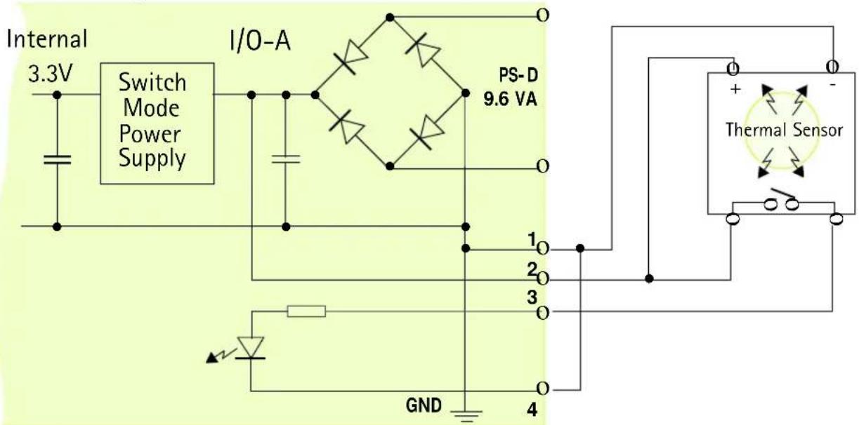
Caution!
Pin 2 is connected to the derived DC power for the unit, and can be used as an external power feed for external equipment, such as an Infrared sensor. When connecting other equipment using this connector, the maximum current of 50mA must be strictly observed. Failure to do this may cause a loss of power to the unit and even damage it.
The I/O-B Connector
The 4-pole I/O-B connector provides a digital relay switch for the control of external surveillance devices and services; such as, lighting, annunciators, audible alarms, etc. It is also an RS-485/422 port for the control of pan tilt devices, etc. A pinout table is provided below.
Pinout Information
Pin Function
1 Relay switch - pole 1. Electrically isolated from chassis and connectors.
2 Relay switch - pole 2. Electrically isolated from chassis and connectors.
3 RS-485/422 - B (inverting)
A half-duplex RS-485/422 interface for controlling auxiliary equipment.
4 RS-485/422 - A (non-inverting)

flowchart
graph TD
    A["1"] --> B["2"]
    B --> C["3"]
    C --> D["4"]
Schematic diagram - showing possible application

The DC-Iris Connector
The AXIS 2420 can be used with any standard C/CS lens. With full support for standard DC-Iris lenses, the camera will automatically regulate the amount of light entering the camera.
The DC-Iris Connector provides the power and control signalling required for a DC-Iris lens. The connector is located on the rear panel and the pinout for the connector is shown below.
Pin Function
1 Control and detection (-)
2 Control and detection (+)
3 Motor (+)
4 Motor (-)

Socket on rear of camera

Soldering side of connector
The BNC Video Output
The BNC Video Output can be used for connecting the AXIS 2420 to a traditional analog CCTV system or to a VCR. This output can be used independently of the Ethernet network connector and both can be used at the same time. The output conforms to 1.0V (p-p) 75 Ohms, sync negative.
The Ethernet Network Connector
The RJ-45 network connector is used to connect the AXIS 2420 to a 10/100Mbit Ethernet network running TCP/IP.
Control and Monitoring
You can enable IO Status to display ON/OFF buttons for driving the Digital Output from the Layout section of the Administration Tools on the Home Page of the AXIS 2420.
By entering http requests in your browser's URL field, you can:
• drive the relay output high or low
• monitor the status of the digital input
This requires you to have root access to the AXIS 2420 and consequently, to supply a user name and password. Login as root and supply the root password (default = pass).
Tip!
Developers wishing to create applications incorporating sophisticated alarm conditioning using the relay output and digital input are encouraged to read the Camera API, HTTP-Interface Specification, available from the Axis Web at www.axis.com.
Relay Output
You can use the supported relay output to directly drive a maximum load of 24V AC/DC at 100mA. By connecting additional relay circuitry, it can also drive heavier loads.
The output relay is controlled using http requests, as defined in the following examples:
Example 1: - Set output 1 ON.
http://myserver/axis-cgi/io/output.cgi?action=1:/
Example 2: - Set two 300ms pulses with 500ms delay between the pulses on output 1.
http://myserver/axis-cgi/io/output.cgi?action=1:/300\500/300\
Example 3: - Wait 1 second before setting output 1 ON.
http://myserver/axis-cgi/io/output.cgi?action=1:1000/
Digital Input
The digital input, programmed using the Application Wizard, allows the AXIS 2420 to be configured for time and alarm based image recording. For example, by connecting a motion detector to the digital input, it is a relatively simple procedure to send a single image (or video stream) to a remote imaging library each time the detector is activated.
Querying the Status of the Digital Input
The status of the digital input can be queried in exactly the same way as the relay output. Simply enter the following URL to query the status of the digital input:
Example: - Monitor data on port 1
http://myserver/axis-cgi/io/input.cgi?check=1
The AXIS 2420 then displays the status of the input, as follows:
Input 1 = 0
Appendix G - High-Speed Services
The AXIS 2420 is designed with high-speed Internet services foremost in mind, and you will experience the full performance of your AXIS 2420 if you are fortunate enough to have xDSL or a cable modem connection. However, as most high-speed Internet services only provide you with one external IP address, there are some practical issues that should be considered when developing your application. This section discusses some of these issues.
Available IP Addresses
Ideally your ISP (Internet Service Provider) should supply you with several external, static IP addresses - in which case you can assign any one of these to your AXIS 2420 to make it fully accessible over the internet. If your ISP supplies you with only one IP number - which is usually the case - then this IP number is normally assigned to your PC. If your ISP is unable to provide you with an additional IP number, you still have a number of other options that you may like to consider, including:
Windows 2000 NAT-feature (Network Address Translation):
Utilize the NAT feature in Windows 2000 to allow multiple Ethernet cards in your PC. You then use one port for the Internet and the other for your internal network. Using this solution, you can let your AXIS 2420 upload image streams to your ISP's external Web server.
Routers and Firewalls
Another ideal solution is to use one of several small routers/firewalls that are currently available on the market. These provide the necessary NAT functionality and allow complete independence for your PC, which can be switched off or rebooted without affecting the image transmission from your AXIS 2420.
WinGate Server Software:
Running on a single Windows computer, this software allows multiple users simultaneous access to the Internet through a single connection; be it modem, ISDN or high speed line, such as xDSL or cable modem connection. You can thus effectively share a single Internet connection with almost any type of client computer running TCP/IP.
For more advanced users, the WinGate 3.0 Standard and Pro versions allow the administrator to change the IP bindings so that external requests may be routed specifically to your AXIS 2420 - running behind the WinGate software.
Appendix H - Technical Specifications
System Requirements - The AXIS 2420 uses the standard Internet TCP/IP suite of protocols and can be used with most operating systems: Windows, Linux, UNIX, Mac and several others. The only software required is Microsoft Internet Explorer 4.x/5.x or Netscape 4.x.
Installation - Physical network connection using RJ-45 twisted pair cable, or remote connection using any standard serial modem.
Management - Remote configuration and status using Web-based Administration Tools.
Image Features - Time/date stamp, text overlay, variable size, color CGI control, and in-picture motion detection.
Picture Resolution - CIF=352x288 and 4CIF=704x576 (PAL), 352x240 and 704x480 (NTSC).
Networking - 10baseT Ethernet or 100baseTX Fast Ethernet, TCP/IP, HTTP, FTP, SMTP, NTP, ARP and BOOTP.
I/O-A Connector - One optical-isolated alarm input. Used for connecting external alarm devices, e.g. temperature sensors and switches.
I/O-B Connector - One digital relay switch output (max 24V, 0.1A), software controlled. Used for control of external surveillance devices and services; such as, lighting, annunciators, audible alarms, etc. One RS-485/422 port for connecting PTZ devices, etc.
Pre/Post Alarm Buffer - Up to 4 MBytes memory available for pre/post alarm image storage.
RS-232 Connector - Single 9-pin D-SUB RS-232 connector, max 115 kbps, half-duplex. For connecting a modem or a PTZ device.
Security - Multi-user password protection.
Operating Conditions: - Temp: 41-122°F (5-50°C), Humidity: 8-80% RHG.
Approvals EMC
- This equipment complies with the requirements in Part 15, Subpart B of FCC Rules for Class A computing devices.
• EN5022:1994 Class B
• C-Tick (Australia)
Approvals Safety
• EN60950, UL, CSA
Metrics: - Height: 2.24" (57mm), Width: 3.39" (86mm), Length: 5.43" (138mm).
Hardware - ARTPEC-1 compression chip; ETRAX-100LX (32-bit RISC, 100 MIPS CPU), 16 Mbytes DRAM, 4 Mbytes FLASH PROM.
Lens (AXIS 2420 W/Lens only) - Varifocal DC Iris lens with CS Mount, manual zoom, variable focus, and exposure control. Variable shutter speeds between 1/50 - 1/10000 (PAL) and 1/60 - 1/10000 (NTSC).
Electronic Shutter - Full DC-iris support and variable shutter speeds 1/50-1/10000 (PAL) and 1/60-1/10000 (NTSC).
Illumination - 1 to 20000 Lux, with F1.0 DC-Iris lens.
Power - External power supply 12V AC, 9.6 VA (PS-D, included), 9-15V AC, min 10VA, or 9-15V DC, min 7W.
Complimentary Software - AXIS IP Installer for quick installation of multiple units. AXIS Camera Control (Axis' ActiveX component software required for Microsoft Internet Explorer).
Networking Technology - Incorporating Axis ThinServer Technology, the AXIS 2420 is a truly embedded system and self-contained product, based on the Linux operating system and including the most popular network protocols and Web management tools. The hardware is built on Axis' own ETRAX-100LX 32-bit RISC processor, which is streamlined and optimized for device connectivity to networks, independent of any other network resource. The AXIS 2420 uses the industry's first dedicated network digital video surveillance compression chip - the AXIS ARTPEC-1.
Compression and Performance - The AXIS 2420 delivers Motion-JPEG images at up to 25/30 (PAL/NTSC) images per second, as well as single JPEG images that feature user-controlled compression levels. See also Picture frequency for Networking Applications, on page 20.
All specifications are subject to change without prior notice.
natural_image
Front view of a computer interface with ports and connectors (no visible text or symbols)
natural_image
Exterior view of a silver security camera with dual lenses (no visible text or symbols)

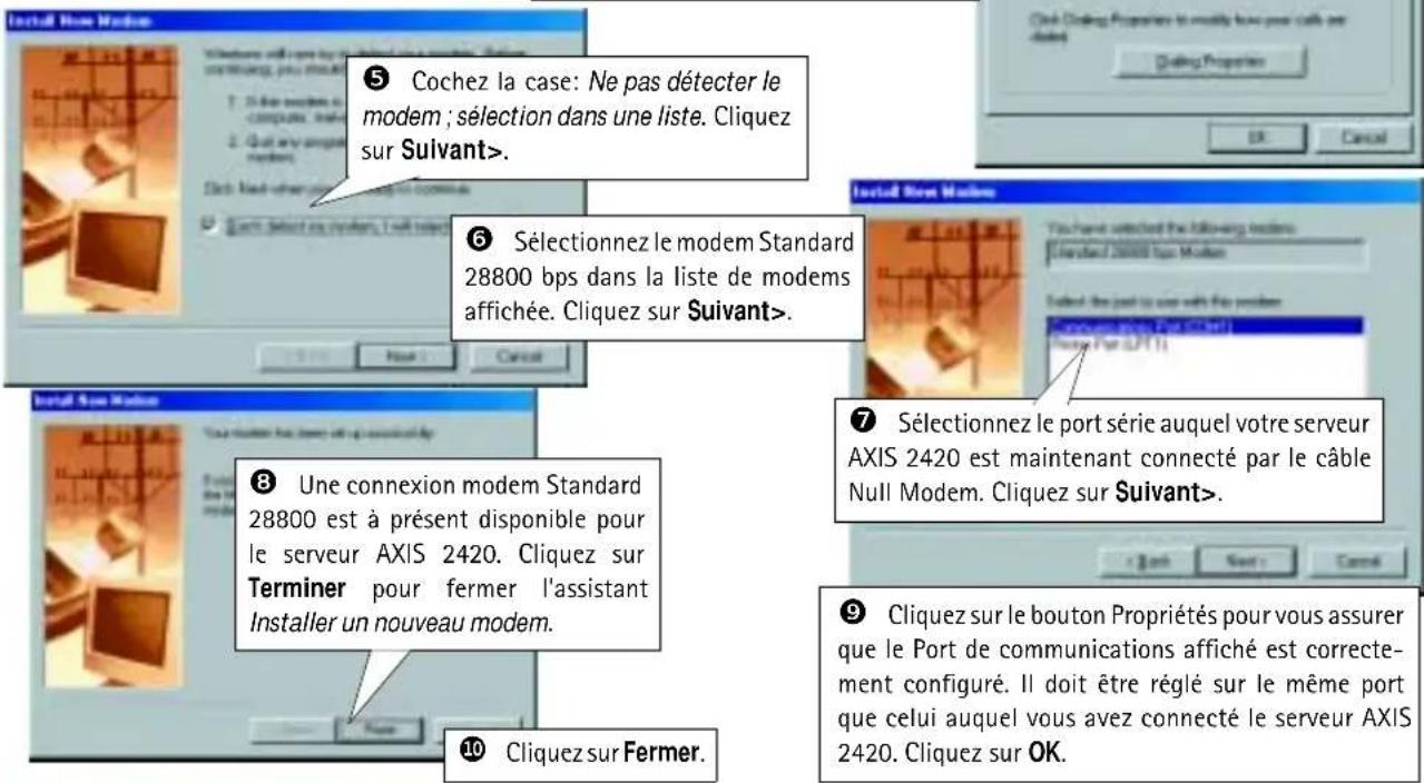
natural_image
Exterior view of a white Cartesian camera with visible lens and control buttons (no text or symbols on body)Bouton de contrôle
Admin - access rights 23
Administration Tools 20
Advanced lens parameters 58
Anonymous user access 23
AppleTalk 53
Application Wizard 19
Applications 31
ARP 48
ARTPEC-1 7
Audio Configuration 41
AXIS IP Installer 51
B
Back focus 59
BNC Video Output 67
Boa Web server 8
BOOTP 51
C
CCD 9
CGI scripts 6
COM-Ports 25
Compression 7
Configuring your camera 18
Connecting PTZ Devices 27
Connectors 64
Control Button 9
Creating a Motion Detection Window 24
CS Mount Ring 9
D
DC-Iris Connector 10, 67
DC-Iris Settings 57
DHCP 22
Dial-in - access rights 23
Dial-up Networking 15
Digital Input 68
Direct Focusing 55
E
Ethernet 5
Ethernet address 51
ETRAX 100 LX 7
Exposure Control 58
F
Factory Default Settings 30
Fast Ethernet 5
Firewalls 69
Firmware update 63
Fitting a new lens 54
Focus Assistant 55
Focus Quality 55
Focus Ring 55
Front Panel 9
H
Hardware Inventory 11
|
I/O-A Connector 10, 65
I/O-B Connector 10, 66
Image compression 32
Installation 12
The AXIS 2191 Audio Module 40
Installation Wizard 19
IP address 48, 69
IP setup methods 51
ISP settings 26
L
Lenses 54
Linux 8
Lock Ring 9, 55
M
Macintosh users 53
Modem installation 14
Modems 25
AXIS 2420 User's Manual Index
Motion Detection 24
Mounting the unit 11
N
Network Address Translation (NAT) 69
Network Connector 10
Network Indicator 10
Network installation 12
Null Modem Cable 14
0
Other IP setup methods 51
P
Pan/Tilt/Zoom devices 25, 27
Picture frequency 32
PING the IP Address 47
Plane of Focus 56
Power Indicator 10
Power indicator 44
Power supply connector 10
PPP 8
Preset positions 29
Problems 47
Proprietary ISP Dial-up Protocols 34
R
Rear Panel 10
Relay output 68
Routers 69
RS-232 connector 10, 64
RS-232 port - using a modem 25
S
Security 23
Serial connector 64
Serial number 9
SMTP 6
Specifications 70
Status Indicator 9, 55
T
Technical specifications 70
AXIS 2191 45
Triggering images 65, 68
Troubleshooting 47
AXIS 2191 Audio Module 44
U
Updating the software 63
Uploading Images 35
Uploading Pre and/or Post Alarm Images 36
V
Verifying the installation 13
Video Out Connector 10
View - access rights 23
Viewing live Images in a Browser 37
W
Wide/Tele Zoom 55
WinGate 69
Wizards 18
- AXIS 2420 AXIS 2420 W/Lens Network Camera
- About This Document
- Safety Notices
- Legal Considerations
- Electromagnetic Compatibility (EMC)
- Liability
- Trademark Acknowledgments
- Support Services
- Table of Contents
- An Introduction to the AXIS 2420. 5
- Physical Description 9
- Checking The Hardware Inventory.... 11
- Installing on a Network. 12
- Installing via a Modem 14
- Focusing Your Camera.... 17
- Configuring Your Camera 18
- The Factory Default Settings 30
- Choosing Your Application 31
- The AXIS 2191 Audio Module 38
- Appendix A - Troubleshooting. 47
- Appendix B - Other IP Setup Methods 51
- Appendix C - Lenses and Advanced Focusing 54
- Appendix D - Customizing Your Camera 60
- Appendix E - Updating the Firmware 63
- Appendix F - The Unit Connectors. 64
- Appendix G - High-Speed Services 69
- Appendix H - Technical Specifications. 70
- Deutsch
- Product Overview
- Features and Benefits
- Physical Description
- Front Panel
- Important!
- Rear Panel
- Mounting the AXIS 2420
- Checking The Hardware Inventory
- Installing on a Network
- Verifying and Completing the Installation From Your Browser
- Installing via a Modem
- Connecting Your Computer Using the Null Modem Cable
- Creating a Dial-Up Networking Connection
- Refining the Dial-Up Networking Properties
- Initiating the Dial-Up Connection
- Verifying the Modem Connection and Completing the Installation
- Focusing Your Camera
- Configuring Your Camera
- Before you begin:
- Configuration Using the Wizards
- The Installation Wizard
- Using the Installation Wizard
- The Application Wizard
- Using the Application Wizard
- The Administration Tools
- Accessing the Tools
- Example!
- Administration Tools Overview
- DHCP
- System Security
- Notes:
- User Access Rights
- Motion Detection
- Creating a Motion Detection Window
- COM-Ports, Modems and Pan-Tilt-Zoom Devices
- Setting the RS-232 Port for use with a Modem
- Modem
- ISP
- Using Pan-Tilt-Zoom Devices
- Connecting PTZ Devices
- Installation Procedure
- Preset Positions
- The Factory Default Settings
- Choosing Your Application
- Networking Applications
- Note:
- Picture frequency for Networking Applications
- Image Compression Ratios
- Modem Applications
- Configuration
- Picture Frequency for Modem Applications
- Proprietary ISP Dial-up Protocols
- Sequentially Uploading Images to an FTP Server/ISP
- Installation and Configuration Overview
- Uploading Pre and/or Post Alarm Images to an FTP server/ISP
- Viewing live Images in a Browser
- The AXIS 2191 Audio Module
- Features and Functions
- Installing the Audio Module
- Configuring the Audio Module
- Using the Audio Module with Your Camera
- Using the Different Audio Modes
- Full-Duplex
- Half-Duplex
- Simplex - Talk
- Simplex - Listen
- Troubleshooting the Audio Module
- Technical Specifications for the AXIS 2191
- The Audio Module to Camera Serial Cable
- Appendix A - Troubleshooting
- PINGing Your IP Address
- Symptoms, Possible Causes and Remedial Actions
- Appendix B - Other IP Setup Methods
- Using the AXIS IP Installer
- Installing the AXIS IP Installer:
- Setting the IP Address with AXIS IP Installer:
- Notes for Macintosh Users
- Appendix C - Lenses and Advanced Focusing
- Fitting a Lens
- Caution!
- Direct Focusing in Your Browser
- Using The Focus Assistant
- Focusing Quality
- Plane of Focus
- Focusing Procedure
- Adjusting the DC-Iris Settings
- Exposure Control Overview
- Other Advanced Parameters
- Adjusting the Back Focus
- Procedure
- Appendix D - Customizing Your Camera
- Modifying the File System
- Configuration using FTP
- Custom Web Pages
- Customizing Procedures
- Creating a New Home Page
- Appendix E - Updating the Firmware
- Obtaining Updated Firmware
- Upgrading
- Appendix F - The Unit Connectors
- The RS-232 Serial Connector
- Pinout Information
- The I/O-A Connector
- Pin Function
- Schematic Diagram
- The I/O-B Connector
- Schematic diagram - showing possible application
- The DC-Iris Connector
- The BNC Video Output
- The Ethernet Network Connector
- Control and Monitoring
- Tip!
- Relay Output
- Digital Input
- Querying the Status of the Digital Input
- Appendix G - High-Speed Services
- Available IP Addresses
- Windows 2000 NAT-feature (Network Address Translation):
- Routers and Firewalls
- WinGate Server Software:
- Appendix H - Technical Specifications
- Approvals EMC
- Approvals Safety
- B
- C
- D
- E
- F
- H
- |
- L
- M
- AXIS 2420 User's Manual Index
- N
- 0
- P
- R
- S
- T
- U
- V
- W
Brand : AXIS
Model : 2420
Category : Security Camera