
SM-EYE2 - AV Extender Smart-AVI - Free user manual and instructions
Find the device manual for free SM-EYE2 Smart-AVI in PDF.


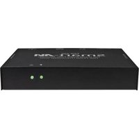
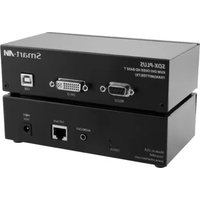
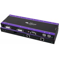
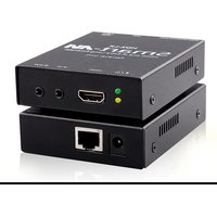
| Product Type | AV Extender |
| Model | SM-EYE2 |
| Brand | Smart-AVI |
| Connectivity | HDMI input and output; IR pass-through; RS-232 |
| Maximum Resolution | 1920x1080 @ 60Hz |
| Maximum Transmission Distance | Up to 60 meters over CAT5e/6 |
| Power Supply | 5V DC via USB or included power adapter |
| Dimensions (L x W x H) | 8.5 x 5.5 x 2.5 cm (approx.) |
| Weight | 120 g (approx.) |
| Enclosure Material | Metal housing |
| Operating Temperature | 0°C to 50°C |
| Compliance | HDCP 1.4 compliant |
| Included Accessories | Transmitter and receiver units, power adapters, IR cables, user manual |
| Installation | Plug and play, no drivers required |
| Maintenance | Wipe with dry cloth; avoid liquid cleaners |
| Safety | Use only supplied power adapter; keep away from moisture |
| Repairability | No user-serviceable parts; contact support for repairs |
Frequently Asked Questions - SM-EYE2 Smart-AVI
User questions about SM-EYE2 Smart-AVI
0 question about this device. Answer the ones you know or ask your own.
Ask a new question about this device
Download the instructions for your AV Extender in PDF format for free! Find your manual SM-EYE2 - Smart-AVI and take your electronic device back in hand. On this page are published all the documents necessary for the use of your device. SM-EYE2 by Smart-AVI.
USER MANUAL SM-EYE2 Smart-AVI
with Front Panel, RS-232, IR, and TCP/IP Control
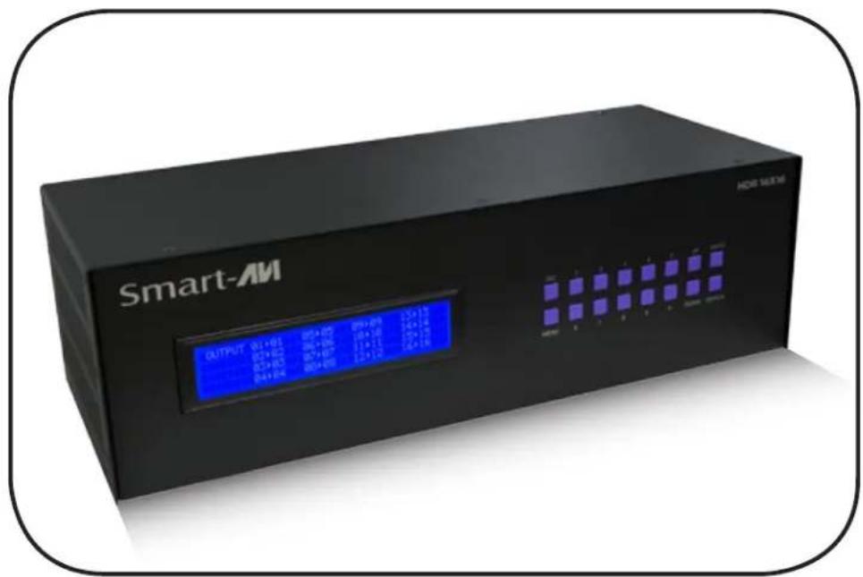
Display Content From Any 16 HDMI Sources On Any 16 Displays Independently Up To 40 Feet Away
What's in the Box?
| PART NO. QTY DESCRIPTION | ||
| HDR16X16 1 HDMI 1 | 6x16 Router. Includes :[HDR16X16 & PS5VDC4A] | |
| CCPWR06 1 6ft Power Cord | ||
HDR 16X16 Front

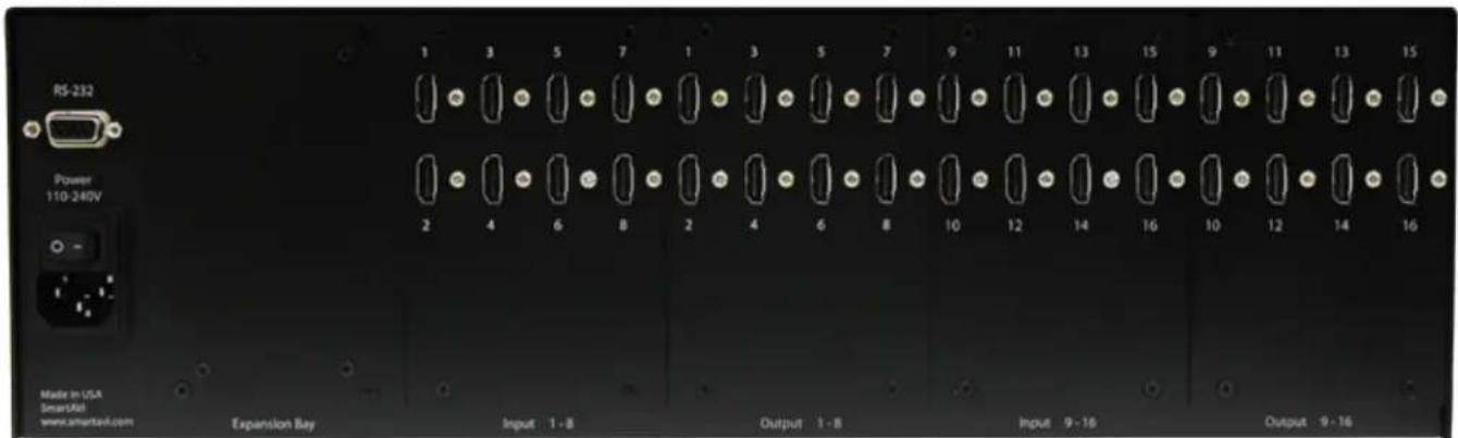
HDR 16X16 Rear
Introduction
The HDR16X16 conforms to the HDMI (High Definition Media Interface) standard and provides a connection to view any sixteen HDMI video sources on any combination of sixteen video displays. The matrix configuration provides maximum flexibility, allowing switching between any high-definition source and/or display. The SmartAVI HDMI Router 16X16 provides HDMI output up to 40 feet and at HDTV resolutions of 480p, 720p, 1080i and 1080p. The system works with HD-DVD players, TiVo systems, HT PCs, and satellite set-top boxes that connect to an HDMI display. And users can switch to any source locally or remotely via Front Panel, RS-232, IR, or TCP/IP connection. Our DVI router is controlled by Windows®-based software that is easy to understand and simple to use – a cornerstone of all SmartAVI products.
Features
• Switches 16 HDMI inputs with 16 HDMI outputs
- Sources can be routed independently to displays
• Switching controlled via the front panel, RS-232, IR, USB and TCP/IP
• Supports high definition video resolutions of 480p, 720p, 1080i and 1080p
• Supports 7.1 Digital Surround Sound Audio
• HDCP and HDMI 1.4 compliant
• Supports EDID for total control of compliant displays
• Delivers uncompressed digital video with zero signal loss
• Outputs HDMI up to 40 feet
- Rack-mountable
Technical Specifications
| VIDEO | |
| HDTV Resolutions 480p, 720p, 1080i, 1080p | |
| TV Resolution 480i | |
| Input Interface (16) HDMI Type A 19-pin Female TMDS | |
| Output Interface (16) HDMI Type A 19-pin Female TMDS | |
| Input Cable Length Up to 40 ft. | |
| Output Cable Length Up to 40 ft. | |
| OTHER | |
| Warranty Limited 1 Year Parts and Labor | |
| Control Panel, RS-232, IR, USB and TCP/IP | |
| Power Internal 100-240 VAC | |
| Dimensions 19"W x 5.25"H (2U) x 7"D | |
| Weight 10 lbs. | |
| HDR 16X16 Approvals FCC, CE, RoHS Compliant | |
| Power Supply Approvals | UL, CE, CSA, CEC, RoHS |
| ENVIRONMENTAL | |
| Operating Temperature | 0 to +40°C (+32° to 104°F) |
| Operating Humidity | 10% to 85% (Non-condensing) |
| Storage Temperature | -20° to +60° (+20° to +140°F) |
| Storage Humidity | 10% to 85% (Non-condensing) |
Application Diagram

flowchart
graph TD
    A["Rack Servers"] --> B["Computer"]
    B --> C["Gaming Console"]
    C --> D["Blueray Player"]
    D --> E["Video Camera"]
    E --> F["Signage Player"]
    F --> G["IR-EYE"]
    G --> H["SRC-2A"]
    H --> I["IR Control"]
    I --> J["RS-232, USB Control"]
    J --> K["TCP/IP Control"]
    K --> L["SMTCP"]
    L --> M["Internet"]
    style A fill:#f9f,stroke:#333
    style B fill:#ccf,stroke:#333
    style C fill:#cfc,stroke:#333
    style D fill:#fcc,stroke:#333
    style E fill:#cff,stroke:#333
    style F fill:#ffc,stroke:#333
    style G fill:#fcc,stroke:#333
    style H fill:#ffc,stroke:#333
    style I fill:#fcc,stroke:#333
    style J fill:#ffc,stroke:#333
    style K fill:#fcc,stroke:#333
    style L fill:#fcc,stroke:#333
    style M fill:#fcc,stroke:#333
Applications
• Corporate or Educational Presentations
• Financial (Remote Servers/User Control)
• Call Centers for Technical Support
• Industrial (Long-Range Workstation Isolation)
• Airport Installations (Air Traffic Control/Passenger Information)
• KVM Extension where Exceptional Quality of Signal is Crucial
• Medical (Remote Operation Away from Sensitive/Magnetic Equipment)
• Recording (for Large Studios where Editing/Mixing Stations are Compact and/or Require Complete Silence)
Installation
- Turn off all input devices and displays.
- Connect the HDMI extension cables to the input devices and to the "IN" ports on the HDR16X16.
- Connect the displays to the "OUT" ports on the HDR16X16.
- Connect the power cord and power-on the HDR16X16.
- Power on the input devices and the displays.
Switching Between Ports
There are four ways to switch between inputs on the HDR16X16: via the front panel buttons, IR remote control (optional), RS-232 connection, or TCP/IP (optional).
Front Panel Control
During normal operation, you will see a list of ports on the front panel display.
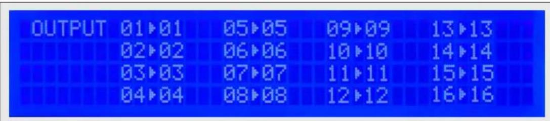
To assign an output to an input, press SWITCH. A blinking block cursor will appear. Use UP and DOWN to select the input that you would like to assign. Once the cursor is over the desired input port, press ENTER to enter editing mode. Press UP and DOWN to select the output port. Once you have selected an output, press ENTER to save the configuration. To escape from editing mode, press ESC.
Main Menu

To view the menu, press MENU. There are 6 menu options available:
RS-232 Acknowledge - Sets the HDR16X16 to send a confirmation that an RS-232 command has been received.
RS-232 Checksum - Sets the HDR16X16 to verify all RS-232 data for errors in transmission.
Send Update - Sets the HDR16X16 to send an RS-232 command back to the controller when the configuration is changed via the front panel or remote control (optional).
Memory Save - Sets the HDR16X16 to save the configuration when powered off.
Display Input Status - This displays the status of the inputs. If no input is present, the display will read NONE.

Restore Factory Settings - Sets the HDR16X16 to the default factory configuration.
Remote Control
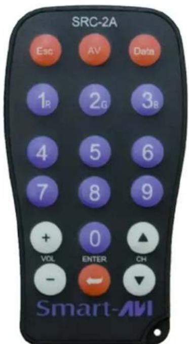
Begin by powering on the HDR16X16. Once powered on, press ESC on the remote control.
To assign an input to an output, simply press the 2 digit number of the input port, and then press ENTER, immediately followed by the 2 digit number of the output port, and then press ENTER.
For example: To assign input 1 to output 1, press 01, ENTER, 01, ENTER.
Note: the front panel display will not indicate the change until you have finished this process.
Optional Control
RS-232: Controlling the HDR 16X16 has never been simpler with SmartControl software. With SmartControl, you can assign a unique name to each port on the HDR 16X16, as well as each display, customizing projects to meet your needs. Although all the functions of the matrix are available locally on the front panel of the HDR 16X16, using SmartControl allows for customization of all the matrix functions.
USB: Computers that do not have an RS-232 port can connect to the HDR 16X16 via SmartAVI's USB to RS-232 converter. Utilize all the control of an RS-232 control interface with the simple and common USB interface. This solution is perfect for laptops and newer computers that only have a USB port.
IR: Many system professionals prefer the IR control interface because it offers greater flexibility to manage the HDR 16X16 at a distance. In some cases, the displays will not be visible from the matrix. In these situations it is necessary to control the matrix with Infrared control.
TCPIP: Remote control is essential to real-time management of the HDR 16X16. SmartAVI's SMTCP module is the perfect solution to effective remote management. Simply connect the SMTCP module to the HDR 16X16 and connect from anywhere on the internet. When you need to make a change, but can't be there in person, the SMTCP makes remote control a snap.
Controlling the HDR16X16 with the SMTCP module
The SMTCP-2 is an RS-232 control module that allows most SmartAVI switching matrixes to be controlled remotely via HTTP or TELNET. Manage the switching functions of your matrix with ease from anywhere in the world. With the SMTCP-2 you can save up to 10 preset input/output configurations for easy access. TELNET access provides transparent command control of your matrix, perfect for use with automated third-party control software.
Features
• Supports HTTP and TELNET control
• 10/100 Ethernet Interface
• Up to 10 user-definable configurations
- Password Protected
• Up to 5 Users can Control the Matrices
• IP Configuration via TCP/IP and RS-232
• Flexible control of several types of matrixes
Applications
• Server Collocation
- Digital Signage
- Airports
- Dealer Rooms
- Control Rooms
• Audio/Visual Presentations
• Hotels/Resorts
- KVM Switches
Technical Specifications
| Power External 100-240 V | AC/5VDC2A @10W |
| Dimensions 2.8125"W x 1"H x 3.375"D | |
| Weight 0.5 lbs | |
| Approvals UL, CE, ROHS | Compliant |
| Operating Temp. 32-131°F (0-55 °C) | |
| Storage Temp. -4-185 °F (-20-85 °C) | |
| Humidity Up to 95% | |
Controlling the HDR16X16 with the SMTCP module (continued)
Connecting to the SMTCP-2 for the first time
The first time you connect the SMTCP-2, you will need to perform the following steps to set the initial configuration. This includes establishing an HTTP connection and manually setting the IP address for the SMTCP-2.
- Power off all devices.
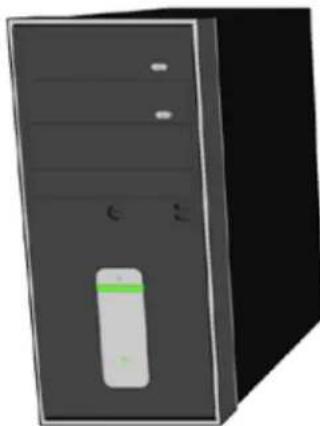
natural_image
3D rendering of a desktop computer tower with indicator lights and a green-labeled device (no text or symbols visible)COMPUTER
-
Use a female to male Straight-Through RS-232 (Serial) cable to connect the SMTCP-2 to the computer.
-
Use a CAT5 ethernet cable to connect the SMTCP-2 to a TCP/IP network via a network router or other network connection that has DHCP enabled. If your network does not support DHCP, please see page 22 of this manual for instructions.


natural_image
3D rendered model of a rectangular electronic device with no visible text or symbolsMATRIX SWITCH (NOT CONNECTED)
-
Power on the computer and run a terminal program such as Hyperterminal to open a serial connection to the SMTCP-2 using the standard 9600 baud, 8, N, 1 configuration.
-
Power on the SMTCP-2. When powered on, it will obtain an IP address automatically via DHCP from the network.
-
The IP information for the SMTCP-2 will be displayed on the terminal screen as follows:

addr:192.168.1.102
Mask:255.255.255.0
gtwy:192.168.1.1

NOTE: the above IP address is for demonstration purposes only. Actual results may be different.
- The IP address shown must be used to connect to the SMTCP via HTTP.
Controlling the HDR16X16 with the SMTCP module (continued)
-
Open a web browser and navigate to the IP address that is indicated. You will be prompted to enter a username and password.
-
The default login (case sensitive) is as follows:

User ID: Admin
Password: Pass
- Once connected to the SMTCP-2, you will see the following menu of options:

- Matrix
- Frame Address
- Device Config
- Network Setting
- User Administration
For the initial setup, click the Network Setting button and manually assign an IP address to the SMTCP-2. This will assure
that the SMTCP-2 will always have the same IP address. Be sure to choose an address that will not conflict with any other devices on the network, and that the address is not in the range of the DHCP server.


natural_image
3D rendering of a desktop computer tower with indicator lights and drive bays (no text or symbols visible)COMPUTER
- Once you have manually assigned an IP address to the SMTCP-2, you may disconnect the Straight-Through RS-232 (Serial) cable from the computer
- Connect the SMTCP-2 to the matrix switch with a Cross RS-232 (Serial) cable.

flowchart
graph LR
    A["IP ROUTER"] -->|CAT5| B["SMTCP-2"]
    B -->|RS-232 SERIAL| C["MATRIX SWITCH"]
    A -->|CAT5| D["Satellite"]
It is also recommended that you set a password for the SMTCP-2 at this point. To set the password (and/or username), click on the User Administration button, enter the password and click Submit. This sets the password for the HTTP interface only.
Controlling the HDR16X16 with the SMTCP module (continued)
Controlling the SMTCP-2 via HTTP
Once you have completed the Initial Setup for the SMTCP-2, you can now begin configuring it for your matrix. The following details the individual menu options in the web interface:
Matrix Menu

other
| Inputs: | Outputs: | 1 | 2 | 3 | 4 | 5 | 6 | 7 | 8 | |---|---|---|---|---|---|---|---|---|---| | 1 | ○ | ○ | ○ | ● | ● | ● | ○ | ○ | ○ | | this | ○ | ○ | ○ | ○ | ○ | ○ | ● | ● | ● | | is | ○ | ○ | ○ | ○ | ○ | ○ | ○ | ○ | ○ | | a | ○ | ○ | ○ | ○ | ○ | ○ | ○ | ○ | ○ | | test | ● | ○ | ○ | ○ | ○ | ○ | ○ | ○ | ○ | | 6 | ○ | ● | ○ | ○ | ○ | ○ | ○ | ○ | ○ | | 7 | ○ | ○ | ○ | ○ | ○ | ○ | ○ | ○ | ○ | | 8 | ○ | ○ | ○ | ○ | ○ | ○ | ○ | ○ | ○ | Matrix Preset This is a test 2 This is another 4 6 8 10 SAVE SAVE SAVE SAVE SAVE SAVEThe matrix menu allows you to set the crosspoints for the matrix. Crosspoints are used to route signals from the individual inputs to individual outputs. The output channels can only have one input, but each input can have several outputs.
Example shown in diagram:
Input 1 to Outputs 3,4,5
Input this to Outputs 6,7,8
Input test to Output 1
Input 6 to Output 2
The Matrix Preset option allows you to save and recall crosspoint configurations with the push of a button. To save a preset, simply configure your crosspoints and press the SAVE button next to the desired preset. To recall a preset, simply click on the button with its name. To edit the preset names, see the Device Config menu.
Frame Address Menu

The frame address menu allows you to set the frame address of the current matrix switch. Frame addresses allow commands to be sent to different matrixes in series. For more information on the specific commands available, please see the instructions for your matrix switch.
Controlling the HDR16X16 with the SMTCP module (continued)
Device Config Menu
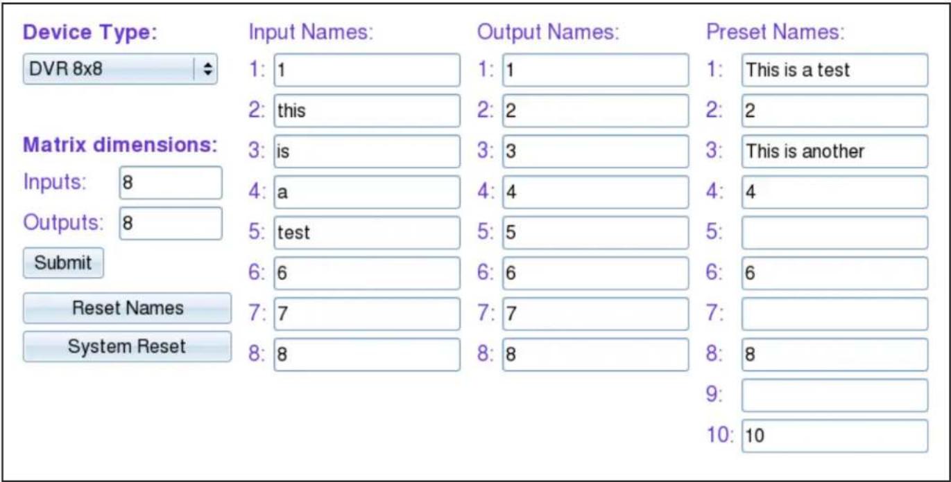
The device configuration menu allows you to select the type of matrix you are using, specify the dimensions of the matrix, and assign names to the inputs, outputs and presets, reset the names and reset the system to factory defaults.
To begin, set the type of device you are using from the drop-down menu labeled Device Type and specify the Matrix Dimensions. After specifying the Matrix Dimensions, press the Submit button to make the changes.
Once the type of matrix is entered, you can assign names to each of your inputs, outputs and presets. The preset names are used in the Matrix Menu for quick storage and retrieval of matrix configurations. Leaving a preset blank will exclude it from the Matrix Menu.
Network Setting Menu

The network setting menu allows you to assign a static IP address to the SMTCP-2. It is recommended that you statically assign an IP address to avoid any future conflict or connectivity issues with DHCP.
Controlling the HDR16X16 with the SMTCP module (continued)
User Administration Menu

The User Administration menu allows you to change the user name and password for the SMTCP-2. The default user name for the SMTCP-2 is Admin and the password is Pass. Once you modify the login information, press the Submit button to make the changes.
Controlling the SMTCP-2 via TELNET
Commands may be sent transparently to the matrix via a TELNET connection to the SMTCP-2. To use this function, use a telnet client such as Hyperterminal or PuTTY to connect to the IP address of the SMTCP-2. You will be prompted for a username and password - this will be the same as the login information via HTTP. Once logged in, the SMTCP-2 is ready to accept the standard RS-232 commands. For a list of the available commands, please see the user manual for the matrix you are using. Although the commands are not echoed to the client display, the commands are being issued to the matrix. Should you need commands to be echoed, please see the instructions for your TELNET client.
Upgrading the SMTCP-2
To upgrade the SMTCP-2 with the latest ☐rmware, contact your sales representative to obtain the ☐rmware upgrade ☐le or visit the SMTCP-2 product page at www.smartavi.com. The version information is listed on the Main Menu. Once you have the ☐le, use an FTP client, preferably TFTP, to navigate to the IP address of the SMTCP-2. To upload the ☐le to the SMTCP-2, navigate to the /var/ directory, and upload the ☐le ☐rmware.img - IMPORTANT: the file MUST BE NAMED ☐rmware.img for the upgrade to work properly. Again, the full path MUST BE /var/☐rmware.img. Once the ☐le has been copied, restart (power o and power on) the SMTCP-2. Once restarted the ☐rmware update will be installed. To verify the upgrade, see the version information listed on the Main Menu.


Controlling the HDR16X16 with the SMTCP module (continued)
Connecting to the SMTCP-2 for the first time WITHOUT DHCP
The first time you connect the SMTCP-2, you will need to perform the following steps to set the initial configuration. This includes establishing an HTTP connection and manually setting the IP address for the SMTCP-2.

-
Power on the computer and run a terminal program such as Hyperterminal to open a serial connection to the SMTCP-2 using the standard 9600 baud, 8, N, 1, None Flow Control configuration.
-
While powering on the SMTCP-2, press and hold Shift-1 (exclamation) until a command prompt appears.
-
Press enter to show the network configuration help screen as follows:
Command:
E……
° Network Configuration help °
E……
Enter a command followed by optional parameters
Commands are SET DHCP INFO RESET and QUIT/SAVE
SET command allows you to change the network configuration:
SI xxx.xxx.xxx.xxx = Set IP Address
(if IP address is not entered then DHCP is ENABLED)
SM xxx.xxx.xxx.xxx = Set IP Mask
SG xxx.xxx.xxx.xxx = Set Gateway Address
RN = Reset Network Params:
IPADDR = 192.168.0.2
IPMASK = 255.255.255.0
GATEWAY = 192.168.0.1
DHCP ON = Enable DHCP
DHCP OFF = Disable DHCP
INFO = Display network configuration
RESET = Factory reset
QUIT = Saves configuration and quits
SAVE = Same as QUITNOTE: the above IP address may be different.
- Follow the instructions to manually assign an IP address to the SMTCP-2.
- See page 19 for instructions on how to connect to the SMTCP-2 via HTTP.
RS-232 Specifications
How to properly create an RS-232 connection between a PC and most SmartAVI RS-232 compliant devices
Establish a connection to your RS-232 compliant device:
- Connect a straight through male to female RS-232 cable (shown on right) to the RS-232 connector on the PC.
- Connect the other end of the cable to the RS-232 compliant device.
- Power on the device.

natural_image
Coiled beige cable with two VGA connectors and a blue D-sub connector (no text or symbols visible)Male to Female Straight Cable (not provided)

Hyperterminal Settings
Setting up the Terminal application:
- Open Hyperterminal on the PC. (or use the terminal client of your choice)
- Use the default settings to create a connection to the device (see settings on left). Settings MUST match those shown on the lower right.
- Be sure that Flow Control is None.
- The output of the device will be the same as the PC.
RS-232 Specifications (continued)
How to properly test an RS-232 connection between a PC and most SmartAVI RS-232 compliant devices
After you have established a connection to your device use the following commands:
1) To set a video crosspoint:
e.g. to set video input 3 to output 12 on a router with frame address "0" send the command: //F00M12I03<0x42>
2) To set RS-232 crosspoint:
3) To disconnect RS-232 crosspoint:
4) To set new frame address:
$$ / / \mathbf {F} \mathbf {x x M y y I z z} < \mathbf {C H K} > < \mathbf {C R} > $$
$$ / / \mathbf {F} \mathbf {x x} \mathbf {R} \mathbf {y y} \mathbf {I} \mathbf {z z} < \mathbf {C H K} > < \mathbf {C R} > $$
$$ / / \mathbf {F} \mathbf {x x D} \mathbf {y y I} \mathbf {z z} < \mathbf {C H K} > < \mathbf {C R} > $$
$$ / / \mathbf {F} _ {\text {xx}} \mathbf {F} _ {\text {nn}} < \mathbf {C} \mathbf {H} \mathbf {K} > < \mathbf {C} \mathbf {R} > $$
IMPORTANT
CALCULATING THE
RS-232 Specifications (continued)
How to properly test an RS-232 connection between a PC and most SmartAVI RS-232 compliant devices
RS-232 Commands continued:
5) To query crosspoints from PC:
//FxxU<CHK><CR>
- If all outputs are connected to input 1 then a 4x4 Matrix will respond with <0x80><0x80><0x80><0x80>
- The router will send back one byte for each output and the string ends with a
. The first byte sent is Output #1. In the example above, since there are 5 bytes total, we know that there are 4 outputs. - To calculate the input number, the router sends the input number with the 7^th bit set.
○ 0x80 = "1000 0000" → input 0
○ 0x81 = "1000 0001" → input 1
○ ...
○ 0x8F “1000 1111” → input 15
Comms Port Settings:
| Baud Rate | 9600 |
| Start Bits | 1 |
| Data Bits | 8 |
| Parity | None |
| Stop Bits | 1 |
Notes:
- When successful, commands #1-4 will acknowledge by sending the checksum with nibbles swapped &
o e.g. checksum of 0x24 acknowledges with <0x42>
RS-232 Specifications (continued)
How to properly test an RS-232 connection between a PC and most SmartAVI RS-232 compliant devices
The following are example commands for the first 8 inputs and 8 outputs. The hexadecimal values of the commands are also listed.
Operation Command
| input_1_output_1 | //F00M01101 | 2F 2F 46 30 30 4D 30 31 49 30 31 42 0D |
| input_2_output_1 | //F00M01102 | 2F 2F 46 30 30 4D 30 31 49 30 32 41 0D |
| input_3_output_1 | //F00M01103 | 2F 2F 46 30 30 4D 30 31 49 30 33 40 0D |
| input_4_output_1 | //F00M01104 | 2F 2F 46 30 30 4D 30 31 49 30 34 47 0D |
| input_5_output_1 | //F00M01105 | 2F 2F 46 30 30 4D 30 31 49 30 35 46 0D |
| input_6_output_1 | //F00M01106 | 2F 2F 46 30 30 4D 30 31 49 30 36 45 0D |
| input_7_output_1 | //F00M01107 | 2F 2F 46 30 30 4D 30 31 49 30 37 44 0D |
| input_8_output_1 | //F00M01108 | 2F 2F 46 30 30 4D 30 31 49 30 38 4B 0D |
| input_1_output_2 | //F00M02101 | 2F 2F 46 30 30 4D 30 32 49 30 31 41 0D |
| input_2_output_2 | //F00M02102 | 2F 2F 46 30 30 4D 30 32 49 30 32 42 0D |
| input_3_output_2 | //F00M02103 | 2F 2F 46 30 30 4D 30 32 49 30 33 43 0D |
| input_4_output_2 | //F00M02104 | 2F 2F 46 30 30 4D 30 32 49 30 34 44 0D |
| input_5_output_2 | //F00M02105 | 2F 2F 46 30 30 4D 30 32 49 30 35 45 0D |
| input_6_output_2 | //F00M02106 | 2F 2F 46 30 30 4D 30 32 49 30 36 46 0D |
| input_7_output_2 | //F00M02107 | 2F 2F 46 30 30 4D 30 32 49 30 37 47 0D |
| input_8_output_2 | //F00M02108 | 2F 2F 46 30 30 4D 30 32 49 30 38 48 0D |
| input_1_output_3 | //F00M03101 | 2F 2F 46 30 30 4D 30 33 49 30 31 40 0D |
| input_2_output_3 | //F00M03102 | 2F 2F 46 30 30 4D 30 33 49 30 32 43 0D |
| input_3_output_3 | //F00M03103 | 2F 2F 46 30 30 4D 30 33 49 30 33 42 0D |
| input_4_output_3 | //F00M03104 | 2F 2F 46 30 30 4D 30 33 49 30 34 45 0D |
| input_5_output_3 | //F00M03105 | 2F 2F 46 30 30 4D 30 33 49 30 35 44 0D |
| input_6_output_3 | //F00M03106 | 2F 2F 46 30 30 4D 30 33 49 30 36 47 0D |
| input_7_output_3 | //F00M03107 | 2F 2F 46 30 30 4D 30 33 49 30 37 46 0D |
| input_8_output_3 | //F00M03108 | 2F 2F 46 30 30 4D 30 33 49 30 38 49 0D |
| input_1_output_4 | //F00M04101 | 2F 2F 46 30 30 4D 30 34 49 30 31 47 0D |
| input_2_output_4 | //F00M04102 | 2F 2F 46 30 30 4D 30 34 49 30 32 44 0D |
| input_3_output_4 | //F00M04103 | 2F 2F 46 30 30 4D 30 34 49 30 33 45 0D |
| input_4_output_4 | //F00M04104 | 2F 2F 46 30 30 4D 30 34 49 30 34 42 0D |
| input_5_output_4 | //F00M04105 | 2F 2F 46 30 30 4D 30 34 49 30 35 43 0D |
| input_6_output_4 | //F00M04106 | 2F 2F 46 30 30 4D 30 34 49 30 36 40 0D |
| input_7_output_4 | //F00M04107 | 2F 2F 46 30 30 4D 30 34 49 30 37 41 0D |
| input_8_output_4 | //F00M04108 | 2F 2F 46 30 30 4D 30 34 49 30 38 4E 0D |
| input_1_output_5 | //F00M05101 | 2F 2F 46 30 30 4D 30 35 49 30 31 46 0D |
| input_2_output_5 | //F00M05102 | 2F 2F 46 30 30 4D 30 35 49 30 32 45 0D |
| input_3_output_5 | //F00M05103 | 2F 2F 46 30 30 4D 30 35 49 30 33 44 0D |
| input_4_output_5 | //F00M05104 | 2F 2F 46 30 30 4D 30 35 49 30 34 43 0D |
| input_5_output_5 | //F00M05105 | 2F 2F 46 30 30 4D 30 35 49 30 35 42 0D |
| input_6_output_5 | //F00M05106 | 2F 2F 46 30 30 4D 30 35 49 30 36 41 0D |
| input_7_output_5 | //F00M05107 | 2F 2F 46 30 30 4D 30 35 49 30 37 40 0D |
| input_8_output_5 | //F00M05108 | 2F 2F 46 30 30 4D 30 35 49 30 38 4F 0D |
Hexidecimal Value
RS-232 Specifications (continued)
How to properly test an RS-232 connection between a PC and most SmartAVI RS-232 compliant devices
| input_1_output_6 | //F00M06I01 | <CHK> | <CR> | 2F 2F 46 30 30 4D 30 36 49 30 31 45 0D |
| input_2_output_6 | //F00M06I02 | <CHK> | <CR> | 2F 2F 46 30 30 4D 30 36 49 30 32 46 0D |
| input_3_output_6 | //F00M06I03 | <CHK> | <CR> | 2F 2F 46 30 30 4D 30 36 49 30 33 47 0D |
| input_4_output_6 | //F00M06I04 | <CHK> | <CR> | 2F 2F 46 30 30 4D 30 36 49 30 34 40 0D |
| input_5_output_6 | //F00M06I05 | <CHK> | <CR> | 2F 2F 46 30 30 4D 30 36 49 30 35 41 0D |
| input_6_output_6 | //F00M06I06 | <CHK> | <CR> | 2F 2F 46 30 30 4D 30 36 49 30 36 42 0D |
| input_7_output_6 | //F00M06I07 | <CHK> | <CR> | 2F 2F 46 30 30 4D 30 36 49 30 37 43 0D |
| input_8_output_6 | //F00M06I08 | <CHK> | <CR> | 2F 2F 46 30 30 4D 30 36 49 30 38 4F 0D |
| input_1_output_7 | //F00M07I01 | <CHK> | <CR> | 2F 2F 46 30 30 4D 30 37 49 30 31 44 0D |
| input_2_output_7 | //F00M07I02 | <CHK> | <CR> | 2F 2F 46 30 30 4D 30 37 49 30 32 47 0D |
| input_3_output_7 | //F00M07I03 | <CHK> | <CR> | 2F 2F 46 30 30 4D 30 37 49 30 33 46 0D |
| input_4_output_7 | //F00M07I04 | <CHK> | <CR> | 2F 2F 46 30 30 4D 30 37 49 30 34 41 0D |
| input_5_output_7 | //F00M07I05 | <CHK> | <CR> | 2F 2F 46 30 30 4D 30 37 49 30 35 40 0D |
| input_6_output_7 | //F00M07I06 | <CHK> | <CR> | 2F 2F 46 30 30 4D 30 37 49 30 36 43 0D |
| input_7_output_7 | //F00M07I07 | <CHK> | <CR> | 2F 2F 46 30 30 4D 30 37 49 30 37 42 0D |
| input_8_output_7 | //F00M07I08 | <CHK> | <CR> | 2F 2F 46 30 30 4D 30 37 49 30 38 40 0D |
| input_1_output_8 | //F00M08I01 | <CHK> | <CR> | 2F 2F 46 30 30 4D 30 38 49 30 31 4B 0D |
| input_2_output_8 | //F00M08I02 | <CHK> | <CR> | 2F 2F 46 30 30 4D 30 38 49 30 32 48 0D |
| input_3_output_8 | //F00M08I03 | <CHK> | <CR> | 2F 2F 46 30 30 4D 30 38 49 30 33 49 0D |
| input_4_output_8 | //F00M08I04 | <CHK> | <CR> | 2F 2F 46 30 30 4D 30 38 49 30 34 4E 0D |
| input_5_output_8 | //F00M08I05 | <CHK> | <CR> | 2F 2F 46 30 30 4D 30 38 49 30 35 4F 0D |
| input_6_output_8 | //F00M08I06 | <CHK> | <CR> | 2F 2F 46 30 30 4D 30 38 49 30 36 4C 0D |
| input_7_output_8 | //F00M08I07 | <CHK> | <CR> | 2F 2F 46 30 30 4D 30 38 49 30 37 4D 0D |
| input_8_output_8 | //F00M08I08 | <CHK> | <CR> | 2F 2F 46 30 30 4D 30 38 49 30 38 42 0D |
| Query Current Matrix //F00U | <CR> | 2F 2F 46 30 30 55 13 0D | ||
RS-232 SPECIFICATIONS
| CONNECTOR | PIN | NAME | DESCRIPTION |
DB9 MALE - RECEIVE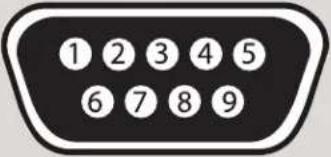 | 2 | RxD | Receive Data on DB9 Male |
| 3 | TxD | Transmit Data on DB9 Male | |
| 5 | SGND | Ground | |
DB9 FEMALE - TRANSMIT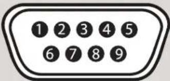 | 2 | TxD | Transmit Data on DB9 Female |
| 3 | RxD | Receive Data on DB9 Female | |
| 5 | SGND | Ground |
Limited Warranty Statement
A. Extent of limited warranty
-
SmartAVI Technologies, Inc. warrants to the end-user customers that the SmartAVI product specified above will be free from defects in materials and workmanship for the duration of 1 year, which duration begins on the date of purchase by the customer. Customer is responsible for maintaining proof of date of purchase.
-
SmartAVI limited warranty covers only those defects which arise as a result of normal use of the product, and do not apply to any:
a. Improper or inadequate maintenance or modifications
b. Operations outside product specifications
c. Mechanical abuse and exposure to severe conditions
-
If SmartAVI receives, during applicable warranty period, a notice of defect, SmartAVI will at its discretion replace or repair defective product. If SmartAVI is unable to replace or repair defective product covered by the SmartAVI warranty within reasonable period of time, SmartAVI shall refund the cost of the product.
-
SmartAVI shall have no obligation to repair, replace or refund unit until customer returns defective product to SmartAVI.
-
Any replacement product could be new or like new, provided that it has functionality at least equal to that of the product being replaced.
-
SmartAVI limited warranty is valid in any country where the covered product is distributed by SmartAVI.
B. Limitations of warranty
TO THE EXTENT ALLOWED BY LOCAL LAW, NEITHER SMARTAVI NOR ITS THIRD PARTY SUPPLIERS MAKE ANY OTHER WARRANTY OR CONDITION OF ANY KIND WHETHER EXPRESSED OR IMPLIED, WITH RESPECT TO THE SMARTAVI PRODUCT, AND SPECIFICALLY DISCLAIM IMPLIED WARRANTIES OR CONDITIONS OF MERCHANTABILITY, SATISFACTORY QUALITY, AND FITNESS FOR A PARTICULAR PURPOSE
C. Limitations of liability
To the extent allowed by local law the remedies provided in this warranty statement are the customers sole and exclusive remedies
TO THE EXTENT ALLOWED BY LOCAL LAW, EXCEPT FOR THE OBLIGATIONS SPECIFICALLY SET FORTH IN THIS WARRANTY STATEMENT, IN NO EVENT WILL SMARTAVI OR ITS THIRD PARTY SUPPLIERS BE LIABLE FOR DIRECT, INDIRECT, SPECIAL, INCIDENTAL, OR CONSEQUENTIAL DAMAGES WHETHER BASED ON CONTRACT, TORT OR ANY OTHER LEGAL THEORY AND WHETHER ADVISED OF THE POSSIBILITY OF SUCH DAMAGES.
D. Local law
To the extent that this warranty statement is inconsistent with local law, this warranty statement shall be considered modified to be consistent with such law.
NOTES
© Copyright 2012 SmartAVI, All Rights Reserved
NOTICE
The information contained in this document is subject to change without notice. SmartAVI makes no warranty of any kind with regard to this material, including but not limited to, implied warranties of merchantability and fitness for any particular purpose.
SmartAVI will not be liable for errors contained herein or for incidental or consequential damages in connection with the furnishing, performance or use of this material.
No part of this document may be photocopied, reproduced or translated into another language without prior written consent from SmartAVI.
For more information, visit www.smartavi.com.
Smart-AM
SMART AUDIO VIDEO INNOVATION
SmartAVI, Inc. / Twitter: smartavi
11651 Vanowen St. North Hollywood, CA 91605
Tel: (818) 503-6200 Fax: (818) 503-6208
http://www.SmartAVI.com
- What's in the Box?
- Introduction
- Features
- Application Diagram
- Applications
- Installation
- Switching Between Ports
- Front Panel Control
- Main Menu
- Remote Control
- Optional Control
- Controlling the HDR16X16 with the SMTCP module
- Controlling the HDR16X16 with the SMTCP module (continued)
- Connecting to the SMTCP-2 for the first time
- Controlling the SMTCP-2 via HTTP
- Device Config Menu
- Network Setting Menu
- Controlling the SMTCP-2 via TELNET
- Upgrading the SMTCP-2
- Connecting to the SMTCP-2 for the first time WITHOUT DHCP
- RS-232 Specifications
- Establish a connection to your RS-232 compliant device:
- Setting up the Terminal application:
- RS-232 Specifications (continued)
- After you have established a connection to your device use the following commands:
- IMPORTANT
- CALCULATING THE
- RS-232 Commands continued:
- 5) To query crosspoints from PC:
- Notes:
- The following are example commands for the first 8 inputs and 8 outputs. The hexadecimal values of the commands are also listed.
- Limited Warranty Statement
- Extent of limited warranty
- Limitations of warranty
- Limitations of liability
- Local law
- NOTICE
Brand : Smart-AVI
Model : SM-EYE2
Category : AV Extender