
ARMBARTRIO2 - Flat Screen Mount StarTech.com - Free user manual and instructions
Find the device manual for free ARMBARTRIO2 StarTech.com in PDF.


| Product Type | Dual Monitor Desk Mount Arm |
| Model | ARMBARTRIO2 |
| Brand | StarTech.com |
| Maximum Screen Size | Up to 32 inches per monitor |
| VESA Compatibility | 75x75mm and 100x100mm |
| Weight Capacity per Arm | 17.6 lbs (8 kg) |
| Total Weight Capacity | 35.2 lbs (16 kg) |
| Material | Aluminum and Steel |
| Color | Black |
| Desk Clamp Thickness | 0.4 to 3.3 inches (10 to 85 mm) |
| Grommet Mount Hole Size | 0.4 to 2.4 inches (10 to 60 mm) |
| Arm Reach | 19.7 inches (500 mm) per arm |
| Tilt Range | -90° to +90° |
| Swivel Range | 360° |
| Rotation Range | 360° |
| Height Adjustment | Gas spring, 13.4 inches (340 mm) |
| Dimensions (Length x Width x Height) | 34.6 x 6.3 x 22.8 inches (880 x 160 x 580 mm) |
| Weight | 12.3 lbs (5.6 kg) |
| Power Supply | None (mechanical) |
| Cable Management | Integrated cable clips |
| Mounting Options | Desk clamp or grommet mount |
| Cleaning Instructions | Wipe with a dry, lint-free cloth. Do not use solvents. |
| Safety Notices | Ensure weight capacity not exceeded. Tighten all bolts securely. |
| Spare Parts Availability | Visit StarTech.com for replacement parts |
| Repairability | Repairable by qualified technician; contact support for service. |
Frequently Asked Questions - ARMBARTRIO2 StarTech.com
User questions about ARMBARTRIO2 StarTech.com
0 question about this device. Answer the ones you know or ask your own.
Ask a new question about this device
Download the instructions for your Flat Screen Mount in PDF format for free! Find your manual ARMBARTRIO2 - StarTech.com and take your electronic device back in hand. On this page are published all the documents necessary for the use of your device. ARMBARTRIO2 by StarTech.com.
USER MANUAL ARMBARTRIO2 StarTech.com
Triple-Monitor Stand
ARMBARTRIO2
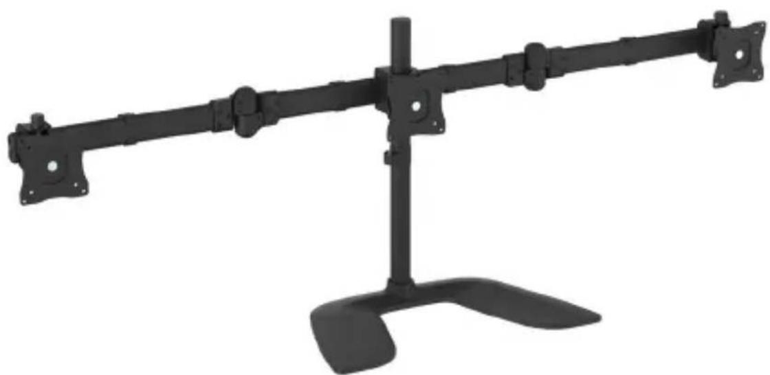
natural_image
Black industrial machine with three blades mounted on a stand (no text or symbols visible)*actual product may vary from photos
For the latest information, technical specifications, and support for this product, please visit www.StarTech.com/ARMBARTRIO2.
Use of Trademarks, Registered Trademarks, and other Protected Names and Symbols
PHILLIPS ^® is a registered trademark of Phillips Screw Company in the United States or other countries.
This manual may make reference to trademarks, registered trademarks, and other protected names and/or symbols of third-party companies not related in any way to StarTech.com. Where they occur these references are for illustrative purposes only and do not represent an endorsement of a product or service by StarTech.com, or an endorsement of the product(s) to which this manual applies by the third-party company in question. Regardless of any direct acknowledgement elsewhere in the body of this document, StarTech.com hereby acknowledges that all trademarks, registered trademarks, service marks, and other protected names and/or symbols contained in this manual and related documents are the property of their respective holders.
Warning statements
Make sure that you assemble this product according to the instructions.
Read the entire manual and make sure that you understand the instructions before you start to assemble and use this product.
Do not exceed the weight capacity of this product. Overloading this product might result in injury or property damage. This product can support the following weight: Up to 8 kg (17.6 lb.) per monitor.
When you assemble this product, do not over-tighten the screws. If you encounter resistance while you are tightening the screws, stop tightening.
Do not allow any part of your component cables to get caught between moveable parts, as it could result in equipment damage.
Warnhinweise
Product diagram ......1
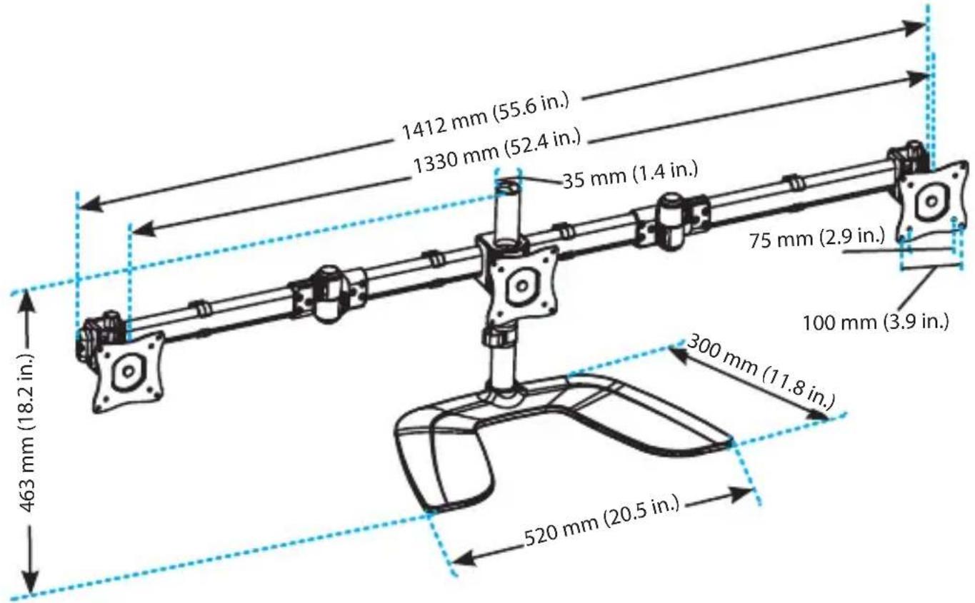
Product dimensions....1
Technical specifications ....2
Package contents....3
Requirements ....5
Assembling the triple-monitor stand ....6
Assemble the base....6
Attach a monitor to the crossbar....7
Attach the VESA monitor mounts 8
Attach the monitors to the monitor arms....9
Attach the crossbar and monitor arms....11
Attach the cable-management clips....14
Adjust the position of the monitors....15
Tipping hazard warning....15
Technical support....19
Warranty information....19
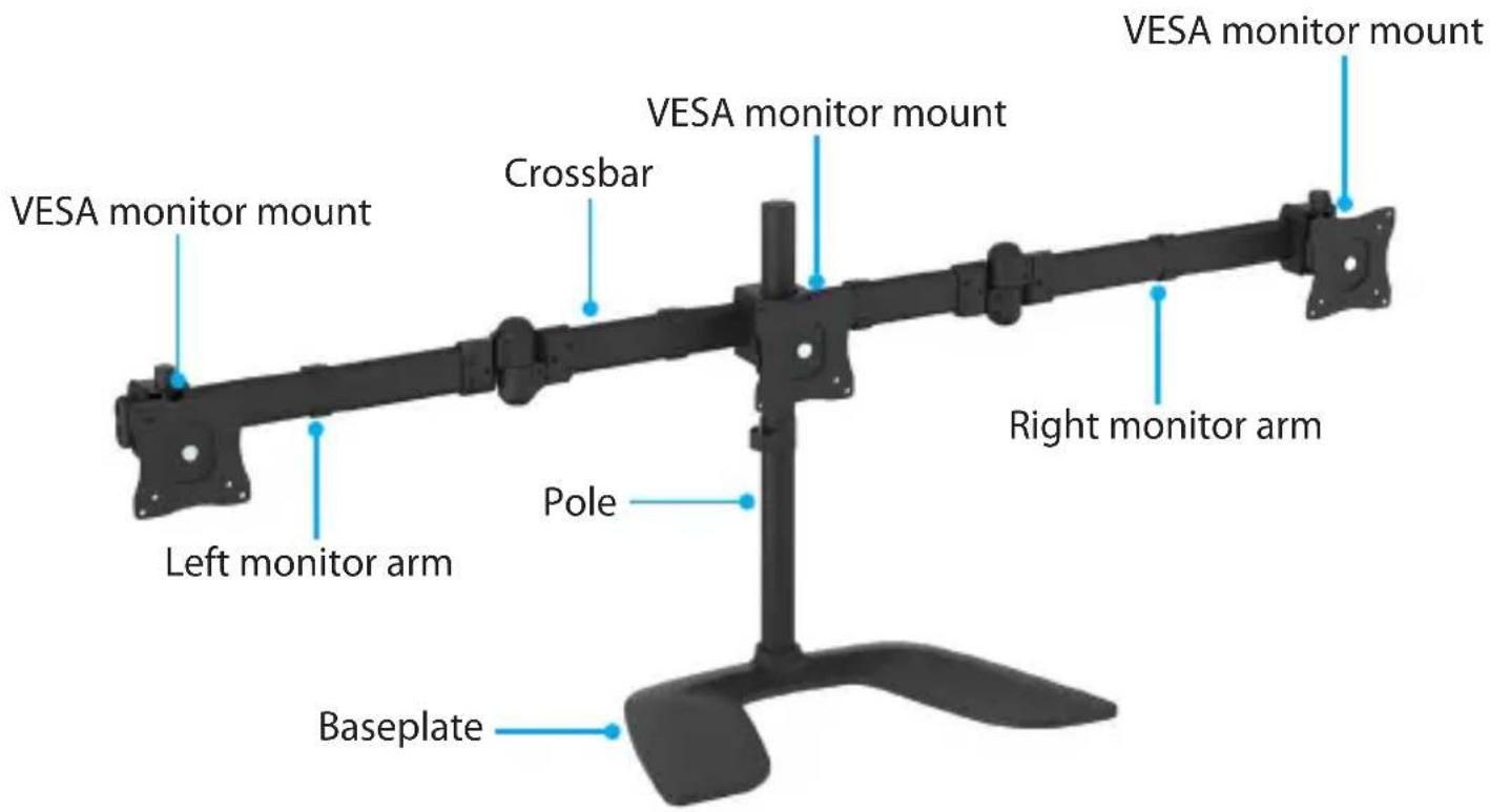
Product diagram
Product dimensions
Technical specifications
Type of measurement Measurement
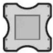
VESA
75×75
100×100

RATED LOAD
17.6 lb. (8 kg) per monitor
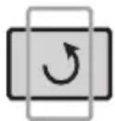
ROTATION
360^

TILT
-30^ to +30^
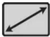
SCREEN
Up to 686 mm (27 in.)
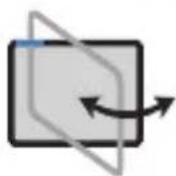
SWIVEL
-30^ to +30^
Package contents
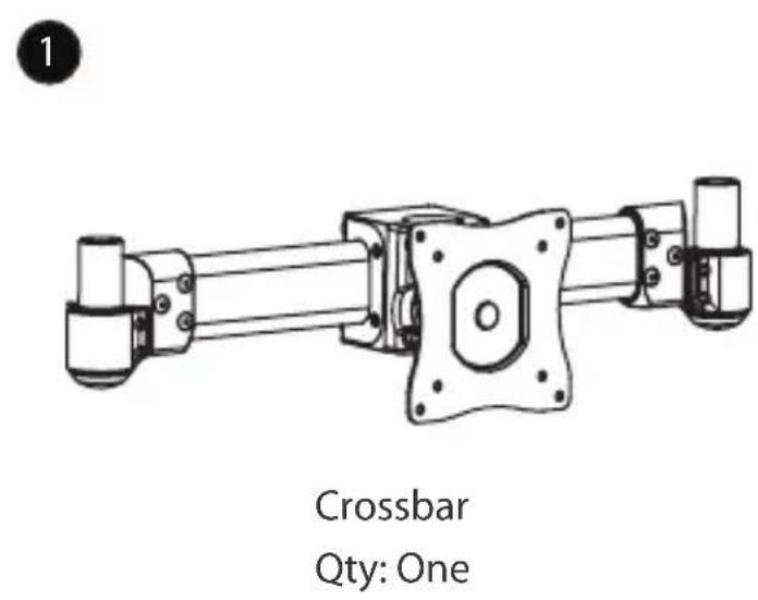
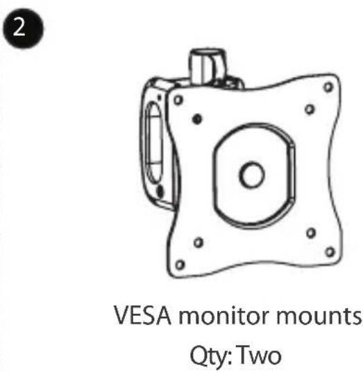
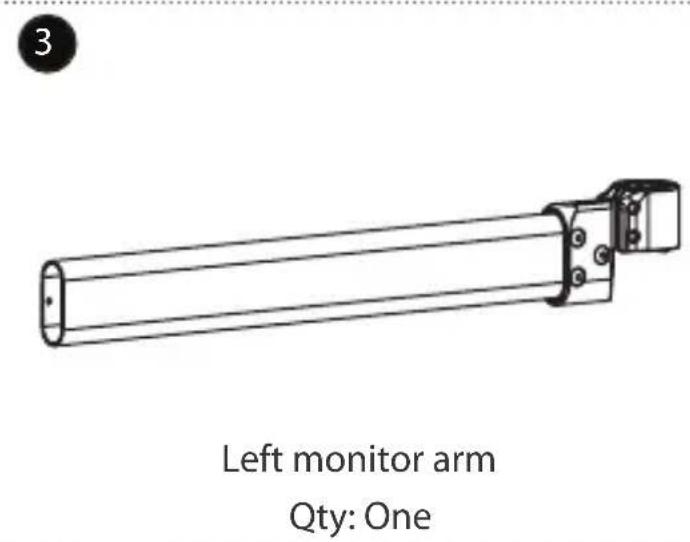
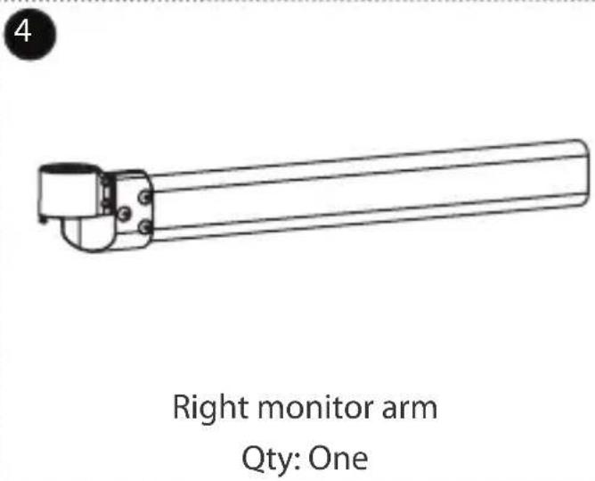
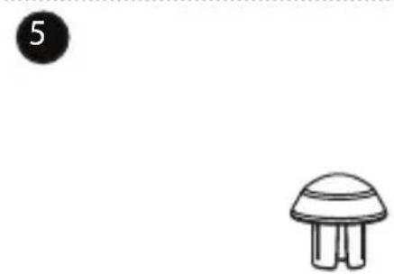
natural_image
Simple line drawing of a mushroom with a circular label (5) and a small figure below it (no text or symbols)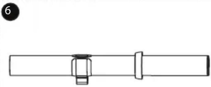
natural_image
Pure mechanical assembly diagram showing a shaft and bolted joint (no text or symbols)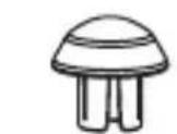
Arm caps Qty: Two
Pole Qty: One
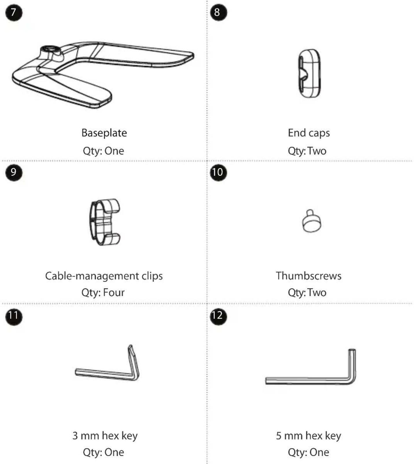
other
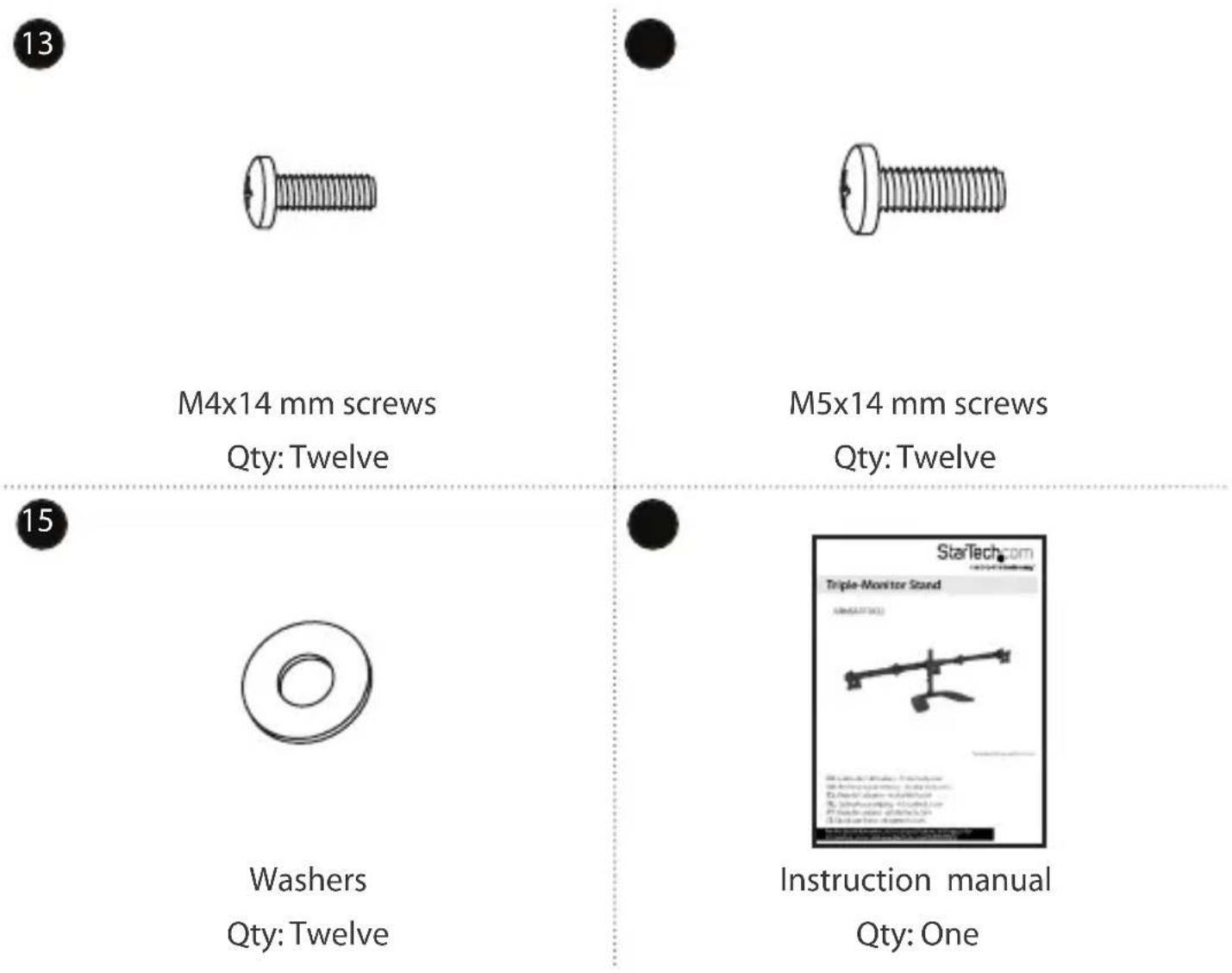
13 M4x14 mm screws Qty: Twelve 15 M5x14 mm screws Qty: Twelve 15 Washers Qty: Twelve Instruction manual Qty: OneRequirements
- Three monitors that are compatible with one of the VESA mounting hole patterns that ARMBARTRIO2 supports
• A Phillips type screwdriver
Requirements are subject to change. For the latest requirements, please visit www.StarTech.com.ARMBARTRIO2.
Assembling the triple-monitor stand
Assemble the base
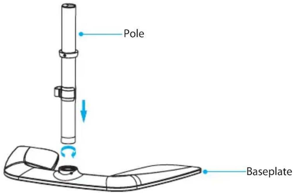
1. Screw the pole into the baseplate. (figure 1)
figure 1
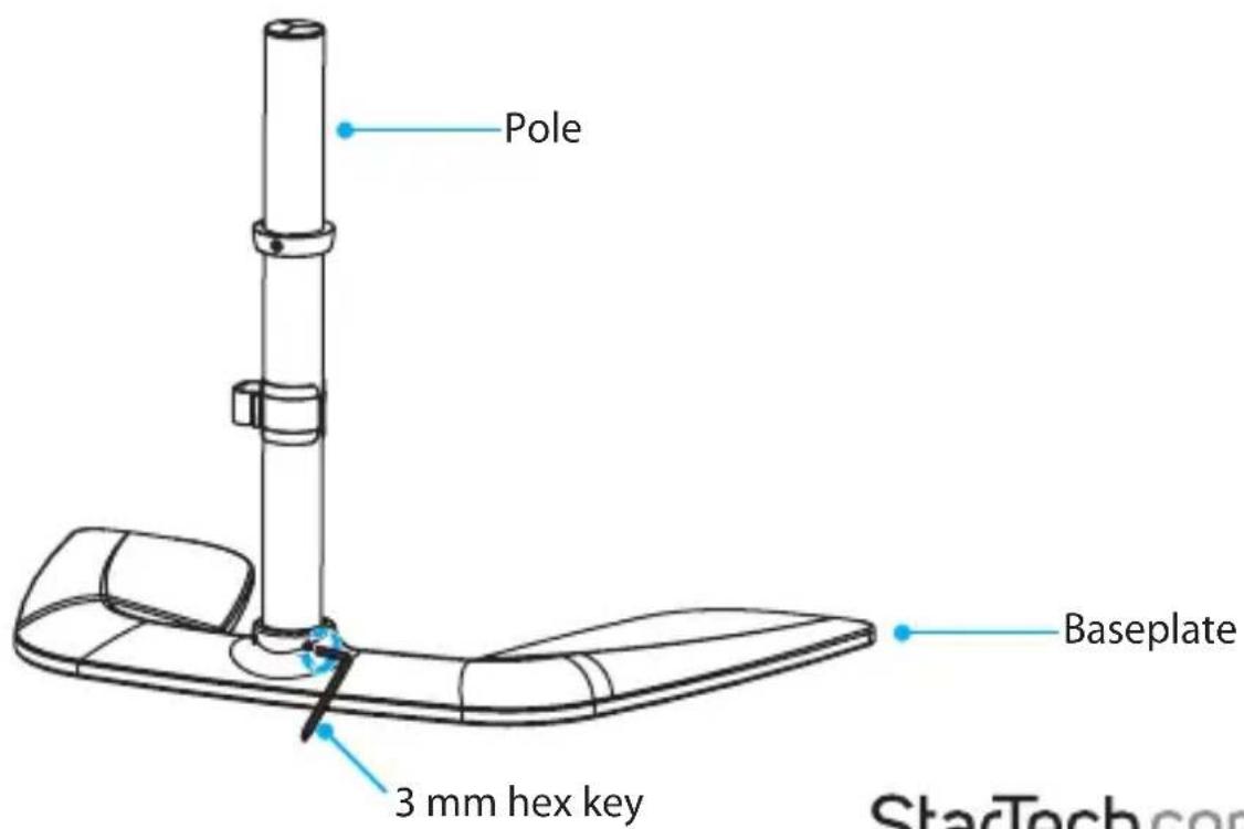
2. Use the 3 mm hex key to tighten the set screws to secure the pole to the baseplate. (figure 2)
figure 2
Attach a monitor to the crossbar
Warning! Make sure that the weight of the monitor that you attach to the crossbar does not exceed the weight capacity of this product. If you exceed the weight capacity, you might experience personal injury or damage to the product.
This product can support up to 17.6 lb. (8 kg) per monitor.
- To accommodate different monitor designs, the ARMBARTRIO2 comes with two sets of screws that are different lengths and diameters. To select the appropriate screws for the type of monitors that you're using, determine the depth and diameter of the mounting holes on the monitors.
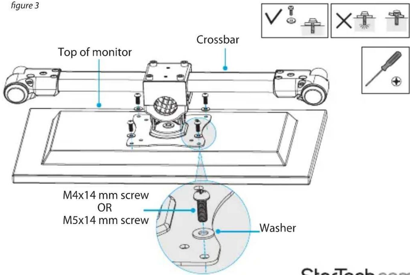
- Arrange the crossbar so that the holes on the VESA monitor mount line up with the mounting holes on the back of one of your monitors.
- Position four of the washers over the holes on the VESA monitor mount.
- Insert four of the M4x14 mm screws or the M5x14 mm screws through the washers, the VESA monitor mount, and into the monitor. (figure 3)
- Use a Phillips type screwdriver to tighten the screws.
Warning! Do not over-tighten the screws. If you encounter resistance while you're tightening the screws, stop tightening. Failure to do so could result in damage to the monitor.
Attach the VESA monitor mounts
Warning! Make sure that the weight of the monitors that you are using does not exceed the weight capacity of this product. If you exceed the weight capacity, you might experience personal injury or damage to the product.
This product can support up to 17.6 lb. (8 kg) per monitor.
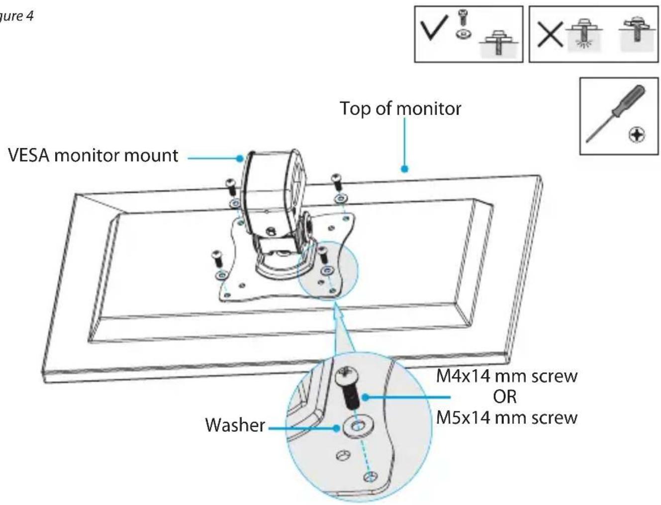
- Position one of the VESA monitor mounts over the mounting holes on the back of one of the monitors.
Note: Make sure that you position the VESA monitor mount so that the adjustment screw on the mount is facing towards the top of the monitor. - Position four of the washers over the holes on the VESA monitor mount.
- Insert four of the M4x14 mm screws or the M5x14 mm screws through the washers, the VESA monitor mount, and into the monitor. (figure 4)
- Use a Phillips type screwdriver to tighten the screws.
- Repeat steps 1 to 4 to attach the second VESA monitor mount to the third monitor.
figure 4
Attach the monitors to the monitor arms
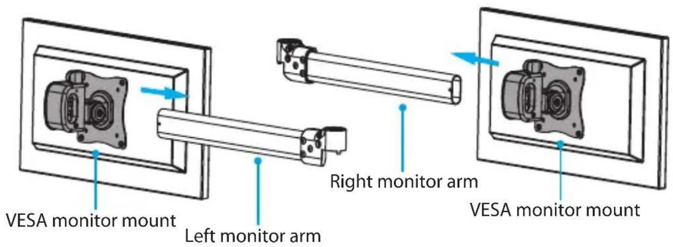
- Slide the left monitor arm through the VESA monitor mount attached to one of the monitors.
- Slide the right monitor arm through the VESA monitor mount attached to the other monitor. (figure 5)
figure 5
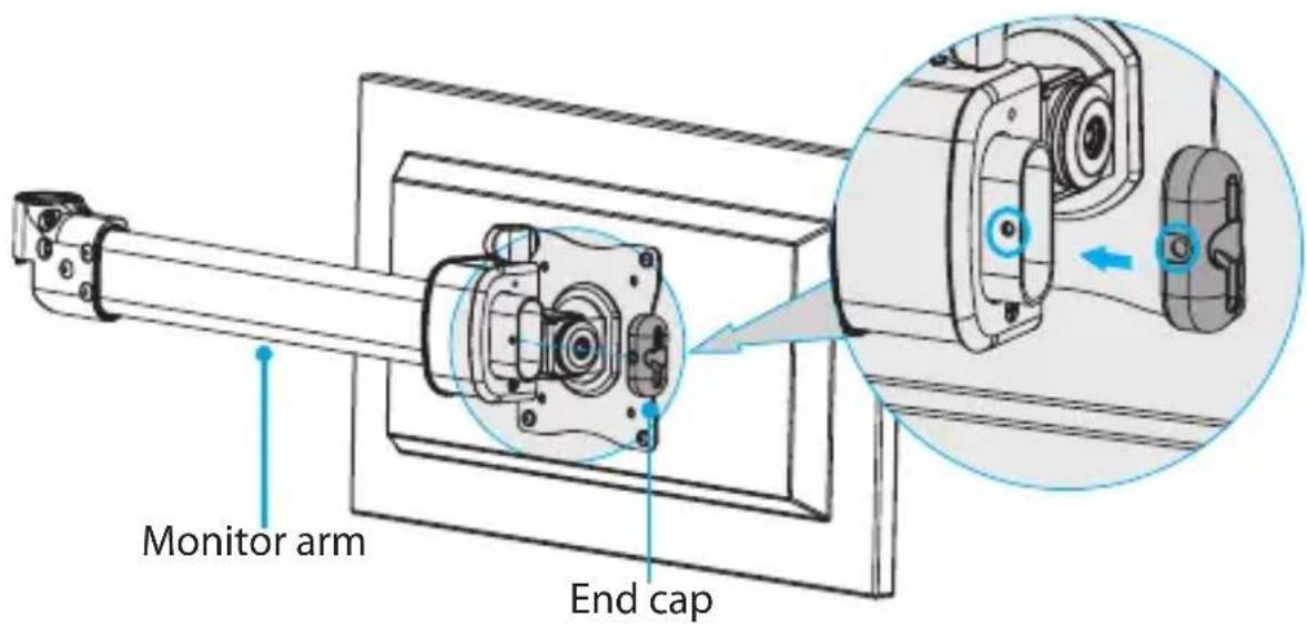
- Place an end cap on the end of each of the monitor arms. (figure 6)
Note: Make sure that you line up the hole on the end cap with the corresponding hole on the end of the monitor arms.
figure 6
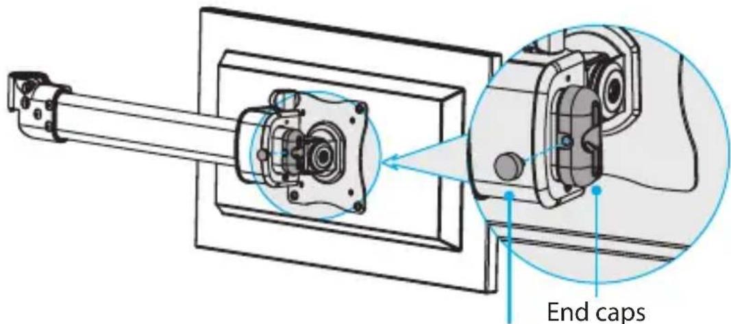
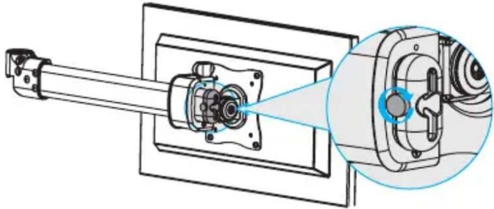
- Insert a thumbscrew through the hole in each of the end caps and into the monitor arms, and tighten the thumbscrews in place. (figure 7)
figure 7
Thumbscrew
natural_image
Technical diagram of a mechanical assembly with a shaft and housing, showing internal components and a magnified inset (no text or labels)Attach the crossbar and monitor arms
Warning! Attaching the crossbar and monitor arms is a two-person job. Do not attempt to complete this task by yourself.
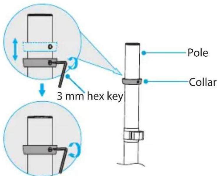
- Use the 3 mm hex key to loosen the screw in the collar on the pole.
- Slide the collar to the height that you want the monitors to sit at, and use the 3 mm hex key to tighten the screw in the collar. (figure 8)
figure 8
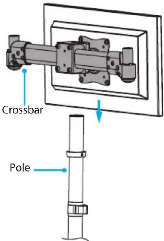
- Carefully slide the crossbar over the end of the pole so that it's sitting against the collar. (figure 9)
figure 9
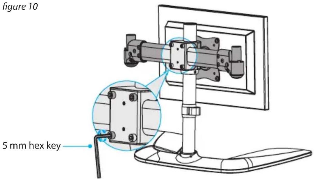
- Use the 5 mm hex key to tighten the four screws at the back of the crossbar. (figure 10)
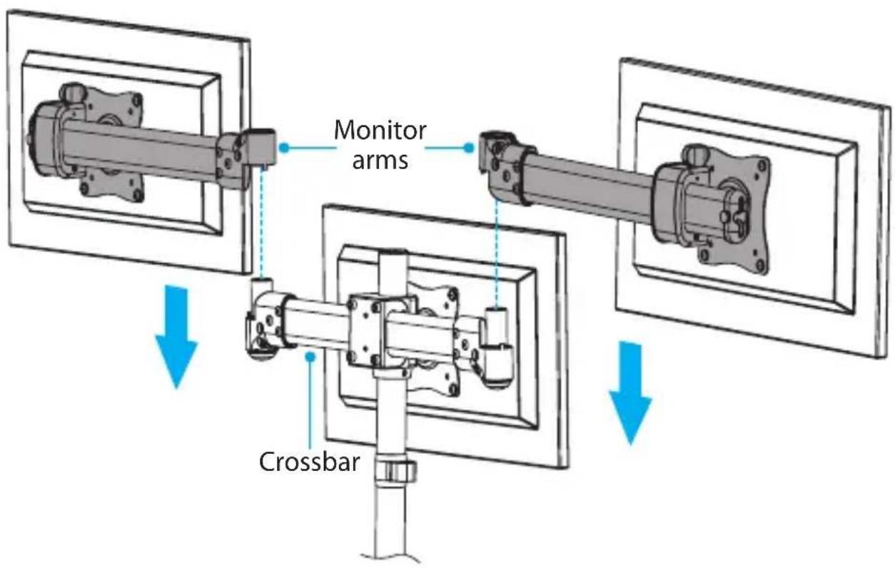
- Carefully place the left and right monitor arms over the projections on each end of the crossbar. (figure 11)
figure 11
- Place the arm caps into the two monitor arm joints. (figure 12)
figure 12
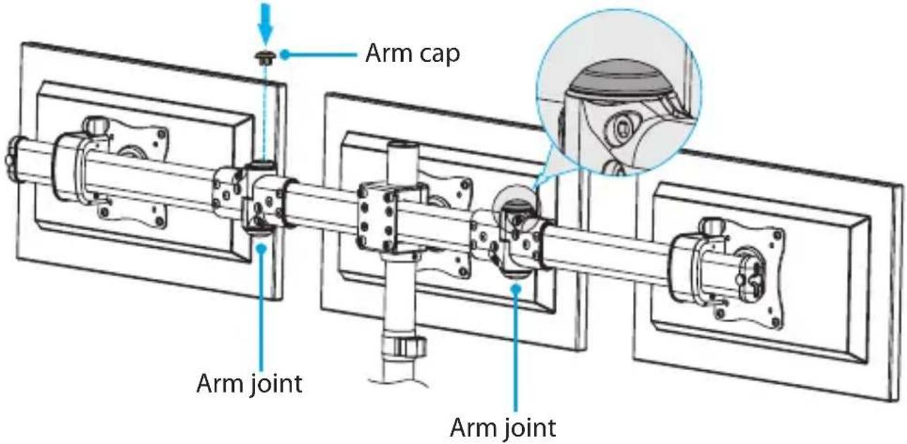
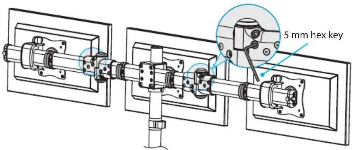
- If you're assembling the ARMBARTRIO2 for the first time, you need to tighten the two screws in the monitor arm joints. Use the 5 ~mm hex key to tighten the screws. (figure 13)
figure 13
Attach the cable-management clips
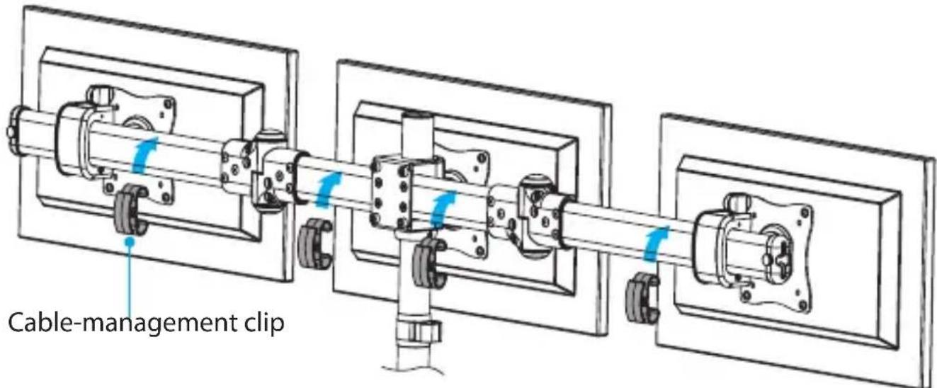
- Snap the four cable-management clips over both of the monitor arms and the crossbar. (figure 14)
figure 14
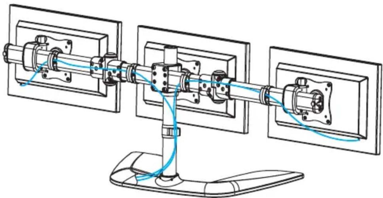
- Route the monitor cables through the cable-management clips on the monitor arms and crossbar, down the pole, and through the cable-management clip on the pole. (figure 15)
figure 15
natural_image
Technical line drawing of a mechanical assembly with blue cables connecting components (no text or symbols)Adjust the position of the monitors Tipping hazard warning
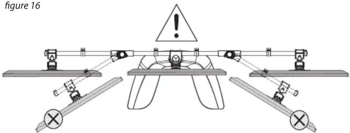
Warning! The most stable configuration of the ARMBARTRIO2 is in the "flat" position with all three of the monitors positioned in a straight line. ARMBARTRIO2 can become unstable depending on how you position the monitors. If you adjust the position of the monitors, you should exercise caution and test the stability of the ARMBARTRIO2 before you use it in the adjusted configuration. (figure 16)
You can adjust the position and angle of your monitors in the following directions:
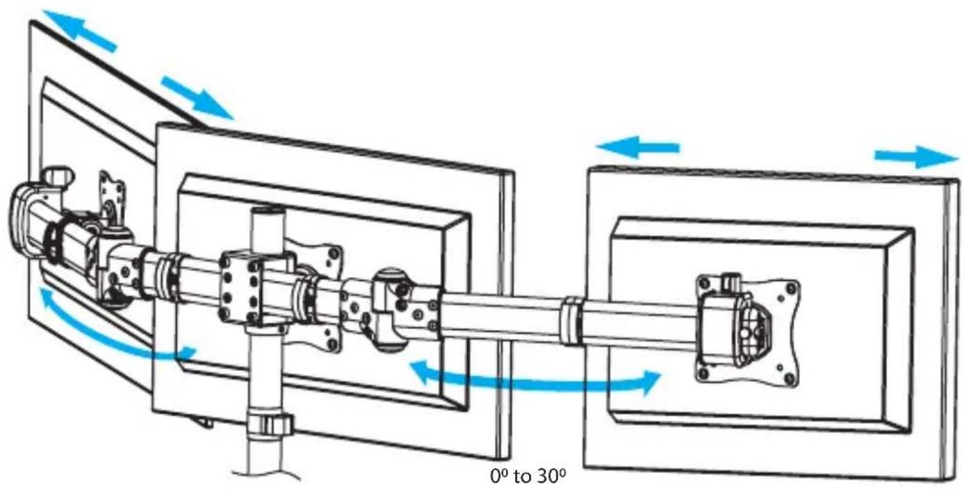
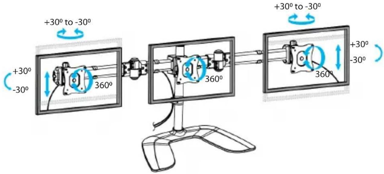
- To position the monitors in the way that works best for your setup, complete any of the following:
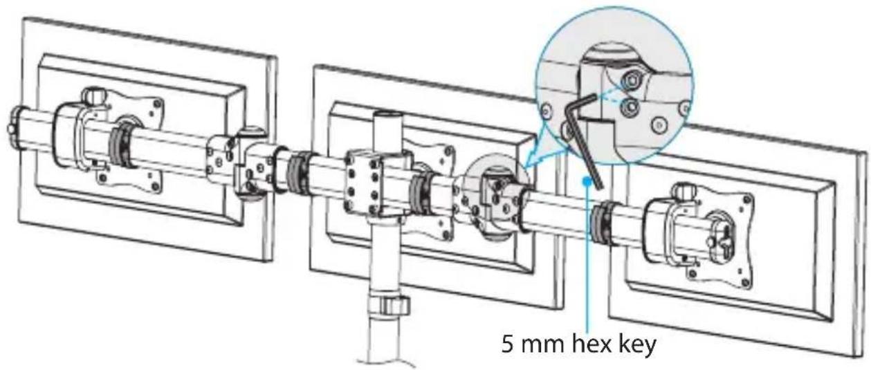
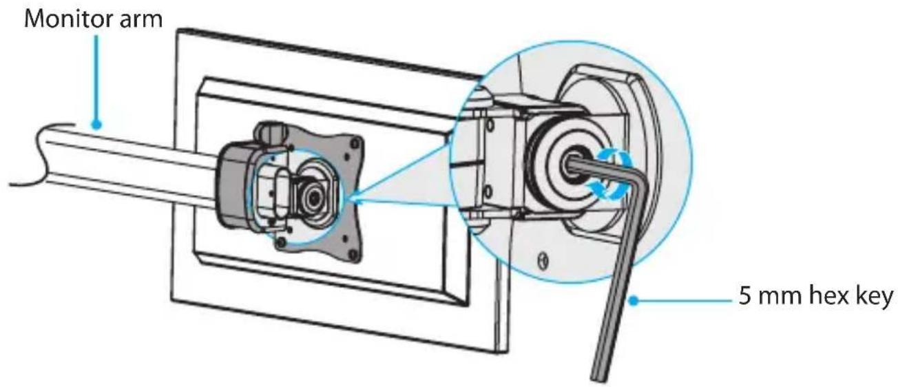
- To adjust the angle of the left and right monitor arms, use the 5 mm hex key to loosen the two screws at each of the monitor arm joints. Position the monitors at the angle that you want them in, and use the 5 mm hex key to tighten the screws. (figure 17)
figure 17
- To adjust the tilt angle of the left and right monitors, use the 5 mm hex key to loosen the screw in the sides of the VESA monitor mounts. Position the monitors at the angle that you want them in, and use the 5 mm hex key to tighten the screws. (figure 18)
figure 18
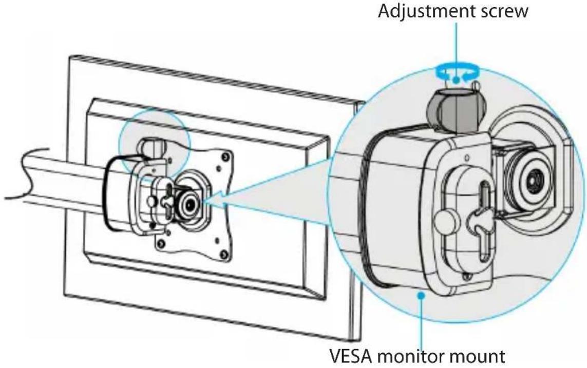
- To raise or lower the left and right monitors minutely, use the adjustment screws located on the top of the VESA monitor mounts. (figure 19)
figure 19
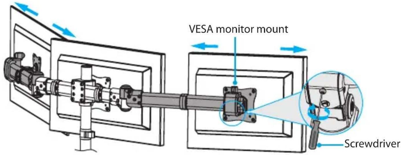
- To move the monitors along the monitor arms, use a Phillips screwdriver (not provided) to loosen the screw located on the underside of each of the VESA monitor mounts. Move the monitors left or right on the monitor arms, and tighten each of the screws when the monitors are in the locations that you want them in. (figure 20)
Warning! Make sure that you loosen the screw on the underside of the VESA monitor mounts before you move them along the monitor arms. If you move the VESA monitor mounts without loosening the screws, you might damage the surface of the monitor arms.
figure 20
Technical support
StarTech.com's lifetime technical support is an integral part of our commitment to provide industry-leading solutions. If you ever need help with your product, visit www.startech.com/support and access our comprehensive selection of online tools, documentation, and downloads.
For the latest drivers/software, please visit www.startech.com/downloads
Warranty information
This product is backed by a five-year warranty.
StarTech.com warrants its products against defects in materials and workmanship for the periods noted, following the initial date of purchase. During this period, the products may be returned for repair, or replacement with equivalent products at our discretion. The warranty covers parts and labor costs only. StarTech.com does not warrant its products from defects or damages arising from misuse, abuse, alteration, or normal wear and tear.
Limitation of liability
In no event shall the liability of StarTech.com Ltd. and StarTech.com USA LLP (or their officers, directors, employees or agents) for any damages (whether direct or indirect, special, punitive, incidental, consequential, or otherwise), loss of profits, loss of business, or any pecuniary loss, arising out of or related to the use of the product exceed the actual price paid for the product. Some states do not allow the exclusion or limitation of incidental or consequential damages. If such laws apply, the limitations or exclusions contained in this statement may not apply to you.
Hard-to-find made easy. At StarTech.com, that isn't a slogan. It's a promise.
StarTech.com is your one-stop source for every connectivity part you need. From the latest technology to legacy products — and all the parts that bridge the old and new — we can help you find the parts that connect your solutions.
We make it easy to locate the parts, and we quickly deliver them wherever they need to go. Just talk to one of our tech advisors or visit our website. You'll be connected to the products you need in no time.
Visit www.startech.com for complete information on all StarTech.com products and to access exclusive resources and time-saving tools.
StarTech.com is an ISO 9001 Registered manufacturer of connectivity and technology parts. StarTech.com was founded in 1985 and has operations in the United States, Canada, the United Kingdom and Taiwan servicing a worldwide market.
- Triple-Monitor Stand
- Use of Trademarks, Registered Trademarks, and other Protected Names and Symbols
- Warning statements
- Warnhinweise
- Product diagram
- Product dimensions
- Technical specifications
- Package contents
- Requirements
- Assembling the triple-monitor stand
- Assemble the base
- Screw the pole into the baseplate. (figure 1)
- Use the 3 mm hex key to tighten the set screws to secure the pole to the baseplate. (figure 2)
- Attach a monitor to the crossbar
- Attach the VESA monitor mounts
- Attach the monitors to the monitor arms
- Attach the crossbar and monitor arms
- Attach the cable-management clips
- Adjust the position of the monitors Tipping hazard warning
- Technical support
- Warranty information
- Limitation of liability
Brand : StarTech.com
Model : ARMBARTRIO2
Category : Flat Screen Mount