
Serie Compact 7 V750 - Heating Baxi - Free user manual and instructions
Find the device manual for free Serie Compact 7 V750 Baxi in PDF.


| Product Type | Electric Storage Water Heater |
| Brand | Baxi |
| Model | Serie Compact 7 V750 |
| Capacity | 47 L |
| Rated Power | 2000 W |
| Rated Voltage | 220-240 V ~ 50 Hz |
| Rated Current | 8.69 A |
| Max Water Temperature | 75°C |
| Protection Class | Class I |
| Waterproof Index | IPX4 |
| Empty Weight | 25.86 kg |
| Height (B) | 860 mm |
| Diameter (A) | 470 mm |
| Energy Efficiency Class | B |
| Annual Energy Consumption | 1304 kWh |
| Water Heating Efficiency | 39% |
| Sound Power Level | 15 dB |
| Heating Modes | 6 modes: 800W, 1600W, Energy Saving (55°C), Smart, Anti-legionella (80°C), Reservation (2-23h) |
| Safety Features | Thermal cut-out, thermostat, pressure relief valve, anti-scald thermostatic valve required |
| Installation | Wall-mounted, requires qualified professional |
| Maintenance | Operate safety valve yearly, descale every 2 years, clean casing with damp cloth |
| Warranty | Contact manufacturer, void if not serviced annually |
| Environmental Disposal | Comply with local regulations |
Frequently Asked Questions - Serie Compact 7 V750 Baxi
User questions about Serie Compact 7 V750 Baxi
0 question about this device. Answer the ones you know or ask your own.
Ask a new question about this device
Download the instructions for your Heating in PDF format for free! Find your manual Serie Compact 7 V750 - Baxi and take your electronic device back in hand. On this page are published all the documents necessary for the use of your device. Serie Compact 7 V750 by Baxi.
USER MANUAL Serie Compact 7 V750 Baxi
natural_image
White BAXI water heater with digital display showing temperature and humidity (no text or symbols on body)natural_image
Technical line drawing of a cylindrical tank with labeled dimension C (no text or symbols beyond basic geometry)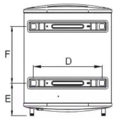
| V750 | V780 | V710 | |
| A | 470 | 570 | 570 |
| B | 860 | 900 | 1090 |
| C | 272 | 314 | 314 |
| D | 355 | 415 | 415 |
| E | 183 | 265 | 265 |
| F | 470 | 365 | 550 |
natural_image
Technical line drawing of a mechanical assembly with hatched background and bracket (no text or symbols)
natural_image
Cross-sectional diagram of a mechanical component with hatched fill (no text or symbols)Fig. 4
natural_image
Line drawing of a cylindrical water heater with labeled ports (no text or symbols beyond labels 1 and 2)Fig. 5
Hilo azul (N): Neutro
Hilo verde/amarillo: Tierra
natural_image
White BAXI water heater with digital display showing temperature and humidity (no text or symbols on body)natural_image
Technical line drawing of a cylindrical tank with labeled dimension C (no text or symbols beyond the label)
| V750 | V780 | V710 | |
| A | 470 | 570 | 570 |
| B | 860 | 900 | 1090 |
| C | 272 | 314 | 314 |
| D | 355 | 415 | 415 |
| E | 183 | 265 | 265 |
| F | 470 | 365 | 550 |
natural_image
Technical line drawing of a mechanical assembly with hatched background and structural components (no text or symbols)
natural_image
Cross-sectional diagram of a mechanical component with hatched fill and internal shaft (no text or symbols)Fig.4
natural_image
Line drawing of a cylindrical water heater with labeled parts 1 and 2 (no text or symbols on the body)Fig.5
Fio azul (N): Neutro
Fio verde/amarelo: Terra
Installation and Service Manual
For Models: Serie Compact 7 V750
Serie Compact 7 V780
Serie Compact 7 V710

natural_image
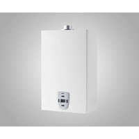
White BAXI water heater with digital display showing temperature and humidity (no text or symbols on body)The diagram above is just for reference. Please take the appearance of the actual product as the standard.
ES
PT
EN
General Remark
- The installation and maintenance must be carried out by a qualified professional or authorized technician.
- The manufacturer shall not be taken as responsible for any damage or malfunction caused by wrong installation or failing to comply with following instructions included in this manual.
- For more detailed installation and maintenance guidelines, please refer to chapters hereafter.
Safety symbols used in the manual
This manual uses various danger levels to draw attention to special instructions. We do this to improve user safety, to prevent problems and to guarantee correct operation of the appliance.
 | DangerRisk of dangerous situations that may result in serious personal injury. |
 | Danger of electric shockRisk of electric shock. |
 | WarningRisk of dangerous situations that may result in minor personal injury. |
 | CautionRisk of material damage. |


Important
Please note: important information.
See
Reference to other manuals or pages in this manual.
1 SAFETY 52
2 TECHNICAL SPECIFICATIONS 55
3 INSTALLATION 57
4 COMMISSIONING 63
5 MAINTENANCE 65
6 TROUBLESHOOTING 66
7 ENERGY EFFICIENCY 67
8 ENVIRONMENTAL 70
9 WARRANTY 70
1 SAFETY
1.1 General safety instructions

DANGER
This appliance cannot be used by children below 3 years old.
Children aged from 3 to 8 years old are only allowed to operate the tap connected to the water heater.
This appliance can be used by persons with reduced physical, sensory, or mental capabilities or lack of experience and knowledge when they have been given supervision or instruction concerning the safe use of the device and understand the resulting risks.
Children must not be allowed to play with the appliance. Cleaning and user maintenance must not be carried out by children without supervision.
Before any work, switch off the main power supply of the electrical water heater.

CAUTION
Draining the domestic hot water tank:
- Shut off the domestic cold-water inlet
- Open a hot water tap in the installation
- Open a valve on the safety unit
- When the water stops flowing, the domestic hot water tank is drained

CAUTION
The pressure relief device (safety valve or safety unit) must be periodically operated to remove limescale deposits and ensure that it is not blocked.
A pressure relief device must be fitted to a water drainpipe. As water may flow out of the water drainpipe from the pressure relief device, the pipe must be kept open to the air, in a frost-free environment, and at a continuous downward gradient.
A pressure reducer (not provided) is required when the supply pressure exceeds 80% of the pressure limiter device and must be located upstream of the appliance. There must be no cut-off devices between the pressure limiter device and the domestic hot water tank.
To ascertain the type, specification, and connection of the pressure limiter device, refer to the chapter 3.4.3 Connecting the Domestic Hot Water Tank present instruction's manual.

WARNING
Install the appliance in accordance with national rules for electrical and hydraulic installation. If the appliance is not wired in the factory, carry out the wiring according to the wiring diagram described in the chapter 3.5 Electrical Connections in the present instruction's manual. This appliance must be connected to the protective earth.

WARNING
Earthing must comply with the current installation standards. Earth the appliance before making any electrical connections. To connect the appliance to the mains supply, refer to the Electrical Diagrams and Electrical Connections sections in this document.

WARNING
Respect the minimum and maximum water pressure and temperature to ensure the appliance operates correctly, see section on Technical Specifications and Data.

WARNING
Allow the space required to install the appliance correctly, referring to the chapter Installation instructions.

WARNING
A disconnection device must be fitted to the permanent pipes in accordance with installation rules.

WARNING
If a power supply cable comes with the appliance and it turns out to be damaged, it must be replaced by the manufacturer, its after sales service or persons with similar qualifications to obviate any danger.

CAUTION
To prevent any danger owing to the unexpected reset of the thermal circuit breaker, this appliance must not be powered through an external switch, such as a timer, or be connected to a circuit which is regularly switched on and off by the electricity provider.

WARNING
Check the maximum water inlet pressure to ensure correct operation of the appliance, refer to the chapter Technical Specifications.

WARNING
To limit the risk of being scalded, the installation of a thermostatic mixing valve on the domestic hot water flow pipes is obligatory.

CAUTION
The system must satisfy each point of the rules in force in the country that govern works and interventions in individual homes, blocks of flats or other buildings.

IMPORTANT
The user guide can also be found on our website.

WARNING
This water heater has a thermostat setting up to 75^ C able to limit legionella proliferation. Installation of a thermostatic valve is mandatory to prevent the risk of water scalding users.
1.2 Recommendations

CAUTION
To benefit from extended warranty cover, no modifications must be made to the appliance.
i IMPORTANT
Keep this document close to the place where the appliance is installed.
i IMPORTANT
Never remove or cover labels and data plates fixed to the appliances. Labels and data plates must be legible throughout the entire lifetime of the appliance. Damaged or illegible instructions and warning stickers must be replaced immediately.
i IMPORTANT
Always keep the electrical water heater accessible.
1.3 Liabilities
1.3.1 Manufacturer's liability
Our products are manufactured in compliance with the requirements of the various Directives applicable. They are therefore delivered with the CE marking and any documents necessary. In the interests of the quality of our products, we strive constantly to improve them. We therefore reserve the right to modify the specifications given in this document. Our liability as manufacturer may not be invoked in the following cases:
- Failure to abide by the instructions on installing and maintaining the appliance
- Failure to abide by the instructions on using the appliance
- Faulty or insufficient maintenance of the appliance
1.3.2 Installer's liability
The installer is responsible for the installation and initial commissioning of the appliance. The installer must observe the following instructions:
- Read and follow the instructions given in the manuals provided with the appliance
• Install the appliance in compliance with prevailing legislation and standards - Carry out initial commissioning and any checks necessary
- Explain the installation to the user
- For the maintenance of this product, warn the user of the obligation to check the appliance and keep it in good working order
- Give all the instruction manuals to the user
1.3.3 User's liability
To guarantee optimum operation of the system, the user must abide by the following instructions:
- Read and follow the instructions given in the manuals provided with the appliance
- Call on a qualified professional to carry out installation and initial commissioning.
- Ask your installer to explain your installation to you
- Have the required inspections and maintenance carried out by a qualifies installer
- Keep the instruction manuals in good condition close the appliance.
2 TECHNICAL SPECIFICATIONS
2.1 Homologations
2.1.1 EC Declaration of Conformity
The unit complies with the standard type described in the EC declaration of conformity. It has been manufactured and commissioned in accordance with European directives. The original declaration of conformity is available from the manufacturer.
2.1.2 Electrical Conformity / CE Marking
This product complies with the requirements of the following European Directives and Standards:
- Low Voltage Directives 2014/35/EU: Generic standard: EN 60335-1 Relevant standards: EN 60335-2-21
• Electromagnetic Compatibility Directive 2014/30/EU:
Generic standards: EN 55014-1
EN 55014-2
Relevant Standard: EN 61000-3-2
EN 61000-3-3
EN 61000-6-1
EN 61000-6-3
2.1.3 2014/68/UE Pressure Equipment Directive
This product conforms to the requirements of European Directive 2014/68/UE, article 4, paragraph 3, on pressure equipment.
2.1.4 Eco-design Directive
This product conforms to the requirements of European Directive 2009/125/EC on the eco-design of energy-related products.
2.2 Technical Data
| Item | V750 | V780 | V710 |
| Volume (L) | 47 | 74 | 93 |
| Rated Power (W) | 2000 | 2000 | 2000 |
| Rated Voltage (V) | 220-240 | 220-240 | 220-240 |
| Rated Pressure (MPa) | 0.8 | 0.8 | 0.8 |
| Max Of Water Temperature (°C) | 75 75 75 | ||
| Protection Class | I | I | I |
| Waterproofness Index | IPX4 | IPX4 | IPX4 |
| Weight of Empty Product (kg) | 25.86 | 32.45 | 38.38 |
| Rated Intensity (A) | 8.69 | 8.69 | 8.69 |
2.3 Dimensions
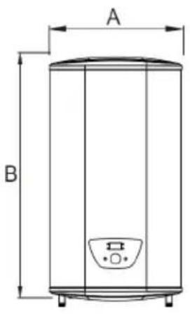

natural_image
Technical line drawing of a cylindrical tank with labeled dimension C (no text or symbols beyond basic geometry)
| V750 | V780 | V710 | |
| A | 470 | 570 | 570 |
| B | 860 | 900 | 1090 |
| C | 272 | 314 | 314 |
| D | 355 | 415 | 415 |
| E | 183 | 265 | 265 |
| F | 470 | 365 | 550 |
Note: all dimensions are in mm
2.4 Electrical Diagram
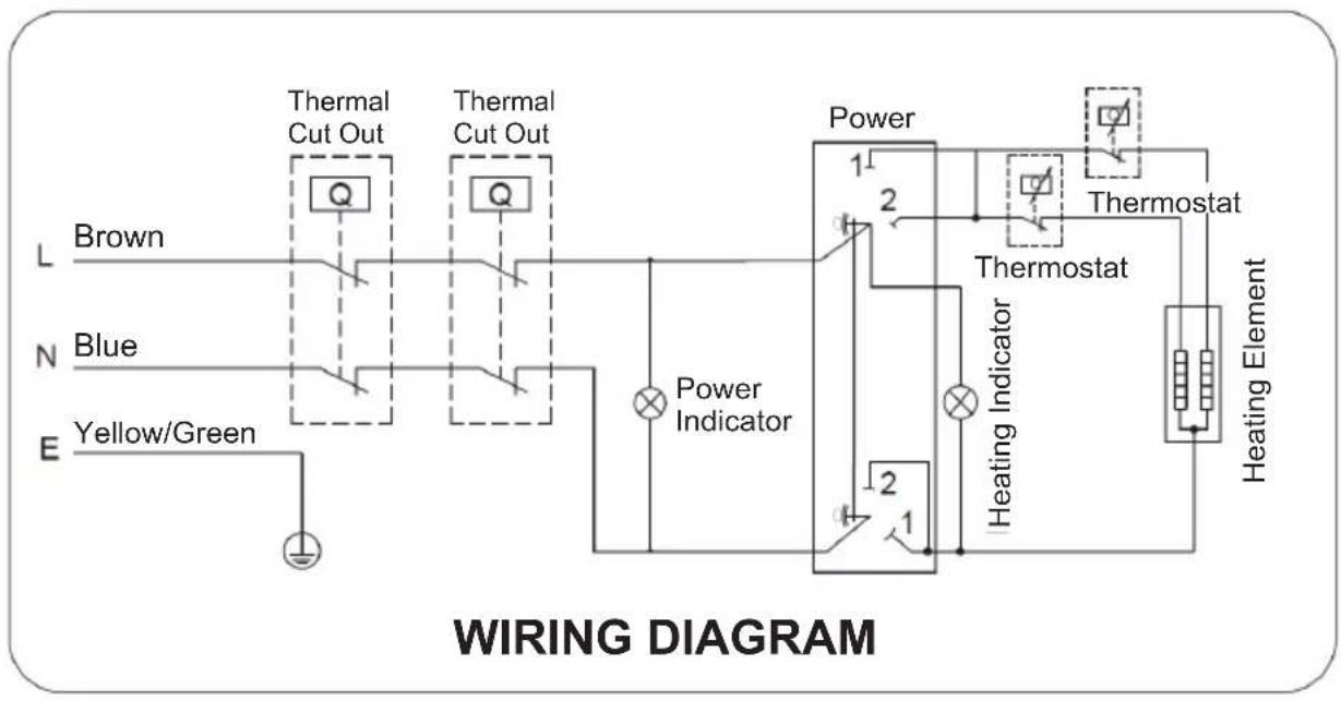
flowchart
graph TD
    A["Brown"] --> B["Thermal Cut Out"]
    C["Blue"] --> D["Thermal Cut Out"]
    E["Yellow/Green"] --> F["Power Indicator"]
    B --> G["Thermostat"]
    D --> G
    F --> H["Heating Indicator"]
    G --> I["Thermostat"]
    H --> J["Heating Element"]
    style A fill:#f9f,stroke:#333
    style C fill:#f9f,stroke:#333
    style E fill:#f9f,stroke:#333
    style G fill:#ccf,stroke:#333
    style H fill:#ccf,stroke:#333
    style I fill:#ccf,stroke:#333
    style J fill:#ccf,stroke:#333
3 INSTALLATION
3.1 Position of the data plates
The data plates must be always accessible, they are used to identify the product and give the following information:
- Appliance type,
- Serial number,
• Electrical power supply.

Fig.1
3.2 General recommendations
The appliances must be installed by a certified professional in accordance with prevailing statutory texts and codes of practice. The installation must comply on all points with prevailing regulations and directives, which govern work and interventions in individual homes, blocks of flats and other buildings
3.3 Installation Instruction
In a bathroom, do not install this product in Volumes V0 and V1 (see Fig.2).
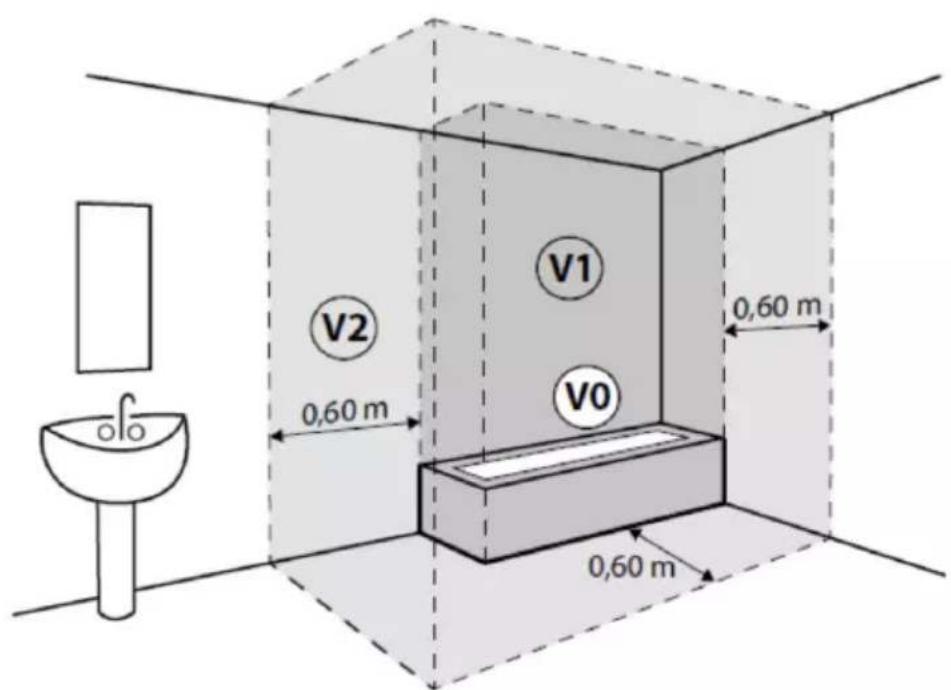
Fig.2
If the water heater is installed above habitable premises, provide a storage tank with outflow to the drains
① This electrical water heater shall be installed on a solid wall. If the strength of the wall cannot bear the load equal to two times of the total weight of the heater filled fully with water, it is then necessary to install a special support. In case of hollow bricks wall, fill with cement concrete completely.
② After selecting a proper location, determine the positions of the two install holes used for expansion bolts with hook, Drill two holes in the wall with the corresponding depth by using a chopping bit with the size matching the expansion bolts attached with the machine, insert the screws, make the hook upwards, tighten the nuts to fix firmly, and then hang the electrical water heater on it (see Fig.3).

natural_image
Technical line drawing of a mechanical assembly with hatched background and bracket (no text or symbols)
natural_image
Cross-sectional diagram of a mechanical component with hatched fill (no text or symbols)Expansion bolt (with hook)
Fig.3
3.4 Recommendations and obligations
3.4.1 Connecting diagram

Fig.4
- Domestic hot-water outlet with dielectric union
- Domestic cold-water inlet with dielectric union
- Power supply cable for the immersion heater
- Thermostatic valve
- Safety unit
- Pressure reducer
natural_image
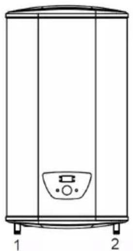
Line drawing of a cylindrical water heater with labeled ports (no text or symbols beyond labels 1 and 2)Fig.5
- Domestic hot water outlet (red color)
- Domestic cold-water inlet (blue color)
The components used for the connection to the cold-water circuit must comply with the prevailing standards and regulations in the country concerned. The water connections must comply with the corresponding standards and local directives.
The domestic hot water circuits and cold-water feed pipes must be rinsed before making any water connections to prevent metal particles or other contaminants into the domestic hot water tank. If rinsing must be done using an aggressive product, neutralize the rinsing water before disposing of it in the wastewater network.
3.4.2 Connecting the domestic hot water tank
The dielectric unions are provided in the documentation bag.
- A dielectric union must be connected using hemp fiber or pipe joint compound, between the water outlet/inlet of the domestic hot water tank and the pipework to avoid any corrosion at the union.

- It is mandatory to mount a domestic water thermostatic mixing valve (not provided) on the domestic hot water tank outlet.
3.4.3 Connecting the domestic hot water circuit
- Install a pressure reducer if the mains pressure exceeds 80% of the calibration of the safety valve or unit (e.g., 0.6 MPa / 6 bar) for a safety unit calibrated to 0.8 MPa / 8 bar).

Caution
Install the pressure reducer upstream of the appliance and downstream of the water meter in such a way as to ensure the same pressure in all the system's pipes.
- Install a water drain in the boiler room and a funnel-siphon for the safety unit.
- Incorporate a sealed safety valve calibrated to 0.8 MPa (8 bar) on the domestic cold-water inlet, close to the tank, in a position which is easy to reach, to protect the domestic hot water tank from pressure surges.

Caution
There must be no cut-off devices between the safety valve or unit and the domestic hot water tank.
- To avoid restricting the flow of water in the event of overpressure: the safety unit discharge pipe must be kept in the open, in a frost-free environment, and have a continuous, downward gradient; the diameter of the safety unit and its connection to the tank must be at least equal to the diameter of the domestic cold-water inlet on the tank.
- Make the connection to the domestic cold water.
3.4.4 Fill the domestic hot water tank.
When the water and electrical connections are made, fill the domestic hot water tank.
- Turn on a hot water tap.
- Open the cold-water tap located on the safety unit to vent the air in the installation.
-
Close the hot water tap when water starts to flow from the tap. The domestic hot water tank is full.
-
Check the tightness of the pipe connections and the correct operation of the hydraulic devices by successively opening the drain valve on the safety unit.
3.5 Electrical connections
3.5.1 Electrical recommendations
Only qualified professionals should carry out electrical connections, always with the power off. Separate the very low voltage cables from the 230 V circuit cables. The electrical power supply is done by means of a mains connection cable (\~230 V, 50 Hz) in accordance with prevailing national regulations for electrical installations. Respect the polarities when making the electrical connections to the mains:
Brown wire (L): Line
Blue wire (N): Neutral
Green/yellow wire: Earth
If the power supply cable is damaged, you must have it replaced by a qualified installer. The 2.5 mm ^2 section power supply cable for the electrical connection of the domestic hot water tank must be used by the installer.
3.5.2 Electrical recommendations
Connect the power supply; the indicator will light up.
The thermostat will automatically control the temperature. When the water temperature inside the heater has reached the set temperature, it will switch off automatically, when the water temperature falls below the set point the heater will be turned on automatically to restore the heating.

Fig.6
* Electrical plug is in accordance with Spanish and Portuguese safety standards
4 COMMISSIONING
4.1 Initial commissioning
Initial commissioning must be performed by a qualified professional.
4.2 Checklist after commissioning
A few days after the appliance is commissioned, please:
- Check the installation
- Check the tightness of the connections
- Check the water pressure
- Check that there are no errors on the control panel
• Inform the user of the frequency of maintenance work to be carried out - Explain how the system and control panel work to the users
• Hand over all manuals to the user
4.3 Operating the Unit
| Mode # | Mode description | Indicator |
| 1 | 800W power heating (single tank) | Indicator 4 ON |
| 2 | 1600W power heating (both tanks) | Indicator 5 ON |
| 3 | Energy saving Active (Temp. = 55°C) | Indicator 8 ON |
| 4 | Smart control energy Active | Indicator 9 ON |
| 5 | Anti-legionella mode Active (Temp. = 80°C during 5 min) | - |
| 6 | Reservation Mode Active | Indicator 6 ON |

Fig.7
① is the on/off button, when pressed, the water heater starts working and the display screen lights up. When pressed again, electricity will be cut off, and display screen will be shut down.
② is the knob which is used to adjust the set temperature of the water heater. When entering the reservation mode, it is used to adjust the reservation time during the first 5 seconds (⑦ is flashing).
③ button is for switching mode.
⑥ displays the active mode.
If number "1" shows, it means MODE 1 (800 W, only one tank is heating), ④ will be on.
If number “2” shows, it means MODE 2 (1600 W, the two inner tanks have been being heated up), ⑤ will be on.
If number “3” shows, it means MODE 3 (energy saving mode, the temperature is set to 55^ C and cannot be adjusted), ⑧ will be on.
If number “4” shows, it means MODE 4 (smart control energy saving mode, the water temperature is automatically changed), ⑨ will be on. The appliance works to reduce the electricity energy of the user consumption, which allows heat loss to be minimized and energy savings to be maximized.
If number “5” shows, it means MODE 5 (anti-legionella mode). The fixed setting temperature is 80 degrees, and heating starts when the temperature is lower than this temperature. The heating temperature will keep 80 degrees, for 5 minutes, then exit and return to the default mode.
If character is "H", it means MODE 6 (reservation mode). The system enters the appointment hour setting mode, the digital screen displays the appointment hour time. The range can be set from 2 to 23. The knob adjusts the setting time, flashes for 5 seconds and enters the appointment mode, at this time the knob can set the temperature, the appointment is two hours in advance to exit and heat. After entering the reservation, the number of hours (⑦) and "H" (⑥) are displayed, such as "03H" means that the heating is completed after 3 hours.
There is no memory of power loss when the appointment is made, and it will automatically enter MODE 2 after the appointment is completed.
When the water heater is heating, ⑦ will be on and display the real time temperature.
4.4 Error code for serviceman's use
| Code # | Error description | Procedure |
| E2 | Dry Ashing | Fill up with water and re-heat |
| E3 | Overheating | Check the heating system or replace it |
| E4 | Sensor Fault | Check the sensor or replace it |
5 MAINTENANCE
5.1 General

Caution
Do not neglect to service the domestic hot water tank.
Contact a qualified professional or take out a maintenance contract for the obligatory annual servicing of the electrical water heater.
Failure to service the appliance voids the warranty.
The control and maintenance interventions for the appliance must be performed by a certified professional in accordance with prevailing statutory texts and codes of practice.
Maintenance operations are important for the following reasons:
• To guarantee optimum performance.
• To extend the life of the equipment.
- To provide an installation which offers the customer optimum comfort over time.
Power off the electrical water heater before any interventions on the appliance.
Remove the electrical water heater casing only to perform maintenance and repair work.
Put the casing back in place after maintenance and repair work.
5.2 Maintenance operation intervals
5.2.1 General maintenance
| Operation | Periodicity | Installer | User |
| Operate the safety valve or unit | Once a year | X |
5.2.2 Maintenance of domestic hot water tank
| Operations | Periodicity | Installer | User |
| Clean the casing using a damp soft cloth | once a year | X | |
| Descaling the domestic hot water tank | after the first year of use and then every two years | X |
5.3 Operate the safety valve or unit
To take the proper precautions against possible pressure surges which would damage the domestic hot water tank, ensure the safety valve or unit functions correctly. Failure to follow this maintenance requirement may lead to damage of the domestic hot water tank and void its warranty:
- Operate the safety valve or unit at least once a year.
- Replace the safety valve or unit if necessary
6 TROUBLESHOOTING
| Failures | Reasons | Treatment |
| The heating indicator light is off. | Failure of temperature controller | To contact a professional for repair |
| No water coming out of the hot water outlet | 1. The running water supply is cut off2. The hydraulic pressure is too low3. The inlet valve of running water is not open | 4. Wait for restoration of running water supply5. Use the heater again when the hydraulic pressure is increased6. Open the inlet valve of running water |
| Water temperature is too high | Failure of the temperature control system | Contact with the professional personnel for repair |
| Water leakage Seal problem of the joint of each pipe | Seal up the joints | |
7 PRODUCTS ENERGY RELATED TO EU REGULATION
7.1 50 Liters product energy efficiency
The electrical storage water heater V750 of the company BAXI, a company fully owned by BDR Thermea Group B.V was tested with a declared load profile of the size "M".
The product fulfills and corresponds to the requirements of the commission regulation standards (No 814/2013) for electrical storage water heater and achieved a water heating energy efficiency of wh = 39% corresponding to the water heating efficiency class "B".
The sound power level is 15dB.
In accordance with Annex II Energy Efficiency Classes article 1 of the commission regulation (No 812/2013).
The evaluation of the result of this report with respect of conformity with the related commission regulation (No 812/2013 and 814/2019) is only a part of the conformity assessment to achieve the ErP Label.
Electricity consumption Q_elec , water heating energy efficiency _wh and mixed water at 40^ (V40).
| Description | Parameter | Value | Unit |
| Storage volume | V | 47 | L |
| Water heating energy efficiency * | _wh | 39 | % |
| Annual Electricity Consumption * | AEC | 1304 | kWh |
| Water heating energy efficiency class * | B | ||
| Calculated volume that delivered hot water of at least 40°C according to EN 50440 | V40 77 L | ||
| The thermostat temperature setting of the water heater, as placed on the market by the supplier | 75°C | ||
| Specific precautions that shall be taken when the water heater is assembled, installed or maintained and disposed of at end of life. | See section 3 to 5 | ||
| * The information on the water heating energy efficiency and annual electricity relate to enabled smart control settings only. | |||
7.2 80 Liters product energy efficiency
The electrical storage water heater V780 of the company BAXI, a company fully owned by BDR Thermea Group B.V was tested with a declared load profile of the size "M".
The product fulfills and corresponds to the requirements of the commission regulation standards (No 814/2013) for electrical storage water heater and achieved a water heating energy efficiency of wh = 39% corresponding to the water heating efficiency class "B".
The sound power level is 15dB.
In accordance with Annex II Energy Efficiency Classes article 1 of the commission regulation (No 812/2013).
The evaluation of the result of this report with respect of conformity with the related commission regulation (No 812/2013 and 814/2019) is only a part of the conformity assessment to achieve the ErP Label.
Electricity consumption Q_elec , water heating energy efficiency _wh and mixed water at 40^ (V40).
| Description | Parameter | Value | Unit |
| Storage volume | V | 74 | L |
| Water heating energy efficiency * | _wh | 39 | % |
| Annual Electricity Consumption * | AEC | 1307 | kWh |
| Water heating energy efficiency class * | B | ||
| Calculated volume that delivered hot water of at least 40°C according to EN 50440 | V40 113 | L | |
| The thermostat temperature setting of the water heater, as placed on the market by the supplier | 75°C | ||
| Specific precautions that shall be taken when the water heater is assembled, installed or maintained and disposed of at end of life. | See section 3 to 5 | ||
| * The information on the water heating energy efficiency and annual electricity relate to enabled smart control settings only. | |||
7.3 100 Liters product energy efficiency
The electrical storage water heater V710 of the company BAXI, a company fully owned by BDR Thermea Group B.V was tested with a declared load profile of the size "M".
The product fulfills and corresponds to the requirements of the commission regulation standards (No 814/2013) for electrical storage water heater and achieved a water heating energy efficiency of _wh = 39% corresponding to the water heating efficiency class "B".
The sound power level is 15dB.
In accordance with Annex II Energy Efficiency Classes article 1 of the commission regulation (No 812/2013).
The evaluation of the result of this report with respect of conformity with the related commission regulation (No 812/2013 and 814/2019) is only a part of the conformity assessment to achieve the ErP Label.
Electricity consumption Q_elec , water heating energy efficiency _wh and mixed water at 40^ (V40).
| Description | Parameter | Value | Unit |
| Storage volume | V | 93 | L |
| Water heating energy efficiency * | _wh | 39 | % |
| Annual Electricity Consumption * | AEC | 1301 | kWh |
| Water heating energy efficiency class * | B | ||
| Calculated volume that delivered hot water of at least 40°C according to EN 50440 | V40 161 | L | |
| The thermostat temperature setting of the water heater, as placed on the market by the supplier | 75°C | ||
| Specific precautions that shall be taken when the water heater is assembled, installed, maintained, and disposed of at end of life. | See section 3 to 5 | ||
| * The information on the water heating energy efficiency and annual electricity relate to enabled smart control settings only. | |||
8 ENVIRONMENTAL
Disposal and recycling
(Fig.8)

Warning
Removal and disposal of the water heater must be carried out by a qualified installer in accordance with local and national regulations.
9 WARRANTY
9.1 General
We would like to thank you for buying one of our appliances and for your trust in our product.
To ensure continued safe and efficient operation, we recommend that the product is regularly inspected and maintained.
Your installer and our service department can assist with this.
BAXI
Tel. +34 902 89 80 00
www.baxi.es
informacion@baxi.es



CE
BAXI

- Installation and Service Manual
- General Remark
- Safety symbols used in the manual
- Important
- See
- SAFETY
- General safety instructions
- DANGER
- CAUTION
- WARNING
- Recommendations
- i IMPORTANT
- Liabilities
- Manufacturer's liability
- Installer's liability
- User's liability
- TECHNICAL SPECIFICATIONS
- Homologations
- EC Declaration of Conformity
- Electrical Conformity / CE Marking
- 2014/68/UE Pressure Equipment Directive
- Eco-design Directive
- Technical Data
- Dimensions
- Electrical Diagram
- INSTALLATION
- Position of the data plates
- General recommendations
- Installation Instruction
- Recommendations and obligations
- Connecting diagram
- Connecting the domestic hot water tank
- Connecting the domestic hot water circuit
- Fill the domestic hot water tank.
- Electrical connections
- Electrical recommendations
- Electrical recommendations
- COMMISSIONING
- Initial commissioning
- Checklist after commissioning
- Operating the Unit
- Error code for serviceman's use
- MAINTENANCE
- General
- Maintenance operation intervals
- General maintenance
- Maintenance of domestic hot water tank
- Operate the safety valve or unit
- TROUBLESHOOTING
- PRODUCTS ENERGY RELATED TO EU REGULATION
- 50 Liters product energy efficiency
- 80 Liters product energy efficiency
- 100 Liters product energy efficiency
- ENVIRONMENTAL
- WARRANTY
- General
Brand : Baxi
Model : Serie Compact 7 V750
Category : Heating