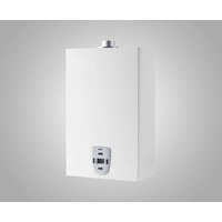
11Fi Blue - Heating Baxi - Free user manual and instructions
Find the device manual for free 11Fi Blue Baxi in PDF.


| Product Type | Gas condensing boiler |
| Brand | Baxi |
| Model | 11Fi Blue |
| Energy Source | Natural gas / LPG |
| Heating Output (max) | 24 kW |
| Efficiency (condensing) | Up to 94% (seasonal) |
| Dimensions (H x W x D) | 700 x 400 x 300 mm |
| Weight | 30 kg |
| Power Supply | 230 V / 50 Hz |
| Max Water Pressure | 3 bar |
| Temperature Range | 30°C - 80°C |
| Safety Features | Flame failure, overheat protection, frost protection |
| Noise Level | < 50 dB(A) |
| Maintenance | Annual service recommended |
| Warranty | 2 years (parts and labor) |
| Mounting | Wall-mounted |
| Flue Type | Room-sealed (balanced flue) |
| Energy Class | A |
Frequently Asked Questions - 11Fi Blue Baxi
User questions about 11Fi Blue Baxi
0 question about this device. Answer the ones you know or ask your own.
Ask a new question about this device
Download the instructions for your Heating in PDF format for free! Find your manual 11Fi Blue - Baxi and take your electronic device back in hand. On this page are published all the documents necessary for the use of your device. 11Fi Blue by Baxi.
USER MANUAL 11Fi Blue Baxi
natural_image
Technical line drawing of a mechanical assembly with a central component and mounting base (no text or symbols)This appliance is manufactured in accordance with the rules of good practice in compliance with current legislation.
The CE mark on the product means that it conforms to the following European Directives:
• Regulation Gas Appliance (UE) 2016/426
• Low voltage directive 2014/35/UE
• Electromagnetic compatibility directive 2014/30/UE
• European Standard: gas-fired instantaneous water heaters for the production of domestic hot water EN 26
• Ecodesign directive for energy-related products 2009/125/EC
• Regulation (EU) 2017/1369 setting a framework for energy labelling
• Delegated regulation (EU) no 812/2013
• Delegated regulation (EU) no 814/2013


When the product has reached the end of its serviceable life, it shall be disposed of in an environmentally friendly way and disposed of according to the regulations in force.
Separate collection and recycling of the product avoid negative impact for environment and health, and allows recovery of materials, in order to obtain energy and resources saving.
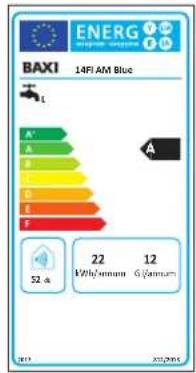
The appliance complies with the Regulation (EU) 2017/1369 setting a framework for energy labelling.
The energy label carries the information regarding the product's energy efficiency characteristics.
In this way the end consumer can identify and compare similar products and can make informed choices regarding high efficiency appliances.
PRODUCT DATA SHEET
| BAXI | 14Fi AM Blue | 17Fi AM Blue | |
| Declared load profile | L | XL | |
| Internal sound power level | dB(A) 52 | 56 | |
| Water heating energy efficiency class | A | A | |
| Water heating energy efficiency | % 76 | 80 | |
| Annual fuel consumption | GJ 12 | 19 | |
| Annual consumption of electric energy | kWh 22 | 28 | |
| Nitrogen oxide emissions G20-G30-G31 | mg/kWh 4 | 0-61-36 | 44-56-35 |

DESCRIPTION OF THE SYMBOLS USED IN THE MANUAL AND ON THE PACKAGING
 | Actions that require particular care and adequate preparation |
 | Actions that MUST NOT be performed |
 PAP PAP | Recyclable packing material |
 | Do not clamp |
 | High |
 | Affected by humidity |
 | Fragile |
 | Max 4 |
WARNING
This manual contains data and information for both the user and the installer.
Specifically, the user must pay attention to the chapters:
General warnings and safety devices, Control panel and Use of the appliance.
A number of symbols are used In some parts of the manual:

ATTENTION = for actions that require particular care and adequate preparation

PROHIBITED = for actions that MUST NOT be performed
ATTENTION
To preserve the life and efficiency of the appliance, it is compulsory to install a polyphosphate dispenser in the presence of water whose characteristics could result in the formation of mineral deposits.
According to Italian Presidential Decree 59/09 it is necessary to treat the water supply with temporary hardness greater than or equal to 25 French degrees for the heating circuit and greater than or equal to 15 French degrees for domestic water through chemical treatment (according to UNI 8065) of conditioning for powers ≤ 100 kW or softening for powers > 100 kW.
Failure to comply with the above entails cancellation of the warranty.
TABLE OF CONTENTS
GENERAL WARNING AND SAFETY DEVICES p. 17
DESCRIPTION OF THE APPLIANCE p. 17
| INSTALLATION “ 18 | |
| Regulations | “ 18 |
| Wall mounting | “ 18 |
| Support bracket | “ 18 |
| Electrical connection | “ 18 |
| Gas connection | “ 18 |
| Water connection | “ 19 |
| Evacuation of combustion products | “ 19 |
| Warnings before ignition | “ 20 |
| Checking the system pressure | “ 20 |
| Gas conversion | “ 20 |
USE OF THE APPLIANCE "21
| Preliminary checks | “ | 21 |
| Appliance start-up | “ | 21 |
| Water temperature adjustment | “ | 21 |
| Switching off the appliance | “ | 22 |
SERVICE MENU "22
| Parameters menu | “ | 22 |
| Calibration menu Manu | “ | 22 |
| Alarm hystorical menu | “ | 23 |
| Info menu | “ | 23 |
ANOMALIES AND DISPLAY VIEWS "23
| MAINTENANCE | “ 25 |
TECHNICAL DATA " 26
QUICK-START GUIDE

POWER ON
Press the power ON button ⏻
WATER TEMPERATURE ADJUSTMENT
Press button to increase and to decrease the water temperature (set between 37 and 60°C).
POWER OFF
Press and hold the on/off button. (As soon as the symbols
- - begin to flash, release the button.
The appliance will be in the OFF state, the display shows—
RESET
Press and hold the button. As soon as the display shows the wording release the button.
The appliance is available for use.
GENERAL WARNINGS AND SAFETY DEVICES
The instruction manual is an integral part of the product and must therefore be carefully stored and always accompany the appliance; in case of loss or damage, request another copy from the Technical Service Centre.

The appliance must be used as intended by the manufacturer. contractual and non-contractual liability is excluded for damage to persons, animals or property, due to installation, adjustment and maintenance errors or improper use

The installation, service and user manual constitutes an integral part as well as essential equipment of the water heater and must be retained for the entire period of use and read carefully as it contains all the information and warnings regarding safety during installation, operation and maintenance, which must be respected. In the case of transfer of the appliance to any other user, ensure it is accompanied by the installation, service and user manual

Installation of the appliance and any other intervention of service and maintenance must be performed by qualified personnel in compliance with the legislation in force and subsequent updates

For installation it is advisable to use specialist personnel

Failure to comply with the recommendations of this user manual and failure to adhere to the instructions included therein by installers and by the user will invalidate any future warranty claim

The safety or automatic adjustment devices must only, throughout the life of the system, be altered by the manufacturer

This appliance is used to produce hot water. It must therefore be connected to a domestic hot water distribution network, according to its performance and power

In case of leakages of water, close the water supply and promptly notify the qualified personnel of the Technical Service Centre

In case of prolonged absence, shut off the gas supply. Where the risk of freezing is anticipated, empty the water heater of the water contained therein

In case of failure and/or malfunction of the appliance, switch it off and do not attempt any kind of repair or direct action

Maintenance must be performed at least once a year: scheduling this with the Technical Support Centre will avoid wasting time and money

At the end of its life span the product must not be disposed of as solid urban waste but must be removed to a recycling centre

In the case of prolonged absence, shut off the gas supply. Where the risk of freezing is anticipated, empty the water heater of the water contained therein.

The casing can reach high temperatures in the burner area, with the risk of burns in the event of contact.

Contact with hot water and a temperature ≥50 ^ can cause severe burns.

It is recommended to test the temperature of hot water before using the appliance, to prevent burns.

For daily use of the product it is recommended to set the temperature at a value not exceeding 50^ C.

After installing the appliance, the installer must inform the user about the functioning of the appliance, the basic safety standards and the safety devices
Use of the appliance requires strict adherence to certain fundamental safety rules:

Do not use the appliance for purposes other than those for which it was intended

Under no circumstances cover with rags, papers or other material the inlet or dissipation grids and the ventilation shaft of the room where the appliance is installed

Where the smell of gas is perceived, refrain from using any electrical switches, telephones or any other object that could cause sparks. Ventilate the room by opening doors and windows and close the main gas valve

Do not place objects on the appliance

Do not leave containers or flammable substances in the room where the appliance is installed

Any attempt to carry out a repair in case of failure and/or malfunction of the appliance is inadvisable

The use of this appliance by children or inexperienced persons is not recommended

It is forbidden to intervene on sealed elements
To optimise use, be aware that:
- Periodic external cleaning with soapy water, as well as to improve the aesthetic appearance, protects the panelling from corrosion, extending the life of the appliance
- Do not use solvents, powders or abrasive sponges
- Do not clean the appliance and/or its parts with flammable substances (example: petrol, alcohols, oil, etc.).
The packaging of the water heater includes:
no. 1 wall mounting bracket with screws and plugs
no. 2 flange flues
no. 1 paper template
DESCRIPTION OF THE APPLIANCE
NOx identifies the group of the two most important nitrogen oxides:
- NO Nitrogen monoxide (not harmful to humans)
- NO _2 Nitrogen dioxide (very harmful to humans and the environment).
NOx is formed during combustion processes at high temperatures. To reduce NOx emissions it is necessary to cool the flame.
The water inside the water heater, after have been heated by heat exchanger, gets in the burner, cools the flame and gets out to the final user.
The special burner cools the flame and check the airflow necessary for the combustion, set up “cooled flames” avoiding the loss of thermal efficiency, generating an optimal combustion with low emissions.
INSTALLATION
Regulations

Entrust installation of the water heater to personnel with appropriate professional qualifications

Connection of the water heater to the water, gas and flue gas exhaust systems and the room where the heater is to be installed must comply with the rules and regulations in force

Following installation of the water heater, check the tightness of all the gas and water connections

Installation, gas connection, the air intake pipes/flue gas release tube installation, electrical connection and commissioning of the water heater must be entrusted to an authorised installer in accordance with the Law in force

Comply with applicable laws and regulations, with any local regulations concerning the installation of gas appliances and related systems for the evacuation of combustion gases

Verify if the mains gas network corresponds to that indicated for use of the appliance

Install a valve on the gas supply line, upstream of the appliance, in a visible and accessible position and in any case as close as possible to the appliance

Verify that the appliance to be installed is fitted for the gas type distributed over the network

Check the water hardness (°f).
If is very hard, fit, upstream from the appliance, a device for softening water or another comparable mechanism that complies with the applicable regulations
Wall mounting
Precautions

Do not install this appliance in a room with an ambient atmosphere containing fatty and/or corrosive dust or vapours
- The appliance must be installed on a wall suitable to support the weight and close to a flue gas release tube
- To allow maintenance operations, leave the minimum distances shown in the fig. 6 pag. 57 around the appliance, the minimum distance from the ground must be 1.6 m.
- The heater must not be placed above a heat sources
Location
- It is forbidden to install the water heater in rooms where the temperature can drop below 3^ C. If the appliance is positioned in areas exposed to the risk of frost, the water heater must be disconnected and emptied
- The water heater must never be hermetically sealed in a cabinet or in a cavity and there must be an adequate supply of air
- The heater must not be placed above a cooker or other cooking appliance in order to prevent the deposition of cooking vapour grease and consequent malfunction
- Heat-sensitive walls (e.g. wooden ones) must be protected with appropriate insulation.
Support bracket (fig. 7 pag. 57)
Having established the position of the appliance, drill no. 2 ∅ 6 holes to apply the support bracket (use the same bracket to mark the holes), secure it with the plugs supplied.
Below is described the type of rear and horizontal outlet which is the most common:
- Position the paper template between the wall and the appliance support fins
- Mark the centre of the hole of the pipe
- Drill a ∅ 105 mm hole as indicated on the paper template
- Connect the appliance to the support bracket and connect the flue gas release tubes.
Electrical connection

Electrical current with 230V voltage
Before any work on the electrical equipment, always disconnect the 230V voltage.
Connect the supplied cable to the line respecting the phase, neutral and earth.
In the event of replacement of the power supply cable, an operation which must in any case be performed by a qualified technician, connect the appliance with a cable type H 05 V VF 3 x 0.75 mm ^2 with max 7mm similar to that provided. In addition, the earth wire must be 30 mm longer than the power supply cables. Power the appliance via an all-pole switch with an opening of at least 3 mm between the contacts. For maintenance operations, disconnect the power by turning the omni-pole switch.
N.B. no responsibility is accepted for damage to persons, animals or property caused by failure to earth the appliance and the creation of an electrical installation that does not comply with current standards (CEI 68.4).
Arrange for qualified personnel to check that the electrical installation is suitable for the maximum power absorbed by the appliance, as indicated on the data plate, ensuring in particular that the wire section of the system is suitable for the power absorbed by the appliance.
For the main power supply of the appliance from the mains, the use of adapters, multiple sockets and/or extension cords is not permitted.
The use of any component that uses electricity involves the observance of a number of fundamental rules such as:
- Do not touch the appliance with wet parts of the body and/or bare feet
- Do not pull the electrical cables
- Do not leave the appliance exposed to atmospheric agents (rain, sun, etc.)
- Do not allow the appliance to be used by children or inexperienced persons.
The power cable of the appliance must not be replaced by the user. If the cable becomes damaged, switch off the appliance and for the purposes of replacement, use exclusively professionally qualified personnel.
Where the appliance will not be used for a certain period of time, it is advisable to disconnect the power supply to all the system components that use electricity.
Gas connection

Non-compliance with the applicable laws may result in fire or explosions, causing serious damage to materials, animals or persons, possibly even irreparable
Determine the diameter of the pipe in accordance with the regulations in force.
Before installing the appliance blow into the gas pipe in order to remove any residue. Connect the water heater to the gas pipe of the internal system and fit upstream from the appliance a valve for gas interception and opening.
Comply with the prescriptions of the relevant standard.
For initial start-up of the appliance, the following checks must be carried out by qualified technicians:
- Checking for internal and external leakage of the gas supply system
- Adjustment of the gas flow rate according to the power required by the appliance
-
That the appliance is powered by the type of gas for which it was designed
-
That the gas supply pressure is in the range between the values indicated on the data plate
- That the gas supply system is dimensioned for the capacity required by the appliance and is equipped with all the safety and control devices required by current regulations.
LPG Water heaters ueled by cylinders equipped with interception and regulation devices, must be connected to guarantee safety conditions for people and environment: comply with the regulations of the law, we also recommend the installation of appropriate filters for the interception of any impurities.
In case of prolonged absence of the user of the appliance, close the main gas supply valve to the appliance.
Do not obstruct the ventilation openings of the room where a gas appliance is installed in order to avoid dangerous situations such as the formation of toxic and explosive mixtures.
Do not use the gas pipes as electrical appliance earthing devices.
Water connection
Connect the water heater to the water mains and fit a water shut-off valve upstream from the appliance.
Looking at the appliance, the cold water inlet is on the right and the hot water outlet is on the left.
Make sure that the piping of your water system is not being used as an earth electrode for your electric or telephone system. It would be completely unsuitable for this purpose.
Severe damage to the pipes could occur in a short space of time and to the appliance.
The minimum distance between the water heater and sampling point of hot water must exceed of 0,5 m

Water temperature greater than 50^ C causes severe burns. Always check the water temperature before any use.
Evacuation of combustion products (fig. 8-9-10 pag. 58-59)
The manufacturer separately supplies various types of air intake and fume exhaust pipes specific for any installation need. By varying the type of installation the classification of the water heater also varies, precisely:
- B type: the terminal takes air intake directly from the room in which the water heater has been installed. The room must be ventilated by a suitable air intake meeting current standards.
- C type: The water heater is a type C appliance (sealed chamber) and must therefore have a secure connection to the flue release tube and combustion air intake that both flow outside and without which the appliance cannot function.
In rooms with corrosive vapour risks (for example, laundries, hair dressers, galvanic processing rooms, etc.), it is very important to use the type C installation with air intake for combustion from the outdoors. This protects the appliance against corrosion effects. For exhaust product evacuation, refer to current regulations. The water heater uses original pipes and other of the same EC certified specifications for fume exhaust and recovery of combustible air to ensure that the connection is correct, as indicated by the instructions supplied with the fume accessories. Several appliances can be connected to a single flue provided that they are all sealed chamber type (refer to current regulations).

Pipes should not be in contact or near flammable materials and should not cross flammable walls or flammable material structures.

The ducts reach high temperatures, use pipes made of suitable material.
TYPE B22/B22P: Open chamber and forced draught for indoor use
The water heater should not be installed in rooms where commercial, crafts or industrial activities are performed, where products able to develop products or substances that can be harmful to appliance components and jeopardise operations are used. The water heater cannot be installed in bedrooms, bathrooms, studio apartments or where there are open chimneys without their own air flow.
The installation room must have adequate ventilation, meeting all current regulations.
TYPE B32: Horizontal coaxial exhausts
In this configuration, combustion product exhaust is outside the home through concentric pipes, while air intake is in the room where the appliance is installed.
TYPE C: Horizontal coaxial exhausts
In this configuration, air intake and combustion product exhaust is outside the home through concentric pipes. Coaxial exhausts can be faced in the direction most appropriate to room needs, meeting the methods and lengths indicated in the following table.
The reference quotas for where to trace wall hole for the support bracket are provided in figure 4 pag. 56.
TYPE C: Vertical coaxial exhausts
Use the vertical exhaust manifold and, if necessary, the relevant extensions, observing the maximum admitted lengths as indicated in the table.
TYPE C: Split exhausts
In this configuration, the intake and exhaust pipes are separate: combustion air intake is from outside the home (AS) and combustion product exhaust (SC) in a chimney or flue.
Split exhausts can face the direction most appropriate to room needs.
The top view of the water heater is provided in figure 4 pag. 56 with the reference quotas for fume exhaust and combustion air intake distances from the support bracket.

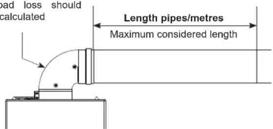
By referring to the length of pipes, choose and insert the correct flange: see the different diameters included in the packaging (see tab. on following page)

natural_image
Technical line drawing of a mechanical assembly with a bearing and housing (no text or symbols)Maximum pipe length (see following table)
The 90° appliance output curve load loss should NOT be calculated
| Exhaust type | Length pipes/metres Excluding the 90° appliance output curve | Fume flange (mm) The fume flange, when necessary, must be removed using a screwdriver as a lever | Load loss for each additional curve | |||
| 14Fi AM Blue | 17Fi AM Blue | 14Fi AM Blue | 17Fi AM Blue | 45° 90° | ||
| TIPO B22 - B22P Open chamber and forced draught for indoor | up to 7 | up to 4 | ø 45 | ø 46 | 1,3 m | 1,8 m |
| from 7 to 13 | from 4 to 8 | ø 47 | ø 48 | |||
| from 13 to 25 | from 8 to 12 | not installed | not installed | |||
| TIPO C - TIPO B32 Horizontal coaxial exhausts | up to 1 | up to 1 | ø 45 | ø 46 | 1 m | 1,4 m |
| from 1 to 1,9 | from 1 to 1,6 | ø 47 | ø 48 | |||
| from 1,9 to 3,7 | from 1,6 to 3,2 | not installed | not installed | |||
| TIPO C Vertical coaxial exhausts | up to 2 | up to 2 | ø 45 | ø 46 | 1 m | 1,4 m |
| from 2 to 2,9 | from 2 to 2,6 | ø 47 | ø 48 | |||
| from 2,9 to 4,7 | from 2,6 to 4,2 | not installed | not installed | |||
| TIPO C Split exhausts | 5+5 | 3+3 | ø 45 | ø 46 | 1,3 m | 1,8 m |
| from 5+5 to 9,5+9,5 | from 3+3 to 6+6 | ø 47 | ø 48 | |||
| from 9,5+9,5 to 17+17 | from 6+6 to 9+9 | not installed | not installed | |||
In the case of pipes with different lengths, see the graphs in fig. 8 pag. 58.
Warnings before ignition
Please remember that appliance installation, first ignition, maintenance and repairs must be performed by qualified personnel.
Before turning on the appliance, proceed with suitable checks:
- Ensure the gas system seal is good (according to current regulations)
- Make sure mains data match those stated on the data plate
- Make sure the installation meets current local regulations
- Check the type of gas set for appliance operations on the serial plate
- Make sure the flue meets current regulations
- Make sure the system pipes are free of residue, slag or dirt
- Check connections with the electrical mains, L-N polarity and grounding connections
- Check the mains pressure as indicated in the next paragraph.
Checking the system pressure (minimum supply pressure) (only for gas natural water heater)
- Unplug the water heater
- Removing the casing by unscrewing the fastening screws located on the bottom of the water heater and detaching the casing from the upper part (fig. 22 pag. 62)
- Remove the cover that closes the service inlet (located on the shelf) and insert through the hole the silicon pressure gauge tube
- Loosen by approximately two turns the screw of the pressure tap upstream of the gas valve and connect the pressure gauge to it (fig. 11 pag. 61)
- Carefully close the casing
- Use to increase the water temperature at the maximum value, the symbol flashing for 5 seconds and the display shows the new temperature
- Electrically connect the water heater
- Open a hot water valve to full capacity
Check the gas pressure referring to the values indicated in the data table. If the pressure is higher than 15 mbar, calibrate the gas valve.
During measurement a tolerance of +/-0.5 mbar is permitted.
- Close the hot water tap
- Disconnect the pressure gauge and tighten the pressure tap upstream of the gas valve.
During measurement a tolerance of +/-0.5 mbar is permitted. - Close the hot water tap - Disconnect the pressure gauge and tighten the pressure tap upstream of the gas valve.
Gas conversion
The gas conversion can be easily performed even while it is mounted.
The instructions for transforming and regulating the product to receive various types of gas are below.
This operation must be performed by qualified personnel according to law in force.
Disconnect the omni-polar switch outside the water heater and close the gas and water valves to the appliance.
- Remove the casing by referring to the specific paragraph
- For LPG conversion: place the plate on the collector as shown in fig. 12 pag. 61
- Remove the clip (detail E fig. 13 pag. 61)
- Disconnect and remove the gas pipe (detail F fig. 13 pag. 61)
- Turn the screws showed in fig. 14 pag. 61 and lower the plate
- Turn the collector fixing screws
- Extract the gas collector (fig. 15 pag. 61) and replace it
- Reposition the components that had previously been removed
Change parameters 02 and 13 (Gas type)
To select the type of gas it is necessary to set parameters 02 and 13
Start-up the appliance and access in the Parameters menu :
- With water heater powered on, hold down at the same time the buttons and for about 5 seconds, the display shows the symbol ☐☐
- Release the buttons
- Enter the code and confirm by pressing the button Having entered the "SERVICE MENU" it is possible to select the Relevant submenu:
- (Parameters menu)
- 02 (Parameters 02: Selection gas Natural gas/LPG)
- Associated parameters 02
If the code is incorrect or if the time set for the operation expires, the appliance automatically returns to the stand/by or operating status.
- Press ⏻: the value of parameter 02 flashing, press + and — to select the gas: 0 (NG) - 1 (LPG)
- Confirm by pressing ⏻
- Scroll +e — and select parameter 13
- Press ⏻: the value of parameter 13 flashing press + and — to select the gas, refer to the table below:
| PARAMETER 02 | PARAMETRO 13 | |
| NATURAL GAS (G20) 0 0 | ||
| BUTAN (G30) 1 2 | ||
| PROPAN (G31) 1 1 |
- Confirm by pressing ⏻
At the end of the procedure, the appliance displays alarm AL62 which indicates that the gas valve requires calibration.

Exit from the menu automatically stops after 5 minutes of inactivity or by pressing and holding the R button until the display shows MENU' flashing, release the button: the display shows the set temperature value.
Calibration gas valve
Before calibration check the mains pressure: 20 mbar for Natural gas - 37 mbar for LPG.

After each replacement of the electronic board or gas valve, set the appliance (complete electronic calibration b.R

The calibration of gas valve cancels the values (min/max) set at the factory.

The view, by means of a pressure gauge connected to the gas valve, of the pressure values (min/max) set at the factory, is carried out through the Manual Calibration (see chapter Service Menu).
- Place the electric switch of the system to off and remove the casing
- Remove the cover that closes the service inlet (located on the shelf - fig. 11 pag. 61) and insert through the hole the silicon pressure gauge tube
- Loosen by approximately two turns the screw of the pressure tap downstream (P-OUT) of the gas valve and connect the pressure gauge to it (fig. 11 pag. 61)
- Carefully close the casing and place the electric switch of the system to on
- Press the ⏻ and — keys until the display shows Ma followed by nu to form the word Manu (fig. 20 pag. 61)
- Press the key + until the display shows Au followed by to form the word Auto (fig. 20 pag. 61)
- Open the hot water tap at maximum
- The display shows P01 indicating that the appliance is operating at maximum capacity
- Scroll with + and - keys until the maximum pressure value of the burner is shown on the pressure gauge (ref. technical data)
- To store the value press the button ⏻
- Press the button ⏻ to select the next lowest setting value P00
- Scroll with + and - keys until the minimum pressure value of the burner is shown on the pressure gauge (ref. technical data)
- Press ⏻ to save the value
- Press Reset until Manu flashes. Release the key and the set temperature value is shown on the display
- Close the hot water tap

The calibration operation ends automatically after 15 minutes of inactivity or in the case of overtemperature (67°C).

In case of power loss it is necessary to repeat the procedure.
USE OF THE APPLIANCE

CONTROL PANEL fig. 29 pag. 63
Preliminary checks
Check that:
- The data of the power supply networks corresponds to that stated on the data plate
- The data plate information corresponds to that of the power supply networks (electric, water, gas)
- The installation complies with the local regulations in force
- The electrical connection to the mains and of the earthing connection have been performed correctly.
Appliance start-up
Following the necessary checks, proceed with the following operations:
Electrically power the water heater
Open the gas valve installed upstream of the water heater
Open the water tap at the bottom of the water heater
- Press the power button ⏻
- The display shows:
-
Software review
-
The type of gas for which the water heater was designed:
nG (G20) - bu (G30) - Pr (G31)
-
LE Low Emission product
-
Model
-
Symbols test (display ON)
With the first ignition procedure completed, the display shows the symbols — — (fig. 16 pag. 61).
Press the button ⏻ to power the water heater, the display shows the set point temperature, the symbol ⚡ (in case hot water request in progress) and the symbol ⚙ (in case of burner ON) (fig. 17 pag. 61).
Water temperature adjustment
The water temperature can be set between 37 and 60°C.
- Use + and — to increase and decrease the water temperature, the symbol flashing for 5 seconds and the display shows the new temperature.

Contact with hot water at a temperature ≥50^ C can cause severe burns.

For daily use of the appliance it is recommended to set the temperature at a value not exceeding 50°C.


The appliance is set to maintain a constant water temperature. It could happen that in the case of withdrawals at extremely low flow rates, the water temperature rises above the set value, causing burns. It is advisable to check always the water temperature before any use.
Set point regulation
To reduce gas consumption and prevent limescale in the heat exchanger, it is recommended to set the appliance at the minimum temperature most suitable for the domestic use.
Recommended temperature setting:
| Kitchen | 50°C - 55°C | Bathroom | 37°C - 45°C |
A cause of the system and environmental conditions could be a discrepancy between the temperature set on the appliance and that actually supplied to the user.
Switching off the appliance
- Hold down for about 5 seconds the water heater power off button
- As soon as the symbols start flashing, release the button
- The appliance will be in the OFF state and the display shows the symbols (fig. 16 pag. 61).
From this point forward the appliance remains inactive.

In the event that there is a possibility that the temperature in the room could drop below 3^ C, empty the water heater of the water by closing the cold water inlet valve and opening the hot water tap below the water supply network of the room.

In case of power off for lengthy periods, disconnect the omni-polar switch outside the water heater and close the gas valve upstream of the water heater.
To power the appliance, press for about 5 seconds the power button (!)
SERVICE MENU
Having entered the "SERVICE MENU" it is possible to select the relevant submenu:
- PARAMETERS MENU
- CALIBRATION MENU MANU
- ALARM HYSTORICAL MENU
- INFO MENU
Parameters menu 15
Having entered the "PARAMETERS MENU" the operating parameters of the appliance can be modified.
- Start-up the appliance, press and hold at the same time the buttons — and Reset for 5 seconds, the symbols □□ start flashing
- Release the button
- Hold down + and select code 06, confirm by pressing ⏻.
If the code is incorrect or the time set for the operation should expire, the appliance automatically returns to the standby or operating state.
- The display shows:
- 5 (parameters menu activated) (fig. 19 pag. 61)
- 02 (parameter 02: gas selection NG/LPG)
- Value of parameter 02
- Press + and - to show subsequent parameters
- Select the parameter and press ⏻: the value flashing, use + and — to change the value
- Confirm by pressing ⏻

Exit from the menu automatically stops after 5 minutes of inactivity or by pressing and holding the Reset button until the display shows MENU' flashing, release the button: the display shows the set temperature value.
Below is a list of editable parameters:
| no. | description | range | default |
| 02 | Gas type0 = Natural Gas1 = LPG | 0 - 1 | depending on the model |
| 08 | DHW off mode;0 = fixed1 = associated to DHW setpoint | 0 - 1 | 0 |
| 09 | Ignition power | 0 ... 40 | 40 |
| 10 | Ignition curve | 0 - 3 | 1 |
| 13 | Gas type0 = natural gas (G20)1 = propan (G31)2 = butan (G30)3 = not applicable | 0 - 3 | depending on the model |
| 18 | Domestic hot water modulation with flow meter0 = modulation without flow meter1 = modulation with flow meter | 0 - 1 | 1 |
| 26 | Water heater flow rate10 = 14Fi AM Blue11 = 17Fi AM Blue12 = not applicable13 = not applicable | 10 - 13 | depending on the model |
| 27 | Modulator reactivity | 0 - 1 | 0 |
| 28 | 0 = standard water heater from 1 to 20 = solar water heater, delay (in seconds) of ignition power if requested | 0 from 1 to 20 | 0 |

Any other additional parameters with respect to the table above should not be changed for any reason
Calibration menu MANU


Pressure adjustments must be carried out by a qualified technician

The following operations must be performed in sequence
Before calibration check the mains pressure.
To calibrate the gas valve (standard procedure MANU: partial calibration +/- 1,5 mbar):
- Place the electric switch of the system to off
- Remove the casing by unscrewing the fastening screws located at the bottom of the water heater and detached the casing from the top
- Remove the cover that closes the service inlet (located on the shelf - fig. 11 pag. 61) and insert through the hole the silicon pressure gauge tube
- Loosen by approximately two turns the screw of the pressure tap downstream of the gas valve and connect the pressure gauge to it
- Carefully close the casing and place the electric switch of the system to on
- Press and hold at the same time the buttons ⏻ and — the display shows first the word Ma and then the word to to compose Manu (fig. 20 pag. 61)
- Open the hot water tap until the burner start
- The display shows PO I (indicating that the water heater is operating at maximum capacity)
-
Use + and — until visualize on the pressure gauge the maximum burner pressure (see data table)
-
Confirm by pressing ⏻
- Press Ⓤ to select the next lowest setting value P00
- Use + and — until visualize on the pressure gauge the minimum burner pressure (see data table)
- Confirm by pressing ⏻
- Press Re until the display shows MENU' flashing, release the button: the display shows the set point temperature
- Close the hot water tap.

The calibration operation ends automatically after 15 minutes of inactivity or in the case of overheating (67°C) or by pressing and holding the Reset button until the display shows MENU' flashing, release the button: the display shows the set temperature value.
Alarm hystorical menu RL (fig. 18 pag. 61)
this feature allows displaying of the last 10 errors that have occurred on the appliance.
- Press and hold at the same time the buttons + and -
- The display shows the index of the last stored error and the word RL (example: 01 => RL)
- Use + and — to scroll through the errors index, display ranges from the most recent to the earliest.
If the user pauses, the display shows the letters AL to indicate access within the errors history menu.

The calibration operation ends automatically after 15 minutes of inactivity or pressing Reset button until the display shows MENU' flashing, release the button: the display shows the set temperature value.
Info menu in (fig. 21 pag. 61)
this feature allows displaying:
- Last version of software review
- Hot water temperature in direct
- Hot water quantity in direct (l/min)
To activate the Menu:
- Press and hold at the same time the buttons + and Reset
- To shows the info, scroll with the buttons +e -
This menu is active during all the production of instant hot water.

The calibration operation ends automatically after 15 minutes of inactivity or pressing Reset button until the display shows MENU' flashing, release the button: the display shows the set temperature value.
ANOMALIES AND DISPLAY VIEWS
Should the appliance shut down the display shows the letters AL (fig. 18 pag. 61) followed by an fault code which should be consulted in relation to the shutdown.
Two types of shutdown are possible:
- Temporary shutdown (non-permanent). The fault code flashes, shutdown is automatically removed upon resolution of the problem that caused it. If the fault persists, shutdown switches from temporary to permanent
- Permanent shutdown (lock), the fault code is steady. In this case the appliance does not start again automatically and must only be released by the user or by the operator via the release procedure.
Below are listed the types of alarms, their typical display views and the solutions to reset the appliance:
| Display Alarm | type Solutions | |
| Permanent shutdown | Flame control module shutdown alarmFlame control electronic fault alarm | Press and hold the button. As soon as the letters appear on the display, release the button.The appliance automatically restarts. If the fault persists, request the assistance of a qualified technician. |
| Permanent shutdown | Limit thermostat alarm | Press and hold the button. As soon as the letters appear on the display, release the button.The appliance automatically restarts. If the fault persists, request the assistance of a qualified technician. |
| Permanent shutdown | Domestic water NTC fault alarm IN-OUT | Request the assistance of a qualified technician. |
| Temporary shutdown | Parasitic flame alarm Request the assistance of a qualified technician. | |
| Permanent shutdown | Interrupted modulator cable alarm | Press and hold the button. As soon as the letters appear on the display, release the button.The appliance automatically restarts. If the fault persists, request the assistance of a qualified technician. |
| Permanent shutdown | Alarm in case of 5 consecutive resets | To reset the appliance, disconnect and reconnect the electrical voltage.Press and hold the button. As soon as the letters appear on the display, release the button.If the fault persists, request the assistance of a qualified technician. |
 Temporary shutdown Temporary shutdown | Low Voltage Alarm Wait until automatic reset of the water heater. If the fault persists, request the assistance of a qualified technician. | |
 Temporary shutdown Temporary shutdown | Incorrect mains frequency detection alarm | Wait until automatic reset of the water heater. If the fault persists, request the assistance of a qualified technician. |
 Permanent shutdown Permanent shutdown | Flame loss for more than 3 consecutive times alarm | Request the assistance of a qualified technician. |
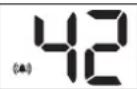 Temporary shutdown Temporary shutdown | Button alarm This is displayed when you keep pressed the button for more than 30 seconds, once the button is released the fault disappears. | |
 Permanent shutdown Permanent shutdown | Remote control panel communication fault (only for external model) | Request the assistance of a qualified technician. |
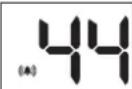 Permanent shutdown Permanent shutdown | Alarm for Time out gas valve | Press and hold the R button. As soon as the letters appear on the display, release the button. The appliance automatically restarts. If the fault persists, request the assistance of a qualified technician. |
 Permanent shutdown Permanent shutdown | Valve calibration request Request the assistance of a qualified technician. | |
 Temporary shutdown Temporary shutdown | AL70 - Inlet temperature >70°C alarm A single flashing bell is displayed The full display is only available in the alarm log | Request the assistance of a qualified technician. |
 Permanent shutdown Permanent shutdown | Alarm as domestic water Delta T not reached upon power on | Request the assistance of a qualified technician. |
 Permanent shutdown Permanent shutdown | Driver error alarm (software not updated) | Request the assistance of a qualified technician. |
 Permanent shutdown Permanent shutdown | Alarm for combustion problem upon power on | Press and hold the R button. As soon as the letters appear on the display, release the button. The appliance automatically restarts. If the fault persists, request the assistance of a qualified technician. |
 Permanent shutdown Permanent shutdown | Shutdown due to persistent poor combustion | Request the assistance of a qualified technician. |
 Temporary shutdown Temporary shutdown | Alarm due to poor combustion Request the assistance of a qualified technician. | |
 Temporary shutdown Temporary shutdown | AL84 - Poor combustion alarm A single flashing flame is displayed The full display is only available in the alarm log | Request the assistance of a qualified technician. |
 Permanent shutdown Permanent shutdown | Alarm sensor fan speed Request the assistance of a qualified technician. |
 Display Display | High temperatures Request the assistance of a qualified technician. |
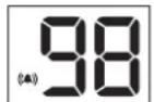 Permanent shutdown Permanent shutdown | Software fault alarm, electronic board start-upRequest the assistance of a qualified technician. |
MAINTENANCE

Qualified personnel should inspect the appliance following the law in force, this is to ensure correct, continuous and reliable operation of the water heater.

Insufficient or inadequate maintenance can compromise the safety of the appliance.

Before carrying out any cleaning or maintenance, switch off the appliance using the omni-polar switch on the power supply line and close the gas and water valves to the appliance.
External cleaning
A periodic cleaning of the external panels as well as improving the appearance, it preserves the corrosion paneling, extending its life.
To clean the exterior panels use a cloth dampened with soapy water.
Do not use solvents, powders or abrasive sponges.
Do not clean the appliance and/or its parts with flammable substances (example: petrol, alcohol, oil, etc.).
Dismantling the casing (fig. 22 pag. 62)
Remove the casing by unscrewing the fastening screws located on the bottom of the water heater and detaching the casing at the top.
Accessibility to the electronic board (fig. 23 pag. 62)
Remove the casing by referring to the specific paragraph.
Remove the panel by unscrewing the screws that secure it to the seat of the electronic board.
Disconnect the connectors.
Removing the gas valve (fig. 24 pag. 62)
Remove the casing by referring to the specific paragraph.
Unscrew the screws that secure the panel to the bottom shelf.
Remove the panel without disconnecting the wiring and attach it to the bracket as shown in the figure.
Disconnect the gas valve by unscrewing the retaining screws and the nuts connecting to the gas pipe.
Removing the fan (fig. 25 pag. 62)
Remove the casing by referring to the specific paragraph.
Unscrew the fixing screws of the fan.
Lower the fan freeing it from the hooks and slide it to the left.
Removing the burner (fig. 26 pag. 62)
Remove the casing by referring to the specific paragraph.
Disconnect the clip (detail E fig. 13 pag. 61).
Disconnect and remove the gas pipes (detail F fig. 13 pag. 61).
Turn the screws showed in fig. 14 pag. 61 and lower the plate.
Referring to fig. 26 pag. 62: unscrew the nut, remove the clip and extract the hot water outlet pipe.
Turn the fixing screws in fig. 27 pag. 62 and remove the burner.
Dismantling the heat exchanger (fig. 28 pag. 62)
Remove the casing and the burner by referring to the specific paragraph.
Disconnect the cold water inlet pipe.
Remove the fixing screws of the heat exchanger and remove it.
TECHNICAL DATA
| 14Fi AM Blue 17Fi AM Blue | |||||||
| PIN Nr. 0476CS2173 | |||||||
| Nominal heat input (Qn) | kW-kcal/h 27,0 - 23.220 33,0 - 28.380 | ||||||
| Nominal output power (Pn) | kW-kcal/h 24,0 - 20.640 29,4 - 25.280 | ||||||
| Minimum heat input (Qm) | kW-kcal/h 4,5 - 3.870 5,6 - 4.820 | ||||||
| Minimum output power (Pm) | kW-kcal/h | 4,2 - 3.610 5,1 - 4.390 | |||||
| GAS TYPE | NATURAL GAS | LPG | NATURAL GAS | LPG | |||
| G20 G30 G31 G20 G30 G31 | |||||||
| P.C.I. (15°C 1013 mbar) | MJ/m3 | 34,02 116,09 88,0 34,02 | 116,09 | 88,0 | |||
| WI (15°C 1013 mbar) | MJ/m3 | 45,67 | 80,58 | 70,69 | 45,67 | 80,58 | 70,69 |
| Consumption (15°C 1013 mbar) | 2,86 m3/h | 2,13 kg/h | 2,10 kg/h | 3,49 m3/h | 2,60 kg/h | 2,56 kg/h | |
| Maximum burner pressure | mbar | 12,2 | 28,3 | 36,2 | 12,9 | 28,1 | 35,8 |
| Minimum burner pressure | mbar | 2,1 | 4,2 | 5,6 | 2,6 | 4,8 | 5,7 |
| Nr Nozzles /∅ Main burner nozzle | Nr/mm | 24 x 0,86+ 4 x 0,83 | 24 x 0,50+ 4 x 0,48 | 30 x 0,86+ 4 x 0,83 | 30 x 0,50+ 4 x 0,48 | ||
| NOx Emission (EN26:2015 on Hs) | mg/kWh | 40 | 61 | 36 | 44 | 56 | 35 |
| ∅ Gas connection | " | 3/4 | 3/4 | ||||
| Country of destination - Category - Nominal supply pressure (mbar) | IT - II2R3R - G20: 20 G30/G31: 28-30/37ES/PT - II2R3R - G20: 20 G31: 37ES/PT - I3R - G30: 28-30 G31: 37 | ||||||
| FUMES EXHAUSTION | 14Fi AM Blue 17Fi AM Blue | ||||||
| G20 G30 G31 G20 G30 G31 | |||||||
| Flue gas mass flow rate (max-min) | g/s | 20,943 - 11,285 | 20,394 - 11,459 | 19,058 - 10,247 | 21,504 - 14,044 | 20,043 - 11,673 | 20,491 - 11,094 |
| Flue temperature (max-min) | °C | 165 - 58 | 164 - 52 | 162 - 58 | 184 - 64 | 172 - 54 | 184 - 62 |
| Air capacity | Nm3/h | 58,163 | 56,620 | 52,737 | 59,622 | 55,544 | 56,617 |
| ∅ flue gas release tube | mm | 100/60 80/80 | 100/60 80/80 | ||||
| Nominal CO2 (tolerance ± 0,5) | % | 5,2 | 6,1 | 6,5 | 6,2 | 7,6 | 7,4 |
| FAN PERFORMANCE | 14Fi AM Blue | 17Fi AM Blue | |||||
| Residual head of boiler without pipes | Pa | 90 | 115 | ||||
| ELECTRICAL CIRCUIT | 14Fi AM Blue | 17Fi AM Blue | |||||
| Power supply voltage | V - Hz | 230 ~ - 50 | 230 ~ - 50 | ||||
| Electric power | W | 59 | 74 | ||||
| Degree of Protection | IPX5D | IPX5D | |||||
| INSTALLATION SITE TEMPERATURE | 14Fi AM Blue | 17Fi AM Blue | |||||
| Minimum working temperature | °C | 3 | 3 | ||||
| WATER | 14Fi AM Blue | 17Fi AM Blue | |||||
| Domestic water flow limiter | l/min | 12 | 12 | ||||
| Continuous intake capacity (ΔT 35 K) | l/min | 9,8 | 12 | ||||
| Minimum ignition flow | l/min | 2 | 2 | ||||
| Selectable water temperature | °C | 37 - 60 | 37 - 60 | ||||
| Minimum pressure | bar | 0,13 | 0,13 | ||||
| Maximum pressure | bar | 10 | 10 | ||||
| ∅ water connections | " | 1/2 | 1/2 | ||||
| DIMENSIONS AND WEIGHTS | 14Fi AM Blue | 17Fi AM Blue | |||||
| Height | mm | 617 | 617 | ||||
| Width | mm | 385 | 385 | ||||
| Depth | mm | 222 (228 with aesthetics) | 222 (228 with aesthetics) | ||||
| Weight | Kg | 15 | 17 | ||||
Note: cold water temperature of reference 15°C.
The data relating to domestic hot water performance refer to a dynamic inlet pressure of 2 bar and an inlet temperature of 15^ C; the values are detected immediately at the water healer outlet considering that mixing with cold water is necessary to obtain the declared data.
natural_image
Technical line drawing of a mechanical assembly with a central component and housing (no text or symbols)DESCRIÇÃO DOS SÍMBOLOS UTILIZADOS NO MANUAL E NA EMBALAGEM
natural_image
Technical line drawing of a mechanical assembly with a central component and mounting base (no text or symbols)natural_image
Two schematic diagrams of a fluid system with pipes and valves, showing internal flow patterns (no text or labels)B32
natural_image
Diagram of a fluid system with airflow and heat exchanger (no text or labels)C12 - C12X
C32 - C32X
natural_image
Diagram of two identical air purification or cooling systems with heat exchangers and airflow paths (no text or labels)C52 - C52X

IT EN ES PT


- DESCRIPTION OF THE SYMBOLS USED IN THE MANUAL AND ON THE PACKAGING
- WARNING
- ATTENTION
- QUICK-START GUIDE
- POWER ON
- WATER TEMPERATURE ADJUSTMENT
- POWER OFF
- RESET
- GENERAL WARNINGS AND SAFETY DEVICES
- To optimise use, be aware that:
- DESCRIPTION OF THE APPLIANCE
- INSTALLATION
- Regulations
- Wall mounting
- Precautions
- Location
- Support bracket (fig. 7 pag. 57)
- Electrical connection
- Gas connection
- Water connection
- Evacuation of combustion products (fig. 8-9-10 pag. 58-59)
- TYPE B22/B22P: Open chamber and forced draught for indoor use
- TYPE B32: Horizontal coaxial exhausts
- TYPE C: Horizontal coaxial exhausts
- TYPE C: Vertical coaxial exhausts
- TYPE C: Split exhausts
- Warnings before ignition
- Checking the system pressure (minimum supply pressure) (only for gas natural water heater)
- Gas conversion
- Change parameters 02 and 13 (Gas type)
- Calibration gas valve
- USE OF THE APPLIANCE
- Preliminary checks
- Appliance start-up
- Set point regulation
- Switching off the appliance
- SERVICE MENU
- Parameters menu 15
- Calibration menu MANU
- Alarm hystorical menu RL (fig. 18 pag. 61)
- Info menu in (fig. 21 pag. 61)
- ANOMALIES AND DISPLAY VIEWS
- MAINTENANCE
- External cleaning
- Dismantling the casing (fig. 22 pag. 62)
- Accessibility to the electronic board (fig. 23 pag. 62)
- Removing the gas valve (fig. 24 pag. 62)
- Removing the fan (fig. 25 pag. 62)
- Removing the burner (fig. 26 pag. 62)
- Dismantling the heat exchanger (fig. 28 pag. 62)
- DESCRIÇÃO DOS SÍMBOLOS UTILIZADOS NO MANUAL E NA EMBALAGEM
Brand : Baxi
Model : 11Fi Blue
Category : Heating