
VLF613 - TV Stand SANUS - Free user manual and instructions
Find the device manual for free VLF613 SANUS in PDF.


| Product Type | TV Stand |
| Brand | Sanus |
| Model | VLF613 |
| Material | Tempered glass and steel |
| Max TV Size | 42 inches |
| Max TV Weight | 50 lbs (22.7 kg) |
| Dimensions (W x D x H) | 32.5 x 16 x 20 inches |
| Shelf Count | 2 (including top) |
| Cable Management | Yes, with removable covers |
| Color | Black |
| Weight of Stand | 25 lbs (11.3 kg) |
| Assembly Required | Yes |
| VESA Compatibility | 100x100, 200x200 mm |
| TV Orientation | Landscape only |
| Anti-Tip Bracket | Included |
| Cleaning | Soft dry cloth |
| Warranty | Limited lifetime |
| Compatibility | Most flat-panel TVs |
| Included Hardware | Screws, spacers, level, manual |
| Maximum Shelf Load | 10 lbs per shelf |
Frequently Asked Questions - VLF613 SANUS
User questions about VLF613 SANUS
0 question about this device. Answer the ones you know or ask your own.
Ask a new question about this device
Download the instructions for your TV Stand in PDF format for free! Find your manual VLF613 - SANUS and take your electronic device back in hand. On this page are published all the documents necessary for the use of your device. VLF613 by SANUS.
USER MANUAL VLF613 SANUS
natural_image
Technical line drawing of a mechanical assembly with metal brackets and mounting holes (no text or symbols)VLF613
INSTRUCTION MANUAL
GET IT RIGHT
THE FIRST TIME
Follow this step-by-step instruction manual to speed up your installation.
WE'RE HERE TO HELP

Want to watch a video that shows how easy this DIY project will be?

Watch it now at: SANUS.com/2575
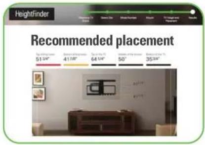
Get it right the first time. HeightFinder™ shows you where to drill.

Check it out at: SANUS.com/1172

natural_image
Group of employees in a modern office environment, one wearing a headset and the other seated at workstations (no visible text or signage)Our US-based install experts are standing by to help.

Call us at: 800-359-5520

Or, chat at: SANUS.com/chatSP
IMPORTANT SAFETY INSTRUCTIONS – SAVE THESE INSTRUCTIONS – PLEASE READ ENTIRE MANUAL PRIOR TO USE
Before getting started, let's make sure this mount is perfect for you!
Does your TV (including accessories) weigh MORE than 125 lbs. (56.6 kg)?

No — Perfect!
Yes — This mount is NOT compatible. Visit MountFinder.Sanus.com or call 1-800-359-5520 (UK: 0800-056-2853) to find a compatible mount.
2
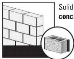
What is your wall made of?



Call Customer Service: 1-800-359-5520 (UK: 0800-056-2853)
3
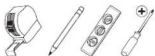
Do you have all the tools needed?


4
Ready to begin?
Please read through these instructions completely to be sure you're comfortable with this easy install process. Also check your TV owner's manual to see if there are any special requirements for mounting your TV.
If you do not understand these instructions or have doubts about the safety of the installation, assembly or use of this product, contact Customer Service at 1-800-359-5520 (UK: 0800-056-2853).

CAUTION: Avoid potential personal injuries and property damage!
● This product is designed for use in wood stud, solid concrete, and concrete block walls - DO NOT install into drywall alone
- The wall must be capable of supporting five times the weight of the TV and mount combined
- Do not use this product for any purpose not explicitly specified by manufacturer
• Manufacturer is not responsible for damage or injury caused by incorrect assembly or use
Before you begin
Don't stress out when you see all the hardware included.
Extra TV screw sizes and lengths are provided to fit most TVs.
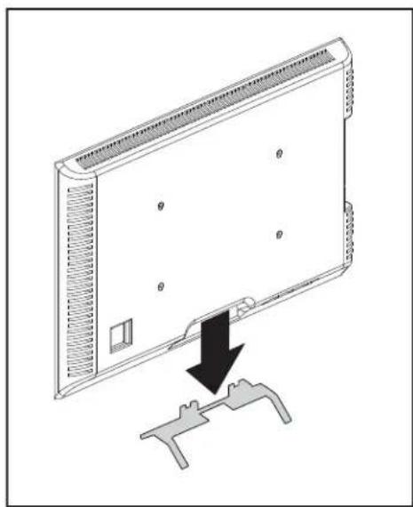
Remove the stand from your TV — if attached.
Install any accessories
you may have purchased — if they require the TV to be removed from the wall for assembly. The TV is removable for future accessory purchases.

natural_image
Diagram of a server rack with a black arrow indicating a drop or compression action (no text or symbols present)
natural_image
Diagram showing a device with a lid and a support bracket, no text or symbols presentStep-by-Step illustrations
speed up your installation.
Don't get it? Read the detailed explanation below each step.
Read ALL CAUTION warnings.
These are IMPORTANT!
Protect the face of your TV when laying it down for installation.
1 ASSEMBLE


TIP:
Each component has a number designation. See PAGE 6.
Secure part X to housing Y using screw S.
CAUTION: Avoid potential
Read Important Stuff read read rea Must Read read read read read rea Read read read Safety First read re
IMPORTANT: Read Important read
NOTE: Read read Dually Noted read
TIP: Read That's Helpful read read

Let's Go

Attach TV Bracket to TVSTEP 1
WARNING: This product contains small items that could be a choking hazard if swallowed. Before starting assembly, verify all parts are included and undamaged. If any parts are missing or damaged, do not return the damaged item to your dealer; contact Customer Service. Never use damaged parts!

NOTE: Not all hardware included will be used.
Parts and Hardware for STEP 1

1.1 Select TV Screws


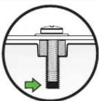
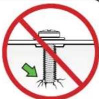
Too Short Correct Too Long
CAUTION:
Verify adequate thread engagement with your
screw/washer/spacer combination AND the TV bracket. (STEP 1.2).
TOO SHORT will not hold the TV and TOO LONG will damage the TV.
Determine which screw diameter (M6 or M8) fits the four mounting holes on the back of your TV.
1.2 Spacer Determination


For flat-back TVs, no
spacers 11 12
or 13 are required.
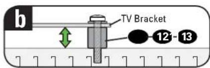

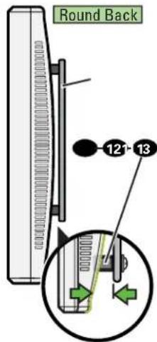
For rounded-back TVs, cable interference or inset holes, spacers 11, 12 or 13 to create extra space between the TV and TV bracket.

If your TV included inset spacers or wall mount oters, see Troubleshooting on PAGE 27.

1.3 Assemble TV Bracket

Loosen the two lower fasteners enough to slide the outer columns on TV bracket 01 (Indicated with arrows).
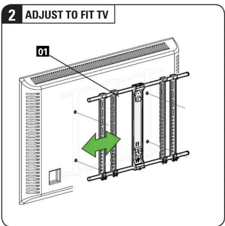
Adjust TV bracket 01 to line up with your TV's mounting hole pattern.

Be sure the center column is evenly spaced between the outer columns.
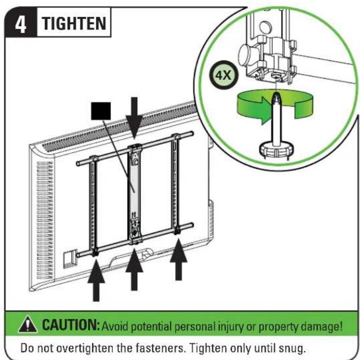
Tighten the two lower fasteners, and verify the two middle lower/upper fasteners are tightened. (Indicated with arrows).
1.4 Attach TV Bracket Assembly to TV

Center the TV bracket 01 over your TV hole pattern as shown, making sure the bracket is level. Note the orientation of the bracket.

Install using the spacer, screw and washer combination you selected for your TV.
STEP 2
Attach Wall Plate to Wall

WARNING:
This product contains small items that could be a choking hazard if swallowed. Before starting assembly, verify all parts are
included and undamaged. If any parts are missing or damaged, do not return the damaged item to your dealer; contact Customer Service.
Never use damaged parts!

NOTE:
Not all hardware included will be used.
Parts and Hardware for STEP 2
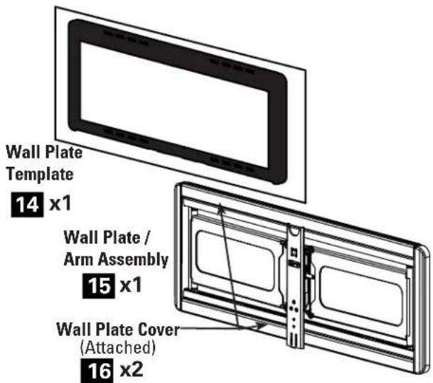
For concrete installations ONLY

CAUTION: Do not use in drywall or wood
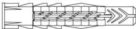
Concrete Anchor

natural_image
Pure mechanical component diagram without any text, numbers, or symbolsFischer UX10 x 60R
STEP 2A

Stud Installation
CAUTION: Avoid potential personal injury or property damage!
- Drywall covering the wall must not exceed 5/8 in. (1.5 cm)
- Minimum wood stud size: nominal 2 x 4 in. (5.1 x 10.2 cm) actual 1 ½ x 3 ½ in. (3.8 x 8.9 cm)
• Minimum horizontal space between fasteners:16 in. (40.6 cm)
• Stud centers must be verified

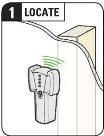
Locate the studs using a stud finder.
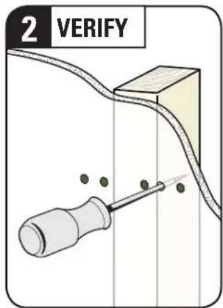
Find the edges of the studs using an awl or small drill bit.

Mark the centers of the studs with a pencil.
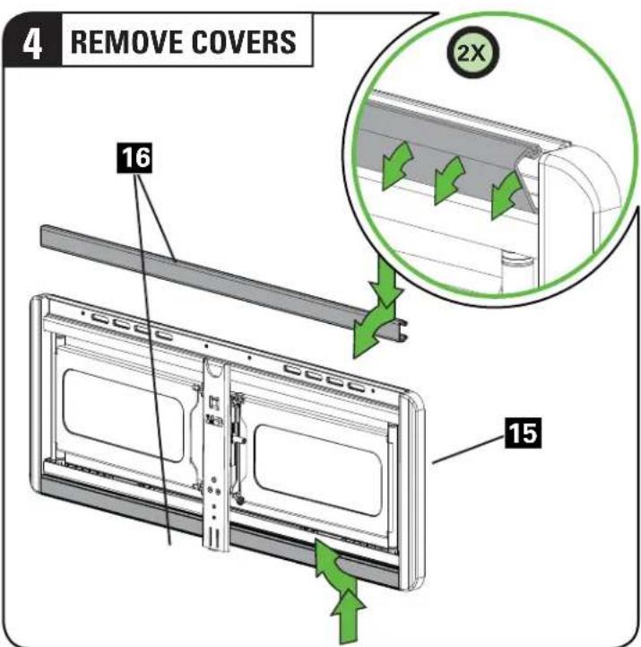
Remove wall plate covers 16 by pushing the outer edge inward, while pulling the cover forward.
![5 POSITION TEMPLATE Visit HeightFinder™ sanus.com /1172 14 TIP: To calculate your precise wall plate location, check out our HeightFinder at sanus.com [www.sanus.com/1172].](/content/2026/05/980035/images/09c261209fa086f166d9292bd1fe211ac3f96211d87887890fa8343507d474a4.jpg)
Place the wall plate template 14 at your desired height and position the slotted holes over your stud center lines. Level and tape in place.
STEP 2A tinued)
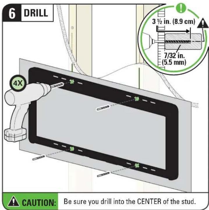
Drill the four pilot holes using a 7/32 in. (5.5 mm) diameter drill bit.
IMPORTANT: Pilot holes must be drilled to a depth of 3½ in. (8.9 cm).
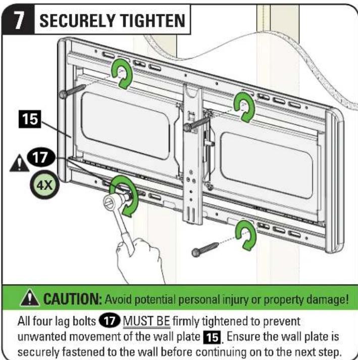
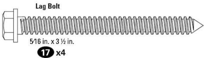
Install the four lag bolts 17 and firmly tighten until they are pulled flush against the wall plate/arm assembly 15.
Go to STEP 3 on PAGE 18.
STEP 2B
Solid Concrete or Concrete Block Installation
CAUTION: Avoid potential personal injury or property damage!
- Mount the wall plat 15 directly onto the concrete surface
• Minimum solid concrete thickness: 8 in. (20.3 cm)
• Minimum concrete block size: 8 x 8 x 16 in. (20.3 x 20.3 x 40.6 cm)
• Minimum horizontal space between fasteners: 24 in. (61.0 cm) - For Concrete applications, the arm assembly of wall plate/arm assembly 15 must remain centered in the wall plate. Keep this in mind when selecting the wall plate location.
1 REMOVE COVERS

Remove wall plate covers 16 by pushing the outer edge inward, while pulling the cover forward.
STEP 2B
tinued)
![2 POSITION TEMPLATE Visit HeightFinder™ sanus.com /1172 4X 14 Min. 24 in. (61.0 cm) TIP: To calculate your precise wall plate location, check out our HeightFinder at sanus.com [www.sanus.com/1172]](/content/2026/05/980035/images/b240619e982bfb3ccfa4a63d3b213a7fea3ff1482af009f39708ca2dcfe853be.jpg)
Position the wall plate template 14 on the wall at your desired height. Level and tape in place.

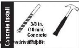
Drill four pilot holes using a 3/8 in. (10 mm) diameter drill bit.
IMPORTANT: Pilot holes must be drilled to a depth of 3 34 in. (9.5 cm).

Insert four anchors 18.
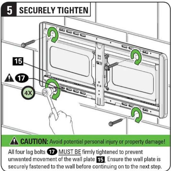
Install the four lag bolts 17. Firmly tighten all four lag bolts 17 until they are pulled flush against the wall plate/arm assembly 15.
STEP 3
Attach TV to Wall Plate
WARNING:
Before starting assembly, verify this part is undamaged. If damaged, do not return the damaged item to your dealer; contact
Customer Service. Never use damaged parts!
Parts and Hardware for STEP 3
3.1 Hang Your TV

Hang the TV/Bracket assembly 01 onto wall plate/arm assembly 15
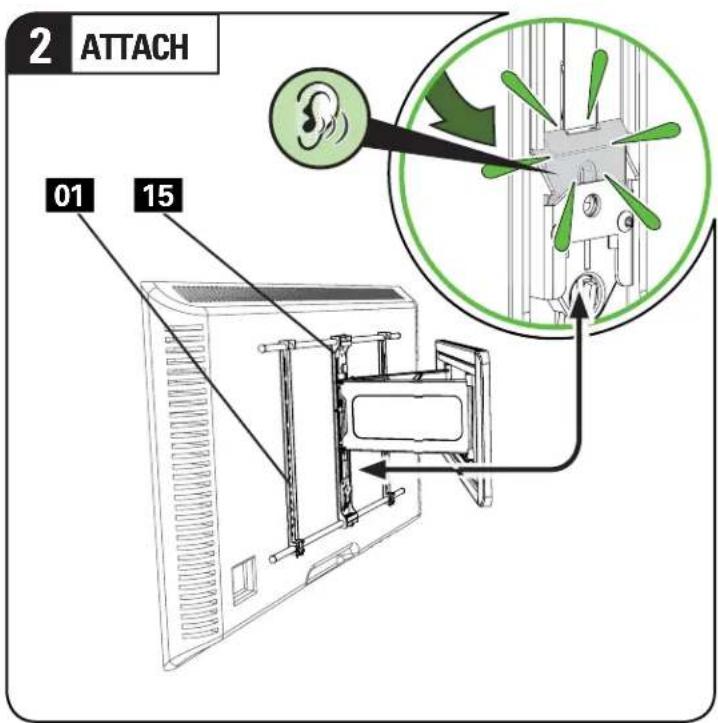
Press the bottom of the TV into the wall plate/arm assembly 15 until you hear the lock click, securing the TV in place.
3.1 (continued)
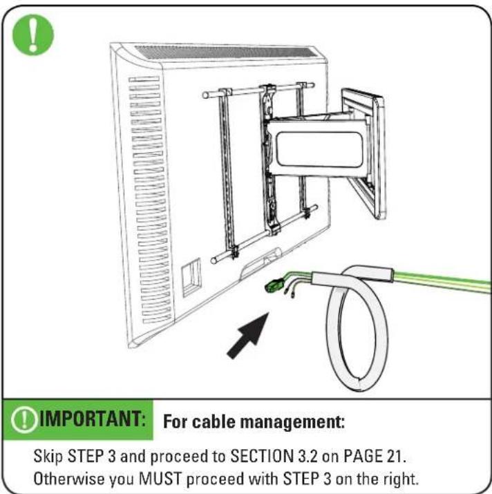
To secure your cables using the cable system, go to PAGE 21 now. If skipping the cable system, you MUST complete STEP 3 on the right.

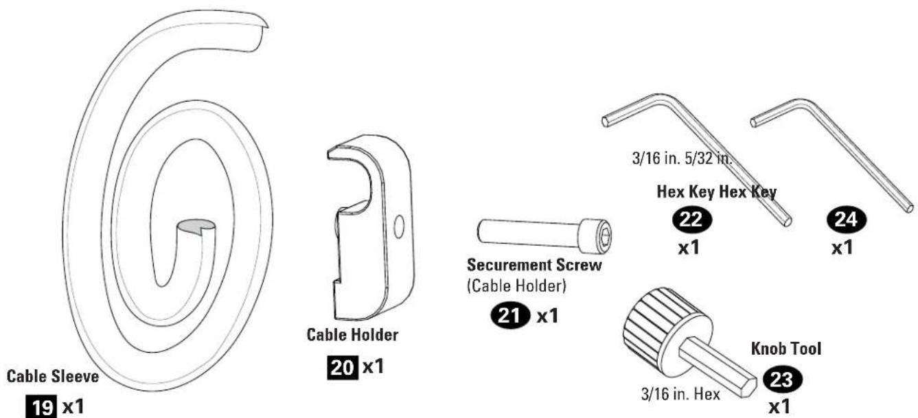
To lock the TV in place on wall plate/arm assembly 15, install the cable holder 20 and securement screw 21 as shown.
3.2 Manage Cables
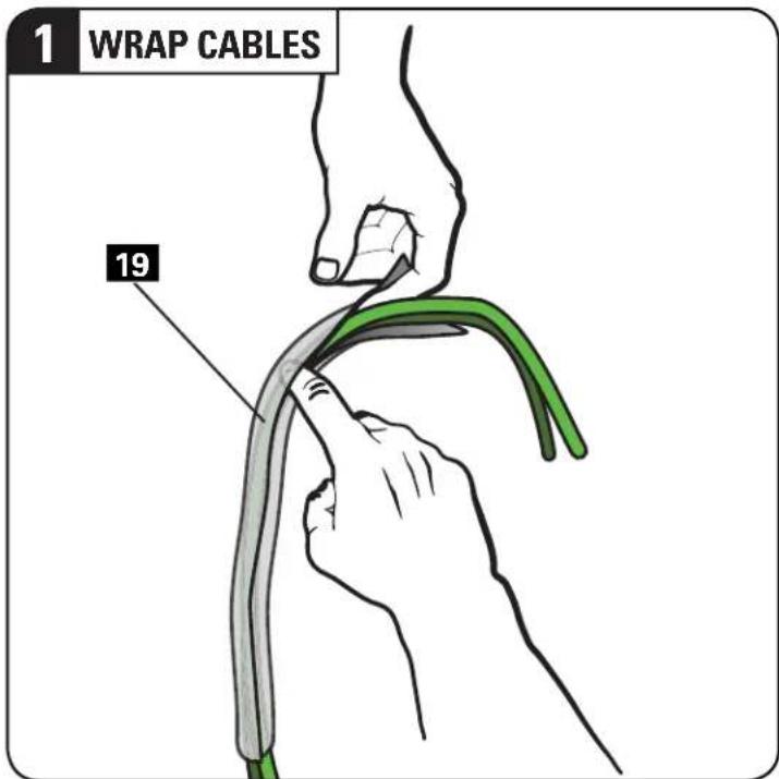
Slip your cables into cable sleeve 19.
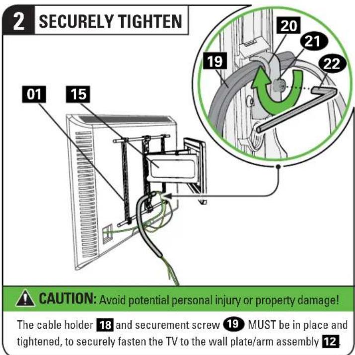
Secure the cables and cable sleeve 19, with the cable holder 20 and securement screw 21 as shown.
3.2 (continued)
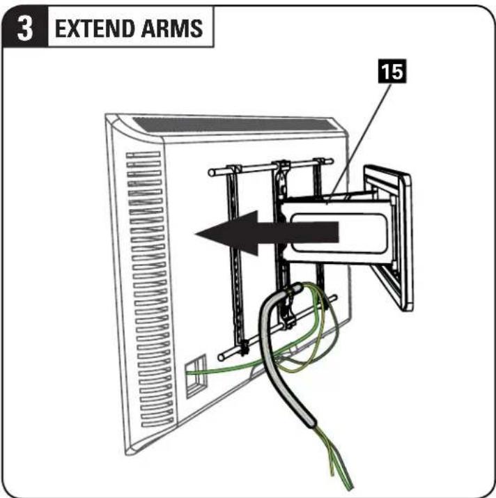
Pull the arms of wall plate/arm assembly 15 to full extension, to leave enough slack and prevent stretching the cables when the TV is moved.

Insert the free end of cable sleeve 19 into the channels of wall plate/arm assembly 15.
3.3 Install Cover Strips

Secure the cables onto the bottom channel of wall plate/arm assembly 15, by snapping in the bottom wall plate cover 16

Install the top wall plate cover 16.
Adjustments

LEVEL
Loosen leveling screw Ⓛ.
Level your TV, then tighten leveling screw Ⓛ.

TILT
Your TV should adjust easily when moved, then stay in place.
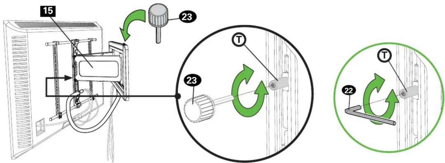
Adjust the tilt tension knob Ⓣ using knob tool 23 if your TV naturally tilts up or down.
NOTE: If you do not intend to adjust the tilt for different viewing locations, you can tighten the tilt tension knob using knob tool 23 to prevent unwanted movement.
NOTE: If needed for additional tightening, you may also tighten the tilt tension knob using hex key 22.

REMOVING THE TV

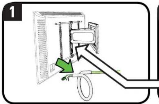
HEAVY! You may need assistance with this step.
- Disconnect all cables from the TV.
- Remove the cable holder 20 and securement screw 21.
- Pull down on the Release ring to release the TV.
- Carefully lift the TV from wall plate/arm assembly 15.


Troubleshooting
TV supplied spacers

a: Use your TV supplied spacer/adapter for flat back TVs (AND you want your TV closer to the wall).


CAUTION: Avoid potential injury or property damage!
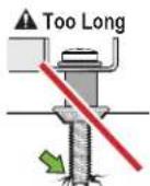
Use the correct screw length for adequate thread engagement.
- Too short will not hold the TV.
- Too long will damage the TV.
▲ Too Short

▲ Too Long
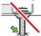
Correct

If you are uncertain about your hardware selection, contact Customer Service at 1-800-359-5520
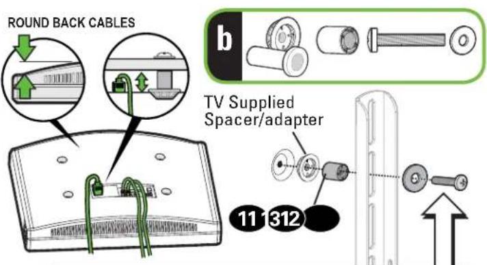
b: Use your TV supplied spacer/adapter and spacer 11, 12 or 13 for: • Round (irregular) back TVs • Extra space needed for cables

CAUTION: Avoid potential injury or property damage!
Use the correct screw length for adequate thread engagement.
- Too short will not hold the TV.
- Too long will damage the TV.


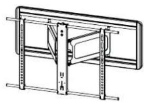
FULLY ASSEMBLED MOUNT
![1.88 [47.7] OFFSET](/content/2026/05/980035/images/e1d20ba0ffa01ba005534e00a8085b1456d4ef1fa36e97c9e64eb7404217e182.jpg)
TOP VIEW - EXTENDED
![13.5 [342] 25° 22° SIMULATED 50° FLAT SCREEN TV.](/content/2026/05/980035/images/479c339b6c5d92cd6d1cf5e6b1f9a9a4c6e3343d56c4c9aa807831e79cc6a9da.jpg)
TOP VIEW - RETRACTED
![1.86 [47.3]](/content/2026/05/980035/images/aa39194c0cb9914e85464c43d6dff61b7496dc6709837e03410806764bebda96.jpg)
3-D
natural_image
Technical line drawing of a mechanical assembly with no visible text or symbolsSIDE VIEW - TILT RANGE

SIDE VIEW - RETRACTED
Milestone AV Technologies and its affiliated corporations and subsidiaries (collectively, "Milestone"), intend to make this manual accurate and complete. However, Milestone makes no claim that the information contained herein covers all details, conditions, or variations. Nor does it provide for every possible contingency in connection with the installation or use of this product. The information contained in this document is subject to change without notice or obligation of any kind. Milestone makes no representation of warranty, expressed or implied, regarding the information contained herein. Milestone assumes no responsibility for accuracy, completeness or sufficiency of the information contained in this document.
ONE MORE THING: BE A WINNER!

Register your new mount and tell us how you like it for a chance to win in our monthly sweepstakes.
Entering is quick and easy. Visit SANUS.com/1234 and follow three simple steps for your chance to win.
"Monthly Prize" sweepstakes rules and restrictions apply. Visit SANUS.com/1234 for details.
natural_image
Woman standing beside a modern flat-screen TV in a room with curtains and windows (no visible text or symbols)When you share your handiwork with your friends, tag
sanusspaces
for a chance to be featured in the Inspiration Gallery on SANUS.com.

SANUS.com
WE MAKE IT EASY

SanusSystems
CHAT WITH US

pinterest.com/Sanus
BE INSPIRED

SanusSystems
WATCH AND LEARN
800-359-5520 • info@sanus.com • SANUS.com
SANUS • 6436 City West Parkway • Eden Prarie, MN 55344 USA
©2016 Milestone AV Technologies. All rights reserved. SANUS is a division of Milestone.
All other brand names or marks are used for identification purposes and are trademarks of their respective owners.
6901-602109 00


- VLF613
- GET IT RIGHT
- THE FIRST TIME
- WE'RE HERE TO HELP
- IMPORTANT SAFETY INSTRUCTIONS – SAVE THESE INSTRUCTIONS – PLEASE READ ENTIRE MANUAL PRIOR TO USE
- Before getting started, let's make sure this mount is perfect for you!
- 2
- 3
- 4
- Before you begin
- Step-by-Step illustrations
- Read ALL CAUTION warnings.
- Protect the face of your TV when laying it down for installation.
- CAUTION: Avoid potential
- Attach TV Bracket to TVSTEP 1
- Select TV Screws
- Spacer Determination
- Assemble TV Bracket
- Attach TV Bracket Assembly to TV
- STEP 2
- Attach Wall Plate to Wall
- WARNING:
- NOTE:
- STEP 2A
- Stud Installation
- CAUTION: Avoid potential personal injury or property damage!
- STEP 2A tinued)
- STEP 2B
- Solid Concrete or Concrete Block Installation
- tinued)
- STEP 3
- Attach TV to Wall Plate
- Hang Your TV
- (continued)
- Manage Cables
- (continued)
- Install Cover Strips
- Adjustments
- LEVEL
- TILT
- REMOVING THE TV
- Troubleshooting
- TV supplied spacers
- ONE MORE THING: BE A WINNER!
- sanusspaces
Brand : SANUS
Model : VLF613
Category : TV Stand