
CFV47 - TV Stand SANUS - Free user manual and instructions
Find the device manual for free CFV47 SANUS in PDF.


| Product Type | TV Stand |
| Brand | SANUS |
| Model | CFV47 |
| Overall Dimensions (W x H x D) | 55 x 24 x 16 inches (approximate) |
| Weight | 45 lbs |
| Maximum TV Size | Up to 70 inches |
| Maximum Weight Capacity | 125 lbs |
| Material | Engineered wood with tempered glass shelves |
| Color | Black |
| Number of Shelves | 2 |
| Cable Management | Yes, with rear cutouts |
| Assembly Required | Yes |
| Included Tools | Allen wrench and screwdriver |
| Recommended Cleaning | Use a soft, dry cloth; avoid abrasive cleaners |
| Safety Features | Anti-tip bracket included |
| Warranty | 5 years limited |
| Country of Origin | China |
| Usage | Indoor only |
| Additional Features | Adjustable leveling feet |
| VESA Compatible | Not applicable (TV stand) |
Frequently Asked Questions - CFV47 SANUS
User questions about CFV47 SANUS
0 question about this device. Answer the ones you know or ask your own.
Ask a new question about this device
Download the instructions for your TV Stand in PDF format for free! Find your manual CFV47 - SANUS and take your electronic device back in hand. On this page are published all the documents necessary for the use of your device. CFV47 by SANUS.
USER MANUAL CFV47 SANUS
natural_image
Line drawing of a cabinet with open doors and internal compartments (no text or symbols)Thank you for choosing Sanus Systems Component Furniture. The CFV47 is designed to house and display your audio and video components up to a maximum weight of 90 kg (200 lbs) on the top, 45 kg (100 lbs) on the midle shelf and 68 kg (150 lbs) on the bottom.

CAUTION
Do not use this product for any purpose not explicitly specified by Sanus Systems. Improper assembly may cause property damage or personal injury. If you do not understand these directions, or have doubts about the safety of the assembly, contact Sanus Systems Customer Service or call a qualified contractor. Sanus Systems is not liable for damage or injury caused by incorrect assembly or use.
Supplied Parts and Hardware
Before starting assembly, verify all parts are included and undamaged. If any parts are missing or damaged, do not return the item to your dealer; contact Sanus Systems Customer Service. Never use damaged parts!

WARNING
This product contains small items that could be a choking hazard if swallowed. Keep these items away from young children!

Hardware and procedures for multiple mounting configurations are included. When you see this symbol, choose the correct configuration to suit your needs. Not all hardware included will be used.

natural_image
Simple line drawing of a rectangular block (no text or symbols)[01] x 1

natural_image
Simple line drawing of a rectangular plate with no text or symbols[02] x1
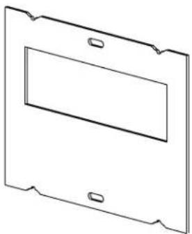
natural_image
Simple line drawing of a rectangular frame with two side handles and a central rectangular cutout (no text or symbols)[03] × 2

natural_image
Simple 3D line drawing of a long rectangular object with no text or symbols[04] x 2

natural_image
Simple line drawing of a rectangular plate with a small notch on top (no text or symbols)[05] x 1

natural_image
Pure technical line drawing of a rectangular beam with evenly spaced circular holes (no text or symbols)[06] x 2

[07] x 1

[08] x 1
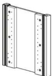
natural_image
Pure technical line drawing of a rectangular panel with vertical supports and bolt holes (no text or symbols)[09] x 2

natural_image
Simple line drawing of a rectangular frame with a vertical edge and horizontal edges (no text or symbols)[10] x 2

[11] x 2

[12] x 4

[13] x 4
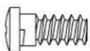
[14] x 8
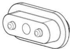
natural_image
Technical line drawing of a mechanical bracket or housing component (no text or symbols)[15] x 2

[16]×2

[17] x 4

[18] x 2

[19]×4
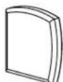
[20] x 4

[21] × 2

[22] × 4

[23] × 2

[24] × 2

[25] × 4

[26] x 4

[27] × 8

[28] x 4
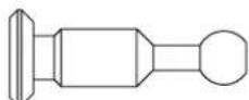
[29] × 8

[30] x 4

[31] x 4
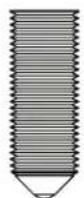
[32] x 4
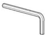
[33] x 1
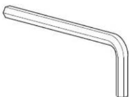
natural_image
Simple line drawing of a bent pipe or elbow joint (no text or symbols)[34] x 1
![1 [09] [09] [19]](/content/2026/06/1249246/images/21ed30a8a29df6be772ac6cd2fd7a7d30346233bbdfe728e8a7732daa11caefa.jpg)
NOTE: The bottoms of the side panels are even. Be sure to attach feet to the even bottoms of the side panels.
![2 [06] 90° 90° 4x [29]](/content/2026/06/1249246/images/a04d86925a561e928329f6ba0af246bcafb9f0878685ee8c2088def36f263243.jpg)
2.1

CauTION
Back Braces [06] must be inserted as shown. Once in place, be sure the bottom brace is even with the tops of the feet [19], and the top brace with the tops of the side panels [09].


2.2

CauTION
Front braces (4) must be inserted slot-down, as shown. Once in place, be sure the bottom brace is even with the tops of the feet [19], and the top brace with the tops of the side panels [09].
![[04] [09] [04] [09] 4x [04] [33]](/content/2026/06/1249246/images/a427937572bbeafcb779b308e9c4e0cdbce19fce00b3e81a21e5dedbebcc9a91.jpg)
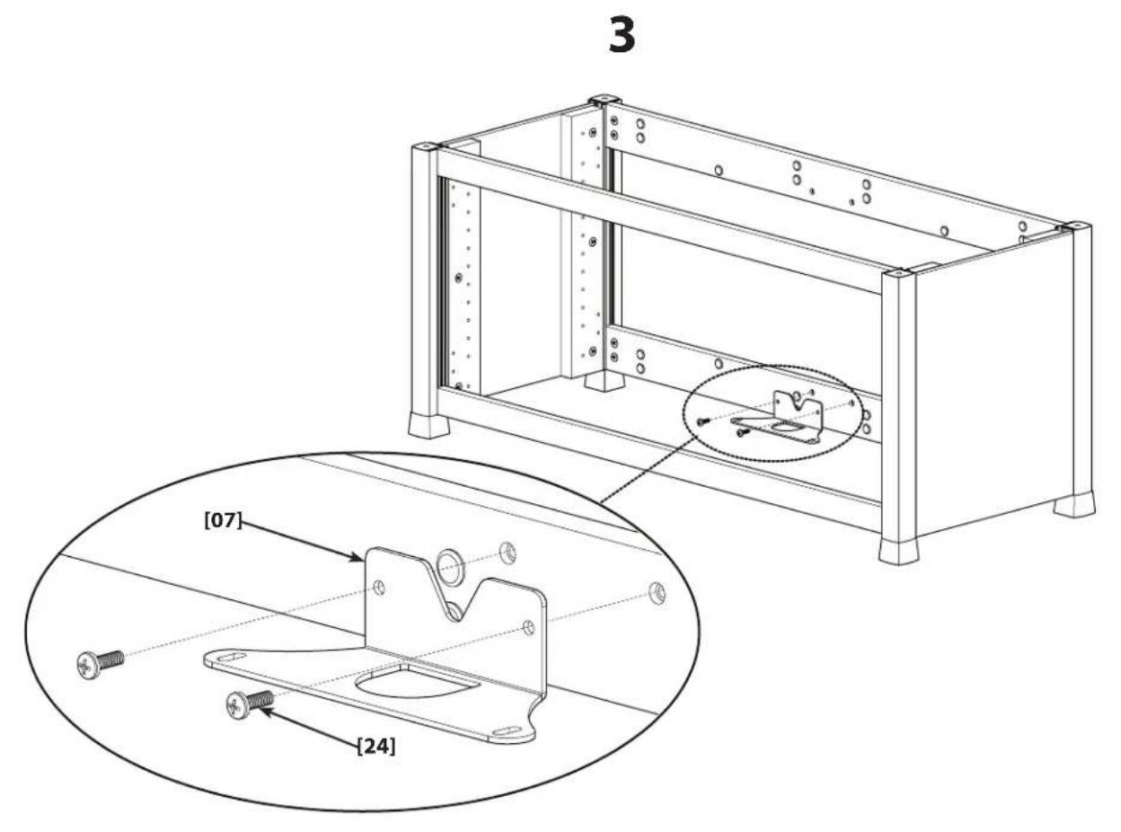
3.1
![[05] [04] [26] 4x](/content/2026/06/1249246/images/9de01399cbc3faea3ccab7f132e3a66055a2fa1447cedd3f2e3c910ac670b86b.jpg)
6901-100094 <01>
3.2
![[08] [25] [07] [25] [31] [32] 4x CauTION Carpet spikes [32] are sharp. OPT [20]](/content/2026/06/1249246/images/b0978917b0579c4560ed56548ff74e9022319107a5e798a11998a481d3d0cea5.jpg)
![4 [02] 4x [28]](/content/2026/06/1249246/images/47be86bcc3a9f9d80e5c26030739824f99c0bbe5831603ed701edc3be1ae67f0.jpg)
![6901-100094 <01> [18] [23] 5 4x [10] [12] [27]](/content/2026/06/1249246/images/626a5e3aed3428703cf559ecd5f339ce74cf0af17e8e4eae4a4217bdc1b6882d.jpg)
5.1
![4x [13] [14]](/content/2026/06/1249246/images/437dd61384cba8d1952a12615efbd50892c75419f981c2d1369e2e9da8cf5677.jpg)
5.2
![[12] [13] 4x](/content/2026/06/1249246/images/3bf4ea8c1f24d474f98eea52740d2b0f0a2c4b9c4762182d66e3d6460ce825fa.jpg)
6901-100094 <01>
5.3
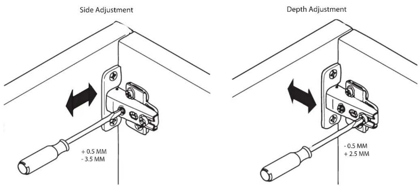
Height Adjustment

6
![[01] [30]](/content/2026/06/1249246/images/e04b8f1affd08e3bb0dc4b7e1dc229f5f4a260ddd8d0536261675eed0e045344.jpg)
6.1
![[01] [30]](/content/2026/06/1249246/images/c38af0213fe62015d569cf7db358a49b371c0010c2d4a17279edba45f8028c35.jpg)
7

natural_image
Technical line drawing of a mechanical component enclosed in a circular outline (no text or symbols)
natural_image
Prohibition symbol of a mechanical component with three circular holes and a diagonal line crossing through it (no text or labels)![2x [16] [21] [15] [22] [17] 4x](/content/2026/06/1249246/images/2f90266823b0a6d4f967db79eaf360781f0aec0ed33280cdc08241deba72831e.jpg)
![7.1 [03] [03] OPT [03] [03]](/content/2026/06/1249246/images/13d4665efe386957723a4a7609f1fd4f1731e83a6064713b558669a421550875.jpg)

Milestone AV Technologies, Inc. and its affiliated corporations and subsidiaries (collectively, "Milestone"), intend to make this manual accurate and complete. However, Milestone makes no claim that the information contained herein covers all details, conditions, or variations. Nor does it provide for every possible contingency in connection with the installation or use of this product. The information contained in this document is subject to change without notice or obligation of any kind. Milestone makes no representation of warranty, expressed or implied, regarding the information contained herein. Milestone assumes no responsibility for accuracy, completeness or sufficiency of the information contained in this document.


Brand : SANUS
Model : CFV47
Category : TV Stand