
FV350 - Access Control ZKTeco - Free user manual and instructions
Find the device manual for free FV350 ZKTeco in PDF.


| Product Type | Biometric Access Control Terminal |
| Brand | ZKTeco |
| Model | FV350 |
| Dimensions (W x H x D) | Approx. 208 × 83 × 71 mm |
| Weight | Approx. 0.33 kg |
| Power Supply | 12V DC, 3A |
| Display | 2.8-inch TFT LCD |
| Fingerprint Sensor | Optical, 500 DPI |
| Face Recognition | Visible light, dual camera |
| User Capacity | Up to 3,000 users |
| Fingerprint Capacity | Up to 3,000 templates |
| Face Capacity | Up to 1,000 templates |
| Communication | TCP/IP, USB Host, Wi-Fi (optional) |
| Access Control Interfaces | Lock, door sensor, exit button, alarm |
| Card Reader | RFID (125kHz / 13.56MHz) |
| Operating Temperature | 0°C to 45°C |
| Protection Rating | IP54 (front panel) |
| Maintenance | Clean sensor with soft dry cloth; avoid solvents |
| Security Features | Fake fingerprint detection, live face detection |
| Spare Parts Availability | Power adapter, mounting bracket, screws |
| Repairability | Replaceable power supply board and sensor module |
Frequently Asked Questions - FV350 ZKTeco
User questions about FV350 ZKTeco
0 question about this device. Answer the ones you know or ask your own.
Ask a new question about this device
Download the instructions for your Access Control in PDF format for free! Find your manual FV350 - ZKTeco and take your electronic device back in hand. On this page are published all the documents necessary for the use of your device. FV350 by ZKTeco.
USER MANUAL FV350 ZKTeco
Control Series Product
Version: 1.0.1
Date: July, 2015
About This Manual
This document describes the user interfaces and menu functions of the finger vein product series. This document can be used in combination with the Access3.5 software. For product installation, please see the start guide of the product.
- The pictures in this manual may not be exactly consistent with those of your product; the actual product's display shall prevail.
- Only some devices are equipped with the functions; the actual product shall prevail.
Important Statement
Thank you for choosing our product. Before starting to use it, please read this manual carefully to avoid damage to the device. We remind you that through proper use, you may experience good effect and verification speed.
No part of this document can be extracted, copied or transmitted by any means without prior written consent of our Company.
The products described in this manual may contain software belonging to SANGFOR or licensors possessing copyright. Unless permitted by obligees, no one can copy, distribute, modify, extract, decompile, disassemble, decode, reverse engineer, rent, transfer, sub-license such software in any form or conduct other behaviors infringing software copyright, exclusive of cases with prohibition of such limitation by applicable laws.

Due to product update, our Company does not promise the consistency of the manual with actual products, and not assume responsibilities for any dispute arising from the discrepancy between actual technical parameters and this manual. The manual is subject to change without prior notification.
Contents
1 Guidance Notes....1
1.1 Product Functions....1
1.2 Modes of Enrollment and Verification of Finger Veins & Fingerprints★....2
1.3 Method of Pressing Fingerprint★ 4
1.4 Usage of the Touch Screen....4
1.5 Verification Modes....5
1.5.1 Finger Vein and Fingerprint Verification ★ 5
1.5.2 Password Verification....6
1.5.3 Card Verification★ 7
1.5.4 Combined Verification....8
1.5.5 Combined Verification for Unlocking....9
1.6 Product Appearance and Terminal Blocks....10
1.6.1 Product Appearance....10
1.6.2 Terminal Blocks....11
1.7 Initial Interface....11
2 Main Menu....13
3 User Management ....15
3.1 Adding a User....15
3.1.1 Entering a User ID....16
3.1.2 Entering a Name....16
3.1.3 User Role 17
3.1.4 Registering a Finger Vein and Fingerprint....18
3.1.5 Enrolling a Badge Number ★....19
3.1.6 Enrolling a Password....19
3.1.7 Setting Access Control Level 20
3.2 All Users 21
3.2.1 Querying a User....22
3.2.2 Editing/Deleting a User 22
3.3 Display Style....23
4 User Role....25
5 Comm. Settings....28
5.1 Ethernet Settings....28
5.2 Serial Comm. Settings....29
5.3 PC Connection....29
5.4 Wiegand Setup....30
5.4.1 Wiegand Input 30
5.4.2 Wiegand Output....32
5.4.3 Card Format Detect Automatically....33
6 System Settings....34
6.1 Date/Time Settings 34
6.2 Access Logs Setting★ 35
6.3 FV&FP Parameter Setting★ 35
6.4 Reset to Factory Settings....36
6.5 USB Upgrade....36
7 Personalize Settings....38
7.1 User Interface Settings....38
7.2 Voice Settings....40
7.3 Bells Settings....40
7.3.1 New Bell Schedule....41
7.3.2 All Bell Schedules....42
8 Data Mgt. 43
8.1 Delete Data....43
8.2 Backup Data 44
8.3 Restore Data 45
9 Access Control....47
9.1 Access Control Options Settings....47
9.2 Time Schedule Settings....48
9.3 Holidays Settings....50
9.3.1 Add Holiday....50
9.3.2 Include Holidays....52
9.4 Combined Verification Settings....52
9.5 Anti-passback Settings....53
10 USB Manager....55
10.1 USB Download....55
10.2 USB Upload....56
11 Attendance Search....57
12 Autotest....58
13 System Information....59
Appendices....61
Appendix 1 Text Input Operation Instructions....61
Appendix 2 USB....62
Appendix 3 Wiegand Introduction....62
Appendix 3.1 Wiegand 26 Introduction....63
Appendix 3.2 Wiegand 34 Introduction....64
Appendix 4 Anti-passback Settings....66
17.7 Statement on Human Rights and Privacy 68
17.8 Environment-Friendly Use Description....69
1 Guidance Notes
Do not expose the device under strong direct sunshine, because strong light has adverse impact on the vein image collector. The operating temperature of the device ranges from 0^ C to 40^ C and heat dissipation of the device together may compromise its performance, which results in slower response and passing rate. If the device needs to be used outdoors, a housing or heat-radiating equipment is recommended.
The recommended installing height (vertical distance from the ground to the doorbell) the device is 1.4 m based on the user group with the height ranging 1.55 m to 1.75 m. The installation height can be adjusted based on users' average height so that the users press veins and fingers conveniently.
1.1 Product Functions
● Special Functions (Logic of Firmware Application)
1. Finger vein function
The finger vein identification technology is a new technology of biological characteristic identification. It recognizes identities by using images of vein distribution in fingers, and has the features of uniqueness, stability, high identification accuracy, and anti-counterfeiting.
The finger vein function supports enrolling, deletion, verification, and uploading and downloading of finger vein templates via a USB disk or software.
2. User access control
An access control logic adopting a controller has the following functions:
Setting users' valid dates
Setting users' effective time periods
(3) Supporting multiple user verification methods
(4) Setting effective time periods for doors
(5) Setting time periods for door opening
(6) Setting time periods for holidays
(7) Setting the first-card normal open
(8) Setting anti-passback time periods
(9) Setting in/out anti-passback
(10) Keeping controller access control records
(11) Supporting auxiliary input
(12) Supporting Wiegand master and slave device functions
3. USB disk function
You may download user data and access control records to a USB disk and upload user data, promotion pictures and wallpapers in USB disk to the device.
4. Communication over RS485 or Ethernet
The device communicates with the Access3.5 software over the RS485 protocol or Ethernet (TCP/IP).
1.2 Modes of Enrollment and Verification of Finger Veins & Fingerprints★
Note: While enrolling a finger vein, the device also registers the fingerprint of the selected finger.
1. Recommended fingers: index finger and middle finger

2. Finger placement
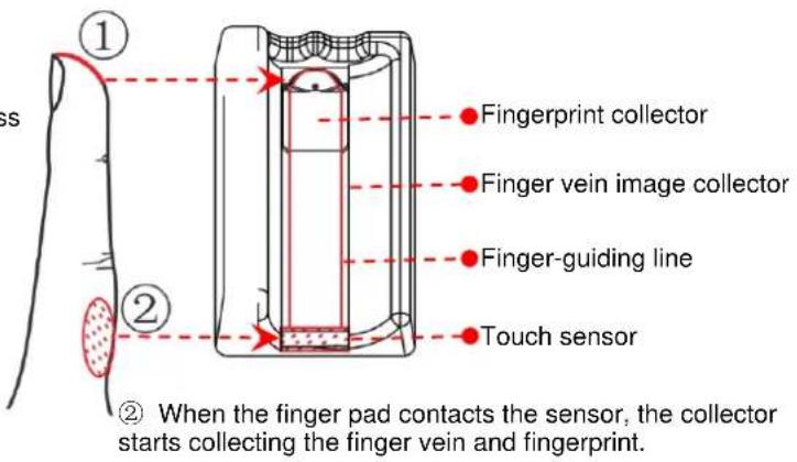
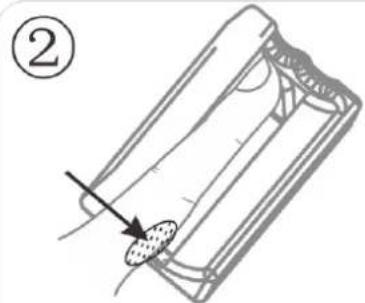
(1) Touch the front end of the finger vein image collector with a fingertip, flatly press the finger pulp against the fingerprint collector so that the device collects the finger vein and fingerprint.
3. Vein verification procedure
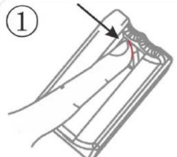
Ensure that the fingertip touches the front end of the finger vein image collector, and flatly press the finger pulp against the fingerprint collector.
natural_image
Cross-sectional diagram of a mechanical component with a red outline and a black checkmark (no text or symbols)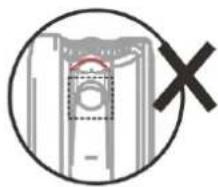
natural_image
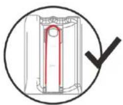
Cross-sectional diagram of a mechanical component with no visible text or symbolsEnsure that the fingertip touch the front end of the finger vein image collector. Otherwise, the images of the finger vein and fingerprint cannot be collected correctly.
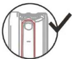
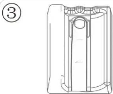
Lay down the finger along the guiding line, keep it in the middle, with the finger pad contacting the sensor.
natural_image
Cross-sectional diagram of a mechanical component with a red highlighted section and a black checkmark (no text or symbols)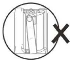
natural_image
Simple line drawing of a mechanical component inside a circle with a black X mark (no text or symbols)Correct images of the finger vein and fingerprint cannot be collected if the finger is slanted.
natural_image
Technical line drawing of a mechanical component with no visible text or symbols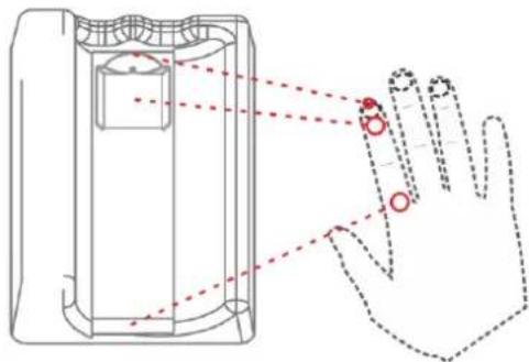
natural_image
Diagram of a hand holding a device with red circular markers pointing to the fingers (no text or symbols present)After the finger pad contacts the sensor, the collector starts collecting the finger vein image. Keep the finger in place until you hear a "Bi" sound, and then move away the finger.

- Stretch your hand naturally without force.
- Stretch the finger flat, and try not to bend or rotate it.
- You do not need to press the finger against the collector with force.
1.3 Method of Pressing Fingerprint★
It is recommended to use the index finger, middle finger or ring finger; avoid using the thumb or little finger.
1. Correct way to press the fingerprint:
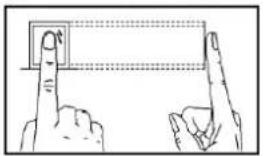
Press the finger horizontally onto the fingerprint sensor; aiming the fingerprint center to that of the sensor.
2. Wrong ways to press the fingerprint:
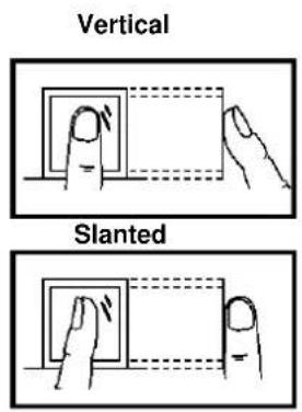
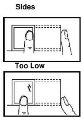
1.4 Usage of the Touch Screen
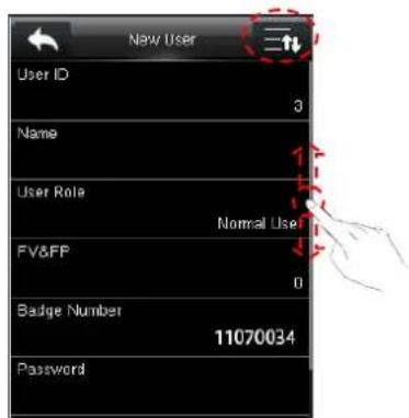
You may click the touch screen, or click and slide it using a finger pulp. Clicking the screen with a fingertip or fingernail may compromise the use effect.

natural_image
Illustration of two hand-drawn symbols: a blue circle on a diagonal line and an orange X on a vertical line, both without any text or labels.Click ☐ to scroll up/down a screen, or drag the scroll bar on the right.
1.5 Verification Modes
1.5.1 Finger Vein and Fingerprint Verification ★
◆ 1:N verification
The finger vein image and fingerprint collected by the collector are compared with all finger vein images and fingerprints in the device.
- The device automatically detects finger vein or other verification modes. When a finger contacts the finger vein sensor, the device enters the finger vein and fingerprint verification mode. (Note: For the position of the finger vein sensor, see 1.6.1 "Product Appearance.")
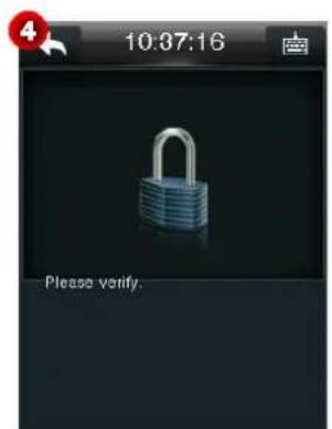
- Press a finger onto the collector correctly. For details, see 1.2 "Modes of Enrollment and Verification of Finger Veins & Fingerprints."
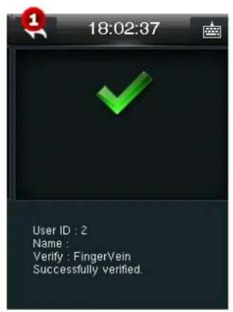
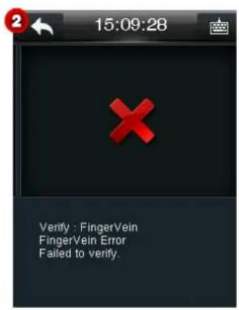
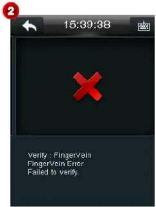
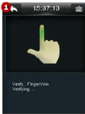
- After the device generates a "Bi" sound, remove the finger. If the verification succeeds, the device plays the voice prompt "Thank you." and "Successfully verified." is displayed on the screen. If the verification fails, the device plays the voice prompt "Please repress your finger." and "Failed to verify." is displayed on the screen.
◆ 1:1 verification
The finger vein image and fingerprint image currently collected by the collector are compared with the finger vein image and fingerprint image associated with the user ID entered via the keypad. This mode is used when users have difficulty in verifying finger veins and fingerprints.
-
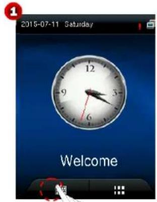
On the initial interface, click 📄 to enter the interface for entering a user ID.
-
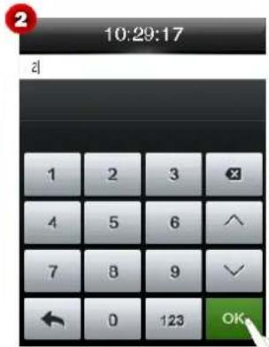
Enter a user ID, and click OK (see Figure 2) to enter the interface for selecting a verification mode.

Note: If "No enrollment data" is prompted, the user ID does not exist.
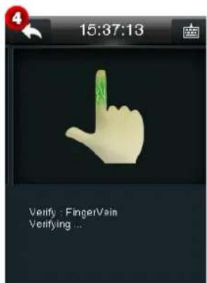
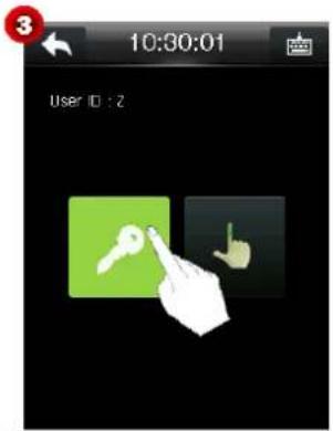
- Click the finger vein icon (see Figure 3) to enter the 1:1 finger vein (fingerprint) verification interface.
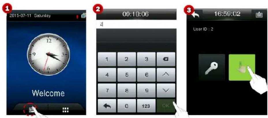
- Press a finger onto the collector correctly. For details, see 1.2 "Modes of Enrollment and Verification of Finger Veins & Fingerprints."
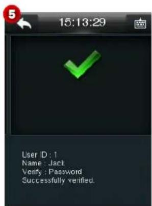
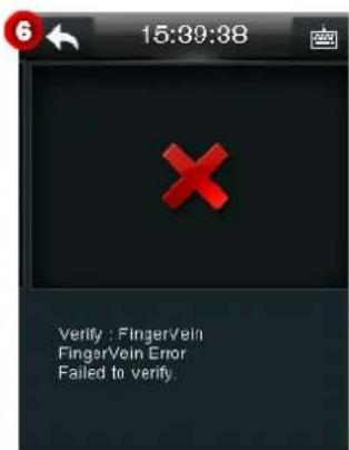
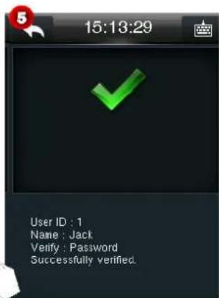
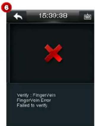
- After the device generates a "Bi" sound, remove the finger. If the verification succeeds, the device plays the voice prompt "Thank you." and "Successfully verified." is displayed on the screen (see Figure 5). If the verification fails, the device plays the voice prompt "Please repress your finger." and "Failed to verify." is displayed on the screen (see Figure 6).
1.5.2 Password Verification
- On the initial interface, click 📄 to enter the interface for entering a user ID.
- Enter a user ID, and click OK (see Figure 2) to enter the interface for selecting a verification mode.

Note: If "No enrollment data" is prompted, the user ID does not exist.
- Click the key icon (see Figure 3) to enter the password verification interface.
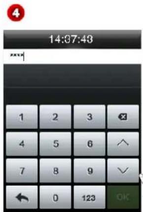
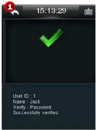
- On the displayed interface, enter a password, and click OK. If the verification succeeds, the device plays the voice prompt "Thank you." and "Successfully verified." is displayed on the screen. If the verification fails, the device plays the voice prompt "Wrong password." and "Failed to verify." is displayed on the screen.
1.5.3 Card Verification★
- The card function is optional. Only products with built-in card modules are equipped with the card verification function. Some devices support Mifare cards as ID cards.
- If the verification succeeds, the device plays the voice prompt "Thank you." and "Successfully verified." is displayed on the screen. If the verification fails, the device plays the voice prompt "ou ou" and "Failed to verify." is displayed on the screen.
1.5.4 Combined Verification
The device supports combined verification, such as finger vein & password, in which the device needs to verify the password/finger vein after a user passes the finger vein/password verification.
Take the finger vein & password verification for example. Suppose that a user first performs finger vein verification.
- Press a finger onto the collector correctly. For details, see 1.2 "Modes of Enrollment and Verification of Finger Veins & Fingerprints."
- After the device generates a "Bi" sound, remove the finger. After the finger vein verification is passed, the password verification interface is displayed (see Figure 2).
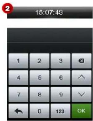
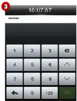
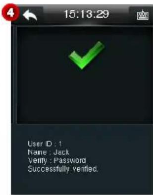
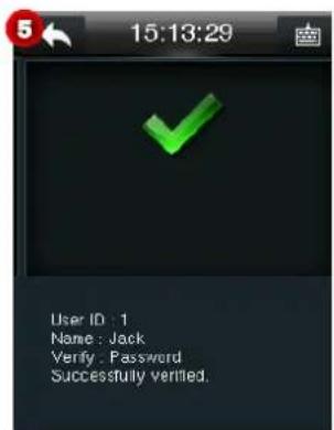
- Input the correct password, and click OK. When the password verification is passed, "Successfully verified." is displayed (see Figure 4).
Note: Users may set verification modes as needed. For specific operations, see 9.1 "Access Control Parameters."
1.5.5 Combined Verification for Unlocking
Notes:
(1) For details about how to set combined verification for unlocking, see 9.4 "Combined Settings for Unlocking."
(2) On the interface of adding/editing a user, administrators can specify a group to which a user belongs, and add the user to the group for unlocking. For detailed operation methods, see 3.1.7 "Setting Access Control Level."
For example, add a unlocking combination requiring simultaneous verification of user group 1 and user group 2 (see Figure 1), and add users to the user groups for unlocking.
Suppose that the user with the user ID of 1 belongs to user group 1, and the user with user ID of 2 belongs to user group 2.
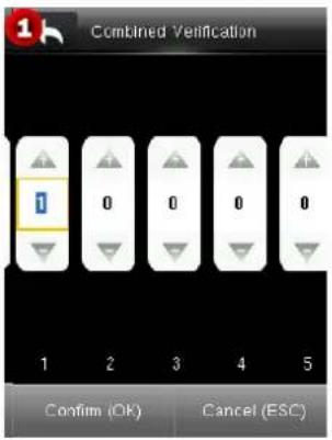
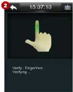
- The user with the user ID 1 presses a finger onto the collector correctly. For details, see 1.2 "Modes of Enrollment and Verification of Finger Veins & Fingerprints."
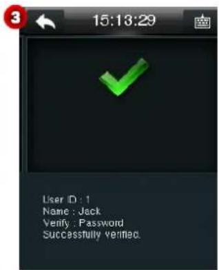
- After the device generates a "Bi" sound, remove the finger. After the finger vein verification is passed (see Figure 3), the device displays the prompt "Multi-user verification" (see Figure 4).
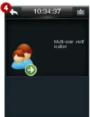
- The user with the user ID 2 presses a finger onto the collector correctly. After the device generates a "Bi" sound, remove the finger. After the verification is passed, "Successfully verified." is displayed on the screen and the device plays the voice prompt "Thank you."
1.6 Product Appearance and Terminal Blocks
1.6.1 Product Appearance
- Front view of the finger vein & fingerprint product Front view of the finger vein product
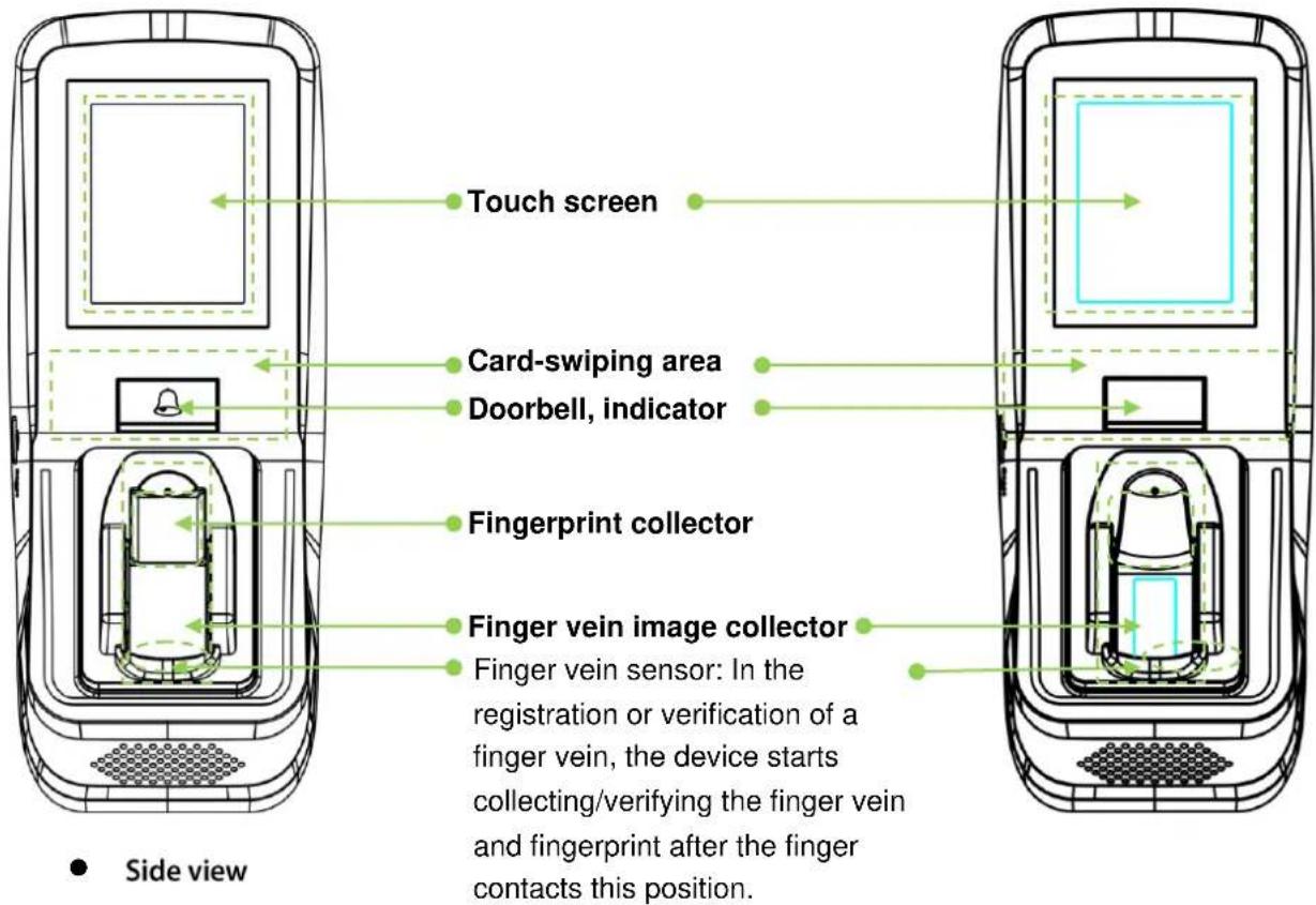
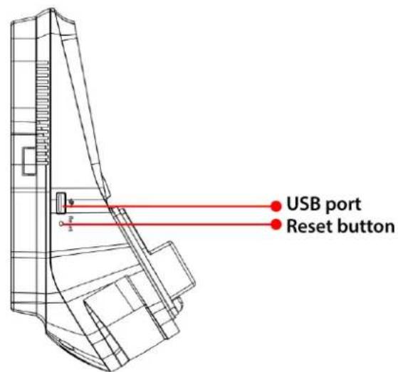
Reset button: After the device is powered on for 30 seconds, press this button using a sharp-end tool with a diameter of less than 2 mm to reset the device.
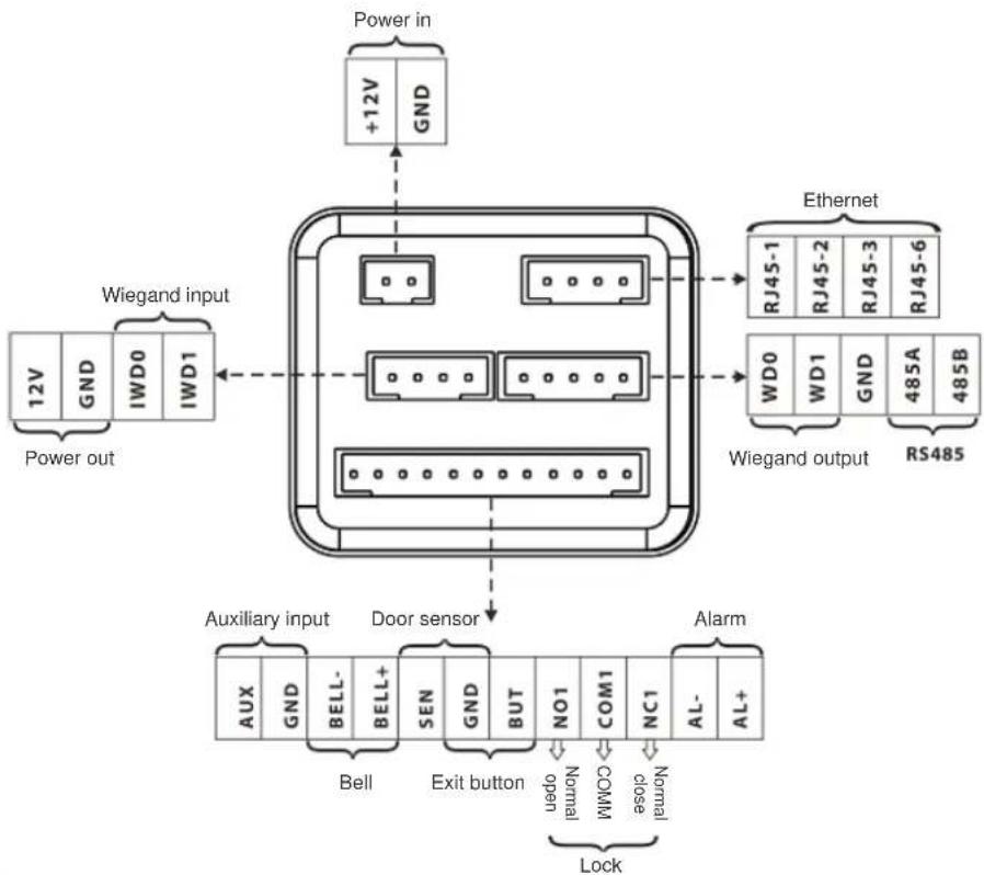
1.6.2 Terminal Blocks
flowchart
graph TD
    A["Power in"] --> B["+12V GND"]
    B --> C["Wiegand input"]
    C --> D["12V GND IWD0 IWD1"]
    D --> E["Power out"]
    F["Ethernet"] --> G["RJ45-1 RJ45-2 RJ45-3 RJ45-6"]
    G --> H["WD0 WD1 GND 485A 485B"]
    H --> I["Wiegand output"]
    I --> J["RS485"]
    K["Auxiliary input"] --> L["Door sensor"]
    L --> M["AUX GND BELL-BELL+ SEN GND BUT NO1 COM1 NC1 AL-AL+"]
    L --> N["Bell"]
    L --> O["Exit button"]
    P["Alarm"] --> Q["Lock"]
    R["Power in"] --> S["+12V GND"]
    S --> T["Wiegand input"]
    T --> U["12V GND IWD0 IWD1"]
Power input: Use the attached standard power adapter. The power voltage is DC 12 V, and the current is not lower than 3A. Do not user other power supply to avoid damage to the device.
Ethernet port: a network interface, through which the device can be connected to network equipment such as a switch, router or hub.
Auxiliary input port: connected to a smoke alarm to receive alarm signals.
1.7 Initial Interface
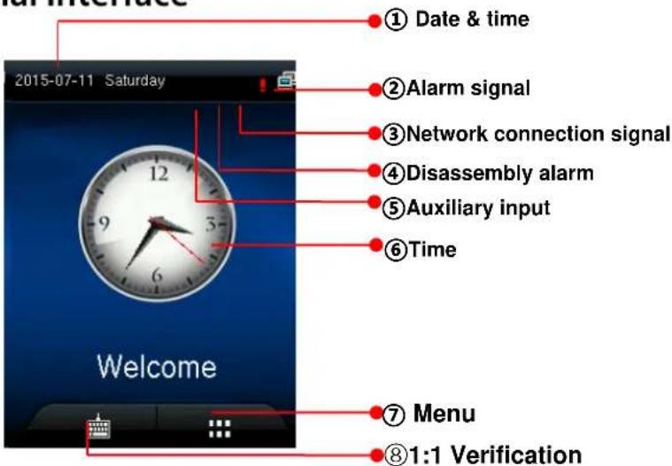
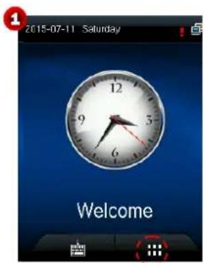
① Date: The current date of the device is displayed.
② Alarm signal: An alarm is set for the device if this icon is displayed.
③Network connection signal: The network connection status of the device is displayed.
④Disassembly alarm: The disassembly alarm button is up if this icon is displayed, and the possible cause is "improper installation" or "illegal disassembly".
⑤ Auxiliary input: This icon is displayed when the auxiliary input terminal of the device is connected to an auxiliary device and the auxiliary input condition is triggered.
⑥Time: The current time of the device is displayed. The 12-hour and 24-hour systems are supported. Users may customize the style of the main interface. For details, see personalized settings.
⑦Menu: Press this icon to enter the main menu. If administrators are set for the device, you should pass the administrator verification before accessing the main menu.
⑧1:1 Verification (soft keyboard): Press the key to enter the interface for inputting a user ID in 1:1 verification mode. After inputting a user ID, click OK and complete the 1:1 verification according to prompts on the interface.
2 Main Menu
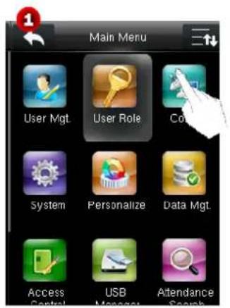
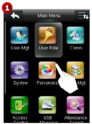
On the initial interface, click 🎨 to enter Main Menu (see Figure 2). Click 🎨 to scroll down the screen (see Figure 3) to display more content. (Note: You can click 🎨 again to scroll up the screen.)
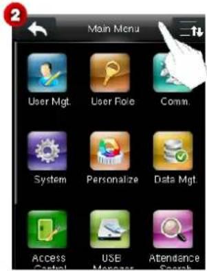
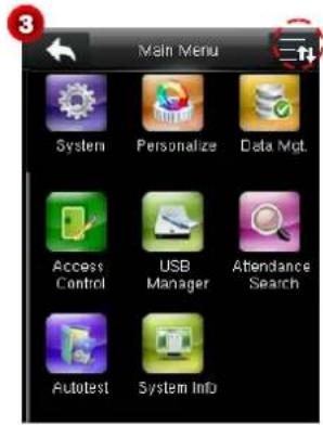
There are 12 sub-menus under the main menu.
| User Mgt. | To add and manage users, browse user information (including user IDs, names, user roles, finger vein images, fingerprints, badge numbers ★, passwords, and access control level), and add, query, modify or delete such information. |
| User Role | User Role: To set user roles for accessing the menu and changing settings. |
| Comm. | To set the related parameters of the communication between the device and PC, including Ethernet parameters such as IP address etc., serial Comm, PC connection and Wiegand settings. |
| System | To set system-related parameters and firmware upgrade, including time, access control records, parameters of finger veins and fingerprints and factory settings restoration, so that the device meets user requirements to the maximum extent in functions and display. |
| Personalize | This includes interface display, voice, bell, punch state key mode and shortcut key settings. |
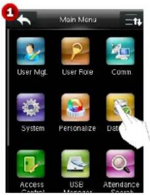
| Data Mgt. | To delete attendance data, all data, super admin role or screen savers etc. |
| Access control | To set the parameters of the control lock and access control devices, including parameters of access control, time rules, holidays, combined unlocking, and anti-pass. |
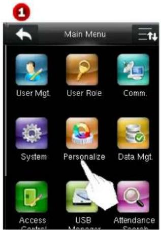
| USB Manager | To transfer data such as user data and attendance logs from the USB disk to the supporting software or other devices. |
| Attendancesearch | To query the records saved in the device after successful verification. |
| Autotest | To automatically test different module's functions, including the LCD, voice, keyboard, fingerprint sensor, camera★ and clock RTC test. |
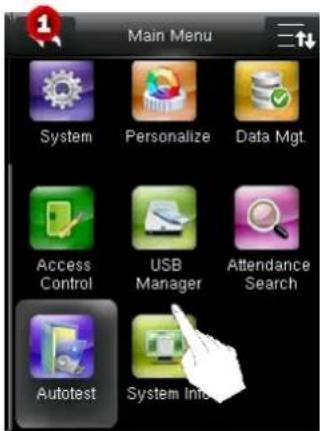
| System Info | To check device capacity, device and firmware information. |

When no administrator is set, anyone may access the main menu by clicking 🎯 After an administrator is set, a user should pass the administrator identity verification before entering the menu.
For the sake of security, it is recommended that an administrator be registered when the device is used for the first time.
3 User Management
The basic user information registered in the device includes user IDs, names, user roles, finger vein images and fingerprints★, passwords, badge numbers ★, and access control level. Such information is subject to change due to personnel changes, and therefore the device supports the adding, deleting, query and modifying operations.
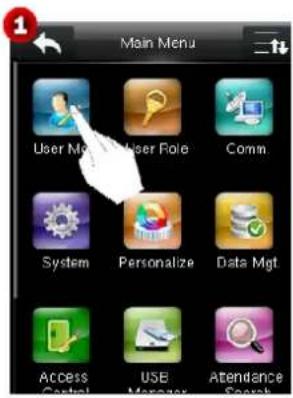
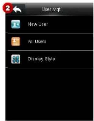
3.1 Adding a User
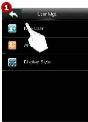
On the User Mgt. interface, click New User to enter the New User interface, and click 📄 to scroll down the screen to display more content. (Note: You can click 📄 again to scroll up the screen.)
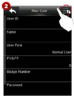
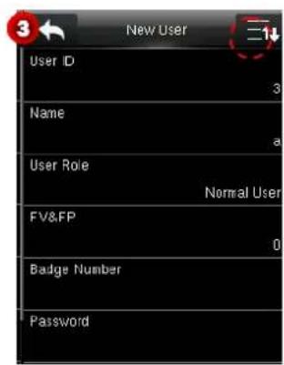
User ID: Enter a user ID. By default, 1-9 digits are supported.
Name: Enter a user name. By default, 1-24 characters are supported. One Chinese character takes up two characters.
User Role: Set user roles. The default value is Normal User. You may choose Super Admin. A normal user can only use verification by finger vein, fingerprint ★, badge ★ or password, while an administrator has all the functions of normal users and the access to the main menu.
FV&FP ★: Enroll a finger vein and fingerprint. Index and middle fingers are recommended.
Password: Enroll a password. By default, 1-8 digits are supported.
Badge Number ★: Enroll a badge number.
Access Control Level: Set a user's access control level.
3.1.1 Entering a User ID
The device automatically assigns user IDs to users, starting from 1. If you use a device-assigned number, skip this step.
- On the New User interface, click User ID.
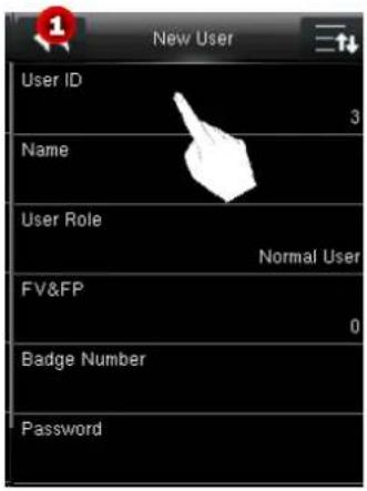
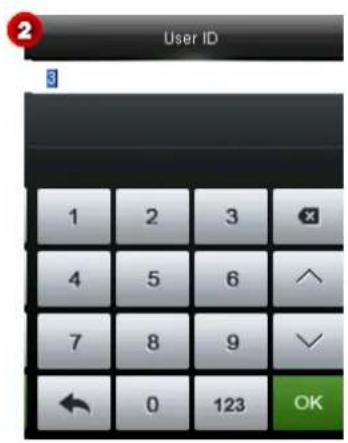

Tips: Enrolled user IDs cannot be modified.
- On the displayed interface, enter a user ID to be registered, and click OK to save the setting and return to the New User interface. If "User ID exists!" is displayed, it indicates that the user ID has been used. Please enter another ID.

Tips: By default, user IDs of 1-9 digits are supported. To extend digits, consult our business representatives or pre-sales technical support personnel.
3.1.2 Entering a Name
Enter a user name by using the T9 input method via keypad.
-
On the New User interface, click Name.
-
On the displayed interface, enter a user name to be registered. Click words to select them.
For operations on the keypad interface, see Appendix 1 Text Input Operation Instructions.
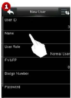
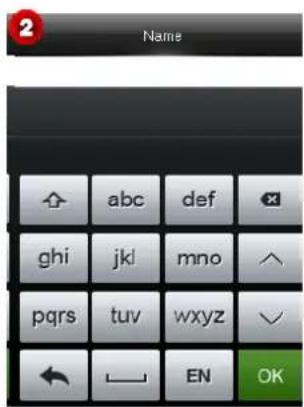
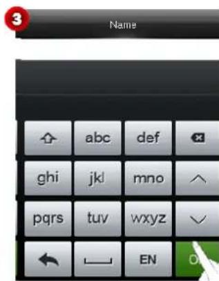
- After entering a name, click OK to save the setting and return to the New User interface. If you click ↗, the device returns to the upper-level interface without saving the information.
Tips: By default, names of 1-24 characters are supported. One Chinese character takes up two characters.
3.1.3 User Role
The device supports two user roles: Normal User and Super Admin.
Super Admin: A super administrator is permitted to perform operations on all the menus.
Normal User: When an administrator is set, a normal user can use only finger vein (fingerprints ★), passwords or badges ★ for verification. When no administrator is set, a normal user is permitted to perform operations on all the menus.
User Defined Role: After a super administrator is set, you can define roles in User Role and assign menu operation rights to the roles. User-defined roles possess all the rights of a normal user, that is verification via finger vein (fingerprint ★), password and badge.

indicates the current user is an administrator.
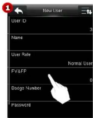
- On the New User interface, click User Role.
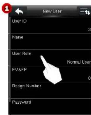
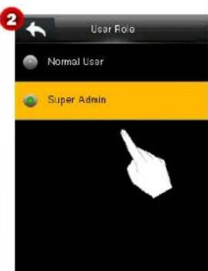
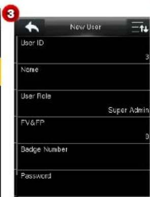
- Select a role as needed. Then, the device returns to the New User interface.
Note: After a super administrator is added, you need to pass the super administration verification before accessing the main menu.
3.1.4 Registering a Finger Vein and Fingerprint
Note: While enrolling a finger vein, the device also registers the fingerprint of the selected finger.
- On the New User interface, click FV&FP to enter the Register FV& FP interface (see Figure 2).
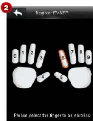
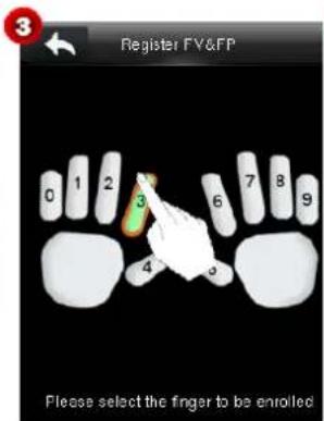
- On the displayed interface, click a finger to enroll the finger vein and fingerprint (see Figure 3).
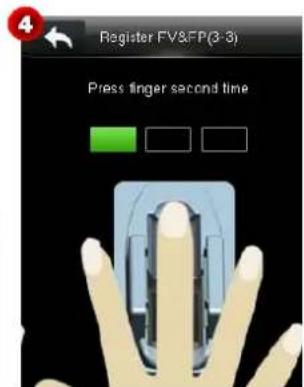
- Press the same finger onto the collector correctly for consecutive three times as according to prompts on the device (see Figure 4). For details, see 1.2 "Modes of Enrollment and Verification of Finger Veins."
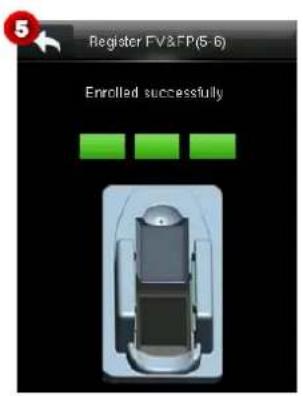
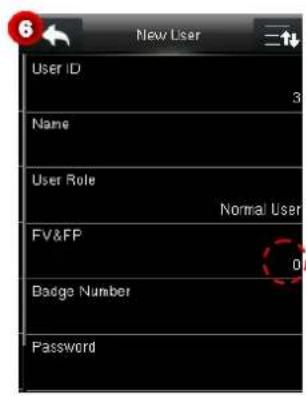
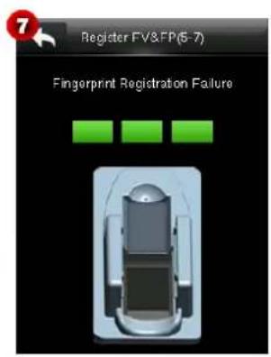
After the finger vein and fingerprint are successfully collected for three times, "Enrolled successfully." is displayed on the screen (see Figure 5), and the device returns to the New User interface displaying the quantity of registered veins and fingerprints (see Figure 6). If the collection fails, "Fingerprint Registration Failure" is displayed (see Figure 7). To continue registration, repeat steps 2 and 3.
Notes:
(1) During enrollment of veins and the fingerprint, a "Bi" sound generated by the collector indicates that single collection is successful.
(2) For better collection of veins and fingerprints, remove the finger after successful collection each time (after a "Bi" sound is generated), and continue the enrollment by pressing the finger again as instructed.
3.1.5 Enrolling a Badge Number ★
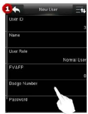
- On the New User interface, click Badge Number to enter the Enroll Badge Number interface (see Figure 2).
- Swipe a badge over the area. For details about the card-swiping area, see the mark in 1.6.1 "Product Appearance."
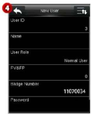
- After the card is read successfully, the badge number is displayed (see Figure 3) and the device returns to the New User interface (see Figure 4).
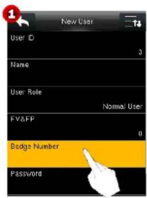
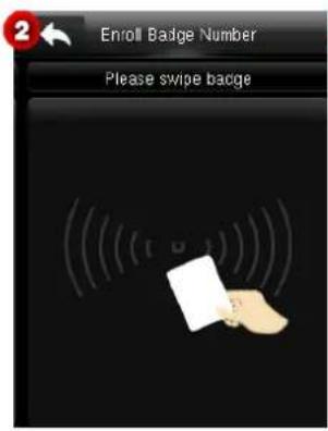
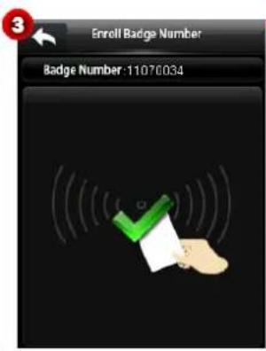
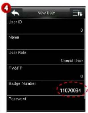

Note: Some devices support Mifare cards as ID cards.
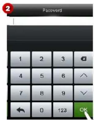
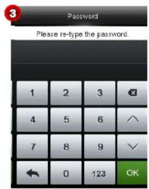
3.1.6 Enrolling a Password
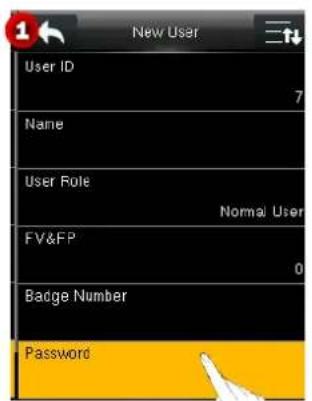
- On the New User interface, click Password.
- On the displayed keypad interface, enter a password and click OK (see Figure 2).

Tips: By default, passwords of 1-8 digits are supported.
- Re-enter the password as instructed, and click OK to save the password (see Figure 3). After successfully saving the password, the device returns to the New User interface (see Figure 4).
Notes:
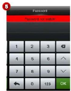
(1) The passwords entered in steps 2 and 3 must be the same. Otherwise a prompt box (see Figure 5) is displayed.
(2) If you enter inconsistent passwords, you need to return to step 2 and enter it again.
3.1.7 Setting Access Control Level
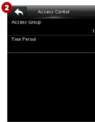
On the New User interface, click Access Control to enter the Access Control interface (see Figure 2).
The access control level is used to set level of door opening for each user, including the access group and time period rules.
- Setting an access group
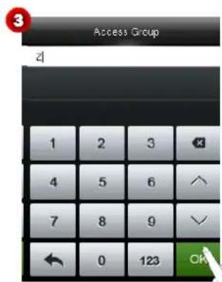
Set a user group to which a user belongs, to facilitate unlocking combination settings. A valid group number ranges from 0 to 99999999.
(1) On the Access Control interface, click Access Group.
(2) Enter the number of the group to which the user belongs, and click OK (see Figure 3) to save the settings and return to the Access Control interface.
- Setting a time period
Select time rules for the user. Time rules are set under the Access Control menu and a maximum of 50 time rules are supported. The effective door opening time period of the user is the sum of the selected time rules.
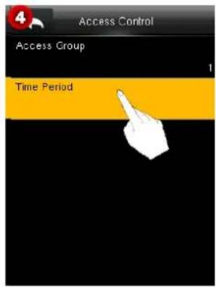
(1) On the Access Control interface, click Time Period to enter the Time Period interface (see Figure 4). Click to scroll up/down the screen to display more content.
(2) In the time rule list, click and select a time rule (multiple selections are allowed and the symbol ☑ indicates that a time rule is selected), and click 📄 (see Figure 5) to save the settings and return to the previous interface.
![Time Period Time Rule [1] Time Rule [2] Time Rule [3] Time Rule [4] Time Rule [5] Time Rule [6]](/content/2026/05/979491/images/04b1ab5152cdf51bf79fb7ce55978219b582626d56e812694fa52d59a6c33357.jpg)
3.2 All Users
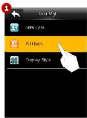
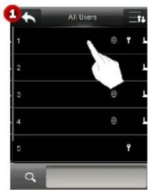
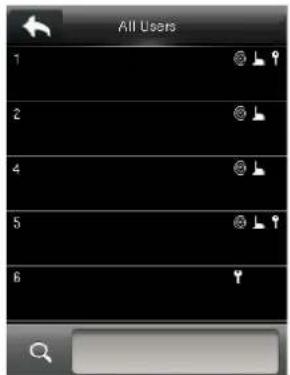
On the User Mgt. interface, click All Users to enter the All User interface (see Figure 2). Administrator may query, edit or delete users.
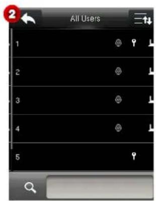
indicates that the current user is a super administrator.
indicates the user's fingerprint is enrolled ★.
☐: indicates that the user's badge number is enrolled ★.
♀: indicates that the user's password is enrolled.
: indicates that the user's finger vein is enrolled.
Tips: The information of all enrolled users is displayed according to the preset Display Style. For details about the Display Style, see 3.3 "Display Style."
3.2.1 Querying a User
You may query users by name or user ID. The detailed operation is as follows:
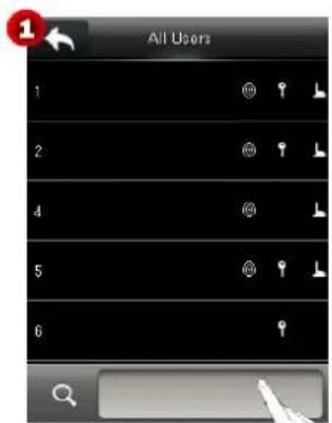
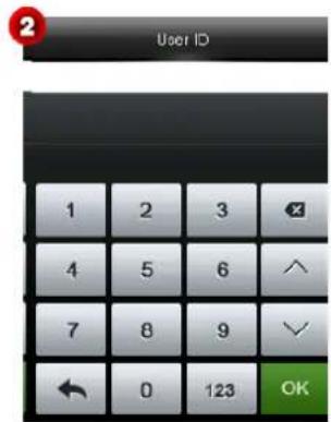
- Click the query box (see Figure 1) to enter the interface shown in Figure 2.
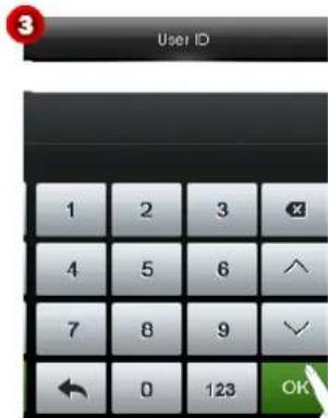
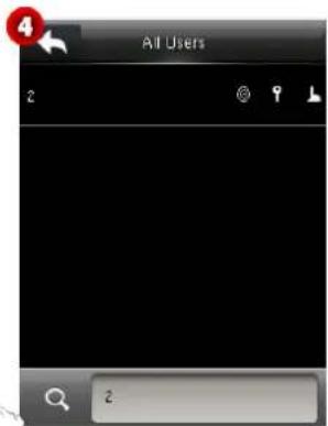
- Enter a query condition, click OK (see Figure 3) to return to the All Users interface. The information of the relevant user is displayed according to the query condition (see Figure 4).
3.2.2 Editing/Deleting a User
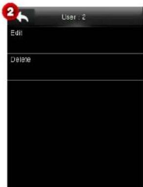
On All Users interface, click a user (see Figure 1) to enter the interface shown in Figure 2.
- Editing a user
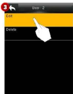
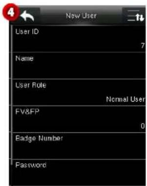
Click Edit (see Figure 3) to enter the New User interface (see Figure 4).
- Modify the user's information, and click ↩ to save settings and return to the previous interface.
Note: The method of editing a user is the same as that of adding a user and is not described here.
- Deleting a user
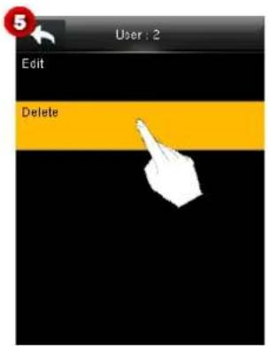
- Click Delete (Figure 5) to enter the interface as shown in Figure 6. Operation items are displayed according to the enrolled information.
Example: If a user's password is not enrolled, the item Delete Password Only is not displayed.
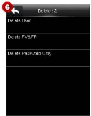
The following uses Delete Password Only as an example. The operation is described as below.
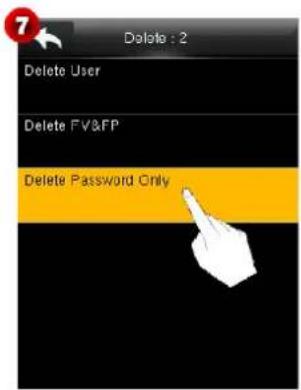
- Click Delete Password Only (see Figure 7), and a dialog box (see Figure 8) is displayed.
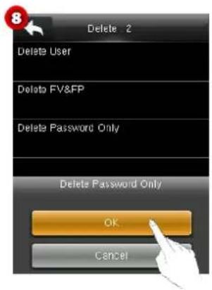
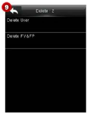
- Click OK to delete all the Passwords, or click Cancel to cancel the operation.
Notes:
(1) When deleting a user, the device delete all information of the user, including the finger vein, fingerprint ★, password, and badge number ★.
(2) When deleting a user role only, the device changes the user's role to Normal User.
(3) After the role of last super administrator is deleted, all user-defined roles becomes unavailable.
3.3 Display Style
- On the User Mgt. interface, click Display Style to enter the Display Style interface shown in Figure 2.
Tips: The default display style is Single Line.
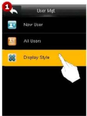
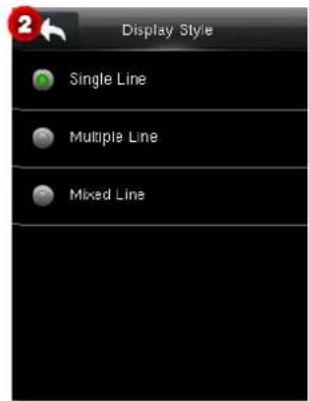
- On the Display Style interface, you may select Single Line, Multiple Line or Mixed Line for the display of user information.
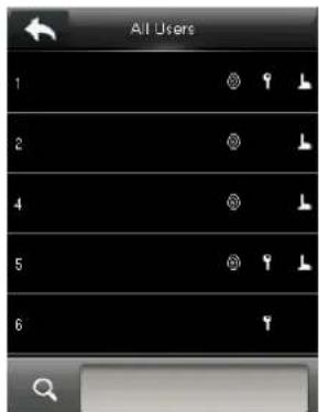
Single Line style
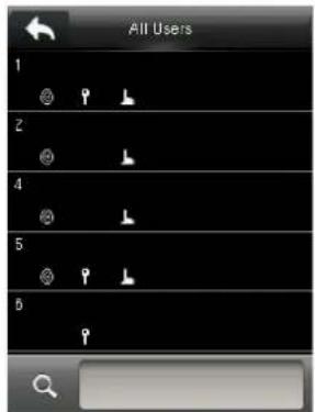
Multiple Line style
Mixed Line style
4 User Role
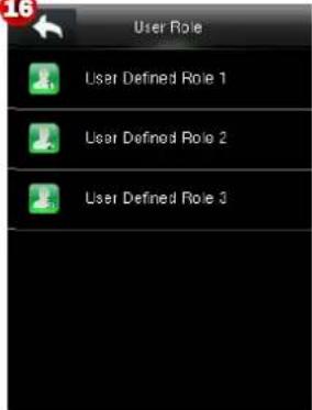
You can set user defined roles and assign operation levels to roles in User Role.
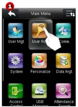
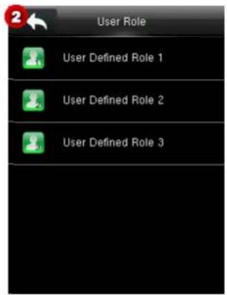
The user defined roles are set as follows:
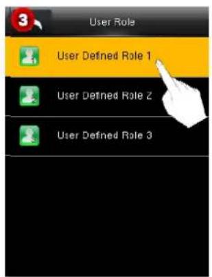
In the User Role list, select a role to be edited (see Figure 3) to enter the User Defined Role interface (see Figure 4).
Note: User defined roles can be set only after a super administrator is added. Otherwise, the dialog box shown in Figure 5 is displayed.
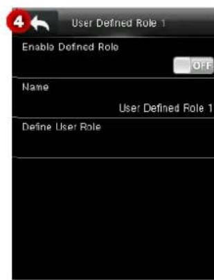
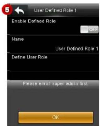
- Enable Defined Role
The default value is OFF, indicating that the role is disabled. Click and drag the icon to switch between ON and OFF. The ON icon means the role is enabled.
Name
Set a name for the role. Click Name to enter the Name interface (see Figure 7). Enter a name using the T9 input method, and click OK (see Figure 8) to save the settings and return to the previous interface (see Figure 9).
For detailed about how to enter a name, see Appendix 1 Text Input Operation Instructions
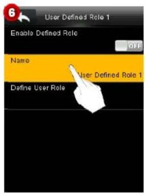
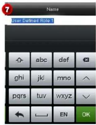
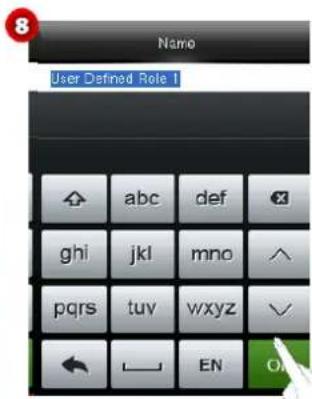
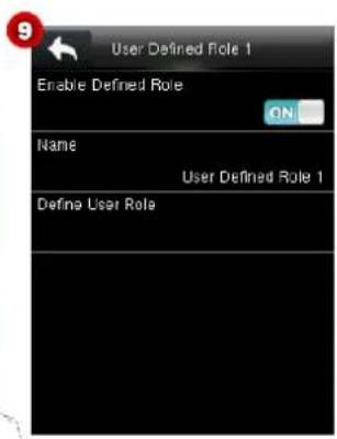
- Define User Role
To assign operation level to a role, do as follows:
- Click Define User Role to enter the interface shown in Figure 11, and click 📋 to scroll down the screen to display more content.
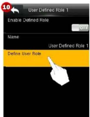
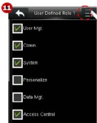
- Assign operation levels to the role (the symbol ☑ indicates the item is selected).

Tips: Click a parent level (see Figure 12) to enter an interface of child level selection (see Figure 13).
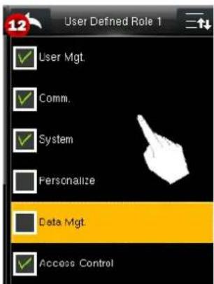
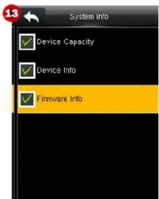
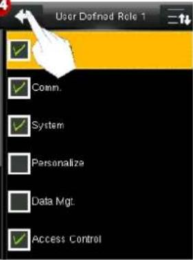
- After setting, click 📋 (see Figure 14) to save the settings and return to the User Defined Role Interface.
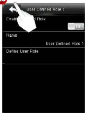
- On the User Defined Role interface, click 📄 (see Figure 15) to save the settings and return to the User Role interface.
14
15
16
5 Comm. Settings
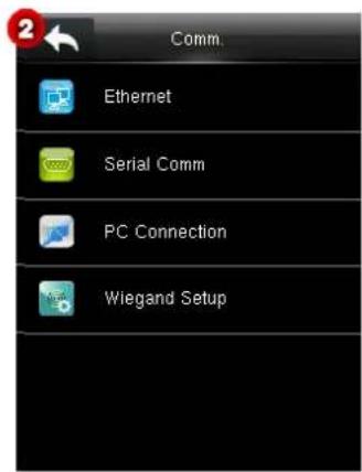
Set the parameters for the communication between the device and a PC, including the IP address, gateway, subnet mask, baud rate, device number, and connection password.
5.1 Ethernet Settings
On the Comm. Interface, click Ethernet to enter the Ethernet interface, and click 📄 to scroll down the screen to display more content. (Note: You can click 📄 again to scroll up the screen.)
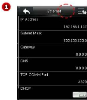
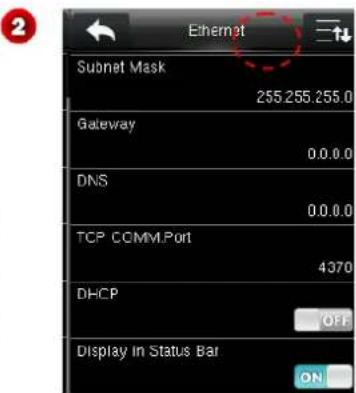
The parameters below are the factory default values, please adjust them according to the actual network situation.
IP Address: 192.168.1.201
Subnet Mask: 255.255.255.0
Gateway: 0.0.0.0
DNS: 0.0.0.0
TCP COMM. Port: 4370
DHCP: Dynamic Host Configuration Protocol, which is to dynamically allocate IP addresses for clients via server.
Display in Status Bar: To set whether to display the network icon on the status bar.
5.2 Serial Comm. Settings
Click Serial Comm to enter the Serial Comm interface.
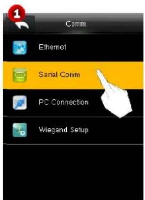
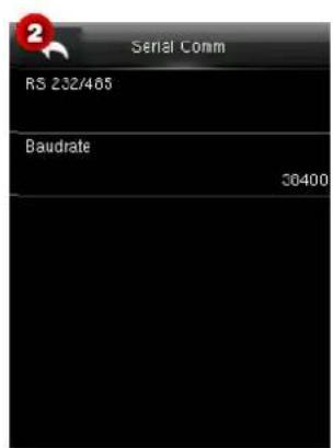
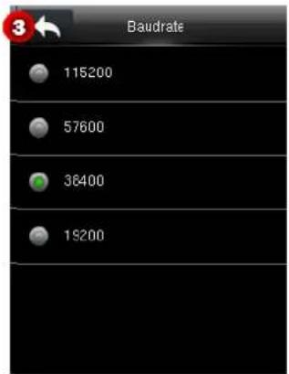
When the device communicates with a PC in serial mode, check the following settings.
RS232/485: Whether to enable RS485 for communication. The default value is ON. You can click RS485 to switch between OFF and ON.
Baudrate: The rate of the communication with PC; there are 5 options of baud rate: 115200 (default), 57600, 38400 and 19200. The higher is the baud rate, the faster is the communication speed, but also the less reliable. In general, a higher baud rate can be used when the communication distance is short; when the communication distance is long, choosing a lower baud rate would be more reliable.
5.3 PC Connection
To improve security of data, Comm Key for communication between the device and PC needs to be set. If a Comm Key is set in the device, the correct connection password needs to be entered when the device is connected to the PC software, so that the device and software can communicate.
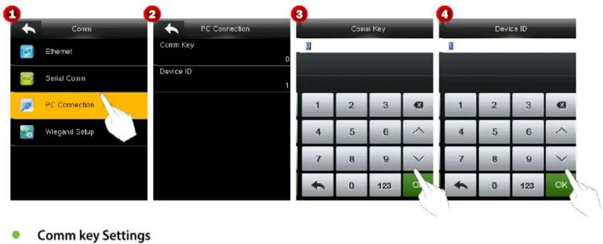
Comm Key: The default password is 0 (no password). Enter the Comm Key interface, enter the password, click OK (Figure 3) to save the settings and return to the PC Connection interface.

Note: Comm Key can be 1-6 digits and ranges from 0-999999.
Device ID Settings
Set the device ID. The default value is 1. Click Device ID to enter the Device ID interface, enter the ID, and click OK (see Figure 4) to save the settings and return to the PC Connection interface.

Note: The identity number of the device ranges from 1 to 254. For RS235 serial communication, the identity number of the device needs to be entered on the software communication interface.
5.4 Wiegand Setup
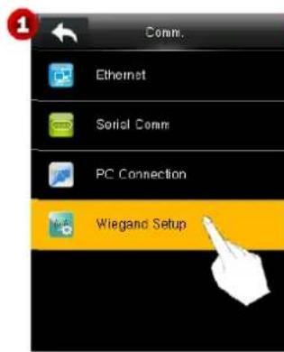
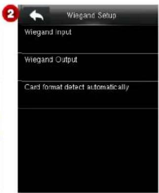
5.4.1 Wiegand Input
Set the Wiegand format of an externally connected reader.
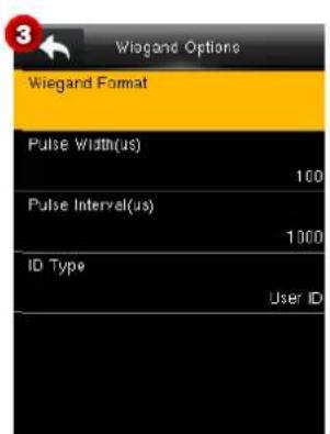
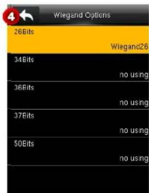
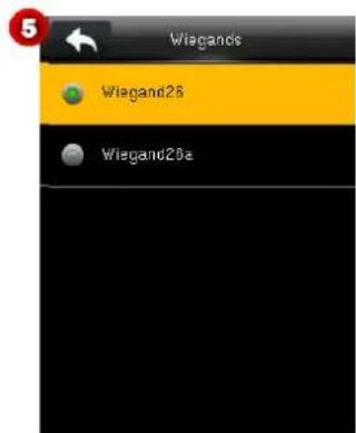
Wiegand Format: User can choose among the following built-in Wiegand formats: Wiegand 26, Wiegand 26a, Wiegand 34, Wiegand 34a, Wiegand 36, Wiegand 36a, Wiegand 37, Wiegand 37a, Wiegand 50 and.
No using. The value no using means that the format with this bit number is not used. The following table describes all the formats.
Pulse Width (us): The width of pulse sent by Wiegand. The default value is 100 microseconds, which can be adjusted within the range of 20 to 100 microseconds.
Pulse Interval (us): The default value is 1000 microseconds, which can be adjusted within the range of 200 to 20000 microseconds.
ID Type: Input content included in Wiegand input signal. User ID or Badge Number can be chosen.
Definitions of Wiegand Formats:
| Wiegand Format | Definition |
| Wiegand26 | ECCCCCCCCCCCCCCCCCCCCCCCOCO Consists of 26 bits of binary code. The 1^st bit is the even parity bit of the 2^nd to 13^th bits, while the 26^th bit is the odd parity bit of the 14^th to 25^th bits. The 2^nd to 25^th bits are the card number. |
| Wiegand26a | ESSSSSSSCCCCCCCCCCCCCCCO Consists of 26 bits of binary code. The 1^st bit is the even parity bit of the 2^nd to 13^th bits, while the 26^th bit is the odd parity bit of the 14^th to 25^th bits. The 2^nd to 9^th bits are the site code, while the 10^th to 25^th bits are the card number. |
| Wiegand34 | ECCCCCCCCCCCCCCCCCCCCCCCCCCCCCOCO Consists of 34 bits of binary code. The 1^st bit is the even parity bit of the 2^nd to 17^th bits, while the 34^th bit is the odd parity bit of the 18^th to 33^rd bits. The 2^nd to 25^th bits are the card number. |
| Wiegand34a | ESSSSSSSCCCCCCCCCCCCCCCCCCCCCO Consists of 34 bits of binary code. The 1^st bit is the even parity bit of the 2^nd to 17^th bits, while the 34^th bit is the odd parity bit of the 18^th to 33^rd bits. The 2^nd to 9^th bits are the site code, while the 10^th to 25^th bits are the card number. |
| Wiegand36 | OFFFFFFFFFFFFFCCCCCCCCCCCCCMME Consists of 36 bits of binary code. The 1^st bit is the odd parity bit of the 2^nd to 18^th bits, while the 36^th bit is the even parity bit of the 19^th to 35^th bits. The 2^nd to 17^th bits are the device code, the 18^th to 33^rd bits are the card number, and the 34^th to 35^th bits are the manufacturer code. |
| Wiegand36a | EFFFFFFFFFFFFFCCCCCCCCCCCCCCCO Consists of 36 bits of binary code. The 1^st bit is the even parity bit of the 2^nd to 18^th bits, while the 36^th bit is the odd parity bit of the 19^th to 35^th bits. The 2^nd to 19^th bits are the device code, and the 20^th to 35^th bits are the card number. |
| Wiegand37 | OMMMMSSSSSSSSSSCCCCCCCCCCCCCCCCE Consists of 37 bits of binary code. The 1^st bit is the odd parity bit of the 2^nd to 18^th bits, while the 37^th bit is the even parity bit of the 19^th to 36^th bits. The 2^nd to 4^th bits are the manufacturer code, the 5^th to 16^th bits are the site code, and the 21^st to 36^th bits are the card number. |
| Wiegand37a | EMMMFFFFFFFFFFFFSSSSSSCCCCCCCCCCCCCO Consists of 37 bits of binary code. The 1^st bit is the even parity bit of the 2^nd to 18^th bits, while the 37^th bit is the odd parity bit of the 19^th to 35^th bits. The 2^nd to 4^th bitsare the manufacturer code, 5^th to 14^th bits are the device code, 15^th to 20^th bits are the site code, and the 21^st to 36^th bits are the card number. |
| Wiegand50 | ESSSSSSSSSSSSSSCCCCCCCCCCCCCCCCCCCCCCCCCCCCC CONSists of 50 bits of binary code. The 1^st bit is the even parity bit of the 2^nd to 25^th bits, while the 50^th bit is the odd parity bit of the 26^th to 49^th bits. The 2^nd to 17^th bits are the site code, and 18^th to 49^th bits are the card number. |
Note: C denotes card number, E denotes even parity bit, O denotes odd parity bit, F denotes device code, M denotes manufacturer code, P denotes parity bit, and S denotes site code.
5.4.2 Wiegand Output
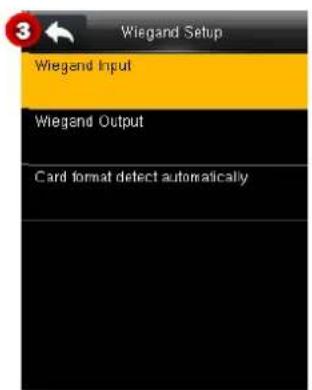
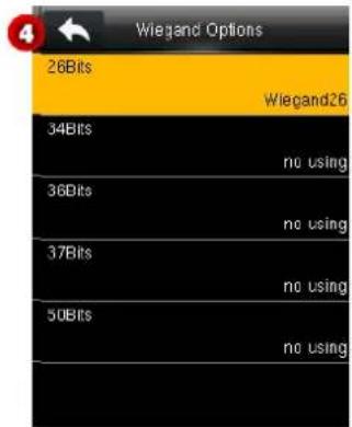
Wiegand format: Users can select the standard Wiegand formats built in the system. See the definitions of all types of general Wiegand formats in 5.4.1 "Wiegand Input." Multiple choices are supported, but the actual format is determined by Wiegand output bits.
Wiegand output bits: Number of bits of Wiegand data. After choosing [Wiegand output bits], the device will use the set number of bits to find the suitable Wiegand format in [Wiegand Format].
For example, if 26-bit Wiegand26, 34-bit Wiegand34a, 36-bit Wiegand36, 37-bit Wiegand37a and 50-bit Wiegand50 are selected but the Wiegand output bits is set to 36, the 36-bit Wiegand36 format is adopted.
Failed ID: It is defined as the output value of failed user verification. The output format depends on the [Wiegand Format] setting. The default value ranges from 0 to 65535.
Site Code: It is similar to device ID except that it can be set manually and repeatable with different devices. The default value ranges from 0 to 256.
Pulse Width (us): The width of pulse sent by Wiegand. The default value is 100 microseconds, which can be adjusted within the range of 20 to 100 microseconds.
Pulse Interval (us): The default value is 1000 microseconds, which can be adjusted within the range of 200 to 20000 microseconds.
ID Type: Output content after successful verification. User ID or card number can be chosen.
5.4.3 Card Format Detect Automatically
[Card Format Detect Automatically] aims at assisting user with quickly detecting the card type and its corresponding format. Various card formats are preset in the device. After card swiping, the system will detect it as different card numbers according to every format; user only requires choosing the item equivalent to the actual card number, and sets the format as the Wiegand format for the device. This function is also applicable to card reading function and auxiliary Wiegand reader.
Card number obtained based on the IntWiegnad26 format parsing
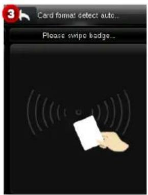
After entering automatic detection, swipe the badge in badge swiping area (on this device or reader).
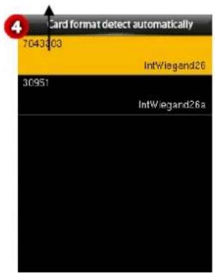
The Wiegand format and parsed card number are automatically detected.
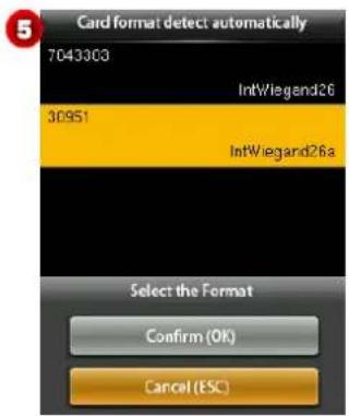
Select the number consistent with the actual card number, and the corresponding format is the Wiegand format which should be selected for reading this type of card.
6 System Settings
Set system parameters, including date and time, access logs★, finger vein parameters, factory settings restoration, and USB disk upgrade, so that the device meets user requirements to the maximum extent in functions and display.
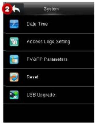
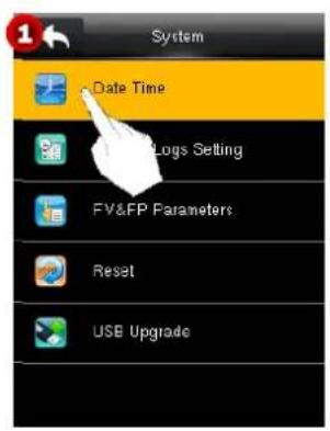
6.1 Date/Time Settings
Set the date and time of the device.
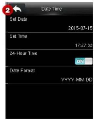
Date and Time: Set the date and time of the device.
24-Hour Time: Set a display format of time on the main interface. Select ON so that the time is displayed in 24-hour system, or select OFF so that the time is displayed in 12-hour system.
Date Format Set the format of time displayed on all interfaces of the device.
6.2 Access Logs Setting★
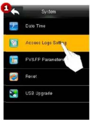
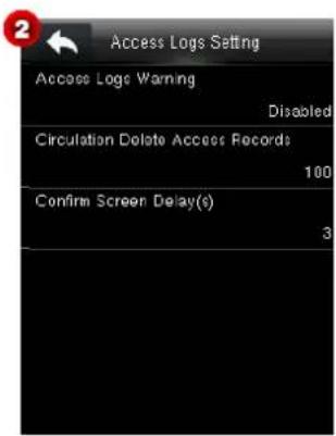
Access Logs Warning: When the residual record capacity is smaller than the preset value, the device automatically generates a message indicating residual record capacity. You can set it to Disabled or set to a value ranging from 1 to 9999.
Circulation Delete Access Records: Set the number of log entries that can be deleted at a time when existing records reach the allowed maximum log capacity The default value is Disabled. You can set it to a value ranging from 1 to 999.
Confirm Screen Delay(s): Set the duration to display messages of verification results. The valid value range is 1-9.
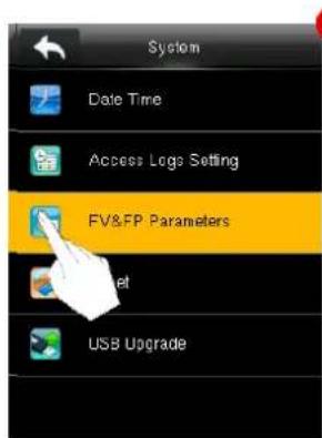
6.3 FV&FP Parameter Setting★
1
2
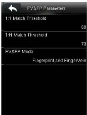
1:1 Match Threshold: Set the similarity between the finger vein image collected currently and the enrolled images in the device in 1:1 verification mode. The default value is 60, and you can set it to a value ranging from 55 to 75. When the similarity reaches the set level, the verification is passed. The higher the threshold is, the lower the misjudgment rate is and the higher the false rejection rate is, and vice versa.
1:1 Match Threshold: Set the similarity between the finger vein image collected currently and the enrolled images in the device in 1:N verification mode. The default value is 70, and you can set it to a value ranging from 65 to 85.
When the similarity reaches the set level, the verification is passed. The higher the threshold is, the lower the misjudgment rate is and the higher the false rejection rate is, and vice versa.
Recommended match thresholds:
| False Rejection Rate | Misjudgment Rate | Match Threshold | |
| 1:N | 1:1 | ||
| High | Low | 85 | 75 |
| Medium | Medium | 70 | 60 |
| Low | High | 65 | 55 |
FV&FP Mode: Verification is passed when both a finger vein verification and a fingerprint verification are passed.
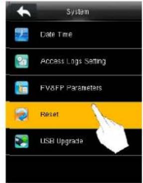
6.4 Reset to Factory Settings
Reset data such as communication settings and system settings to factory settings.
1
2
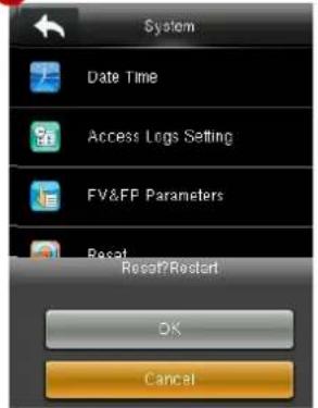
Note: After reset, the user information in the device and the settings on the access control interface are not deleted.
6.5 USB Upgrade
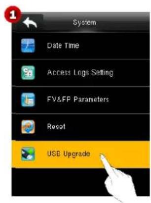
This function enables the device firmware to be upgraded with an upgrade file in a USB disk.
Insert a USB disk into the USB port, and click USB Upgrade to upgrade the firmware.
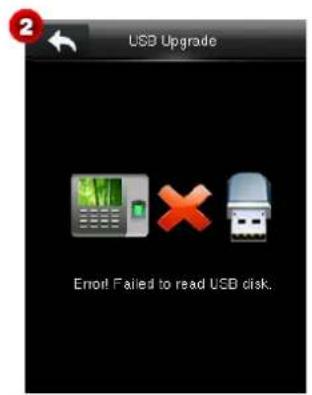
Notes:
(1) If no USB disk is inserted, a message as shown in Figure 2 is displayed.
(2) If an upgrade file is needed, please contact out technical support. Firmware upgrade is not recommended under normal circumstances.
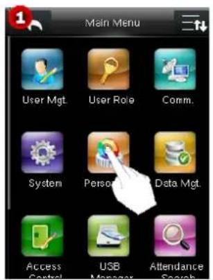
7 Personalize Settings
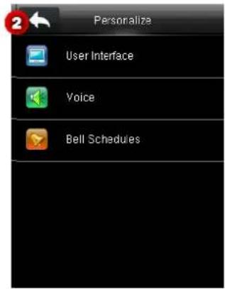
7.1 User Interface Settings
You may customize the display style of the home interface.
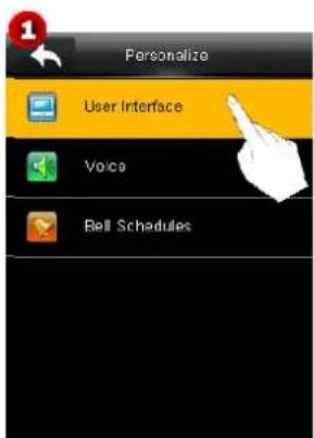
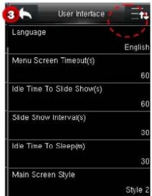
On the Personalize Interface, click User Interface to enter an interface, and click 📄 to scroll down the screen to display more content. (Note: You can click 📄 again to scroll up the screen.)
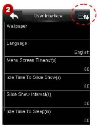
- Wallpaper
Select the wallpaper of main screen as required, you can find wallpapers of various styles in the device. The detailed operation is as follows:
- Click Wallpaper.
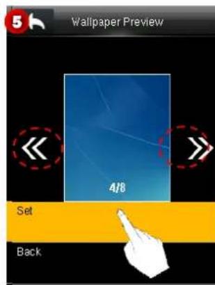
- Click an image (Figure 4) to enter the Wallpaper Preview interface.
- Eight wallpapers are stored in the device. To select one, click <<>> and then click Set (Figure 5). After setting, the device returns to the Wallpaper interface.
Click (Figure 6) to save the setting and return to the User Interface interface.


• Language: Select the language of device as required.
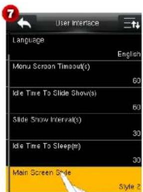
- Menu Screen Timeout (s)
When there is no operation in the menu interface and the time exceeds the set value, the device will automatically exit to the initial interface. You can disable it or set the value to 60\~99999 seconds.
● Idle Time To Slide Show (s)
When there is no operation in the initial interface and the time exceeds the set value, a slide show will be shown. It can be disabled (set to "None") or set to 3\~999 seconds.
- Slide Show Interval (s)
This refers to the interval between displaying different slide show pictures. It can be disabled or set to 3\~999 s.
- Idle Time To Sleep (m)
When there is no operation in the device and the set Sleep Time is attained, the device will enter standby mode. Press any key or finger to cancel standby mode. You can disable this function, or set the value to 1\~999 minutes. If this function is turned to [Disabled], the device will not enter standby mode.
- Main Screen Style
The detailed operation is as follows:
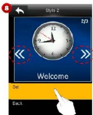
- Click Main Screen Style to enter the setting interface.
- Click 🔊 to switch and select a style, and then click Set (Figure 8). After setting, the device returns to the Wallpaper interface.
7.2 Voice Settings
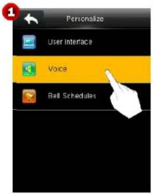
Click Voice to enter the setting interface.
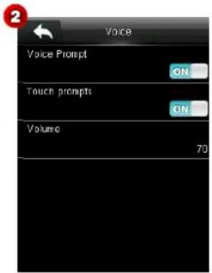
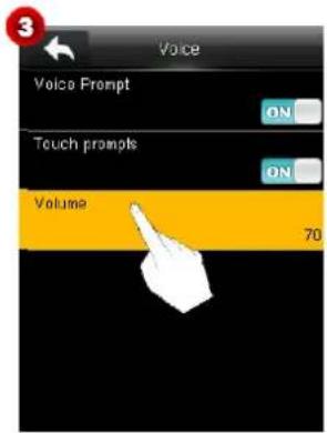
Voice Prompt Select whether to enable voice prompts during operating. The default value is ON, indicating that voice prompt is enabled. You may click it to switch between ON and OFF. The icon OFF indicates that voice prompt is disabled.
Keyboard Prompt: Select whether to enable keyboard voice while pressing keyboard. The default value is ON, indicating that keyboard prompt is enabled. You may click it to switch between ON and OFF. The icon OFF, indicating that keyboard prompt is disabled.
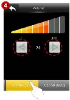
Volume: Set the volume of device. The default value is 70. Click Volume to enter the setting interface. Click to turn down/up the volume, then click Confirm (OK) (see Figure 4) to save and return to the Voice interface.
7.3 Bells Settings
Many companies choose to use bells to signify on-duty and off-duty time. When reaching the scheduled time for bell, the device will play the selected ringtone automatically until the ringing duration is passed.
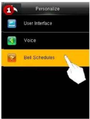
Click Bell Schedules to enter the Bell Schedules interface.
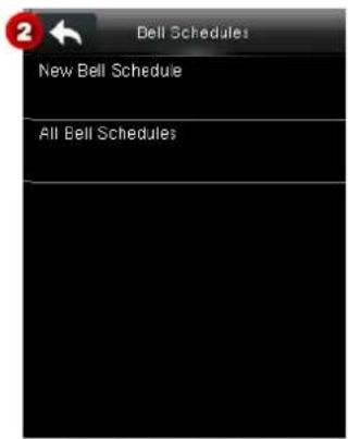
7.3.1 New Bell Schedule
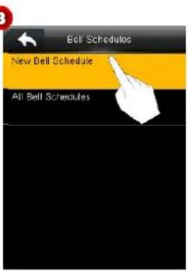
- Click New Bell Schedule to enter the New Bell Schedule interface (see Figure 4).
3
4
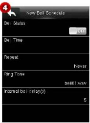
- You may set the parameters as needed. The detailed operation is as follows:
Bell Status
The default value is OFF, indicating that bell status is disabled. Click it to switch between ON and OFF. The icon ON indicates bell status is enabled.
Notes: The schedule is effective only after the bell status is set to ON.
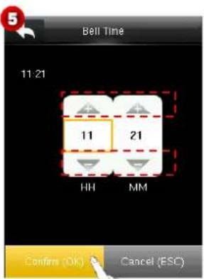
Bell Time
Set the start time for a bell.
Click Bell Time to enter the Bell Time interface.
(2) Set the bell time by clicking ▲/▼ to increase/decrease numbers, and click Confirm (OK) (see Figure 6) to save and return to the New Bell Schedule interface.
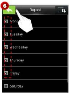
- Repeat
The default value is Never, which is used for a one-time bell schedule.
To repeat using a bell schedule, click Repeat to enter the Repeat interface. Tick one or multiple dates requiring a bell schedule, and click (see Figure 6) to save the settings and return to the New Bell Schedule interface. When the selected dates and bell time come, relay signals are triggered and the set bell is played. When the bell duration is up, the bell stops automatically.
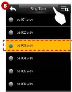
Ring Tone
Set a ring tone for the bell schedule.
Click Ring Tone to enter the Ring Tone interface.
(2) In the ring tone list, click a ring tone to select it, and click 📊 (see Figure 8) to save the settings and return to the New Bell Schedule interface.
- Internal Bell Delay(s)
Set the bell delay. The default value is 5 seconds. You may set it to a value ranging from 1 to 999.
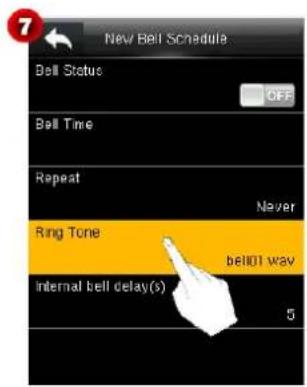
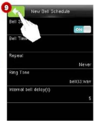
- After setting, click in the New Bell Schedule interface (Figure 9) to save the settings and return to the previous interface.
7.3.2 All Bell Schedules
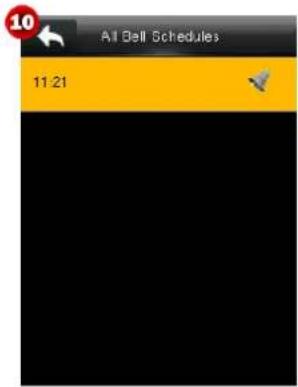
In the Bell Schedules interface, click All Bell Schedules to enter the interface as shown in Figure 10. You may edit/delete bell schedules as needed.
Note: The method of editing/deleting bell schedules is the same with that of editing/deleting users. For details, see 3.2.2 Editing/Deleting a User.
8 Data Mgt.
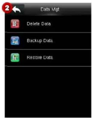
In the Main Menu interface, click Data Mgt. to enter the Data Mgt. interface.
8.1 Delete Data
Manage data in the device, which includes deleting attendance data, deleting all data, deleting admin role and deleting screen savers etc.
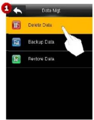
Click Delete Data to enter the Delete Data interface, and click 📄 to scroll down the screen to display more content. (Note: You can click 📄 again to scroll up the screen.)
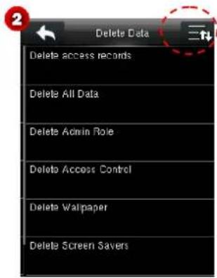
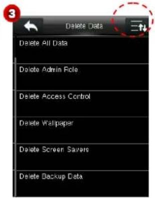
- ★Delete Access Records : Delete all the access records.
- Delete All Data: Delete all user information, finger vein information and attendance logs, etc.
- Delete Admin Role: Make all Administrators become Normal Users.
- Delete Access Control: Restore the access control settings, such as holidays, user permissions, time rules, user groups, to the factory default settings. The access records will not be deleted.
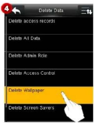
- Delete Wallpaper
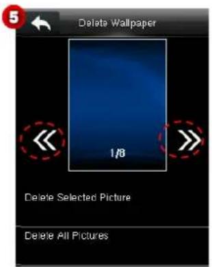
Delete wallpapers. The specific operations are as follows.
-
Click Delete Wallpaper.
-
Click 🔊 to switch and select a wallpaper, and then click Delete Selected Picture to delete the selected picture or click Delete All Pictures to delete all pictures.
- Delete Screen Savers
The method of deleting screen savers is the same as that of deleting wallpapers. (For details about how to upload screen savers, see 10.2 USB Upload.)
- Delete Backup Data: Delete all backup data.
8.2 Backup Data
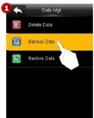
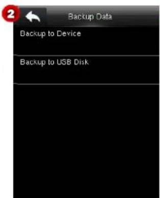
- Backup to Device
You may back up the business data or configuration data in the device to the local PC.
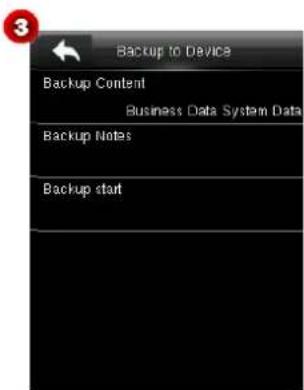
- Click Backup to Device to enter the Backup to Device interface.
- You may set the parameters as needed. The detailed operation is as follows:
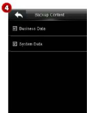
Backup Content Click Backup Content to enter the Backup Content interface. Select content to be backed up. (Note: The icon ☑ indicates a chosen item.)
Backup Notes: Enter backup content. The detailed method is as follows:
Click Backup Notes to enter the Backup Notes interface (see Figure 5).
② Click on the screen. A keyboard is prompted. Enter note using the T9 input method, and then click OK (see Figure 6) to confirm and return to the Backup Notes interface.
③ Click Confirm (OK) (see Figure 7) to save the settings and return to the Backup to Device interface.
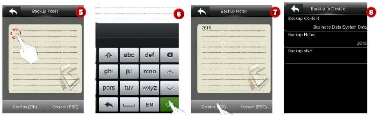
- After setting, click Backup Start to start backing up content to the device.
- Backup to USB Disk
Back up the business data or configuration data in the device to a USB disk. The method is the same as that used in Backup to Device.
Notes:
(1) Before backing up data to a USB disk, please insert a USB disk into the USB port of the device.
(2) Before backing up data to a local PC, the system replaces the old backup data with the most updated one.
8.3 Restore Data
On the Data Mgt. interface, click Restore Data to enter the Restore Data interface.
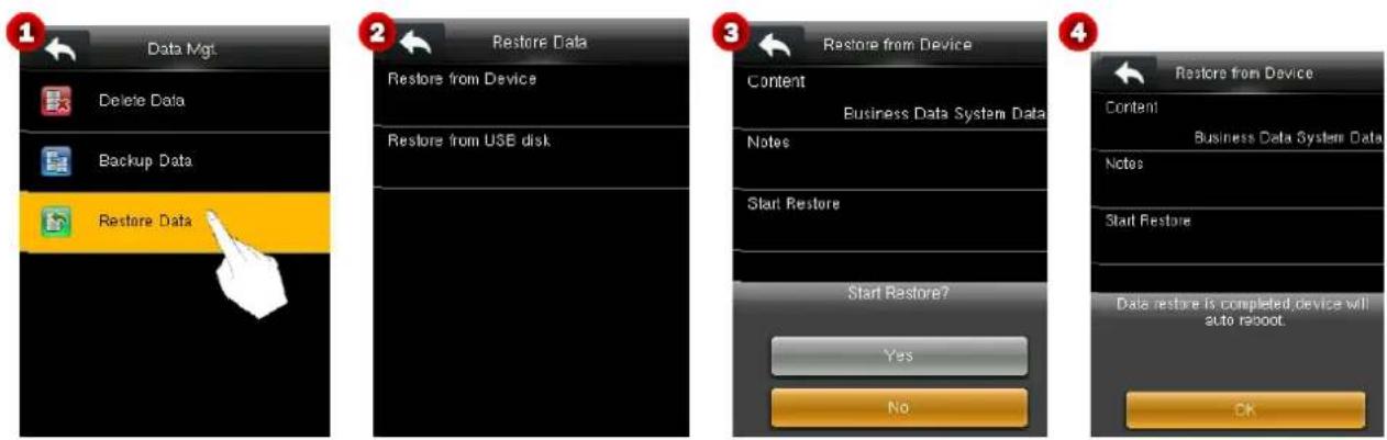
- Restore from Device
Restore the data in the device from the local PC.
-
Click Restore from Device to enter the Restore from Device interface.
-
Click Start Restore, and a dialog (see Figure 3) is prompted. Click Yes to start.

Note: After restoration, click OK to restart the device.
- Restore from USB Disk
Restore the data in the device from a USB disk. The detailed operation is the same as that used in Restore from Device.

Note: Before restoring data from a USB disk, insert the USB disk carrying backup data into the USB port of the
device.
9 Access Control
The settings of access control function are for the users' access periods and the parameters of the control lock and related device.
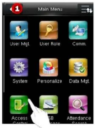
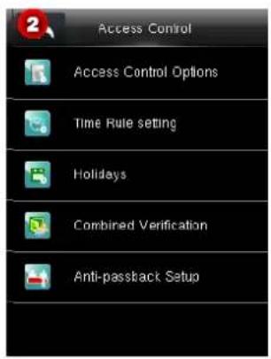
To gain access, the registered user must meet the following conditions:
- User's access time falls within either user's personal time zone or group time zone.
- User's group must be in the access combo (when there are other groups in the same access combo, verification of members of those groups are also required to unlock the door).
In default settings, new users are allocated into the first group with the default group time zone and access combo as "1", and set in unlocking state.
9.1 Access Control Options Settings
In the Access Control interface, click Access Control Options to enter the Access Control Options interface, and click 📄 to scroll down the screen to display more content. (Note: You can click 📄 again to scroll up.)
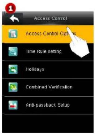
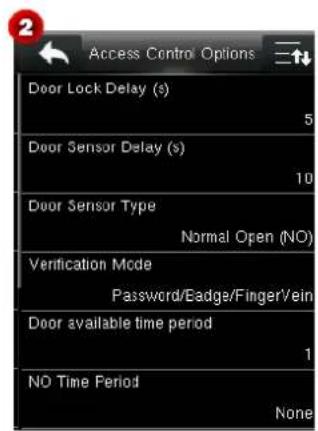
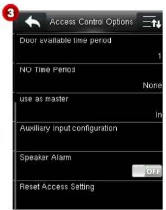
Set the parameters of the control lock and related devices.
Door Lock Delay (s): The period of time of unlocking (from door opening to closing automatically) after the electronic lock receives an open signal sent from the device (value ranges from 0 to 10 seconds).
Door Sensor Delay (s): When the door is opened, the door sensor will be checked after a time period; if the state of the door sensor is inconsistent with that of the door sensor mode, alarm will be triggered. The time period is the Door Sensor Delay (value ranges from 0 to 255 seconds).
Door Sensor Type: It includes No, Normally Open and Normally Closed. No means door sensor is not in use; Normally Open means the door is opened when electricity is on; Normally Closed means the door is closed when electricity is on.
Verification Mode: You may select Password/Finger Vein, Badge Only, Password, Finger Vein, Password & Finger Vein, Badge/Fingerprint ★, Fingerprint Only , Badge Only , Fingerprint & Password , Badge & Password ★, Badge & Fingerprint or Badge & Fingerprint & Password as needed.
Door Available Time Period: Set periods to open the door for users.
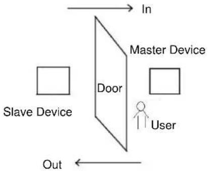
Use as master. While configuring the master and slave devices, you may set the state of the master as Out or In.
Out: A record of verification on the master device is a check-out record.
In: A record of verification on the master device is a check-in record.
Auxiliary Input Configuration: Set the Aux output/lock open time and Aux Output type for the device with auxiliary connector. Aux Output type includes None, trigger door open, trigger Alarm, and trigger Door open and Alarm.
Speaker Alarm: When the [Speaker Alarm] is enabled, the speaker will raise an alarm when the device is being dismantled.
Reset Access Setting: Reset parameters of door lock delay, door sensor delay, door sensor type, door alarm delay, retry times to alarm, NO time period, auxiliary input configuration, excluding the access data to be deleted in Data Mgt.
| Access Parameters | Factory Default |
| Door Lock Delay | 10s |
| Door Sensor Delay | 10s |
| Door Sensor Mode | No |
| Door Alarm Delay | 30s |
| NO Time Zone | No |
| Auxiliary Output Access Time★ | 255s |
Remarks: After setting NC Time Period, please lock the door well, otherwise alarm might be triggered during NC Time Period.
9.2 Time Schedule Settings
Time Schedule is the minimum time unit of access control settings; at most 50 Time Schedules can be set for the system. Each Time Schedule consists of 7 time sections (a week), and each time section is the valid time within 24 hrs.
You may set a maximum of 3 periods for every time rule. The relationship among these periods is "or". When the verification time falls in any one of these periods, the verification is valid. The period format is HH:MM-HH:MM in the 24-hour system with precision to seconds.
On the Access Control interface, click Time Rule Setting to enter the Time Rule interface, and click ☑ to scroll down the screen to display more content. (Note: You can click ☑ again to scroll up the screen.)

![Time Rule [02:50] Sunday [30:00 23:59] [00:00 23:59] [00:00 23:59] Monday [30:00 23:59] [00:00 23:59] [00:00 23:59] Tuesday [30:00 23:59] [00:00 23:59] [00:00 23:59] Wednesday [30:00 23:59] [00:00 23:59] [00:00 23:59] Thursday [30:00 23:59] [00:00 23:59] [00:00 23:59]](/content/2026/05/979491/images/5a4a1ff8e8a3fc2c5c5e01abf9b27232517985006ed65e2fad184171a00022c0.jpg)
![Time Rule [02/50] Friday [00:00 23:59] [00:00 23:59] [00:00 23:59] Saturday [00:00 23:59] [00:00 23:59] [00:00 23:59] holiday type 1 [00:00 23:59] [00:00 23:59] [00:00 23:59] holiday type 2 [00:00 23:59] [00:00 23:59] [00:00 23:59] holiday type 3 [00:00 23:59] [00:00 23:59] [00:00 23:59]](/content/2026/05/979491/images/6eea3631fbe6e3a7b18d625b6ce05cf0d583812f6f8fb5b42a741124d8284e52.jpg)
- Editing a Time Rule
A super administrator may edit time rules as needed. The detailed operation is as follows:
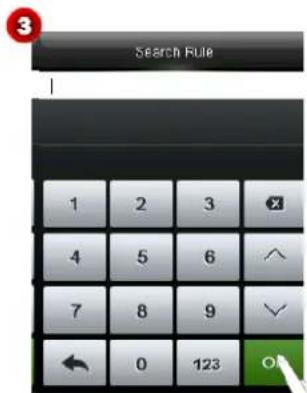
- Click the query box (see Figure 2) to enter the Search Rule interface.
- Enter a time rule number, click OK (see Figure 3) to enter the Time Rule interface (see Figure 4).
- In the time period list, click a period to be edited (see Figure 5) to enter the Time Schedule interface (see Figure 6).
![Time Rule [02/50] Friday [00:00 23:59] [00:00 23:59] [00:00 23:59] Saturday [00:00 23:59] [00:00 23:59] [00:00 23:59] holiday type 1 [00:00 23:59] [00:00 23:59] [00:00 23:59] holiday type 2 [00:00 23:59] [00:00 23:59] [00:00 23:59] holiday type 3 [00:00 23:59] [00:00 23:59] [00:00 23:59]](/content/2026/05/979491/images/f2f6ef3b5818245e629b53ac1355862ee84e6da20996783695c25628c3866938.jpg)
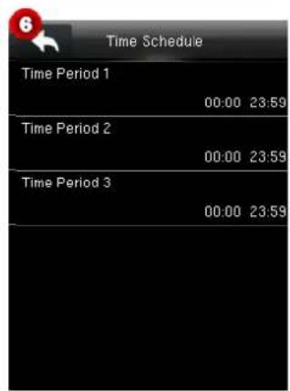
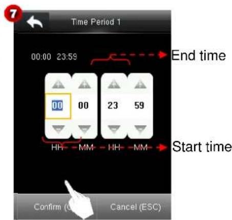
- In the listed time schedules, click Time Period 1/2/3 to enter the setting interface. You may set the start time and end time of a period as needed.

Tips: Click the icon 📄/ to increase/decrease numbers while setting time.
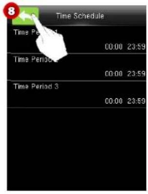
- After setting, click Confirm (OK) (see Figure 7) to save the settings and return to the Time Schedule interface, and click 📄 (see Figure 8) to save the settings and return to the Time Rule interface.
![Time Rule [02/50] Sunday [00:00 23:59] [00:00 23:59] Monday [00:00 23:59] [00:00 23:59] Tuesday [00:00 23:59] [00:00 23:59] Wednesday [00:00 23:59] [00:00 23:59] Thursday [00:00 23:59] [00:00 23:59]](/content/2026/05/979491/images/ab124ae9313465622d4ed38ae5b3afce806967ebd95412d4cc22fbfa5de40cd6.jpg)
- Set the other periods of the time rule. Click 📄 (see Figure 9) on the Time Rule interface to save the settings and return to the upper-level interface.
Notes:
(1) When the end time is earlier than the start time (for example, 23:57-23:56), this means closing all day long. When the end time is later than the start time (for example, 00:00-23:59), this means that this interval is valid.
(2) Valid Time Schedule: 00:00-23:59 (Whole-day valid) or when the end time is greater than the start time.
(3) By default, time rule numbered 1 indicates full-day opening.
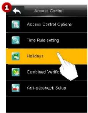
9.3 Holidays Settings
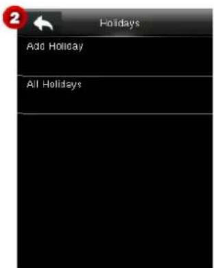
Add access control holidays for the device and set time periods on holidays as needed. The device controls the access control on holidays according to the holiday settings.
9.3.1 Add Holiday
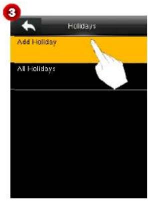
- Click Add Holiday to enter the Holidays interface (see Figure 4).
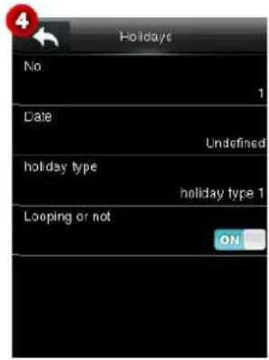
- Set holiday parameters as needed. The parameters are set as follows:
No.
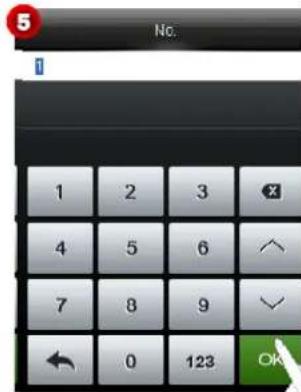
The device automatically assigns a number to a holiday. Click No. to enter the No. interface. Enter a holiday No. as needed and click OK (see Figure 5) to save the settings and return to the Holidays interface.
Note: A holiday No. ranges from 1 to 2000.
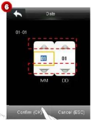
Date
Set the date of a holiday.
(1) Click Date to enter the Date interface.
(2) Click ▲ to increase a number upwards or click ▼ to decrease a number downwards to set the date. Then, click Confirm (OK) (see Figure 6) to save the settings and return to the Holidays interface.
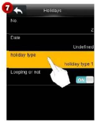
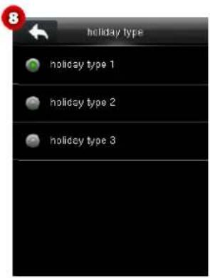
- holiday type
Set the type of a holiday.
(1) Click holiday type to enter the holiday type interface.
(2) Select a holiday type and click (see Figure 8) to save the settings and return to the Holidays interface.
- Looping or not
The default value of Looping or not is ON. You can click Looping or not to switch between ON and OFF.
For fixed holidays every year, for example, the New Year's Day is January 1, Looping or not can be set to ON for them. For unfixed holidays every year, for example, the Mother's Day is the second Sunday of May, the specific dates are uncertain and Looping or not can be set to OFF for them.
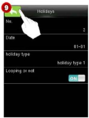
For example, when the date of a holiday is set to January 1, 2010 and holiday type is set to holiday type 1, the access control on January 1 is conducted according to the time period settings of holiday type 1 rather than the time period settings of Friday.
After setting, click 🏠 on the Holidays interface (see Figure 9) to save the settings and return to the upper-level interface.
9.3.2 Include Holidays
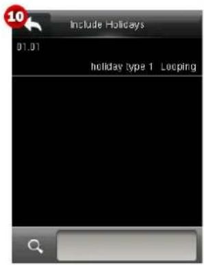
On the Holidays interface shown in Figure 3, click All Holidays to enter the Include Holidays interface (see Figure 10). You can edit or delete holidays as needed.
Note: The methods of editing or deleting a holiday are the same as those of editing or deleting a user and are not described here. For details, see 3.2.2 Editing/Deleting a User.
9.4 Combined Verification Settings
Notes:
(1) The Access3.5 software is not required if the device is used for the first time. You can set combined verification on the device directly.
(2) After combined verification is set on the Access3.5 software and the settings are delivered to the device, the device supports only the combined verification settings delivered from the Access3.5 software and combined verification cannot be set on the device.
Combine two or more members to achieve multi-verification and improve security.
In combined verification, the range of a user number is: 0 ≤ N ≤ 5 ; the users can all belong to a single group, or belong to 5 different groups at most.
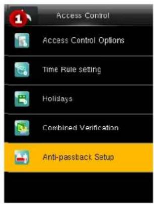
On the Access Control interface, click Combined Verification to enter the Combined Verification interface.
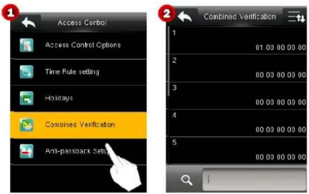
By default, the device supports ten unlocking combinations. Users can modify combined verification settings as needed. The specific operations are as follows:
For example, add an unlocking combination requiring simultaneous verification of user group 1 and user group 2.
-
On the Combined Verification interface, click a combination to be modified to enter the interface shown in Figure 3.
-
Click ▲ to increase a number upwards or click ▼ to decrease a number downwards to set the ID of a user group. Then, click Confirm (OK) to save the settings and return to the Combined Verification interface.
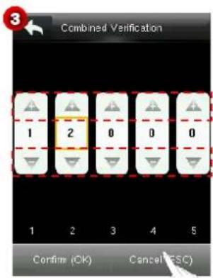
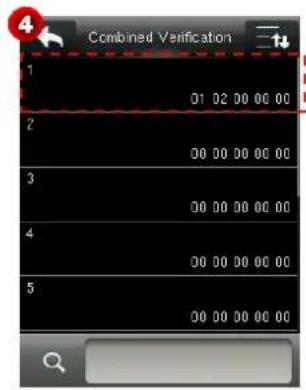
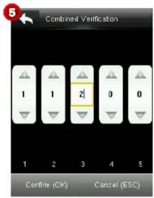
After the setting is successful, a door can be opened only after a user in user group 1 and a user in user group 2 pass the verification.
Notes:
(1) An unlocking combination supports a maximum of five user groups. That is, in an unlocking combination, a door can be opened only after a maximum of five users pass the verification.
(2) After an unlocking combination shown in Figure 5 is set, a door can be opened only after a user in user group 2 and two users in user group 1 pass the verification.
(3) An unlocking combination is cleared when the IDs of user groups in the unlocking combination are all set to 0.
9.5 Anti-passback Settings
To avoid some persons following users to enter the door without verification, resulting in security problem, users can enable anti-passback function. The check-in record must match with check-out record so as to open the door. This function requires two devices to work together: one is installed inside the door (master device) and the other one is installed outside the door (slave device). The two devices communicate via Wiegand signal. The Wiegand format and Output type (User ID / Badge Number) adopted by the master device and slave device must be consistent.
flowchart
graph TD
    A["Slave Device"] --> B["Door"]
    C["User"] --> B
    B --> D["In"]
    B --> E["Out"]
    style A fill:#fff,stroke:#000
    style C fill:#fff,stroke:#000
    style D fill:#fff,stroke:#000
    style E fill:#fff,stroke:#000
Anti-Passback Direction
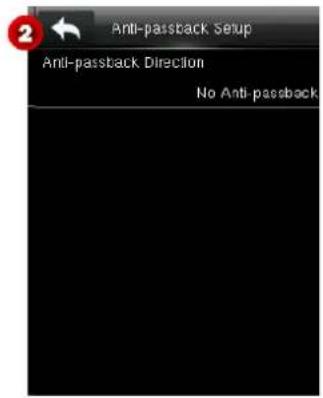
No Anti-passback: Anti-Passback function is disabled, which means passing verification of either master device or slave device can unlock the door. Attendance state is not reserved.
Out Anti-passback: After a user checks out, only if the last record is a check-in record can the user check out again; otherwise, the alarm will be triggered. However, the user can check in freely.
In Anti-passback: After a user checks in, only if the last record is a check-out record can the user check in again; otherwise, the alarm will be triggered. However, the user can check out freely.
In/Out Anti-passback: After a user checks in/out, only if the last record is a check-out record can the user check in again, or a check-in record can the user check out again; otherwise, the alarm will be triggered.
10 USB Manager
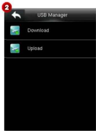
User information, finger vein templates, fingerprint templates, verification data, and other data can be exported to relevant software for processing through a USB disk, and user information, finger vein templates, and other data can be imported to the device by using a USB disk.

Remarks: Before uploading/downloading data from/to the USB disk, insert the USB disk into the USB slot first.
10.1 USB Download
Download access control records ★ and user data in the device to a USB disk.
Download access records ★: Store access control records in a specified date range in the device to a USB disk.
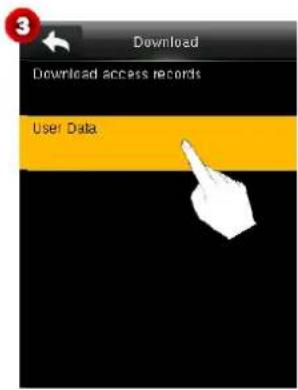
User Data: Download all user information and finger vein information from the device to a USB disk.
The following uses the operation of downloading user data as an example to describe how to download data by using a USB disk.
- Choose Download > User Data to start downloading user data to a USB disk. After the downloading is successful, "Download is done" is displayed on the screen (see Figure 4).
- Remove the USB disk and click ↩ to return to the Download interface.
![User Data Download is done. [DK] or [ESC] to exit.](/content/2026/05/979491/images/b543c52bb45730f28135706d7858370dbc782d2276b7867e77d7d94485627ded.jpg)
10.2 USB Upload
Upload use data, screen saver pictures, and wallpaper in a USB disk to the device.
Click Upload to enter the Upload interface.
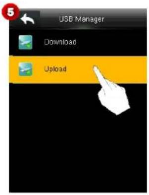
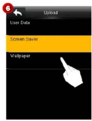
- User Data: Upload all the user information from a USB disk to the device.
Screen Saver
Upload screen saver pictures in a USB disk to the device. After the device enters the standby mode, the uploaded screen saver pictures are displayed. The specific operation is as follows:
- Click Screen Saver (see Figure 6) to enter the Screen Saver interface.
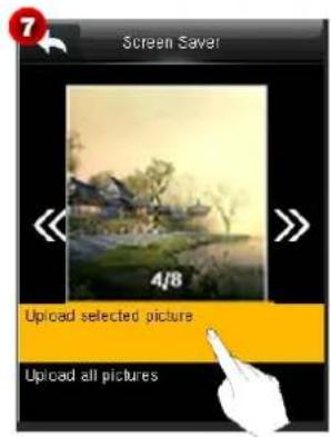
- Click <<>> to switch and select a screen saver picture and click Upload selected picture to upload the selected picture to the device, or click Upload all pictures to upload all pictures that meet requirements in the advertise folder in the USB disk to the device.
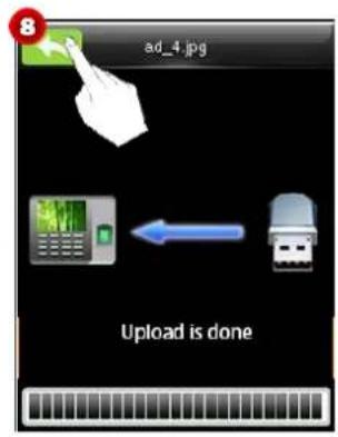
- After the uploading is successful, "Upload is done" is displayed on the screen. Click ↩ to return to the upper-level interface.
- Wallpaper
Upload all wallpaper from a USB disk to the device. The specific operation method is the same as the method of uploading screen saver pictures and is not described here.
Notes:
(1) Before uploading screen saver pictures, put the pictures to be uploaded in the advertise folder in the USB disk.
(2) Before uploading wallpaper, put the wallpaper to be uploaded in the wallpaper folder in the USB disk.
(3) Screen saver pictures and wallpaper must be PNG, JPG, or BMP pictures, with the size not larger than 30 KB.
(4) The names of screen saver pictures and wallpaper contain no more than 20 characters.
11 Attendance Search
The device automatically stores all verification records of users. With the attendance search function, users can query all records conveniently.
- Click Attendance Search in the main menu to enter the User ID interface (see Figure 2).
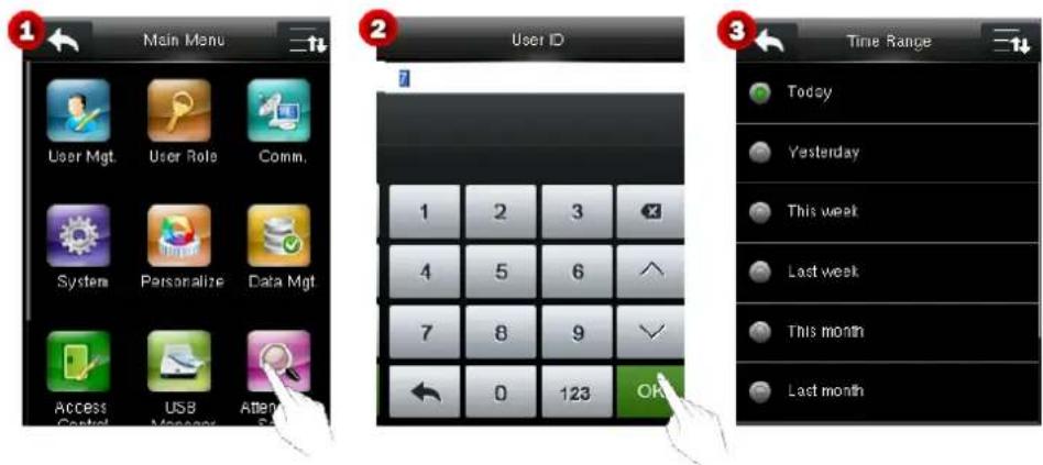
- Enter a user ID and click OK to enter the Time Range interface (see Figure 3).
- Click the time range to be viewed as needed, or click User Defined to specify the start time and end time of records as prompted, and view relevant records.
Note: If you click OK without entering a user ID, verification records of all users in the selected time range are displayed.
12 Autotest
The device automatically tests whether all modules function properly, which include the LCD, voice, fingerprint sensor, finger vein sensor, and real-time clock (RTC).
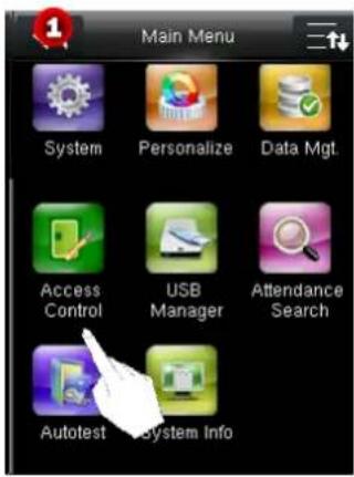
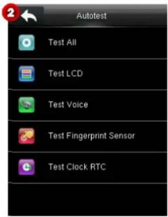
Test All: Test the LCD, voice, fingerprint sensor ★, and RTC. During the test, click the screen to continue with the next test or click ▶ to exit the test.
Test LCD: Test the display effect of the LCD screen by displaying full color, pure white, and pure black to check whether the screen displays colors properly. During the test, click the screen to continue with the next test or click to exit the test.
Test Voice: Test whether the voice files stored in the device are complete and the voice quality is good. During the test, click the screen to continue with the next test or click ↗ to exit the test.
Test Fingerprint Sensor ★: Test whether the fingerprint collector functions properly. During the test, a user presses a fingerprint and checks whether the collected fingerprint image is clear. When a fingerprint is pressed in the collection window, the collected fingerprint image is displayed on the screen in real time. Click ▶ to exit the test.
Test Clock RTC: Test the real-time clock. The device tests whether the clock works properly and accurately by checking the stopwatch. Click ↩ to exit the test.
13 System Information
The system information function allows users to view the storage condition of the device and the device version.
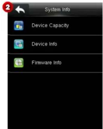
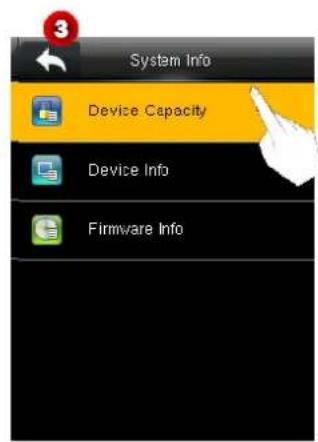
Click System Info in the main menu to enter the System Info interface (see Figure 2).
- Device Capacity
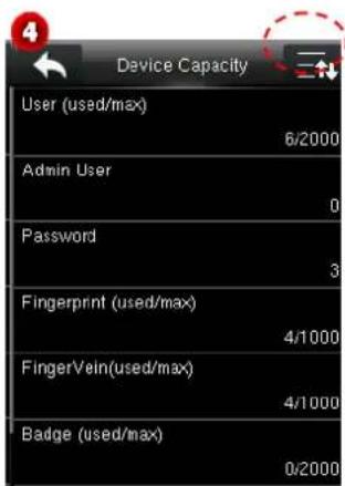
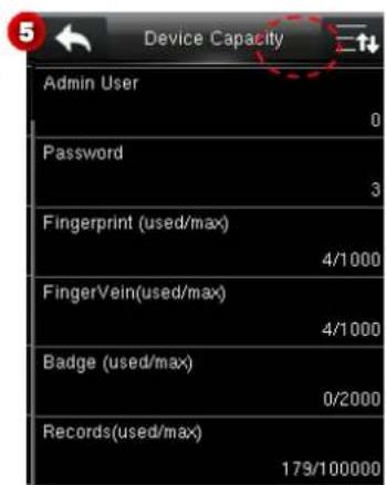
The device displays the number of registered users, number of administrators, passwords, fingerprints, finger veins, number of registered badge numbers★, and access control records in the device.
Click Device Capacity to enter the Device Capacity interface. Click ☐ to scroll down the screen to display more content. (Note: You can click ☐ again to scroll up the screen.)
- Device Info
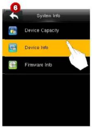
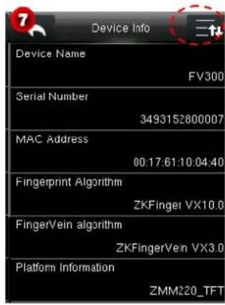
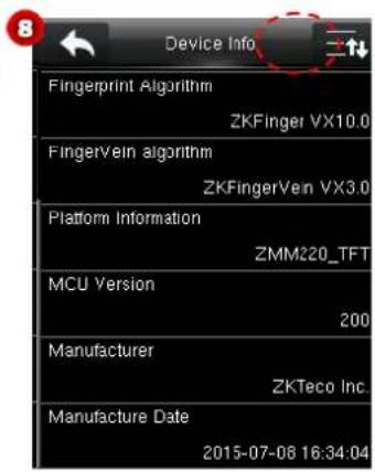
Device Info: Display the device name, serial number, MAC address, finger vein algorithm★, platform information, MCU version★, manufacturer, and manufacturer date.
Click Device Info to enter the Device Info interface. Click 📄 to scroll down the screen to display more content. (Note: You can click 📄 again to scroll up the screen.)
- Firmware Info
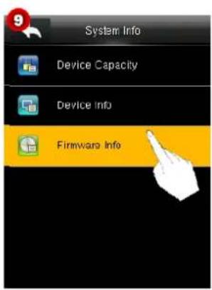
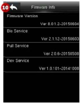
Display the firmware version, Bio service, push service, pull service and Dev service.
Click Firmware Info to enter the Firmwave Info interface.
Appendices
Appendix 1 Text Input Operation Instructions
The device supports Chinese, English, digits, and symbols. Click the place in which texts need to be entered to enter the relevant input interface. For example, click Name to enter the Name interface.
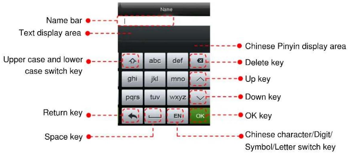
The following step 1 uses the input of the Chinese character zhong as an example.
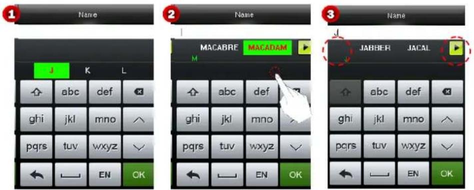
- Click the keypad to enter the Chinese Pinyin zhong. The device displays relevant Chinese Pinyin according to entered letters in the Chinese Pinyin display area (see Figure 1).
- Click and select the Chinese Pinyin corresponding to the Chinese character to be entered. The device displays the corresponding Chinese character in the text display area according to the selected Pinyin (see Figure 2).
Note: You can click ↕ or ▶ to move forwards or backwards to display more texts.
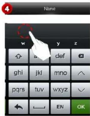
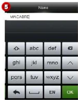
- Click and select the required Chinese character in the text display area (see Figure 4). The selected character is displayed in Name (see Figure 5).
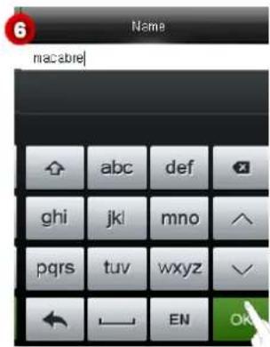
- To enter other texts, repeat steps 1-3. After entering required information, click OK to save the settings and return to the upper-level interface.
Appendix 2 USB
The device serves as a USB host, which can be connected to a USB disk for data exchange.
Traditional finger vein devices support data transmission over RS485 or Ethernet. When the data amount is large, it takes a very long time to transmit data due to limitations of physical conditions. The USB data transmission speed is much faster than any traditional transmission modes. When downloading data using a USB disk, insert the USB disk into device for data downloading and then insert it into a PC to import the data to the PC. In addition, the device supports mutual transmission of user information and finger vein data between two devices, thereby eliminating tedious cable connection for data transmission between traditional devices and PCs.
Appendix 3 Wiegand Introduction
Wiegand26 Protocol is a standard protocol on access control developed by the Access Control Standard Subcommittee affiliated to the Security Industry Association (SIA). It is a protocol used for contactless IC card reader port and output.
The protocol defines the port between the card reader and controller which are widely used in access control, security and other related industries. This has standardized the work of card reader designers and controller manufacturers. The access control devices produced by our company also apply this protocol.
Digital Signal
Figure 1 shows the sequence diagram of the card reader sending digital signal in bits to the access controller. The Wiegand in this diagram follows the SIA access control standard protocol, which targets at 26-bit Wiegand card reader (with a pulse time within 20us to 100us and pulse hopping time within 200 us and 20 ms). Data1 and Data0 signals are high level (greater than Voh) until the card reader is ready to send a data stream. The card reader send out asynchronous low level pulse (less than vol), transmitting data stream via Data1 or Data0 wire to access control box (as the sawtooth wave in figure 1). Data1 and Data0 pulses do not overlap or synchronize. Figure 1 shows the maximum and minimum pulse width (successive pulses) and pulse hopping time (the time between two pulses) allowed by the F series fingerprint access control terminals.
Table1: Pulse Time
| Sign | Definition | Card Reader Typical Value |
| Tpw | Pulse Width | 100 μs |
| Tpi | Pulse Interval | 1 ms |
Figure1: Sequence Diagram
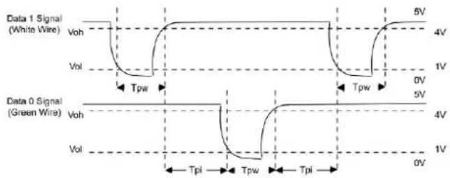
line
| Signal Type | Voltage Level | |-------------|---------------| | Data 1 Signal (White Wire) | 5V | | Data 1 Signal (White Wire) | 4V | | Data 1 Signal (White Wire) | 1V | | Data 0 Signal (Green Wire) | 5V | | Data 0 Signal (Green Wire) | 4V | | Data 0 Signal (Green Wire) | 1V | | Data 0 Signal (Green Wire) | Tpi | | Data 0 Signal (Green Wire) | Tpw | | Data 0 Signal (Green Wire) | Tpi | | Data 0 Signal (Green Wire) | 0V |Appendix 3.1 Wiegand 26 Introduction
The system provides the embedded Wiegand 26-bit format.
Composition of the Wiegand 26-bit format: 2-bit parity check bits and 24-bit output content (user ID or card number). The 24-bit binary code can indicate 16 777 216 (0-16 777 215) different values.
| 1 | 2 | 25 | 26 | |
| Even parity check bit | User ID/Card number | Odd parity check bit | ||
The following table describes the fields.
| Field | Description |
| Even parity check bit | The even parity check bit is determined by bits 2-13. If there is an even number of 1's, the even parity check bit is 0. If there is an odd number of 1's, the even parity check bit is 1. |
| User ID/Card number (bit 2 through bit 25) | User ID/Card number (card code, 0-16777215) and bit 2 indicates the most significant bit (MSB). |
| Odd parity check bit | The odd parity check bit is determined by bits 14-25. If there is an even number of 1's, the odd parity check bit is 1. If there is an odd number of 1's, the odd parity check bit is 0. |
Example: A user with the user ID of 12345 has the card number of 0013378512 and the failure ID is set to 1.
- When the output content is set to user ID, the Wiegand output of the system is as follows after the user passes the verification.

- When the output content is set to card number, the Wiegand output of the system is as follows after the user passes the verification.

- When the verification fails, the Wiegand output of the system is as follows:

Note: When the output content is beyond the preset range of the Wiegand format, the low-order bits are reserved and high-order bits are discarded. For example, if a user ID is 888 888 888, which is 110 100 111 110 110 101 111 000 111 000 in binary system, the last 24 bits, that is, 111 110 110 101 111 000 111 000 are outputted and the first 6 bits 110 100 are discarded because the Wiegand26 format supports 24 bits of output content.
Appendix 3.2 Wiegand 34 Introduction
The system provides the embedded Wiegand 34-bit format.
Composition of the Wiegand 34-bit format: 2-bit parity check bits and 32-bit output content (user ID or card number). The 32-bit binary code can indicate 4 294 967 296 (0-4 294 967 295) different values.
| 1 | 2 | 33 | 34 |
| Even parity check bit | User ID/Card number | Odd parity check bit | |
The following table describes the fields.
| Field | Description |
| Even parity check bit | The even parity check bit is determined by bits 2-17. If there is an even number of 1's, the even parity check bit is 0. If there is an odd number of 1's, the even parity check bit is 1. |
| User ID/Card number (bit 2 through bit 25) | User ID/Card number (card code, 0-4 294 967 295) and bit 2 indicates the MSB. |
| Odd parity check bit | The odd parity check bit is determined by bits 18-33. If there is an even number of 1's, the odd parity check bit is 1. If there is an odd number of 1's, the odd parity check bit is 0. |
Example: A user with the user ID of 123456789 has the card number of 0013378512 and the failure ID is set to 1.
- When the output content is set to user ID, the Wiegand output of the system is as follows after the user passes the verification.

- When the output content is set to card number, the Wiegand output of the system is as follows after the user passes the verification.

- When the verification fails, the Wiegand output of the system is as follows:

Appendix 4 Anti-passback Settings
To avoid some persons following users to enter the door without verification, resulting in security problem, users can enable anti-passback function. The check-in record must match with check-out record so as to open the door.
This function requires two devices to work together: one is installed inside the door (master device) and the other one is installed outside the door (slave device). The two devices communicate via Wiegand signal. The Wiegand format and Output type (User ID / Badge Number) adopted by the master device and slave device must be consistent.
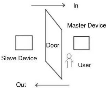
flowchart
graph TD
    A["Slave Device"] --> B["Door"]
    C["User"] --> B
    D["In"] --> B
    E["Out"] --> B
    B --> F["Master Device"]
[Working principle]
The master device supports the Wiegand In function and the slave device supports the Wiegand Out function. After the Wigand output port of the slave device is connected to the Wiegand input port of the master device, Wiegand signals outputted by the slave device cannot contain the device ID and the numbers sent from the slave device to the master device must exist on the master device. That is, the user information on the slave device supporting the anti-passback function must map to the user information on the master device supporting the anti-passback function.
[Function description]
The device detects anti-passback based on the last check-in/check-out record of users. The check-in record must match the check-out record. The device supports out anti-passback, in anti-passback, and in/out anti-passback.
When Out Anti-passback is set for a user on the master device, the last record of the user must be a check-in record if the user needs to check in/out freely. Otherwise, the user cannot check out and the check-out request of the user is rejected because of anti-passback. For example, if the recent first record of a user is a check-in record, the second record of the user can be either a check-in or check-out record but the third record must be based on the second record, ensuring that the check-in record matches the check-out record. Note: If a user has no record, the user can only check in.
When In Anti-passback is set for a user on the master device, the last record of the user must be a check-out record if the user needs to check in/out freely. Otherwise, the user cannot check in and the check-in request of the user is rejected because of anti-passback. Note: If a user has no record, the user can only check out.
When In/Out Anti-passback is set for a user on the master device, if the last record of the user is a check-out or check-in record, the next record of the user must be a check-in or check-out record for the user to check in/out freely. That is, the check-in record must match the check-out record.
[Operation description]
(1) Model selection
Master device: devices supporting the Wiegand In function, except the F10 reader
Slave device: devices supporting the Wiegand Out function
(2) Menu settings
Anti-Passback Direction
The options of Anti-Passback Direction include In/Out Anti-passback, Out Anti-passback, In Anti-passback, and No Anti-passback
Out Anti-passback: After a user checks out, only if the last record is a check-in record can the user check out again.
In Anti-passback: After a user checks in, only if the last record is a check-out record can the user check in again.
Device Status
The options of Device Status include None, Out, and In.
None: To disable the Anti-Passback function.
Out: All records on the device are check-out records.
(3) Modifying the Wiegand output format for the device
When two devices communicate with each other, only Wiegand signals that do not contain the device ID are acceptable. You can choose Comm. > Wiegand Setup from the main menu or access the software and choose Basic Setting > Device Management > Wiegand and set Defined Format to Wiegand26-bits or Wiegand26 without device ID.
(4) User registration
User IDs must exist on both the master and slave devices and the user IDs must be consistent. Therefore, users need to be registered on both the master and slave devices.
(5) Wiring description
The master and slave devices communicate with each other over Wiegand and the wiring is as follows:
| Master device Slave device | ||
| IND0 | <----> | WD0 |
| IND1 | <----> | WD1 |
| GND | <----> | GND |
17.7 Statement on Human Rights and Privacy
Dear Customers:
Thank you for choosing the hybrid biometric products designed and manufactured by us. As a world-renowned provider of biometric technologies and services, we pay much attention to the compliance with the laws related to human rights and privacy in every country while constantly performing research and development.
We hereby make the following statements:
- All of our fingerprint recognition devices for civil use only collect the characteristic points of fingerprints instead of the fingerprint images, and therefore no privacy issues are involved.
- The characteristic points of fingerprints collected by our products cannot be used to restore the original fingerprint images, and therefore no privacy issues are involved.
- We, as the equipment provider, shall not be held legally accountable, directly or indirectly, for any consequences arising due to the use of our products.
- For any dispute involving the human rights or privacy when using our products, please contact your employer directly.
Our fingerprint products for police use, or development tools support the collection of the original fingerprint images. As for whether such a type of fingerprint collection constitutes an infringement of your privacy, please contact the government or the final equipment provider. We, as the original equipment manufacturer, shall not be held legally accountable for any infringement arising thereof.
The law of the People's Republic of China has the following regulations regarding the personal freedom:
- Unlawful arrest, detention or search of citizens of the People's Republic of China is prohibited; infringement of individual privacy is prohibited.
- The personal dignity of citizens of the People's Republic of China is inviolable.
- The home of citizens of the People's Republic of China is inviolable.
- The freedom and privacy of correspondence of citizens of the People's Republic of China are protected by law.
At last we stress once again that biometrics, as an advanced recognition technology, will be applied in a lot of sectors including e-commerce, banking, insurance and legal affairs. Every year people around the globe suffer from great loss due to the insecurity of passwords. The biometric products actually provide adequate protection for your identity under a high security environment.
17.8 Environment-Friendly Use Description

- The Environment Friendly Use Period (EFUP) marked on this product refers to the safety period of time in which the product is used under the conditions specified in the product instructions without leakage of noxious and harmful substances.
- The EFUP of this product does not cover the consumable parts that need to be replaced on a regular basis such as batteries and so on. The EFUP of batteries is 5 years.
Names and Concentration of Toxic and Hazardous Substances or Elements
| Parts Name | Toxic and Hazardous Substances or Elements | |||||
| Pb | Hg | Cd | Cr6+ | PBB | PBDE | |
| Chip resistor | × | ○ | ○ | ○ | ○ | ○ |
| Chip capacitor | × | ○ | ○ | ○ | ○ | ○ |
| Chip inductor | × | ○ | ○ | ○ | ○ | ○ |
| Chip diode | × | ○ | ○ | ○ | ○ | ○ |
| ESD components | × | ○ | ○ | ○ | ○ | ○ |
| Buzzer | × | ○ | ○ | ○ | ○ | ○ |
| Adapter | × | ○ | ○ | ○ | ○ | ○ |
| Screws | ○ | ○ | ○ | × | ○ | ○ |
| ○: Indicates that this toxic or hazardous substance contained in all of the homogeneous materials for this part is below the limit requirement in SJ/T11363-2006.×: Indicates that this toxic or hazardous substance contained in at least one of the homogeneous materials for this part is above the limit requirement in SJ/T11363-2006.Note: 80% of the parts in this product are manufactured with non-hazardous environment-friendly materials. The hazardous substances or elements contained cannot be replaced with environment-friendly materials at present due to technical or economical constraints. | ||||||
- Control Series Product
- About This Manual
- Important Statement
- Contents
- Guidance Notes....1
- Main Menu....13
- User Management ....15
- User Role....25
- Comm. Settings....28
- System Settings....34
- Personalize Settings....38
- Data Mgt. 43
- Access Control....47
- USB Manager....55
- Attendance Search....57
- Autotest....58
- System Information....59
- Appendices....61
- Guidance Notes
- Product Functions
- Finger vein function
- User access control
- USB disk function
- Communication over RS485 or Ethernet
- Modes of Enrollment and Verification of Finger Veins & Fingerprints★
- Recommended fingers: index finger and middle finger
- Finger placement
- Vein verification procedure
- Method of Pressing Fingerprint★
- Correct way to press the fingerprint:
- Wrong ways to press the fingerprint:
- Usage of the Touch Screen
- Verification Modes
- Finger Vein and Fingerprint Verification ★
- ◆ 1:N verification
- ◆ 1:1 verification
- Password Verification
- Card Verification★
- Combined Verification
- Combined Verification for Unlocking
- Notes:
- Product Appearance and Terminal Blocks
- Product Appearance
- Terminal Blocks
- Initial Interface
- Main Menu
- User Management
- Adding a User
- Entering a User ID
- Entering a Name
- User Role
- Registering a Finger Vein and Fingerprint
- Enrolling a Badge Number ★
- Enrolling a Password
- Setting Access Control Level
- - Setting an access group
- - Setting a time period
- All Users
- Querying a User
- Editing/Deleting a User
- - Deleting a user
- Display Style
- User Role
- - Enable Defined Role
- Name
- - Define User Role
- Comm. Settings
- Ethernet Settings
- Serial Comm. Settings
- PC Connection
- Device ID Settings
- Wiegand Setup
- Wiegand Input
- Wiegand Output
- Card Format Detect Automatically
- System Settings
- Date/Time Settings
- Access Logs Setting★
- FV&FP Parameter Setting★
- Reset to Factory Settings
- USB Upgrade
- Personalize Settings
- User Interface Settings
- - Wallpaper
- Voice Settings
- Bells Settings
- New Bell Schedule
- Bell Status
- Bell Time
- - Repeat
- Ring Tone
- All Bell Schedules
- Data Mgt.
- Delete Data
- - Delete Screen Savers
- Backup Data
- - Backup to Device
- - Backup to USB Disk
- Restore Data
- - Restore from Device
- - Restore from USB Disk
- Access Control
- To gain access, the registered user must meet the following conditions:
- Access Control Options Settings
- Time Schedule Settings
- - Editing a Time Rule
- Holidays Settings
- Add Holiday
- No.
- Date
- - holiday type
- - Looping or not
- Include Holidays
- Combined Verification Settings
- Anti-passback Settings
- Anti-Passback Direction
- USB Manager
- USB Download
- USB Upload
- Attendance Search
- Autotest
- System Information
- - Device Capacity
- - Device Info
- - Firmware Info
- Appendices
- Appendix 1 Text Input Operation Instructions
- The following step 1 uses the input of the Chinese character zhong as an example.
- Appendix 2 USB
- Appendix 3 Wiegand Introduction
- Digital Signal
- Appendix 3.1 Wiegand 26 Introduction
- Appendix 3.2 Wiegand 34 Introduction
- Appendix 4 Anti-passback Settings
- [Working principle]
- [Function description]
- [Operation description]
- Statement on Human Rights and Privacy
- Dear Customers:
- We hereby make the following statements:
- The law of the People's Republic of China has the following regulations regarding the personal freedom:
- Environment-Friendly Use Description
Brand : ZKTeco
Model : FV350
Category : Access Control