
SBTL8200 - Access Control ZKTeco - Free user manual and instructions
Find the device manual for free SBTL8200 ZKTeco in PDF.


| Product Type | Speed Gate / Swing Turnstile |
| Model | SBTL8200 |
| Series | SBTL8000 Series |
| Dimensions (L x W x H) | 1600 mm x 120 mm x 1022 mm |
| Chassis Material | SUS304 Stainless Steel |
| Input Voltage | AC 110~240V, 50-60 Hz |
| Output Voltage | DC 24V |
| Communication | CAN |
| Operating Temperature | -28°C to 60°C |
| Relative Humidity | 20% - 95% (Non-condensing) |
| Passage Rate | Maximum 30 persons/minute |
| Opening/Closing Time | 0.8 seconds (adjustable) |
| Infrared Sensors | 10 sensors for detection and safety |
| Working Environment | Indoor |
| Main Functions | Access control, multiple working modes, emergency release, anti-tailgating, anti-pinch |
| Working Modes | Normal, Normally Open, Normally Closed, Test mode |
| Passing Modes | Two-way swipe, Left free/Right swipe, etc. (9 modes) |
| Opening Duration (Auto-close) | 2 to 60 seconds (default 5 seconds) |
| Display | LCD screen on control board |
| Control Buttons | UP, DOWN, ENT, ESC |
| Security Features | Emergency lock release for evacuation, reverse intrusion detection, trailing alarm, anti-pinch IR zones |
| Maintenance | Regular surface cleaning with soft cloth, lubricate transmission, check connections; professional only for electrical |
Frequently Asked Questions - SBTL8200 ZKTeco
User questions about SBTL8200 ZKTeco
0 question about this device. Answer the ones you know or ask your own.
Ask a new question about this device
Download the instructions for your Access Control in PDF format for free! Find your manual SBTL8200 - ZKTeco and take your electronic device back in hand. On this page are published all the documents necessary for the use of your device. SBTL8200 by ZKTeco.
USER MANUAL SBTL8200 ZKTeco
Speed gates SBTL8000 series
Applicable Model(s): SBTL8000, SBTL8011, SBTL8022, SBTL8033, SBTL8200, SBTL8211, SBTL8222, SBTL8233
Version: 1.0
Date: June 2019
Contents
1. Product Introduction.... 1
1.1 Model number and access control.... 1
1.2 Chassis design and dimensions.... 1
1.3 The mechanical system of the speed gates 2
1.4 Electric control system 2
1.5 Operation principle of the speed gates....3
1.6 System composition of the product....4
1.7 Specifications....4
2. Installation of the Product 5
2.1 Installation notes....5
2.2 Installation position of the speed gates 5
2.3 Cables installation and fixing 6
3. Menus 9
3.1 Menu operations....9
3.2 Menus 9
3.3 Functions introduction of wiring and terminal 12
4. Troubleshooting 13
5. Product Maintenance....14
5.1 Chassis....14
5.2 Movement....14
5.3 Power 14
1. Product Introduction
1.1 Model number and access control
| Access Model | None | C3-200 and 2*Wiegand reader | inBio 260 and 2* FR1500/ID reader | 2*Facedepot 7B device |
| SBTL8000 | √ | |||
| SBTL8011 | √ | |||
| SBTL8022 | √ | |||
| SBTL8033 | √ | |||
| SBTL8200 | √ | |||
| SBTL8211 | √ | |||
| SBTL8222 | √ | |||
| SBTL8233 | √ |
Figure 1-1
1.2 Chassis design and dimensions
The SUS304 stainless steel body looks simple and clean and is anti-corrosion. The SBTL8000 series grants legal access to the authorized persons and restricts illegal access. In case of an emergency, the lock will release to allow fast evacuation and egress.
Below is the design and dimensions of SBTL8000:
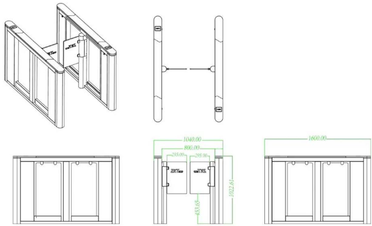
Figure 1-2
1.3 The mechanical system of the speed gates
The mechanical system of the swing turnstile is composed of the cabinet and the core mechanism. The cabinet is equipped with the mode indicator, the infrared sensor, and the locking system. The core mechanism mainly consists of the motor, the chassis, the core, and the swing arm (the glass panel).
1.4 Electric control system
The electric control system of the swing turnstile is mainly composed of the master control panel, the infrared sensor, the mode indicator, and the loudspeaker.
Master control panel: The master control panel is the core part of the control system that receives signals from the photoelectric switch, performs logical judgment and processing of these signals, and issues executive commands to the mode indicator, the servo motor driver and the loudspeaker.
Infrared sensor: It detects the location of the pedestrian and plays a safe protection function.
Mode indicator: This indicator shows the current passing mode status of the channel and guides the passenger to pass the passage orderly and safely.
Loudspeaker: The system will trigger the alarm if it detects any unauthorized entry to the lane.
1.5 Operation principle of the speed gates
When the device is connected to the power, the system will perform self-check. The device will operate normally if no problem is detected. If a failure is detected, the system will display related messages on the LCD display screen so that the user can have a quick knowledge of and solve the problem.
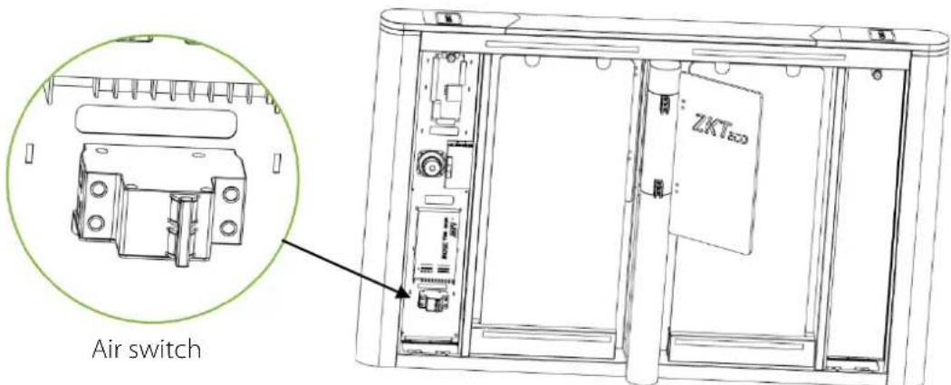
Figure 1-3
When the reader detects a valid card/fingerprint, the display screen will show whether it is successful or not. And the switch instruction signal is transmitted to the master control panel.
After receiving the signal from the reader and the infrared sensor, the master control panel will send valid control signals to the servo motor driver. At this time, if the system is in forbidden passing mode, the mode indicator light will turn red, and the master control panel will not accept signals of card swiping/fingerprint scanning.
After the passenger passes the channel according to the opening direction of the swing arm, the infrared sensor will keep detecting the movement of the pedestrian throughout the passage and continue to deliver signals to the main control panel until the pedestrian passes through the passage.
If the pedestrian enters the passage but forgets to swipe his/her card, or if the card held by the passenger is invalid, the system will prompt an audible alarm to warn the pedestrian to stop passing. The alarm signal will not be cancelled until the passenger retreats from the passage. A pedestrian can pass through the lane only after successful verification with a valid card read by the card reader.
1.6 System composition of the product
The single-passage management system is composed of two single-core speed gates. The multi-passage management system is composed of two single-core barriers and multiple dual-core barriers.
Working modes of the system
To meet different needs, this system provides multiple working modes for users, including the normal working mode, normally open mode, normally closed mode, and testing mode.
After supplying power to the device, the LCD screen on the control board will display a default state, which is the current working mode.
1.7 Specifications
| Dimension (mm) | SBTH1000: L = 1600, W =120, H = 1022 | ||
| Communication | CAN | Input voltage | AC110~240V, 50-60Hz |
| Input control signal | Switching signal | Output voltage | DC 24V |
| Time of opening/closing | 0.8 Sec (adjustable) | Relative humidity | 20% - 95%(Non-condensing) |
| Temperature | -28°C to 60°C | Passage rate | Maximum 30/minute |
| Infrared sensor | 10 | Working environment | Indoor |
2. Installation of the Product
2.1 Installation notes
1) It is recommended that the speed gates must be installed on a horizontal solid platform with a height of 50mm to 100mm.
2) It is also recommended that the swing turnstile should not be used in a corrosive environment.
3) Make sure the protective ground wire of the system is reliably connected to avoid personal injuries or other accidents.
4) The equipment shell is made of stainless steel. You may gently remove any dirt or dust on the surface with a soft and smooth fabric. Do not scrub the surface with hard objects. Do not rinse the device with water, otherwise there may be short circuit or damaging the equipment.
5) After installation, check if the connection is done correctly at the connecting points of the protective ground wire, at the connector assemblies and wiring points of the circuits, as well as at each movable part of the speed gates turnstile. Any loose nuts, screws and other fasteners should be tightened in time to avoid speed gates turnstile failures caused by longer operations.
2.2 Installation position of the speed gates
A distance of 100mm between the speed gates turnstile and the wall needs to be reserved for ease of opening the top cover of the machine to perform maintenance and adjustment. The reference figure is shown below:
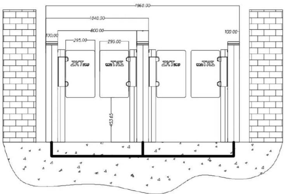
Figure 2-2
2.3 Cables installation and fixing
For the outlets of the concealed cables, please refer to the drawing indicating the mounting holes. The input voltage for this swing turnstile is AC110-220V, and its master and slave are connected with an 8-core cable (signal) and a 2-core cable (power). When installing the speed gates turnstile, the user only needs to connect it to the corresponding ports. Note that the PVC conduits are laid 100mm under the ground, with the height of the exposed part not exceeding 100mm. In addition, the conduit outlet is bent to prevent the ingress of water into the conduit.
SBTL 8000 series installation holes and cabling positions are as shown in Figure 2-3a:
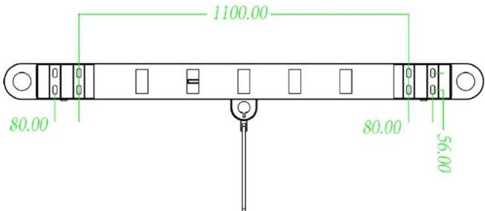
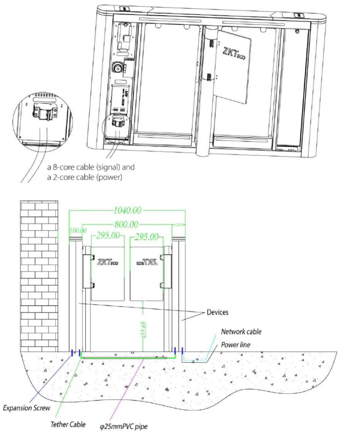
Figure 2-3a
Mark the anchor hole at the centre of the stand, and the edge of the chassis base on the ground according to the size as shown in Figure 2-3a. Use a hammer drill to drill M12 screw holes, then install the screws. Place the swing turnstile according to the size and respective installation position as shown in the figure before installation and fixing. Connect the turnstile to the power supply and
perform a power-on test. If the test is passed, tighten the screws. It is recommended to mark a warning line on the ground, as shown in Figure 2-3b, after installing the device to remind the pedestrian to stand behind the line when swiping the card.
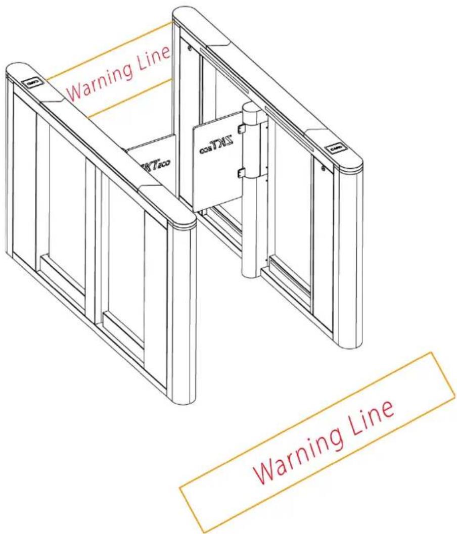
Figure 2-3b
3. Menus
3.1 Menu operations
- Operating instruction
1) After powered on, the LCD screen on the control board will display the default state showing the current working mode.
2) There are 4 buttons on the control board: UP, DOWN, ENT, and ESC, as shown in Figure 3-1.
UP: to move upwards or increase the value.
DOWN: to move downwards or decrease the value.
ENT: to enter a menu setting item or confirm the current modified value.
ESC: to return to the previous menu or cancel the current operation.
3) Operation and instruction of menu
Press the ENT button and enter the password input interface. The default password is: UP, UP, DOWN, DOWN, DOWN, DOWN. You may press the ESC button to erase the last input. After entering the menu, press UP or DOWN to choose a menu item, then press ENT to enter the interface and adjust such function or value.
3.2 Menus
1. Position adjustment of the swing barrier
Type: zero (default)
Left limit
Right limit
2. Passing mode
Opening mode: Two-way swipe (default)
Left free, Right swipe
Left swipe, Right free
Two-way free
Left prohibit, Right swipe
Left swipe, Right prohibit Left prohibit, Right free Left free, Right prohibit Two-way prohibit
3. Opening duration (Press 'ENT' to modify)
After the gate is opened, it will automatically close if no one passes through within a certain time duration. The default value is 5 seconds. The value ranges from 2 to 60.
4. Reverse intrusion
Mode: Close the door and voice alarm Voice alarm only (default) Turn off reverse detection
5. Trailing alarm detection
Mode: Turn off trailing detection Voice alarm only (default) Close the door and voice alarm
6. Opening speed
Speed value: 1\~20 (default 1)
7. Closing speed
Speed value: 1\~20 (default 1)
8. Swiping mode
Method: Allow the card to be swiped in the channel (default) Do not allow card swiping in the channel
9. Reset counter
Reset: Out counter (default) Into the counter All
10. Gate closing delay time
Time: 0\~10 (default 0)
11. Brake unlock mode
Mode: Delay unlock (default)
12. Brake starting angle
Angle: 1\~10 (default 3)
13. Fire alarm signal
Signal: right open
Left open (default)
Shut down
14. Volume setting
Volume: off
The value ranges from 1 to 16 (default 5).
1 is the minimum value; 16 is the maximum value.
15. Audio prompt for gate opening swift
Enable or not: No (default)
Yes
16. Infrared anti-pinch
Mode: Turn off the anti-pinch feature
Enabling anti-pinch (default)
17. Infrared anti-pinch area
Area selection: Disable during In and out of infrared (default)
All infrared zone anti-pinch
18. Memory opening
Whether to open: No (default)
Yes
19. System working mode
Mode: working mode (default)
Test mode
Restore to factory
20. Version number:
Version: V9.0.0
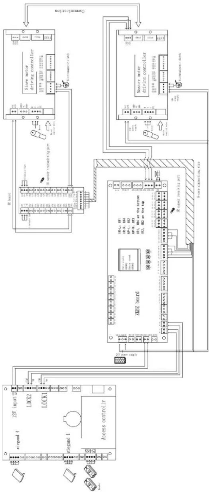
3.3 Functions introduction of wiring and terminal
flowchart
graph TD
    A["Smart Control"] --> B["Slave motor driving controller"]
    B --> C["Master motor driving controller"]
    C --> D["ZKRZ board"]
    D --> E["Access control"]
    E --> F["20V power supply"]
    F --> G["Power Supply"]
    G --> H["Sensor switching port"]
    H --> I["IR band"]
    I --> J["IR band"]
    J --> K["IR band"]
    K --> L["IR band"]
    L --> M["IR band"]
    M --> N["IR band"]
    N --> O["IR band"]
    O --> P["IR band"]
    P --> Q["IR band"]
    Q --> R["IR band"]
    R --> S["IR band"]
    S --> T["IR band"]
    T --> U["IR band"]
    U --> V["IR band"]
    V --> W["IR band"]
    W --> X["IR band"]
    X --> Y["IR band"]
    Y --> Z["IR band"]
    Z --> AA["IR band"]
    AA --> AB["IR band"]
    AB --> AC["IR band"]
    AC --> AD["IR band"]
    AD --> AE["IR band"]
    AE --> AF["IR band"]
    AF --> AG["IR band"]
    AG --> AH["IR band"]
    AH --> AI["IR band"]
    AI --> AJ["IR band"]
    AJ --> AK["IR band"]
    AK --> AL["IR band"]
    AL --> AM["IR band"]
    AM --> AN["IR band"]
    AN --> AO["IR band"]
    AO --> AP["IR band"]
    AP --> AQ["IR band"]
    AQ --> AR["IR band"]
    AR --> AS["IR band"]
    AS --> AT["IR band"]
    AT --> AU["IR band"]
    AU --> AV["IR band"]
    AV --> AW["IR band"]
    AW --> AX["IR band"]
    AX --> AY["IR band"]
Figure 3-2
4. Troubleshooting
| Number | Failure descriptions | Analysis and solution |
| 1 | The mode indicator light does not respond or the indication is incorrect. | Check that the control panel mode indicator wiring is correct or that the contact is poor. |
| 2 | After swiping the card, there is only a speed gate unlocked. | Check the mode setting of the master and slave devices and the 8-core, 2-core connection lines. See the wiring diagram for the specific connection circuit. |
| 3 | The barrier doesn’t close when the opening delay time is ended. | Check to see if the opening delay time is too long or whether the IR sensor is covered. |
| 4 | When the gate is self-tested, the swing arm is not in the normal closing position! | In the process of self-test, there are obstacles, please remove the obstacles, restart the self-test after power-on! |
5. Product Maintenance
5.1 Chassis
The chassis is made of SAE 304 stainless steel. When the device has been used for a long period, there may be rust or stain on the surface of the chassis. Remember to regularly sand the surface along the grain softly and carefully, then coat the surface with anti-rust oil. Avoid covering the infrared sensors.
5.2 Movement
Cut off the power supply before maintenance. Then, open the door, wipe off dust on the surface, and lubricate the transmission mechanism. Check and tighten others connection parts.
5.3 Power
Cut off the power supply before maintenance. Check the plug connection; if anything is loose, fix it. Do not randomly change any connection positioning. Check the external power supply insulation regularly. Do periodic check for any kind of leakage. Check if the technical parameters of each interface are normal. Check the service life of the electronic components.
Caution: The above-mentioned maintenance method of the speed gates, especially the movement and the electric control maintenance, must be carried out by professional personnel. Always remember to cut off the power supply before maintenance and repair.
www.zkteco.eu
- Speed gates SBTL8000 series
- Contents
- Product Introduction.... 1
- Installation of the Product 5
- Menus 9
- Troubleshooting 13
- Product Maintenance....14
- Product Introduction
- Model number and access control
- Chassis design and dimensions
- The mechanical system of the speed gates
- Electric control system
- Operation principle of the speed gates
- System composition of the product
- Working modes of the system
- Specifications
- Installation of the Product
- Installation notes
- Installation position of the speed gates
- Cables installation and fixing
- Menus
- Menu operations
- - Operating instruction
- Menus
- Position adjustment of the swing barrier
- Passing mode
- Opening duration (Press 'ENT' to modify)
- Reverse intrusion
- Trailing alarm detection
- Opening speed
- Closing speed
- Swiping mode
- Reset counter
- Gate closing delay time
- Brake unlock mode
- Brake starting angle
- Fire alarm signal
- Volume setting
- Audio prompt for gate opening swift
- Infrared anti-pinch
- Infrared anti-pinch area
- Memory opening
- System working mode
- Version number:
- Functions introduction of wiring and terminal
- Troubleshooting
- Product Maintenance
- Chassis
- Movement
- Power
Brand : ZKTeco
Model : SBTL8200
Category : Access Control