
SBTL5200 - Access Control ZKTeco - Free user manual and instructions
Find the device manual for free SBTL5200 ZKTeco in PDF.


| Product Type | Access Control Terminal |
| Brand | ZKTeco |
| Model | SBTL5200 |
| Dimensions (H x W x D) | 168 x 78 x 37 mm |
| Weight | 0.5 kg |
| Power Supply | 12V DC, 1.5A |
| Display | 2.8-inch TFT color screen |
| Authentication Methods | Fingerprint, RFID card, Password |
| Fingerprint Sensor | Optical, 500 DPI |
| Card Types Supported | 125 kHz RFID (EM, HID Prox) |
| Communication Interfaces | TCP/IP, RS485, USB Host |
| Fingerprint Capacity | 3,000 templates |
| Card Capacity | 10,000 cards |
| Transaction Log Capacity | 100,000 records |
| Operating Temperature | 0°C to 45°C |
| Operating Humidity | 20% to 80% RH |
| Installation Type | Wall-mounted (vertical) |
| Included Accessories | Power adapter, mounting plate, screws, user manual |
| Maintenance | Clean sensor with soft dry cloth; avoid liquids |
| Security Features | Anti-passback, tamper alarm, encrypted communication |
| Spare Parts & Repairability | Replacement sensors and boards available; contact ZKTeco support |
Frequently Asked Questions - SBTL5200 ZKTeco
User questions about SBTL5200 ZKTeco
0 question about this device. Answer the ones you know or ask your own.
Ask a new question about this device
Download the instructions for your Access Control in PDF format for free! Find your manual SBTL5200 - ZKTeco and take your electronic device back in hand. On this page are published all the documents necessary for the use of your device. SBTL5200 by ZKTeco.
USER MANUAL SBTL5200 ZKTeco
Swing Barrier SBTL5000 series
Applicable Models: SBTL5000/5200, 5011/5211, 5022/5222
Version: 1.0
Date: Jan, 2018
Content
- Product Introduction.... 1
1.1 Model number and access control.... 1
1.2 Chassis design and dimensions.... 1
1.3 Mechanical system of the swing barrier....2
1.4 Electronic control system....2
1.5 The working principle of swing barrier 2
1.6 System composition of the product....3
1.7 Specification....4
- Installation of the Product 4
2.1 Installation notes....4
2.2 Installation position of the swing barrier 5
2.3 Cables installation and fixing 5
- Menu Introduction....7
3.1 Function introduction....7
3.2 Menu introduction....7
3.3 Functions introduction of wiring and terminal....12
-
Troubleshooting....13
-
Product Maintenance....14
5.1 Chassis maintenance....14
5.2 Movement maintenance....14
5.3 Power maintenance....14
1. Product Introduction
1.1 Model number and access control
| Access Model | None | C3-200 and 2*Wiegand reader | inBio 260 and 2* FR1500/ID reader |
| SBTL5000 | √ | ||
| SBTL5011 | √ | ||
| SBTL5022 | √ | ||
| SBTL5200 | √ | ||
| SBTL5211 | √ | ||
| SBTL5222 | √ |
1.2 Chassis design and dimensions
SBTL5000 series is with SUS304 housing, provides simple and beautiful design with anti-corrosion. It provides legal access to the persons while eliminating illegal personnel access. In case of emergency, it ensures that evacuation passage runs smoothly and is convenient for personnel.
SBTL5000's appearance and dimensions are as shown in Figure 1-2:
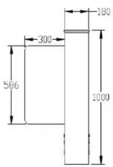
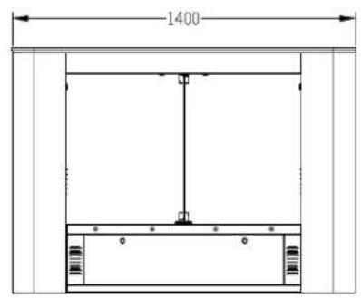
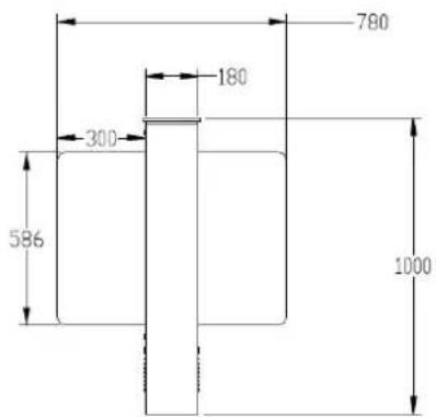
Figure 1-2
1.3 Mechanical system of the swing barrier
The mechanical system of a swing barrier turnstile includes the chassis and the core component. The chassis is a carrier where the direction indicator, the reader, the Infrared sensor, and the door lock are installed. The core component mainly consists of the motor, the frame, the belt, and the swing arm.
1.4 Electronic control system
The electronic control system of a swing barrier turnstile is mainly composed of the reader, the master control panel, the access controller, the infrared sensor, the direction indicator, the alarm, and the transformer.
Reader: The reader reads the data in the card and sends it to the controller.
Master control panel: The master control panel is the system's control center that receives signals from the reader and the photoelectric switch, performs logical judgment and processing of these signals, and sends executive commands to the direction indicator, the electric motor and the alarm.
Infrared sensor: It detects the position of a pedestrian and plays the role of safety protection.
Direction indicator: This indicator displays the current status of the sign at the lane, and directs the pedestrian to pass through the lane in a safe and orderly manner.
Alarm: The alarm gives an alarm voice if the system detects any unauthorized entry to the lane.
1.5 The working principle of swing barrier
◆ After powered on, the system performs self-check. If no failure is detected, the machine starts to operate normally. If a failure is detected, the system displays related messages on the LCD display screen so that the user can have a quick knowledge of and solve the problem.
When the reader detects a valid card, the buzzer will give a nice audible prompt to the pedestrian, indicating that the card is being read successfully. And then, the reader sends signals to the access controller to request permission to pass through the lane. The access controller will send the signal to the master control panel.
◆ After receiving the signal from the access controller, the master control panel sends valid control signals to the direction indicator and the electric motor. And the direction arrow turns green.
◆ Pedestrians passes through the lane according to the direction indicator signs, infrared sensors detect the pedestrians pass through the whole process, and continue send signal to the master control board until the pedestrian has been completely through the lane.
If the pedestrian enters the passage but forgets to flash the card read by the reader, or if the card held by the pedestrian is invalid, the system will stop the pedestrian, and give an audible alarm until the pedestrian retreats from the lane. The pedestrian can pass through the lane only after a valid card is read by the card reader.
1.6 System composition of the product
The single-lane management system is composed of two single-core swing barrier turnstile. The multi-lane management system is composed of two single-core barriers and multiple dual-core barriers.
Working modes of the system
To meet the requirements of being used in different places, this system provides multiple working modes for the user. Including normal working mode, normally open and normally close mode, testing mode.
After powered on, the LCD screen on control board will display a default state, which displays currently work mode.
1.7 Specification
| Dimension(mm) | SBTL5000 Series: L=1400, W=180, H=1000 | ||
| Communication | RS485 | Input voltage | AC100~240V, 50-60Hz |
| Input control signal | Switching signal | Output voltage | DC 24V |
| Time of opening/closing | 0.8S(adjustable) | Relative humidity | 20%-95% ( Non-condensing ) |
| Temperature | -28°C-60°C | Passage rate | Maximum 30/minute |
| Infrared sensor | 6 | Working environment | Indoor |
2. Installation of the Product
2.1 Installation notes
1) It is recommended that the swing barrier turnstile be installed on a horizontal solid platform with 50mm to 100mm in height.
2) It is also recommended that the swing barrier turnstile should not be used in corrosive environment.
3) Make sure the protective ground wire of the system is reliably connected to avoid personal injuries or other accidents.
4) After installation, check whether connection is reliable at the connecting points of the protective ground wire, at the connector assemblies and wiring points of the circuits, as well as at each movable part of the swing barrier turnstile. Any loose nuts, screws and other fasteners should be tightened in time to avoid swing barrier turnstile failures caused by long-time operations.
2.2 Installation position of the swing barrier
A distance of 100mm between the swing barrier turnstile and the wall needs to be reserved for ease of opening the top cover of the machine to perform maintenance and adjustment. The reference figure as below:
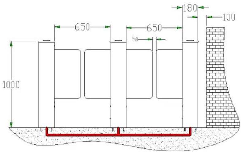
Figure 2-2 SBTL5000 series dual-lane
2.3 Cables installation and fixing
For the outlets of the concealed cables, please refer to the drawing showing the mounting holes. The input voltage for this swing barrier turnstile is AC100-120V/200-240V and its master and slave are connected by a 5-core cable (signal) and a 2-core cable (power). When installing this swing barrier turnstile, the user only needs to connect it to the corresponding ports. Note that the PVC conduits are buried 100mm under the ground, with the height of the exposed part not exceeding 100mm. In addition, the conduit outlet is bent back to prevent ingress of water into the conduit.
SBTL 5000 series installation holes and cabling positions as shown in Figure 2-3a:
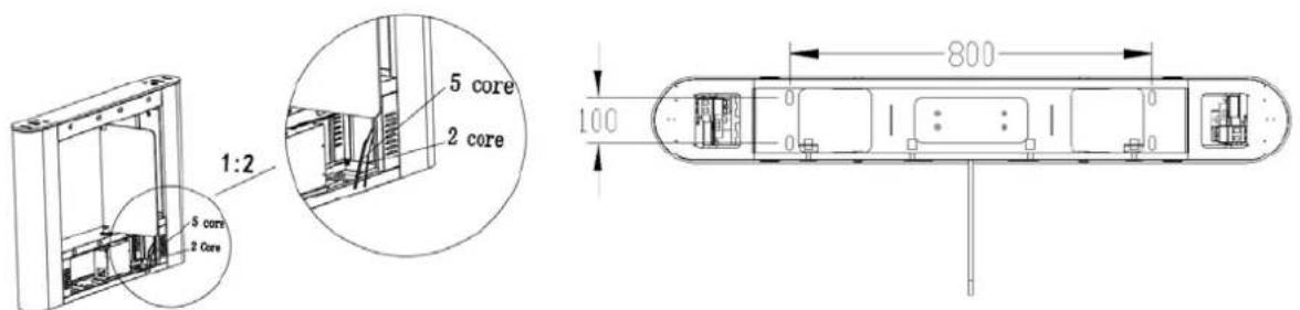
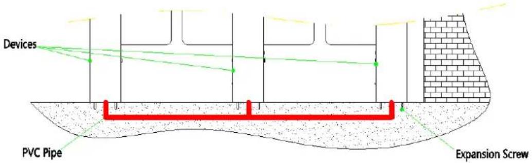
Figure 2-3a
Mark the screw hole centre of the stand, and the edge of the chassis base on the ground according to the sizes as shown on the Figure 2-3a. Use a hammer drill to perforate M12 screw holes and then install the screws. Place the swing barrier turnstile according to the sizes and positions as shown in the figure before installation and fixing. Connect the online cables and perform the power-on test. If the test is OK, tighten the screws. It is recommended that a warning line be marked out on the ground after the machine is installed, so as to prompt the pedestrian to stand behind the warning line when swiping the card. As shown in Figure 2-3b:
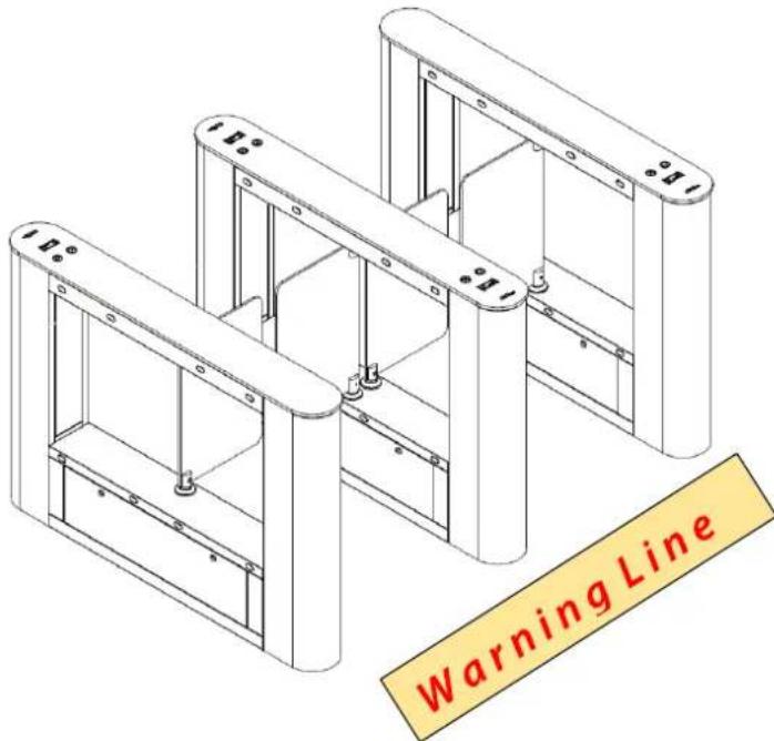
Figure 2-3b
3. Menu Introduction
3.1 Function introduction
1) After powered on, the LCD screen on control board will display a default state, which displays current work mode.
2) There are 4 buttons 'UP, DOWN, ENT, ESC' on the control board, show as Figure 3-1:
UP: to move up menu item or increase the value.
DOWN: to move down menu item or decrease the value.
ENT: to enter menu setting item or confirm the current modified value.
ESC: to return to the previous menu or to cancel the current operation.
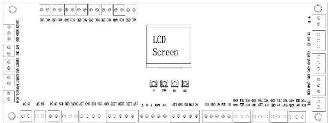
Figure 3-1
3) Operation and instruction of menu
Press the ENT button, enter the password input interface, the default password is: UP, UP, DOWN, DOWN, DOWN, DOWN. If any step fails please press the ESC button to get back. After entering the menu press UP or DOWN to choose a menu item and then press ENT to enter the interface and adjust function or value.
3.2 Menu introduction
1. Device mode (Press 'ENT' to modify)
0—Master
1—Slave
The current value is: xxx. Press 'UP / DOWN' to modify the value, press 'ESC' to return.
Setting succeeds, press 'ESC' to exit. The default value is 0.
2. Motor running time (Press 'ENT' to modify)
Set the motor the max running time.
The current value is: xxx. Press 'UP / DOWN' to modify the value, press 'ESC' to return.
Setting succeeds, press 'ESC' to exit. The default value is 3.
3. Open duration (Press 'ENT' to modify)
After the gate is open, it will automatically close if no one passes.
The current value is: xxx. Press 'UP / DOWN' to modify the value, press 'ESC' to return.
Setting succeeds, press 'ESC' to exit. The default value is 5.
4. Opening mode (Press 'ENT' to modify)
0—Bi-direction swiping card. → C, C←
1—Left direction swiping card. → C, F←
2—Right direction swiping card. → F, C←
3—Bi-direction control by IR sensor. → F, F←
The current value is: xxx. Press 'UP / DOWN' to modify the value, press 'ESC' to return.
Setting succeeds, press 'ESC' to exit. The default value is 0.
5. False direction entry (Press 'ENT' to modify)
0—Not activated
1—Voice alarm
2—Close door
The current value is: xxx. Press 'UP / DOWN' to modify the value, press 'ESC' to return
Setting succeeds (unavailable, voice alarm or close door), press 'ESC' to exit. The default value is 0.
Note: If work mode of device is set for bi-direction control by IR sensor, this menu default is unavailable.
6. Anti-tailgate (Press 'ENT' to modify)
0—Cancel
1—Set
The current value is: xxx. Press 'UP / DOWN' to modify the value, press 'ESC' to return.
Setting succeeds (cancel or set), press 'ESC' to exit. The default value is 1.
7. Barrier position setting (Press 'ENT' to modify)
1—Zero position
2—Left opening position
3—Right opening position
Zero position is set successfully, the current position of the barrier is zero position of the system, please power off and restart the system.
Left opening position is set successfully, note that after setting zero position you should regulate this position again. If failure occurs, move the swing boom of the gate to the desired position on the left-hand side.
Right opening position is set successfully, note that after setting zero position you should regulate this position again. If failure occurs, move the swing boom of the gate to the desired position on the right-hand side.
8. Language setting (Press 'ENT' to modify)
0—简体中文
1—ENGLISH
The current value is: xxx. Press 'UP / DOWN' to modify the value, press 'ESC' to return
Setting succeeds, press 'ESC' to exit. The default value is 1.
9. Speed of gates (Press 'ENT' to modify)
Adjustable range from 1 to 3
The current value is: xxx. Press 'UP / DOWN' to modify the value, press 'ESC' to return
Setting succeeds, press 'ESC' to exit. The default value is 3.
10. IR anti-pinch setting (Press 'ENT' to modify)
0—The IR anti-pinch function is not activated
1—The swing arm stops moving if the third or fourth pair of infrared sensors in the passing direction is triggered.
2—The swing arm rebounds to open gates if the third or fourth pair of infrared sensors in the passing direction is triggered.
3—The swing arm stops moving if any infrared ray in the channel is triggered.
4—The swing arm rebounds to open gates if any infrared ray in the channel is triggered.
5—The swing arm stops moving if the second pair and the third pair of infrared sensor along the
passing direction, which are the middle infrared sensors in the channel, are triggered.
6—The swing arm rebounds to open gates if the second pair and the third pair of infrared rays in the passing direction, which are the middle infrared rays in the channel, are triggered
The current value is: xxx. Press 'UP / DOWN' to modify the value, press 'ESC' to return. The default value is 3.
11. Memory function (Press 'ENT' to modify)
Setting whether to record barrier opening memory.
0— Not to record
1— Record
The current value is: xxx. Press 'UP / DOWN' to modify the value, press 'ESC' to return. The default value is 0.
12. Min speed compensation (Press 'ENT' to modify)
Adjustable range from 0 to 10
The current value is: xxx. Press 'UP / DOWN' to modify the value, press 'ESC' to return. The default value is 0.
13. Type setting (Press 'ENT' to modify)
0— One lane two barriers
14. Delay closing gates time setting (Press 'ENT' to modify)
Adjustable range from 0 to 5. After pedestrian passes through the last infrared sensor, the gates will keep opening the time what you set, then close immediately.
The current value is: xxx. Press 'UP / DOWN' to modify the value, press 'ESC' to return Setting succeeds, press 'ESC' to exit. The default value is 0.
15. Brake starting angle (Press 'ENT' to modify)
1° means plus or minus one degree
The current value is: xxx. Press 'UP / DOWN' to modify the value, press 'ESC' to return Setting succeeds, press 'ESC' to exit. The default value is 10.
16. Unlock brake method (Press 'ENT' to modify)
0— Unlock automatically after 1 second
1— Unlock by swiping card
The current value is: xxx. Press 'UP / DOWN' to modify the value, press 'ESC' to return
Setting succeeds, press 'ESC' to exit. The default value is 0.
17. Firefighting signal setting (Press 'ENT' to modify)
0— Unavailable
1— Pulse signal
2—Continuous signal
The current value is: xxx. Press 'UP / DOWN' to modify the value, press 'ESC' to return
Setting succeeds, press 'ESC' to exit. The default value is 0.
Note: please set this menu of master and slave device as the same value.
- Empty menu
The menu is unavailable under English version.
19. System working mode (Press 'ENT' to modify)
1—Auto test
2—System initialization
The default value is 0. Device normally working.
20. Volume setting (Press 'ENT' to modify)
Adjustable range from 0 to 15.
0 means min value, 15 means max value.
The current value is: xxx. Press 'UP / DOWN' to modify the value, press 'ESC' to return
Setting succeeds, press 'ESC' to exit. The default value is 8.
- Version
Device version information
3.3 Functions introduction of wiring and terminal
1) Wiring diagram
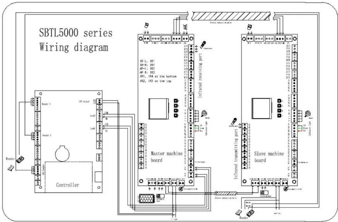
flowchart
graph TD
    subgraph Controller
        A["Controller 1"] --> B["Infrared receiving port"]
        C["Controller 2"] --> B
        B --> D["Master machine board"]
        D --> E["Slave machine board"]
    end

    subgraph Master machine board
        F["Master machine board"] --> G["Slave machine board"]
    end

    subgraph Slave machine board
        H["Slave machine board"] --> I["Slave machine board"]
    end

    J["Infrared receiving port"] --> K["Master machine board"]
    L["Slave machine board"] --> M["Slave machine board"]
    N["Infrared receiving port"] --> O["Master machine board"]
    P["Slave machine board"] --> Q["Slave machine board"]
    R["Infrared receiving port"] --> S["Master machine board"]
    T["Slave machine board"] --> U["Slave machine board"]
    V["Infrared receiving port"] --> W["Master machine board"]
    X["Slave machine board"] --> Y["Slave machine board"]
Figure 3-2
2) Functions of terminals at each zone:
System power input: The mains voltage is changed by a transformer to 24V and supplied to the master panel.
Firefighting board: After a power outage, the swing barrier of the machine is opened with power from the backup battery and is no longer closed.
Right open (DOWN button), left open (UP button): Controls the barrier to open to left or right side.
Access control power supply: Supplies power for the access board.
RS485 communication port: Receiving external signals.
Master/slave terminal: It is connected to the master and slave boards to transfer signals.
Electromagnetic clutch: It is connected to the electromagnet inside the core component to prevent collision and pinch.
Connecting cable of the motor: It is connected to the motor and supplies power to the motor.
Left infrared detector, left anti-pinch/right infrared detector, right anti-pinch detector: It detects the position of a pedestrian in the passage. It has the detecting and anti-pinch function.
Direction indicator board terminal: This terminal is connected to the LED board to indicate whether or not the pedestrian can pass through the passage.
Firefighting port: During emergencies ensuring users fast unencumbered exit to safety.
4. Troubleshooting
| Number | Failure description | Analysis and solution |
| 1 | No response from direction indicator or indication is not correct. | Check whether the connection of the roof lamp is correct or not. |
| 2 | After swiping the card there is only a swing arm action. | Check the master and slave machine type setting and the 5-core, 2-core connection line. |
| 3 | Barrier open after a long time no closing. | Check whether the time of the opening is too long or the IR sensor is covered by others. |
| 4 | Motor doesn’t rotating or the resistance too great or belt loosen. | If the motor working properly, but the rotated angle not enough, which may caused by belt loosen. If can’t solve it, try to increase the value of twelfth menu. |
| 5 | When power on, the swing arm can’t turn back to the initial position | Ensure that no obstacle in the passway, then restart the equipment. |
5. Product Maintenance
5.1 Chassis maintenance
The chassis is made up of 304 stainless steels. There may be rust stains on its surface after being used for a long time. Regularly sand the surface along the grain softly and carefully. Coat the surface with anti-rust oil, do not cover the infrared sensor.
5.2 Movement maintenance
Cut off power supply before maintenance. Open the door, clean surface dust, apply butter to the transmission mechanism. Check whether the belt is loose, if found loose, adjust the position of the motor to make the belt tight. Check and tighten others connection parts.
5.3 Power maintenance
Cut off power supply before maintenance. Check whether the plug is loose, if found loose, tight it. Do not replace the connection position at random. Check whether the external power supply is exposed, timely wrap it. Whether there is any leakage, do timely treatment. Check if the technical parameters of interface is normal, the aged electronic components should be replaced.
(Attention: Above swing barrier maintenance must be maintained by professional personnel. Especially the movement and the electric control part, first cut off the power supply, ensure the operation safety.
ZK Building, Wuhe Road, Gangtou, Bantian, Buji Town, Longgang District, Shenzhen China 518129
Tel: +86 755-89602345
Fax: +86 755-89602394
www.zkteco.com

- Content
- Product Introduction
- Model number and access control
- Chassis design and dimensions
- Mechanical system of the swing barrier
- Electronic control system
- The working principle of swing barrier
- System composition of the product
- Working modes of the system
- Specification
- Installation of the Product
- Installation notes
- Installation position of the swing barrier
- Cables installation and fixing
- Menu Introduction
- Function introduction
- 3) Operation and instruction of menu
- Menu introduction
- Device mode (Press 'ENT' to modify)
- Motor running time (Press 'ENT' to modify)
- Open duration (Press 'ENT' to modify)
- Opening mode (Press 'ENT' to modify)
- False direction entry (Press 'ENT' to modify)
- Anti-tailgate (Press 'ENT' to modify)
- Barrier position setting (Press 'ENT' to modify)
- Language setting (Press 'ENT' to modify)
- 0—简体中文
- Speed of gates (Press 'ENT' to modify)
- IR anti-pinch setting (Press 'ENT' to modify)
- Memory function (Press 'ENT' to modify)
- Min speed compensation (Press 'ENT' to modify)
- Type setting (Press 'ENT' to modify)
- Delay closing gates time setting (Press 'ENT' to modify)
- Brake starting angle (Press 'ENT' to modify)
- Unlock brake method (Press 'ENT' to modify)
- Firefighting signal setting (Press 'ENT' to modify)
- System working mode (Press 'ENT' to modify)
- Volume setting (Press 'ENT' to modify)
- Functions introduction of wiring and terminal
- 1) Wiring diagram
- 2) Functions of terminals at each zone:
- Troubleshooting
- Product Maintenance
- Chassis maintenance
- Movement maintenance
- Power maintenance
Brand : ZKTeco
Model : SBTL5200
Category : Access Control