
C2-260 - Access Control ZKTeco - Free user manual and instructions
Find the device manual for free C2-260 ZKTeco in PDF.


| Product Type | Access Control Panel |
| Brand | ZKTeco |
| Model | C2-260 |
| Processor | High-speed 32-bit 1.0GHz CPU |
| RAM | 64 MB |
| Operating System | Embedded Linux |
| Door Control | Two-door one-way/two-way |
| User Capacity | 30,000 |
| Event Record Capacity | 200,000 offline events |
| Communication | Ethernet (TCP/IP) and RS485 |
| Reader Support | RS485 and Wiegand (via WR485) |
| Relay Output (Lock) | Max 36V DC, 5A |
| Relay Output (Auxiliary) | Max 36V DC, 2A |
| Power Supply | 12V DC ±20%, ≥3A |
| Dimensions | 116.5 mm x 96.5 mm x 31.3 mm |
| Operating Temperature | -10°C to 50°C |
| Humidity | 20% to 80% |
| Protection | Over-current, over-voltage, inverse-voltage, instant over-voltage for I/O and communication ports |
| Built-in Watchdog | Yes |
| Indicators | Power (red), Run (green), COMM (yellow) |
| Installation | Rail or wall mount |
| Software | ZKBioAccess for management |
| Web Interface | ZKPanelWeb for configuration |
| Warranty | Refer to contract conditions |
Frequently Asked Questions - C2-260 ZKTeco
User questions about C2-260 ZKTeco
0 question about this device. Answer the ones you know or ask your own.
Ask a new question about this device
Download the instructions for your Access Control in PDF format for free! Find your manual C2-260 - ZKTeco and take your electronic device back in hand. On this page are published all the documents necessary for the use of your device. C2-260 by ZKTeco.
USER MANUAL C2-260 ZKTeco
C2-260 Access Control Panel
Date: January 2021
Doc Version: 1.1
English
Thank you for choosing our product. Please read the instructions carefully before operation. Follow these instructions to ensure that the product is functioning properly. The images shown in this manual are for illustrative purposes only.

For further details, please visit our Company's website
www.zkteco.eu
Copyright © 2021 ZKTECO CO., LTD. All rights reserved.
Without the prior written consent of ZKTeco, no portion of this manual can be copied or forwarded in any way or form. All parts of this manual belong to ZKTeco and its subsidiaries (hereinafter the "Company" or "ZKTeco").
Trademark
ZKTeco is a registered trademark of ZKTeco. Other trademarks involved in this manual are owned by their respective owners.
Disclaimer
This manual contains information on the operation and maintenance of the ZKTeco equipment. The copyright in all the documents, drawings, etc. in relation to the ZKTeco supplied equipment vests in and is the property of ZKTeco. The contents hereof should not be used or shared by the receiver with any third party without express written permission of ZKTeco.
The contents of this manual must be read as a whole before starting the operation and maintenance of the supplied equipment. If any of the content(s) of the manual seems unclear or incomplete, please contact ZKTeco before starting the operation and maintenance of the said equipment.
It is an essential pre-requisite for the satisfactory operation and maintenance that the operating and maintenance personnel are fully familiar with the design and that the said personnel have received thorough training in operating and maintaining the machine/unit/equipment. It is further essential for the safe operation of the machine/unit/equipment that personnel has read, understood and followed the safety instructions contained in the manual.
In case of any conflict between terms and conditions of this manual and the contract specifications, drawings, instruction sheets or any other contract-related documents, the contract conditions/documents shall prevail. The contract specific conditions/documents shall apply in priority.
ZKTeco offers no warranty, guarantee or representation regarding the completeness of any information contained in this manual or any of the amendments made thereto. ZKTeco does not extend the warranty of any kind, including, without limitation, any warranty of design, merchantability or fitness for a particular purpose.
ZKTeco does not assume responsibility for any errors or omissions in the information or documents which are referenced by or linked to this manual. The entire risk as to the results and performance obtained from using the information is assumed by the user.
ZKTeco in no event shall be liable to the user or any third party for any incidental, consequential, indirect, special, or exemplary damages, including, without limitation, loss of business, loss of profits, business interruption, loss of business information or any pecuniary loss, arising out of, in connection with, or
relating to the use of the information contained in or referenced by this manual, even if ZKTeco has been advised of the possibility of such damages.
This manual and the information contained therein may include technical, other inaccuracies or typographical errors. ZKTeco periodically changes the information herein which will be incorporated into new additions/amendments to the manual. ZKTeco reserves the right to add, delete, amend or modify the information contained in the manual from time to time in the form of circulars, letters, notes, etc. for better operation and safety of the machine/unit/equipment. The said additions or amendments are meant for improvement /better operations of the machine/unit/equipment and such amendments shall not give any right to claim any compensation or damages under any circumstances.
ZKTeco shall in no way be responsible (i) in case the machine/unit/equipment malfunctions due to any non-compliance of the instructions contained in this manual (ii) in case of operation of the machine/unit/equipment beyond the rate limits (iii) in case of operation of the machine and equipment in conditions different from the prescribed conditions of the manual.
The product will be updated from time to time without prior notice. The latest operation procedures and relevant documents are available on http://www.zkteco.com
If there is any issue related to the product, please contact us.
ZKTeco Europe
For business-related queries, please write to us at sales@zkteco.eu
To know more about our global branches, visit www.zkteco.eu
About the Company
ZKTeco is one of the world's largest manufacturer of RFID and Biometric (Fingerprint, Facial, Finger-vein) readers. Product offerings include Access Control readers and panels, Near & Far-range Facial Recognition Cameras, Elevator/floor access controllers, Turnstiles, License Plate Recognition (LPR) gate controllers and Consumer products including battery-operated fingerprint and face-reader Door Locks. Our security solutions are multi-lingual and localized in over 18 different languages. At the ZKTeco state-of-the-art 700,000 square foot ISO9001-certified manufacturing facility, we control manufacturing, product design, component assembly, and logistics/shipping, all under one roof.
The founders of ZKTeco have been determined for independent research and development of biometric verification procedures and the productization of biometric verification SDK, which was initially widely applied in PC security and identity authentication fields. With the continuous enhancement of the development and plenty of market applications, the team has gradually constructed an identity authentication ecosystem and smart security ecosystem, which are based on biometric verification techniques. With years of experience in the industrialization of biometric verifications, ZKTeco was officially established in 2007 and now has been one of the globally leading enterprises in the biometric verification industry owning various patents and being selected as the National High-tech Enterprise for 6 consecutive years. Its products are protected by intellectual property rights.
About the Manual
This manual introduces the operations of the C2-260 Access Control Panel.
All figures displayed are for illustration purposes only. Figures in this manual may not be exactly consistent with the actual products.
Document Conventions
Conventions used in this manual are listed below:
GUI Conventions
| For Software | |
| Convention Description | |
| Bold font | Used to identify software interface names e.g. OK, Confirm, Cancel |
| > | Multi-level menus are separated by these brackets. For example, File > Create > Folder. |
| For Device | |
| Convention Description | |
| <> | Button or key names for devices. For example, press |
| [] | Window names, menu items, data table, and field names are inside square brackets. For example, pop up the [New User] window |
| / | Multi-level menus are separated by forwarding slashes. For example, [File/Create/Folder]. |
Symbols
| Convention Description | |
 | This implies about the notice or pays attention to, in the manual |
| [HWSX] | The general information which helps in performing the operations faster |
 | The information which is significant |
| [AKBD] | Care taken to avoid danger or mistakes |
 | The statement or event that warns of something or that serves as a cautionary example. |
Table of Contents
1 SAFETY INSTRUCTIONS......6
1.1 IMPORTANT SECURITY INSTRUCTIONS....6
1.2 INSTALLATION INSTRUCTIONS....7
2 SYSTEM INTRODUCTION....9
2.1 SYSTEM FUNCTIONAL PARAMETERS....9
2.2 PRODUCT TECHNICAL PARAMETERS 9
2.3 CONTROL PANEL INDICATORS....9
3 INSTALLATION AND CONNECTION ....11
3.1 INSTALLATION PROCEDURE 11
3.2 INSTALLATION OF ACCESS CONTROL PANEL WIRES....12
3.3 CONTROL PANEL SYSTEM INSTALLATION....13
3.4 CONTROL PANEL CONNECTION TERMINALS 14
3.5 CONNECTION WITH DOOR SENSORS, EXIT SWITCHES, AUXILIARY INPUT DEVICES, AND RS485 EXTENSION COMMUNICATION ....15
3.6 CONNECTION WITH RS485/WIEGAND READERS....18
3.7 RELAY OUTPUT CONNECTION....20
4 EQUIPMENT COMMUNICATION 22
4.1 ACCESS CONTROL NETWORKING WIRES AND WIRING 22
4.2 TCP/IP COMMUNICATION....23
4.3 ZKPANELWEB 23
5 ZKBIOACCESS....28
5.1 LOGIN....28
5.2 ACTIVATE THE SYSTEM 28
5.3 MODIFY PASSWORD....28
5.4 DEVICE....29
5.4.1 ADDING A DEVICE....30
5.4.2 I/O BOARD....34
5.4.3 DEVICE OPERATION....35
5.5 ADD A USER AND A CARD 42
5.6 ACCESS CONTROL SETTINGS 47
5.7 REAL-TIME MONITORING 47
5.8 REPORTS 51
APPENDIX 1....53 OPERATING DEMONSTRATION OF CONNECTING C2-260, WR485 AND WIEGAND READER....53
APPENDIX 2....58
1 Safety Instructions
1.1 Important Security Instructions
- Read and follow the instructions carefully before operation. Please keep the instructions for future reference.
- Accessories: Please use the accessories recommended by the manufacturer or delivered with the product. Other accessories are not recommended, including major alarming systems and monitoring systems. The primary alarming and monitoring system should comply with the local applicable fire-prevention and security standards.
- Installation cautions: Do not place this equipment on an unstable table, tripod mount, support, or base, lest the equipment falls and get damaged or any other undesirable outcome resulting in severe personal injuries. Therefore, it is essential to install the equipment as instructed by the manufacturer.
- All peripheral devices must be grounded.
- No external connection wires can be exposed. All the connections and idle wire ends must be wrapped with insulating tapes to prevent any damage to the equipment by accidental contact of the exposed wires.
- Repair: Do not attempt to have an unauthorized repair of the equipment. Disassembly or detachment is risky and likely to cause shock. All repairs should be done by a qualified technician.
- If any of the following cases arise, disconnect the power supply from the equipment first and intimate the technician immediately.
The power cord or connector is damaged.
Any liquid or material spilled into the equipment.
The equipment is wet or exposed to bad weather (rain, snow, etc.).
If the equipment cannot work properly, even if it is operated as instructed, please be sure to adjust only the control components specified in the operating instructions. Incorrect adjustments on other control components may cause damage to the equipment; even the equipment may fail to operate permanently.
The equipment falls, or its performance changes dramatically.
-
Replacing components: If it is necessary to replace a component, only the authorized technician can replace the accessories specified by the manufacturer.
-
Security inspection: After the equipment is repaired, the technician must conduct security inspection to ensure proper working of the equipment.
-
Power supply: Operate the equipment with only the type of power supply indicated on the label. Contact the technician for any uncertainty about the type of power supply.
i Violation of any of the following cautions is likely to result in personal injury or equipment failure. We will not be responsible for the damages or injuries caused thereby.
- Before installation, switch off the external circuit (that supplies power to the system), including locks.
- Before connecting the equipment to the power supply, ensure the output voltage is within the specified range.
- Never connect the power before completion of installation.
1.2 Installation Instructions
- The conduits of wires under relay must match with the metal conduits; other wires can use PVC conduits, to prevent failure caused by rodent damage. The Control panel is designed with proper antistatic, lightning-proof, and leakage-proof functions, ensure its chassis and the AC ground wire are correctly connected and the AC ground wire is grounded physically.
- It is recommended not to plug/unplug connection terminals frequently when the system is powered on. Be sure to unplug the connection terminals before starting any relevant welding job.
- Do not detach or replace any control panel chip without permission, and an unpermitted operation may cause damage to the control panel.
- It is recommended not to connect any other auxiliary devices without permission. All non-routine operations must be communicated to our engineers in advance.
- A control panel should not share the same power socket with any other large-current device.
- It is preferable to install card readers and buttons at the height of 1.4 to 1.5m above the ground or subject to customers' usual practice for proper adjustment.
- It is advised to install control panels at places where maintenance is easy, like a weak electric well.
- It is strongly recommended that the exposed part of any connection terminal should not be longer than 4mm, and specialized clamping tools may be used to avoid short-circuit or communication failure resulting from accidental contact with excessively exposed wires.
- To save access control event records, export the data periodically from control panels.
-
Prepare countermeasures according to application scenarios for unexpected power failure, like selecting power supply with UPS.
-
If RS485 reader is connected externally and shared the power supply with the device (The control panel does not support fingerprint verification of RS485 reader), it is recommended that the connection between the RS485 reader port and the reader be no longer than 100m. Otherwise, it is recommended that the reader use a separate power supply.
- To protect the access control system against the self-induced electromotive force generated by an electronic lock at the instant of switching off/on, it is necessary to connect a diode in parallel (please use the FR107 delivered with the system) with the electronic lock to release the self-induced electromotive force during onsite connection for application of the access control system.
- It is recommended that an electronic lock and a control panel should use separate power supplies.
- It is recommended to use the power supply delivered with the system as the control panel power supply.
- In a place with substantial magnetic interference, galvanized steel pipes or shielded cables are recommended, and proper grounding is required.
2 System Introduction
The Access Control management system is a new modernized security management system, which is an effective measure of security and protection management. It is mainly used to manage the entrances and exits of highly secured places, such as banks, hotels, equipment rooms, offices, smart communities, and factories.
2.1 System Functional Parameters
• High-speed 32-bit 1.0GHz CPU and 64M RAM.
• Embedded LINUX operating system.
• Two-door one-way/two-way.
• User capacity: 30,000.
• A maximum of 30,000 cardholders.
• 200,000 offline event records.
• Use Ethernet communication technologies for reliable communications.
• Control Panel with a watchdog (hardware) built in to prevent a crash.
- Over-current, over-voltage, and inverse-voltage protection for the input of the power supply to the control panel.
• Over-current protection for the power supply to card readers.
- Instant over-voltage protection for all input/output ports.
- Instant over-voltage protection for communication ports.
2.2 Product Technical Parameters
• Working Power supply: Rated voltage 12V ( ± 20%) DC, rated current is ≥ 3A
• Working environment: Temperature -10°C to 50°C; Humidity 20% to 80%.
- Electronic lock relay output: The maximum switching voltage is 36V(DC); The maximum switching current is 5A.
- Auxiliary relay output: The maximum switching voltage is 36V(DC); The maximum switching current is 2A.
- The detachable connection terminals are made of alloy-steel non-magnetic flange materials.
• Control panel dimensions: 116.5mm*96.5mm*31.3mm
2.3 Control Panel Indicators
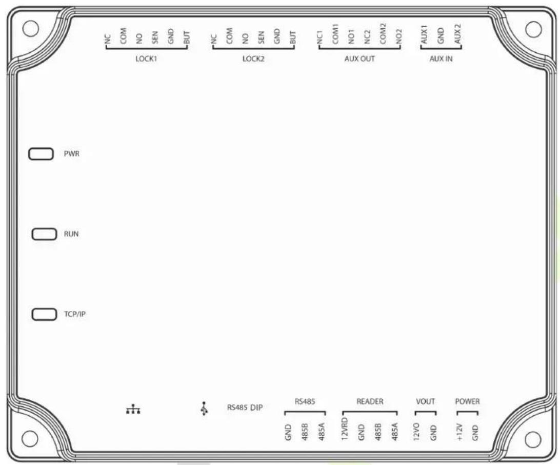
When the C2-260 is powered on, normally the POWER indicator (red) is lit constantly, the RUN indicator (green) shall flash slowly (indicating the system is normal), and other indicators are all off.
COMM indicator (yellow): It flashes when the system is communicating with other devices (e.g., PC). When the indicator is flashing continuously, it indicates data transmission. When the indicator is flashing slowly, it indicates real-time monitoring status.
Indicator Diagram:
3 Installation and Connection
3.1 Installation Procedure
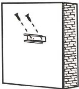
The following describes the rail installation process.
natural_image
Diagram showing a spray gun interacting with a brick wall, no text or symbols present1) Fix the guide rail on the wall
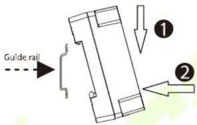
2) Fix the device to the guide rail.
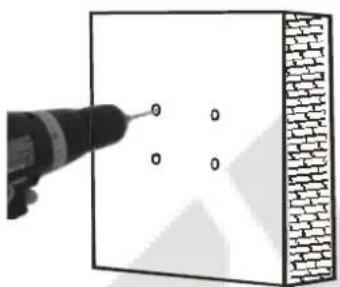
The following describes the wall installation process.
natural_image
Diagram showing a drill bit interacting with a brick wall, no text or symbols present1) Drill holes on the wall
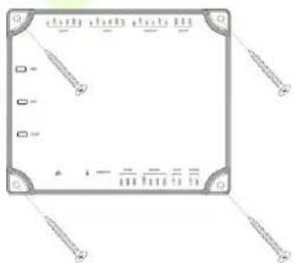
2) Fix the device with four screws
3.2 Installation of Access Control Panel Wires
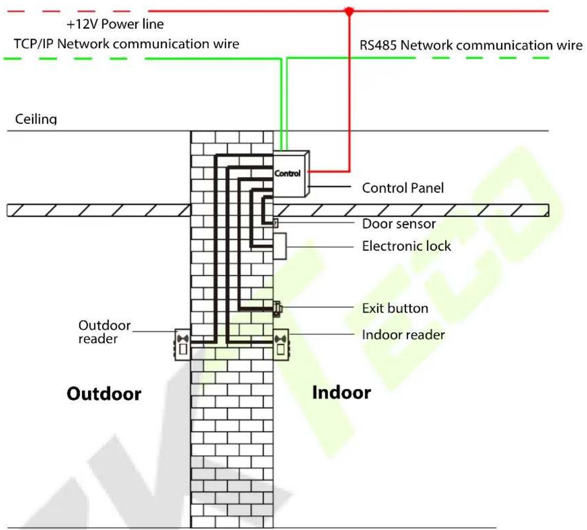
Access Control Panel Wire Installation Diagram
Remarks:
- Ensure the power supply is disconnected before connecting the wires; otherwise, it may cause severe damage to the equipment.
- The access control wires must be separated according to heavy and light current; the control panel wires, electronic lock wires, and exit button wires must run through their casing pipes, respectively.
3.3 Control Panel System Installation
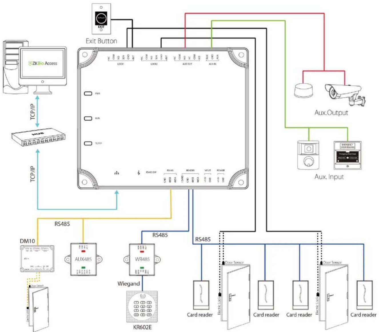
Schematic Diagram of System Installation
The access control management system consists of two parts: Management Workstation (PC) and Control panel. The management workstation and control panel communicate through TCP/IP and RS485 network. The communication wires should be kept away from high-voltage wires as far as possible and should be neither routed in parallel with nor bundled with power wires.
A management workstation is a PC connected with the network. By running the access control management software installed in the PC, access control management personnel can remotely perform various management functions, like adding/deleting a user, viewing event records, opening/closing doors, and monitoring the status of each door in real-time.
3.4 Control Panel Connection Terminals
C2-260 Terminal connection diagram
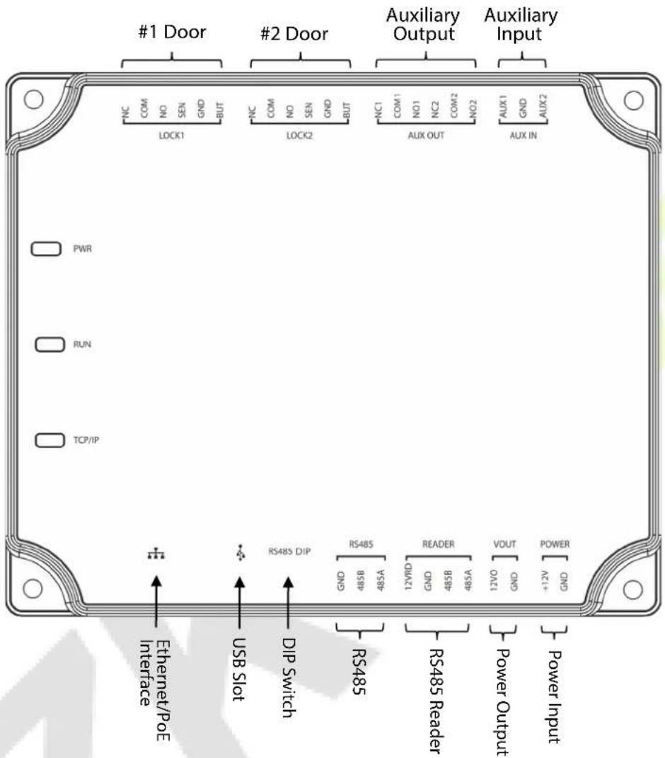
• Description of the terminals:
- The auxiliary input may connect to infrared body detectors, fire alarms, or smoke detectors.
- The auxiliary output may connect to alarms, cameras or doorbells, etc.
- PC RS485 indicates the RS485 cable is connected to the DM10/AUX485 through this port. The RS485 Reader port can be connected externally to RS485 reader.
- Restore factory setting: The NO.4 of DIP switch is OFF by default. When it is moved up and down for three times within 5 seconds and finally returned to ON position, the factory settings will be restored after the access control panel is restarted, and the IP address will restore to the default (192.168.1.201).
- The terminals above are set through the relevant access control software. Please see the respective software manual for further details.
Ports of C2-260 Control Panel:
| No. | Functional Port | C2-260(Two-Door Two-Way) |
| 1 | Exit button | 2 |
| 2 | Control lock relay | 2 |
| 3 | Door Sensor | 2 |
| 4 | Auxiliary Input | 2 |
| 5 | Auxiliary Output | 2 |
| 6 | RS485 Reader | 4 |
| 7 | RS485 Extension Communication | √ |
| 8 | TCP/IP | √ |
3.5 Connection with Door Sensors, Exit Switches, Auxiliary Input Devices, and RS485 Extension Communication
1. Door sensor
A Door Sensor is used to sense the open/close status of a door. With a door sensor switch, an access control panel can detect the unauthorized opening of a door and will trigger the output of alarm. Moreover, if a door is not closed within a specified period after it is opened, the door control panel will also raise the alarm. It is recommended to select two-core wires with a gauge over 0.22 mm^2 . A door sensor can be omitted if it is unnecessary to monitor the open/closed status of a door, raise the alarm when the door is not closed for a long time, monitor if there is unauthorized access, and use the interlock function.
2. Exit switch
An exit switch is a switch installed indoor to open a door. When it is switched on, the door will be opened. An exit button is fixed at the height of about 1.4m above the ground. Ensure it is located in the right position without slant, and its connection is correct and secure. (Cut off the exposed end of any unused wire and wrap it with insulating tape.) Make sure to avoid electromagnetic interference (such as light switches and computers). It is recommended to use two-core wires with a gauge over 0.3mm^2 as the connection wire between an exit switch and the Control panel.
3. Auxiliary input
The control panel provides one auxiliary input interface which may connect to infrared body detectors, smoke detectors, gas detectors, window magnetic alarms, wireless exit switches, etc. Auxiliary inputs are set through the relevant access control software. Please see the respective software manual for further details.
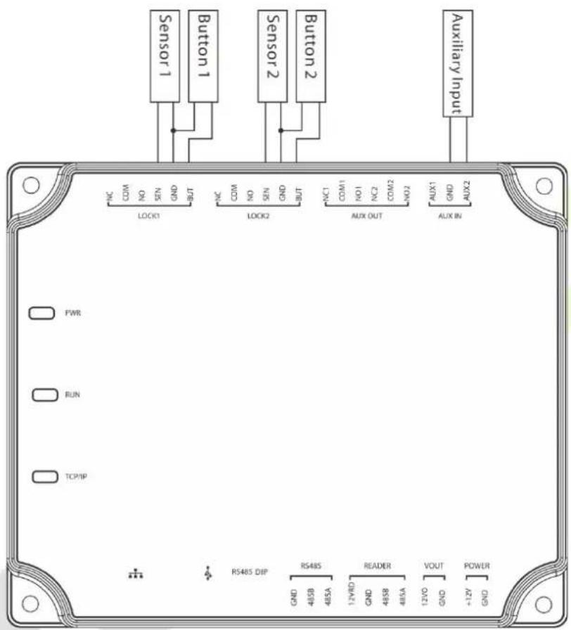
Connections between Control Panel and Door Sensors, Exit Switches and Auxiliary Input Devices
4. RS485 extension communication
The Control panel supports extensive modules which like DM10 and AUX485, through RS485. A C2-260 can connect eight DM10 at most or can connect two AUX485 at most. As shown in the following figure.
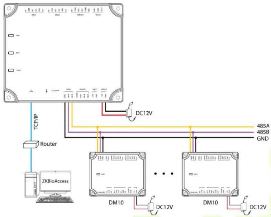
flowchart
graph TD
    A["User Interface"] -->|TCP/IP| B["Router"]
    B --> C["ZKBioAccess"]
    C --> D["DM10"]
    D --> E["DC12V"]
    E --> F["485A"]
    E --> G["485B"]
    E --> H["GND"]
    D --> I["DM10"]
    I --> J["DC12V"]
    J --> K["485A"]
    J --> L["485B"]
    J --> M["GND"]
Connect with DM10 through RS485
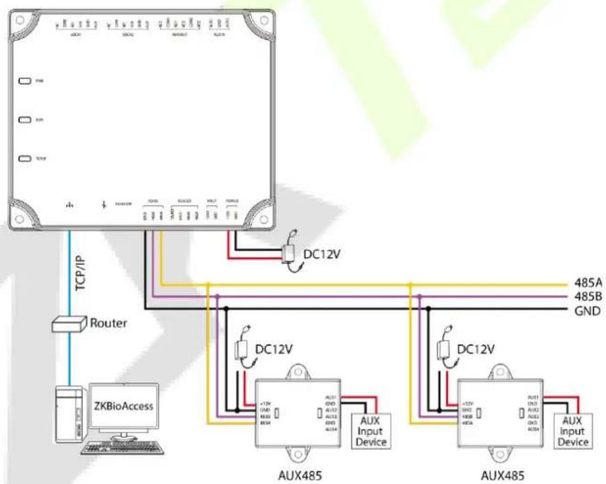
flowchart
graph TD
    A["Device"] -->|TCP/IP| B["ZKBioAccess"]
    B --> C["Router"]
    C --> D["DC12V"]
    D --> E["AUX485"]
    E --> F["DX12V"]
    F --> G["AUX485"]
    G --> H["DX12V"]
    H --> I["DX12V"]
    I --> J["DX12V"]
    J --> K["DX12V"]
    K --> L["DX12V"]
    L --> M["DX12V"]
    M --> N["DX12V"]
    N --> O["DX12V"]
    O --> P["DX12V"]
    P --> Q["DX12V"]
    Q --> R["DX12V"]
    R --> S["DX12V"]
    S --> T["DX12V"]
    T --> U["DX12V"]
    U --> V["DX12V"]
    V --> W["DX12V"]
    W --> X["DX12V"]
    X --> Y["DX12V"]
    Y --> Z["DX12V"]
    Z --> AA["DX12V"]
    AA --> AB["DX12V"]
    AB --> AC["DX12V"]
    AC --> AD["DX12V"]
    AD --> AE["DX12V"]
    AE --> AF["DX12V"]
    AF --> AG["DX12V"]
    AG --> AH["DX12V"]
    AH --> AI["DX12V"]
    AI --> AJ["DX12V"]
    AJ --> AK["DX12V"]
    AK --> AL["DX12V"]
    AL --> AM["DX12V"]
    AM --> AN["DX12V"]
    AN --> AO["DX12V"]
    AO --> AP["DX12V"]
    AP --> AQ["DX12V"]
    AQ --> AR["DX12V"]
    AR --> AS["DX12V"]
    AS --> AT["DX12V"]
    AT --> AU["DX12V"]
    AU --> AV["DX12V"]
    AV --> AW["DX12V"]
    AW --> AX["DX12V"]
    AX --> AY["DX12V"]
Connect with AUX485 through RS485
Note:
- A C2-260 can connect to maximum eight DM10 modules or two AUX485 modules.
- Each AUX485 module can connect to maximum four auxiliary devices.
- Each DM10/AUX485 module requires a separate power supply.
3.6 Connection with RS485/Wiegand Readers
The Control panel supports RS485 card reader. And it also supports Wiegand reader, through WR485.
• Connection with RS485 Readers
The Control panel supports four readers, which can be connected in the two-door two-way mode.
RS485 reader connection: Set the RS485 address (device number) of the reader by DIP switch or other ways.
| Control Panel\RS485 address | 1 2 3 | 4 | ||
| C2-260 | Door1 (In) | Door1 (Out) | Door2 (In) | Door2 (Out) |
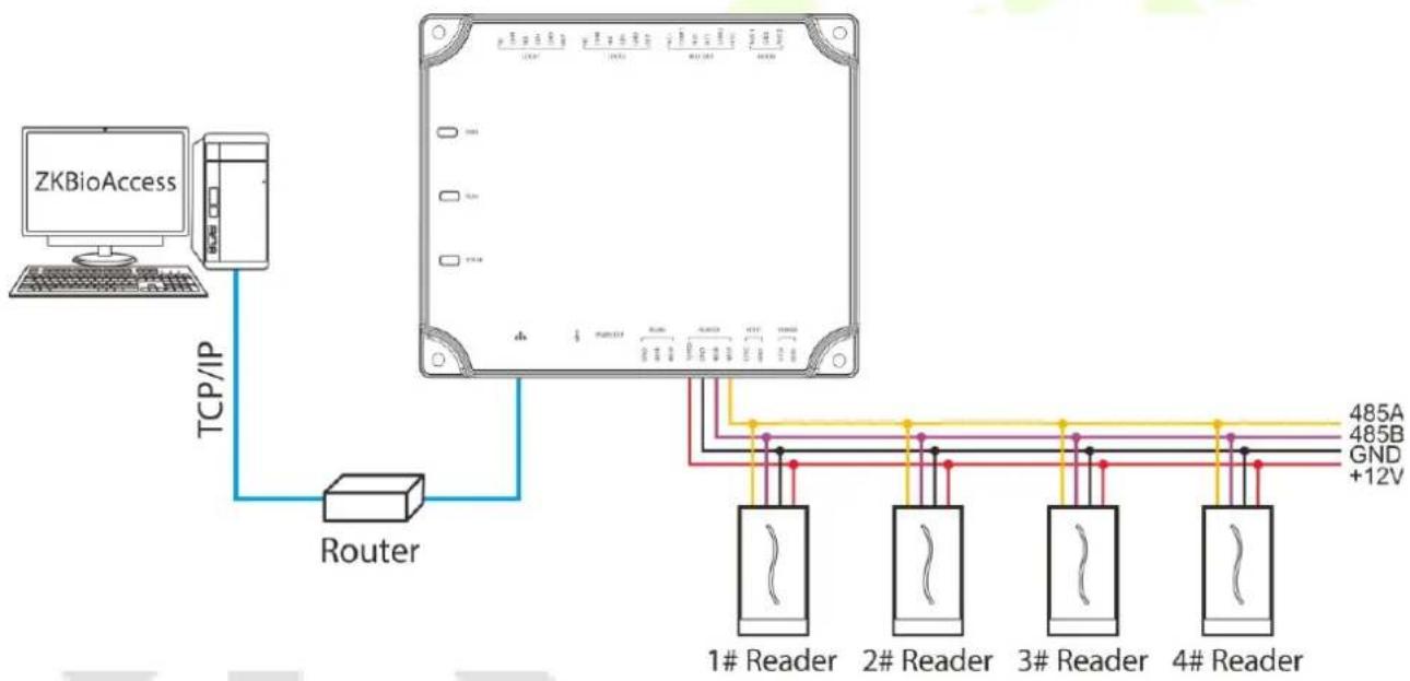
flowchart
graph TD
    A["ZKBioAccess"] -->|TCP/IP| B["Router"]
    B --> C["Server"]
    C --> D["1# Reader"]
    C --> E["2# Reader"]
    C --> F["3# Reader"]
    C --> G["4# Reader"]
    D --> H["485A"]
    E --> I["485B"]
    F --> J["GND +12V"]
The connection between the Control Panel and RS485 Card Readers
A single RS485 reader interface can supply a maximum of 750 mA (12V) current. So, the entire current consumption should be less than this maximum value when the readers share power with the panel. For calculation, please use the maximum current of the reader, and starting current is usually more than twice the standard work current.
Using the KR502M-RS card reader as an example, the standby current is less than 80mA; the maximum current is less than 90mA. When starting the device, the instantaneous current can reach 180 mA. For an RS485 reader, considered that the starting current is large, only four readers can connect to the power supply through the RS485 reader interface. So, the power of the control panel can only connect up to 2 readers.
If RS485 reader is connected externally and shares the power supply with the device, it is recommended
that the connection between the RS485 reader port and the reader be no longer than 100m. Otherwise, it is recommended to use a separate power supply for the reader.
For the devices which consume more power, we suggest using different power supplies to ensure steady operation.
• Connection with Wiegand Readers
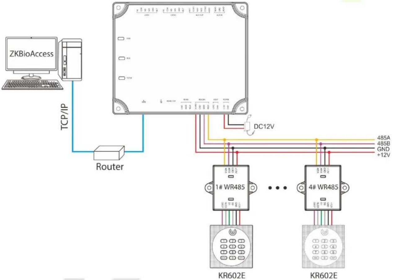
The Control panel supports the connection of Wiegand reader via WR485 module. The wiring is shown in the figure below.
flowchart
graph TD
    A["ZKBioAccess"] -->|TCP/IP| B["Router"]
    B --> C["1# WR485"]
    B --> D["4# WR485"]
    C --> E["KR602E"]
    D --> F["KR602E"]
    C --> G["DC12V"]
    D --> H["485A"]
    D --> I["485B"]
    D --> J["GND +12V"]
The connection between the Control Panel and Wiegand Readers via WR485

Notes:
A C2-260 can connect to maximum four WR485 modules.
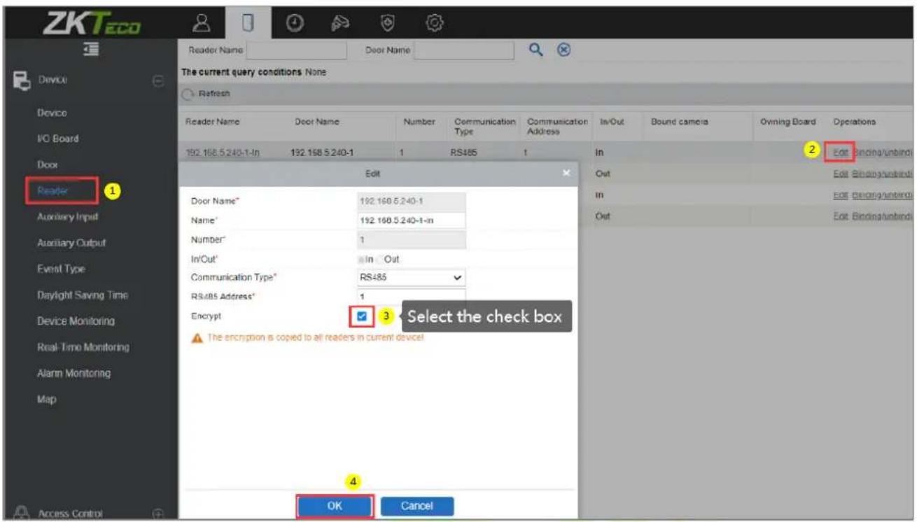
- Because the WR485 is an encryption mode, after the C2-260 control panel is added to the ZKBioAccess software, you need to set the "Encrypt" option for the Wiegand reader. So that the Wiegand reader can be used normally. As shown in the following figure.
• For further details and settings of the parameters, see Appendix 1.
3.7 Relay Output Connection
C2-260 has three relays (two used as control locks by default, and the other one used as auxiliary outputs).
The relays for auxiliary outputs may connect to monitors, alarms, doorbells, etc. Auxiliary outputs are set through the relevant access control software. Please refer to the respective software manual for details.
- The default connection mode of the door lock is "dry mode." In general, the electronic lock uses an external power supply separately. The wiring mode of the door lock relay cannot be changed, except that the auxiliary output relay. The diagram below uses the example of a door lock connection to demonstrate the output relay connection.
- An access control panel provides multiple electronic lock outputs. The COM and NO terminals apply to the locks that are unlocked when power is connected and locked when power is disconnected. The COM and NC terminals use the locks that are locked when power is connected and unlocked when power is disconnected.
- Our access control panel is powered by standard PoE or access control power. You can choose either one of the power supplies as needed. Both two power supplies provide 12V/3A power for only the power consumption of the control panel, Wiegand readers, and output power consumption of RS485 reader.
- To protect the access control system against the self-induced electromotive force generated by an electronic lock at the instant of switching off/on, it is necessary to connect a diode in parallel (please use FR107 delivered with the system) with the electronic lock to release the self-induced electromotive force during the onsite connection for application of the access control system.
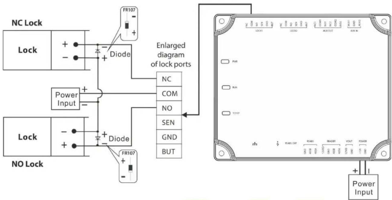
Wiring diagram of lock connection
4 Equipment Communication
The background PC software can communicate with the system according to two protocols (TCP/IP and RS485) for data exchange and remote management.
4.1 Access Control Networking Wires and Wiring
- The power supply is 12V DC converted from 220V or PoE.
- As an electronic lock has a large current, it generates a strong interference signal while functioning. To reduce such an effect, 4-core wires (RVVP 4 × 0.75mm^2 , two for a power supply, and two for a door sensor) are recommended.
- "RS485" interface uses 4-core communication shielded wires (RVVSP 4*0.5mm).
- Other control cables (like exit switches) are all made of 2-core wires (RVVSP 2 × 0.5mm^2 ).
- Notes for wiring:
Signal wires (like network cables) can neither run in parallel with nor share one casing pipe with large-power electric wires (like electronic lock wires and power cables). If parallel wiring is unavoidable for environmental reasons, the distance must be above 50cm.
Try to avoid using any conductor with a connector during distribution. When a connector is indispensable, it must be crimped or welded. No mechanical force can be applied to the joint or branch of conductors.
In a building, the distribution lines must be installed horizontally or vertically. They should be protected in casing pipes (like plastic or iron water pipes, to be selected according to the technical requirements of the indoor distribution). Metal hoses are applicable to ceiling wiring, but they must be secure and good-looking.
Shielding measures and shielding connection: If the electromagnetic interference in the wiring environment is found substantial in the survey before construction, it is necessary to consider the shielding protection of data cables when designing a construction scheme. Overall, shielding protection is required if there is a large radioactive interference source or wiring has to be parallel with a large-current power supply on the construction site. Generally, shielding measures includes keeping a maximum distance from any interference source, and using metal wiring troughs or galvanized metal water pipes to ensure reliable grounding of the connection between the shielding layers of data cables and the metal troughs or pipes. Noted that a shielding enclosure can have a shielding effect only when it is grounded reliably.
Ground wire connection method: Reliable large-diameter ground wires in compliance with applicable national standards are needed on the wiring site and should be connected in a tree form to avoid DC loop. These ground wires must be kept far away from lightning fields. No lightning conductor can serve as a ground wire and ensure there is no lightning current through any ground wire when there is lightning. Metal wiring troughs and pipes must be connected
continuously and reliably and linked to ground wires through large-diameter cables. The impedance of this section of wire cannot exceed 2 ohms. Also, the shielding layer must be connected reliably and grounded at one end to guarantee a uniform current direction. The ground wire of the shielding layer must be connected through a large-diameter wire (not less than 2.5mm^2 ).
4.2 TCP/IP Communication
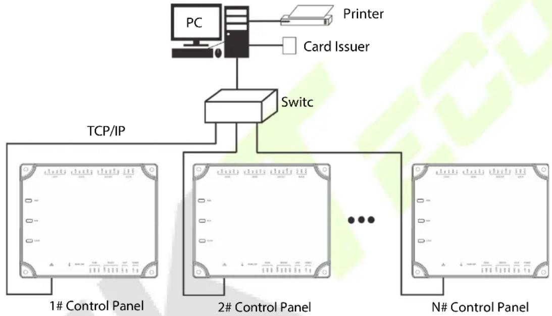
The Ethernet 10/100Base-T Crossover Cable, a type of crossover network cable, is mainly used for cascading hubs and switches or used to connect two Ethernet endpoints directly (without a hub). Both 10Base-T and 100Base-T are supported.
flowchart
graph TD
    PC["PC"] --> Switch["Switch"]
    Switch --> PC_Protter["Printer"]
    Switch --> Switch_Card["Card Issuer"]
    Switch_Card --> PC_Protter
    Switch_Card --> PC_N#ControlPanel["N# Control Panel"]
    Switch_Card --> TCP/IP["TCP/IP"]
    Switch_Card --> TCP/IP_Protter1["1# Control Panel"]
    Switch_Card --> TCP/IP_Protter2["2# Control Panel"]
    Switch_Card --> TCP/IP_N#ControlPanel["N# Control Panel"]
TCP/IP Communication System Networking
In Access software: Click Device > Search Device to search for access controllers in the network, and directly add from the search result.
ZKPanelWeb 4.3
This built-in function is newly added to assist user to manage controllers more conveniently. Users can use the Web Server function to perform operations, such as network configuration, push communication configuration, time synchronization, and user account management.
Log on to the Web Server
Create a valid connection string using TCP/IP.
Input the IP address of the controller (factory default is 192.168.1.201) in the address bar; enter the user name and password (both are admin), and click [Sign In] to access the ZKPanelWeb.
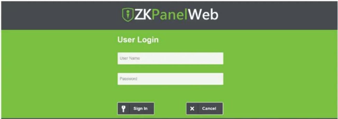
Note:
- IP addresses of both the server (PC) and the controller must be in the same network segment.
- IP address of the controller could be found by searching devices with the BioSecurity software ([Access] > [Access Device] > [Device] > [Search Device]).
- TCP/IP Settings
Click [TCP/IP Settings] to modify the IP address and gateway address.
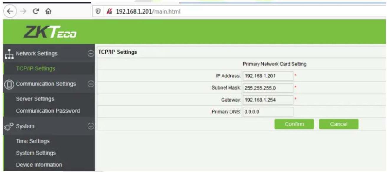
• Communication Settings
Set communication parameters in ZKPanelWeb and connect the controller to the server (PC); the controller will automatically push information to the server.
1) Server Settings
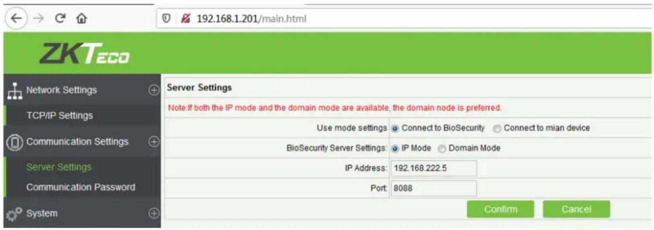
Use mode settings: The default mode is Connect to BioSecurity.
BioSecurity Server Settings: To set the parameters of the IP Mode and Domain Mode.
IP Mode: The default server IP is 0.0.0.0, and you can modify it according to the practical situation.
Port: The default Port is 8088, and you can modify it according to the practical situation.
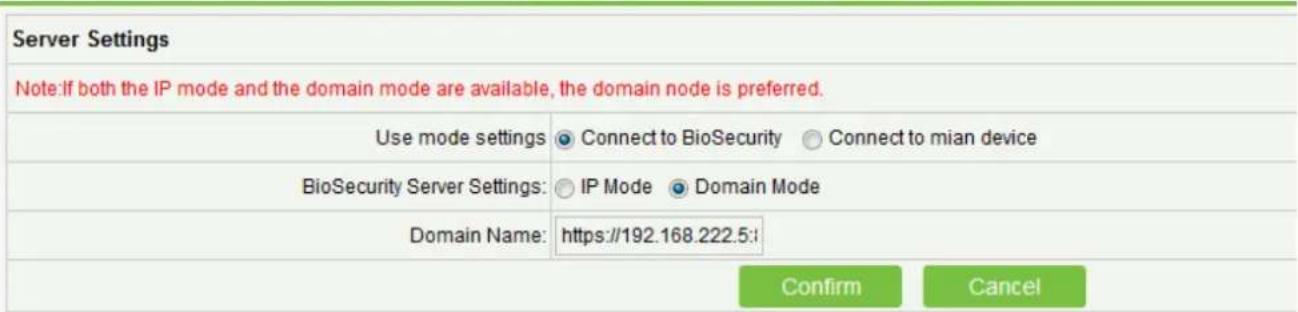
Domain Mode: The default value is null, and you can set its value. If the user wants to login to the BioSecurity software via HTTPS, then set the domain name here. The format is: https://192.168.222.5:8088.
2) Communication Password
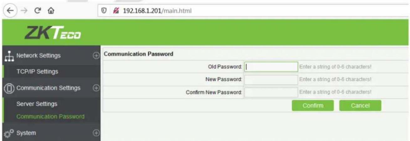
Communication Password: Indicates that network communication is encrypted. The default value is null, and you can set its value.
If you configure the communication password here, the same communication password must be configured on the server before the connection can be set up.
System
The user can synchronize time to the computer, set up the system and view device information here.
1) Time Settings
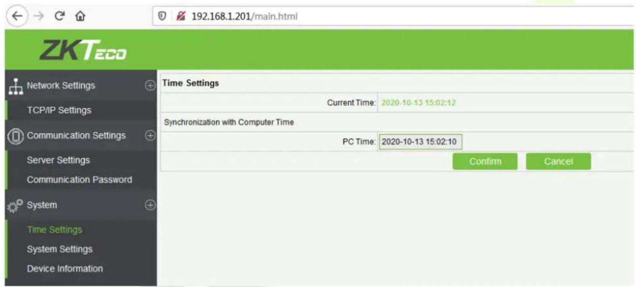
2) System Settings
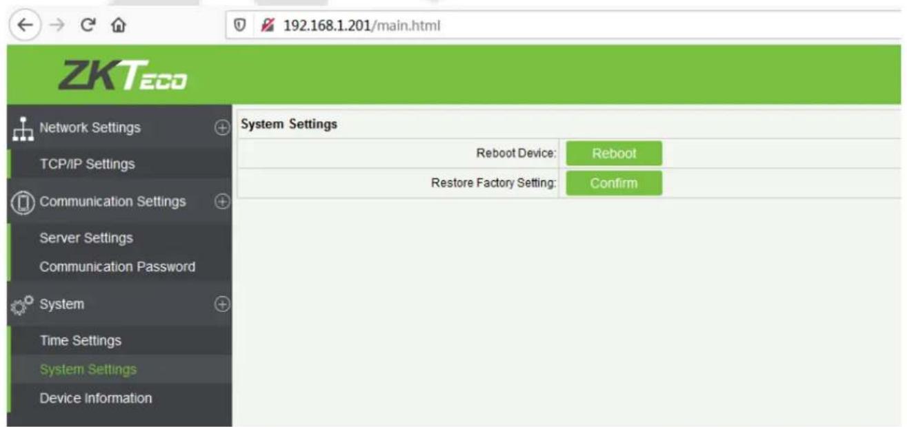
3) Device Information
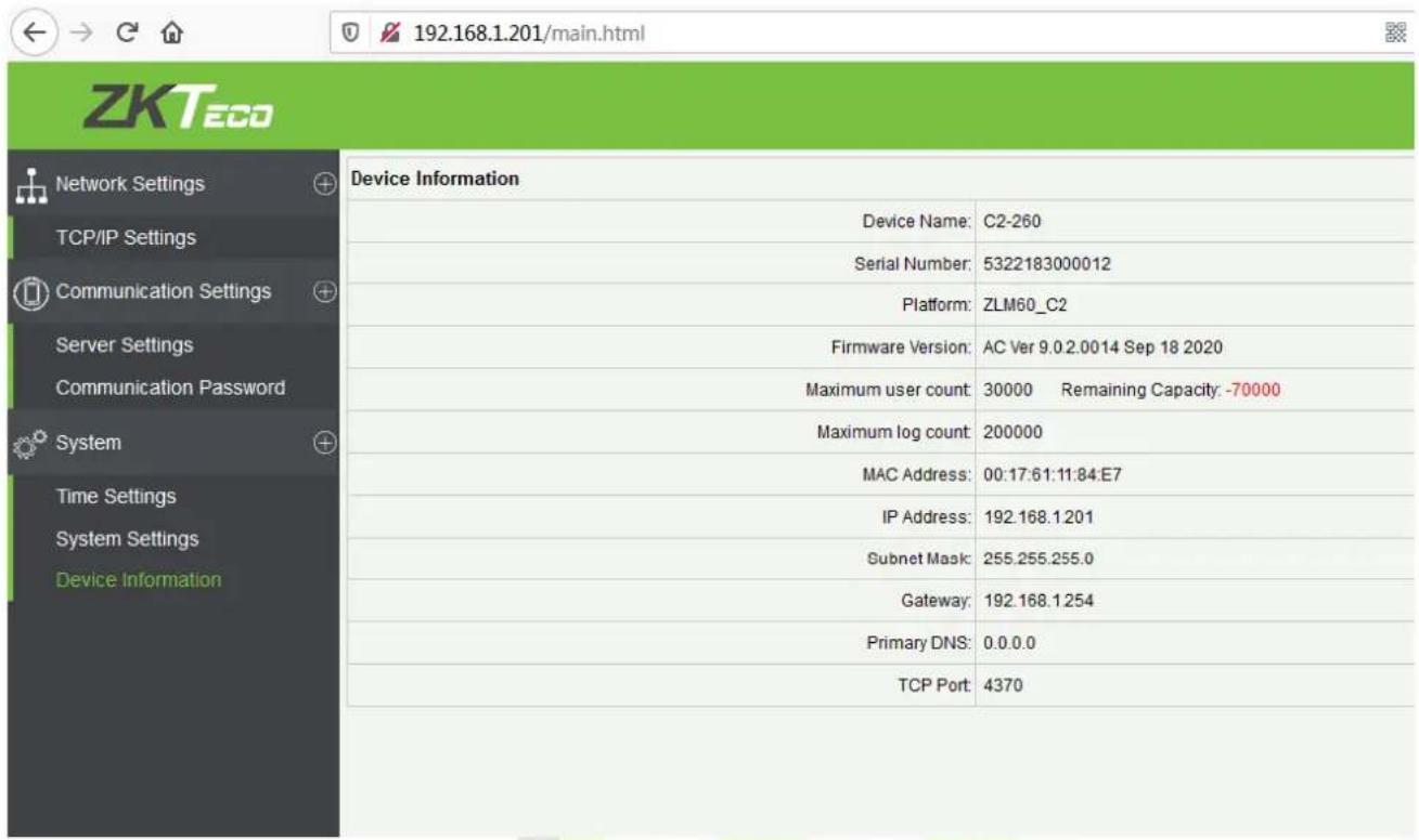
5 ZKBioAccess
The following sections explain the functions of ZKBioAccess software after the Access Controllers are installed.
Login 5.1
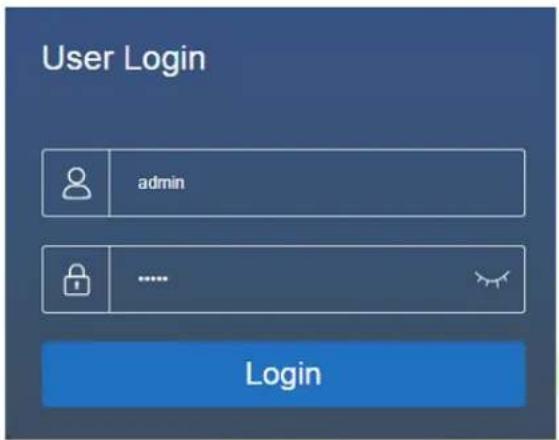
After installing the software, double-click the ZKBio Access icon to open the software. You may also open the recommended browser and enter the IP address and server port in the address bar. The IP address is http://127.0.0.1:8098 by default.
If the software is not installed in your server, you may enter the IP address and server port in the address bar.

Note: The username of the superuser is admin, and the password is admin, then click Login. After logging in for the first time, you need to reset your password.
5.2 Activate the System
Please refer to the corresponding license activation document.
Modify Password 5.3
You can modify the login password in the Personal Information section.
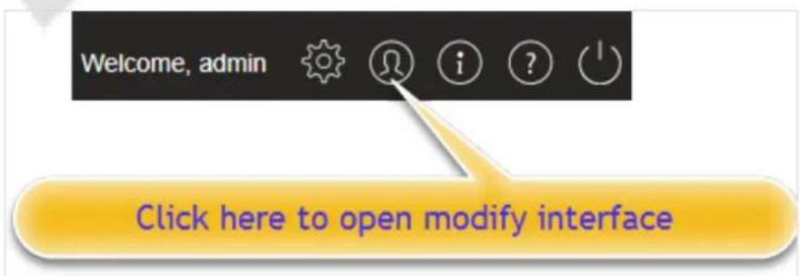
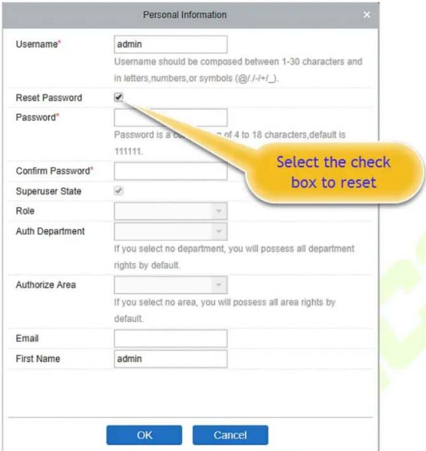
Select the Reset Password checkbox to modify the password.

Note: Both the Superuser and the new user are created by the Superuser (the default password for
the new users is 111111). The username is not case-insensitive, but the password is case-sensitive.
Device 5.4
The Device Settings adds an access device and then sets the communication parameters of the connected devices, including system settings and device settings. When the communication is successful, you can view here the information of the connected devices, and perform remote monitoring, uploading and downloading, etc.
5.4.1 Adding a Device
There are two ways to add Access Devices.
Add Device by Searching Access Controllers.
Search the Access Controllers in the Ethernet.
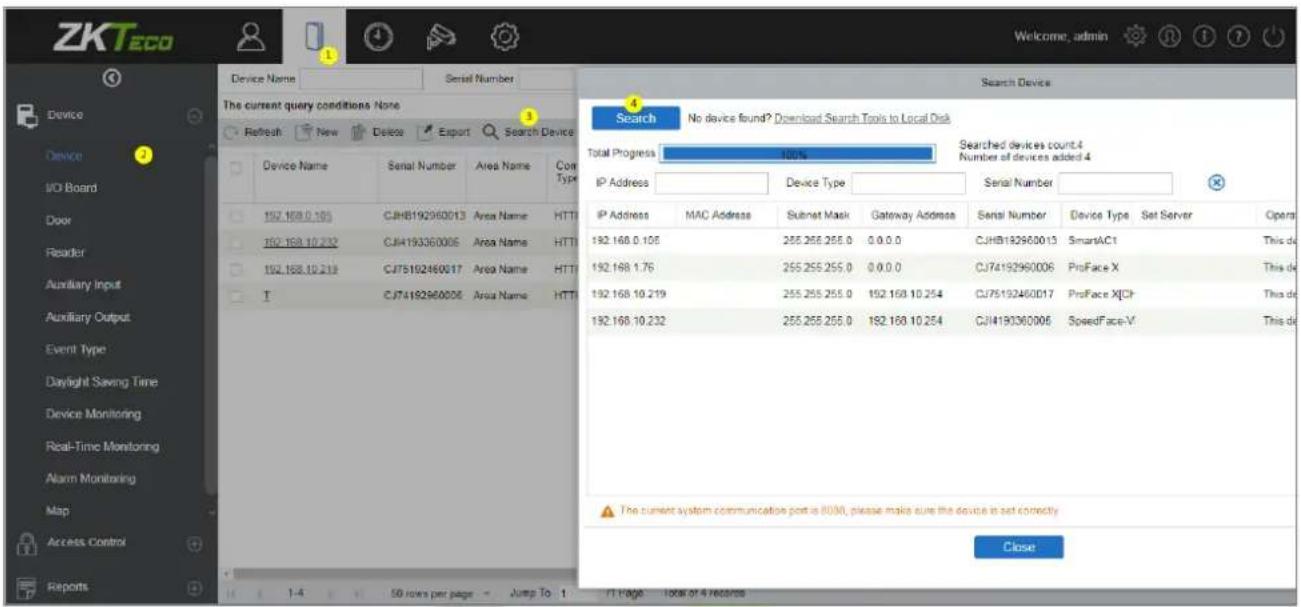
- Click Access > Device > Search Device to open the Search interface.
- Click Search, and it will prompt Searching......
- After the search is complete, the list and the total number of access controllers will be displayed.
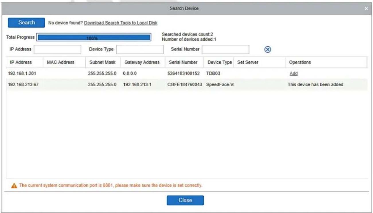

Note: UDP broadcast mode will be used to search the access devices. This mode cannot perform a s-router function. The IP address can provide a cross-net segment, but it must be in the same subnet, the Gateway and IP Address must be configured in the same network segment.
1. Click Add in the search list.
If the device is a pull device, you may enter a device name and click OK to complete adding the device.
![New Device Name* Communication Type* TCP/IP IP Address* Communication port* 4370 Communication Password Icon Type* Door Control Panel Type One-Door Access Cont Area* Area Name Add to Level ———— Clear Data in the Device when Adding [Clear Data in the Device when Adding] will delete data in the device (except event record), please use with caution! Save and New OK Cancel](/content/2026/05/1041552/images/58255fc277537425863513aae5a42a624c963e0e6597432bc193291e0729eb67.jpg)
Clear Data in the device when Adding: If this option is selected, after adding a device, the system will clear all data in the device (except the event logs).
If the device is a push firmware device, the following windows will pop-up after clicking Add. If the IP Address in New Server Address is selected, then configure the IP address and port number. If Domain Address in New Server Address option is selected, then set the Domain address, port number, and DNS. The device will be added to the software automatically.
![Add Device Name* 192.168.213.155 New Server Address* IP Address Domain Address 192 . 168 . 213 . 25 New Server Port* 8083 Communication Password Icon Type* Door Area* Area Name Add to Level Clear Data in the Device when Adding [Clear Data in the Device when Adding] will delete data in the device (except event record), please use with caution! OK Cancel](/content/2026/05/1041552/images/16137347db0a494ad9a79208e6460ceb340120b29da702693e2e8e2eeb6ed5f6.jpg)
![New Device Name* Communication Type* TCP/IP IP Address* Communication port* 4370 Communication Password Icon Type* Door Control Panel Type One-Door Access Cont Area* Area Name Add to Level Clear Data in the Device when Adding [Clear Data in the Device when Adding] will delete data in the device (except event record), please use with caution! Save and New OK Cancel](/content/2026/05/1041552/images/2371028b948ca7f9dfadb0ed1c09f1717fdbff5e79cc7fde36bc1a29c3edb59c.jpg)
New Server Address: To add a device by IP Address or Domain Address, devices can be added to the software by entering the domain address.
New Server Port: Set the access point of the system.
DNS: Set a DNS address of the server.
Clear Data in the Device when Adding: If this option is selected, then after adding a device, the system will clear all data in the device (except the event logs). If you add the device merely for demonstration or testing, there is no need to select it.

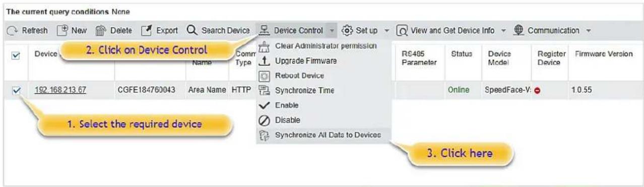
Note: When using either of the above three device adding methods, if there exists a residual data in the original device, please sync the original data to it after adding a new device to the software by clicking Device > Synchronize All Data to Devices, otherwise, these original data may conflict with normal usage.
- The default IP address of the access device may conflict with the IP of a device on the local network. You can modify its IP address: click Modify IP Address, and a dialog box will pop up in the interface. Enter the new IP address and other parameters (Note: Configure the gateway and IP address in the same network segment).

Note: Some PUSH devices support SSL. To use this function, select the HTTPS port during software installation and ensure that the device firmware supports SSL.
5.4.2 I/O Board
On the device module, click Device > I/O Board > New to add the I/O Board device to the software.
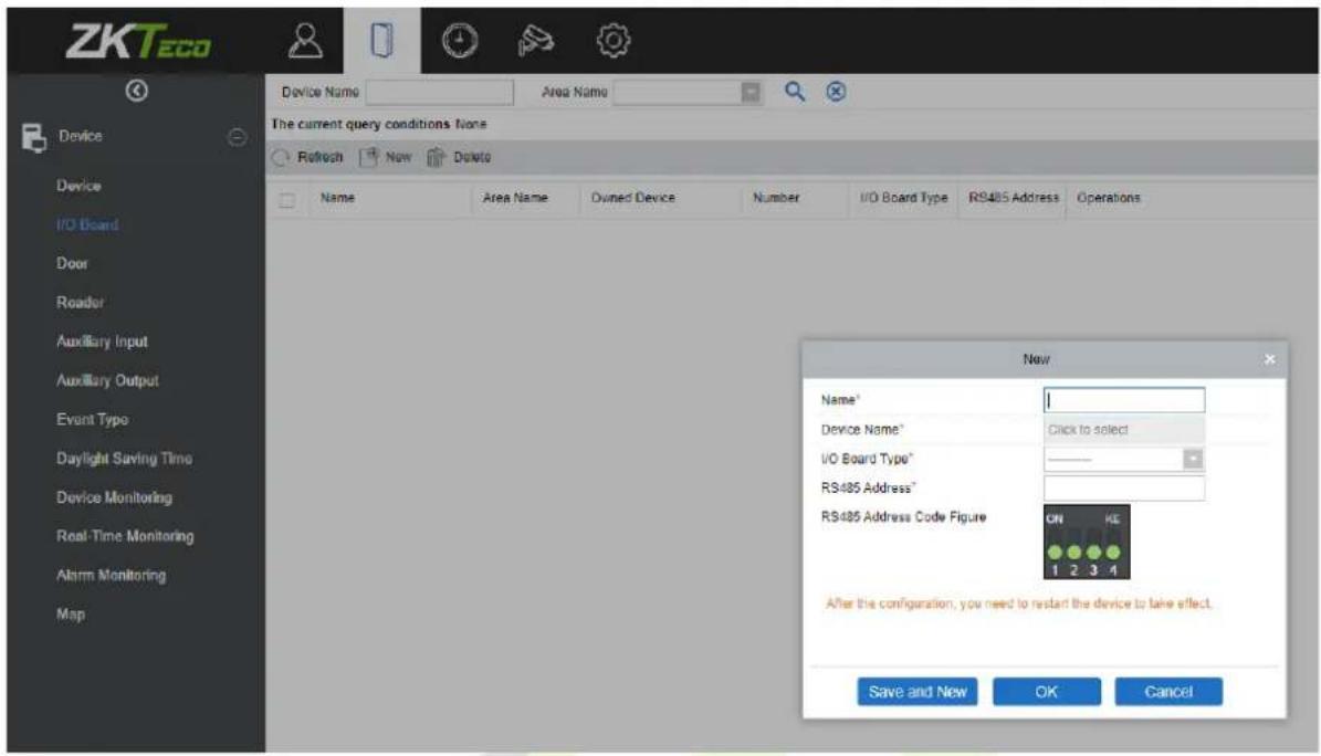
Enter the name of the I/O Board. Select the Device by clicking the Device Name field. The device list appears, as shown below:
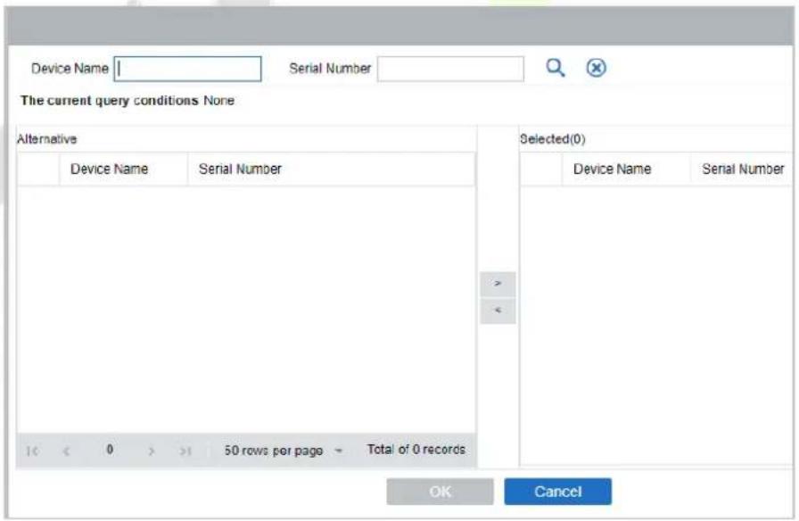
Select the device and click OK. Select the I/O Board Type. Set the RS485 Code Address by changing the corresponding button. Click OK to save the details. You can view all the auxiliary inputs in the Auxiliary Input interface.
Note: Please select this method when adding DM10 and AUX485.
5.4.3 Device Operation
For the communication between the system and device, data uploading, configuration downloading, device, and system parameters shall be set. Users can edit the access controllers within the appropriate levels in the current system; users can only add or delete devices in Device Management if needed.
| Refresh New Delete Export Search Device Device Control Set up View and Get Device Info Communication | ||||||||||||
| Device Name | Serial Number | Area Name | Communic Type | Network Connection Mode | IP Address | RS4 Para Get Devices Option Get Personnel Information Get Transactions | RS485 Parameter | Status | Device Model | Register Device | Firmware Version | Operations |
| SpeedFace-V5 | CGFE184760043 | Area Name | HTTP | Wired | 192.168.213.67 | View Rules of Devices View Device Capacity | ||||||
| SpeedFace-V5 | CGFE184760043 | Area Name | HTTP | Wired | 192.168.213.67 | View and Get Device Info | ||||||
• Edit or Delete a Device
Edit: Click the Device Name or click Edit to access the edit interface.
Delete: Select the device, click Delete, and click OK to delete the device.
![Edit Device Name* |SpeedFace-V5 Communication Type* TCP/IP HTTP Serial Number* CGFE184760043 IP Address* 192 . 168 . 213 . 67 Communication port* 6665 Icon Type* Door Control Panel Type One-Door Access Cont Area* Area Name Set Wiegand Reader Click to select the reader [Clear Data in the Device when Adding] will delete data in the device (except event record), please use with caution! OK Cancel](/content/2026/05/1041552/images/68f2620bddee2c6b494ca5aafd854e18a74bbe742495a2dd49e27f1bbfe6ce7c.jpg)
For further details and settings of the above parameters, see Device. Some details cannot be edited. The device Name should be unique and must not be identical to another device.
Control Panel Type cannot be modified. If the type is wrong, users need to delete the device and add it again manually.
- Export
Device information can be exported in EXCEL, PDF, and CSV file formats.
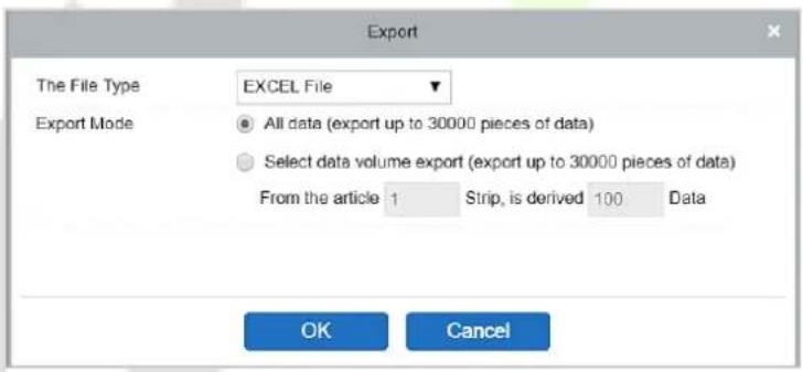
Device
| Device Name | Serial Number | Area Name | Communication Type | Network Connection Mode | IP Address | RS485 Parameter | Status | Device Model | Register Device | Firmware Version |
| SpeedFace-V5 | CGFE184760043 | Area Name | HTTP | Wired | 192.168.213.67 | Offline | SpeedFace-V5 | Yes | 1.0.55 |
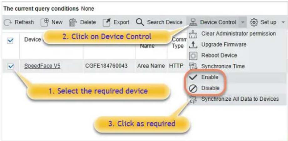
- Disable/Enable
Select a device, click Disable/ Enable to stop/ start using the device. When the communication between the device and the system is interrupted, or the device fails, the device may automatically appear in disabled status. After adjusting the local network or device, click Enable to reconnect the device and restore device communication.
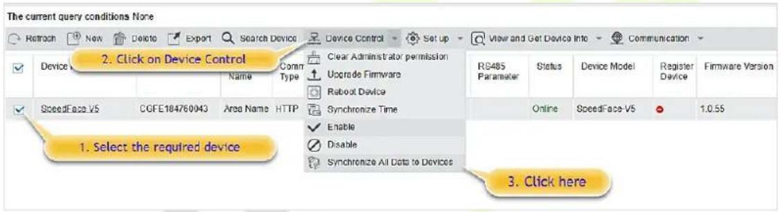
• Synchronize All Data to Devices
To synchronize data of the system to the device, select the device and click Synchronize All Data to Devices and click OK to complete synchronization.
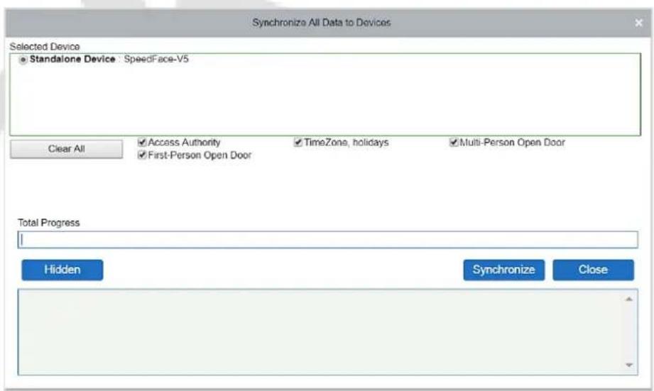
Note: Synchronize All Data to Devices will delete all the data in the device first (except transactions),
and thus download all settings again. Please keep the internet connection stable and avoid power down situations. If the device is working normally, please use this function with caution. Execute it in rare user situations to prevent impact on the regular use of the device.
• Upgrade Firmware
Select the required device that needs to be upgraded, click Upgrade firmware to enter the edit interface, then click Choose File to select the firmware upgrade file (named emfw.cfg) provided by the Access software, and click OK to start upgrading.
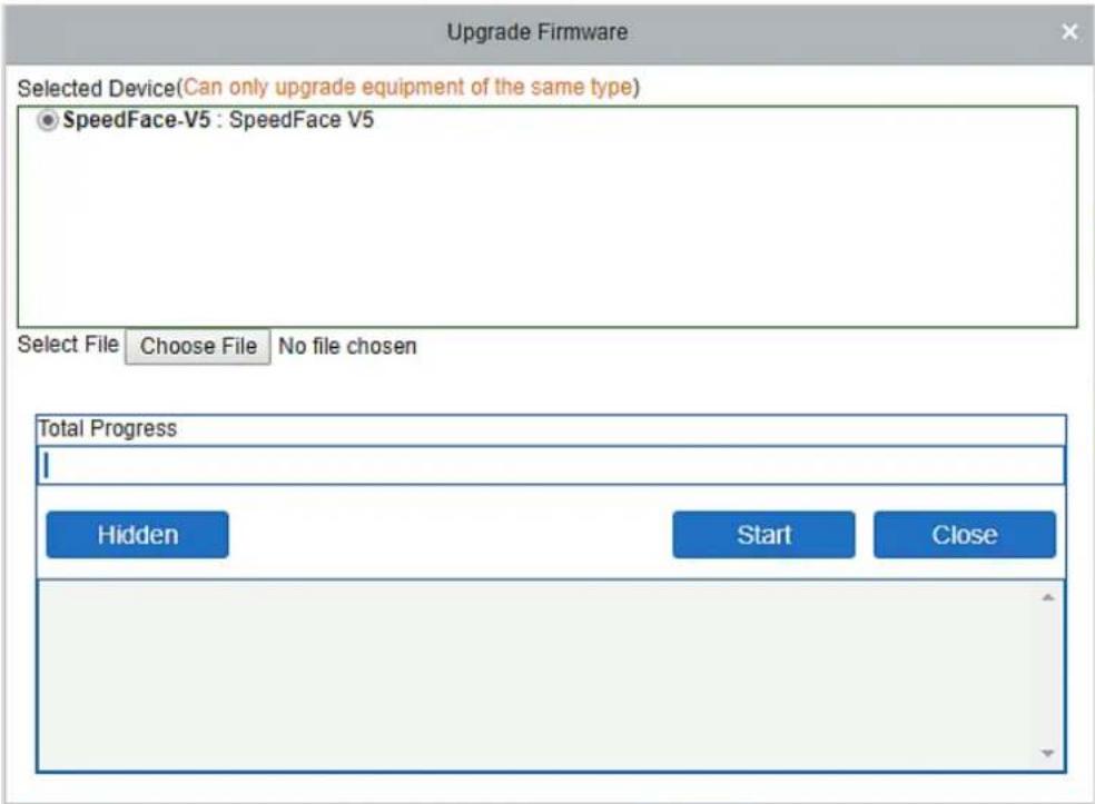

Note: The user shall not upgrade firmware without authorization. Contact the distributor before
upgrading the firmware or upgrade it by following the instructions of the distributor. The unauthorized upgrade may affect normal operations.
- Reboot Device
It will reboot the selected device.
- Synchronize Time
It will synchronize the device time with the server's current time.
- Set Device Time Zone
If the device supports the time zone settings and is not in the same time zone with the server, you need to set the time zone of the device. After setting the time zone, the device will automatically synchronize the time according to the time zone and server time.
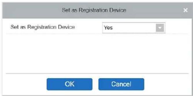
Set as Registration device
Set the registration device only when the standalone device's data such as personnel can automatically upload.
• Set Daylight Saving Time
According to the requirements of different regions, set the Daylight-Saving Time rules.
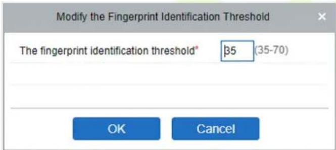
- Modify the fingerprint identification threshold (Ensure that the access controller supports fingerprint function)
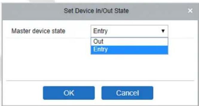
Set Device In/Out State
It will define the condition of the master device as Entry or Exit.
• Get Device Option
It gets the common parameters of the device. For example, it gets the firmware version after the device is updated.
• Get Personnel Information
It displays the current number of personnel, fingerprints, finger vein, and face templates in the device. The final value will be displayed in the device list.
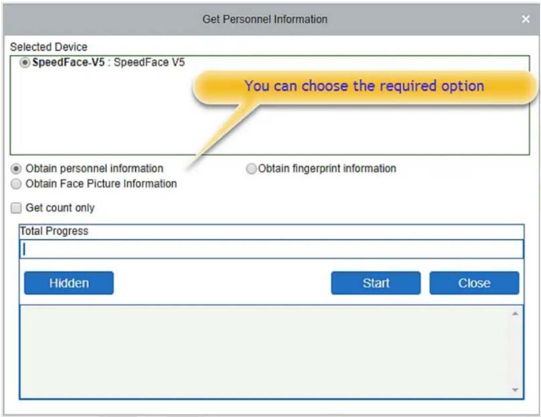
• Get Transactions
It fetches the transactions from the device into the system. Two options are provided for this operation: Get New Transactions and Get All Transactions.
Get New Transactions: The system only gets new transactions since the last collected and recorded transaction. Repeated transactions will not be rewritten.
Get All Transactions: The system will get transactions again. Repeated entries will not be shown twice.
When the network status is healthy, and the communication between the system and device is normal, the system will acquire the transactions of the device in real-time and save them into the system database. However, when the network is interrupted, or communication is interrupted for any reason, and the transactions of the device have not been uploaded into the system in real-time, Get Transactions can be used to acquire transactions of the device manually. Besides, the system, by default, will automatically acquire transactions of the device at 00:00 on each day.

Note: An Access controller can store up to 100 thousand transactions. When transactions exceed this
number, the device will automatically delete the oldest stored transactions (deletes 10 thousand transactions by default).
• View Rules of Devices
Shows the Access rules in the device.
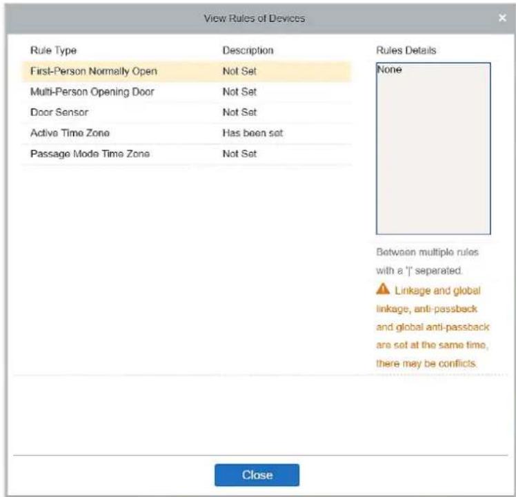
• View Device Capacity
It displays the capacity of personnel's biometric details in the device.
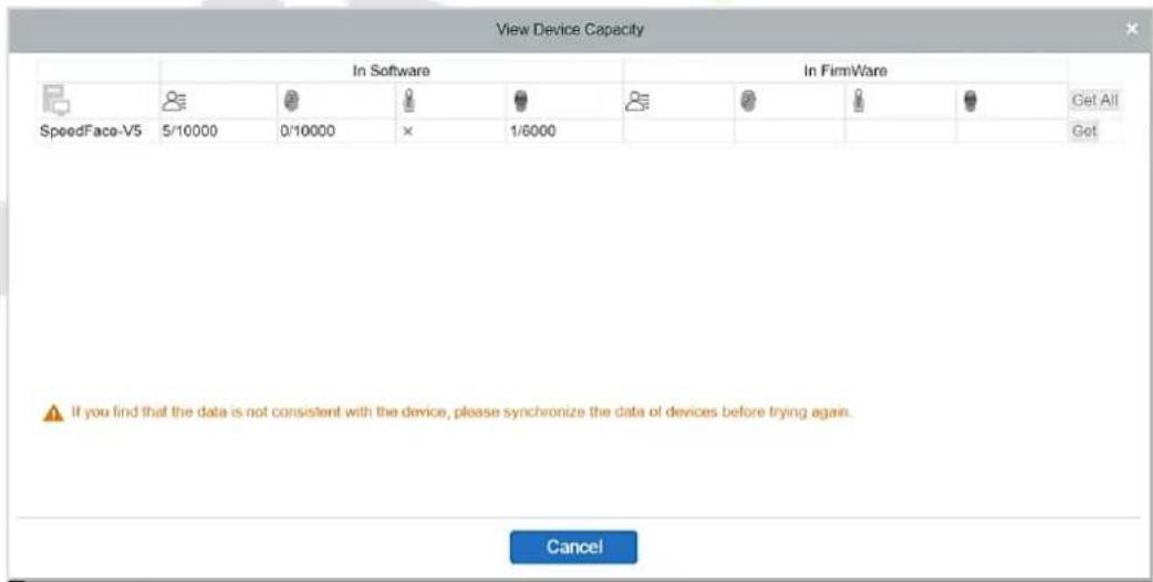
- Modify IP Address
Select a device and click [Modify IP address] to open the modification interface. It will obtain a real-time network gateway and subnet mask from the device. (Failed to do so, you cannot modify the IP address). Then enter a new IP address, gateway, and subnet mask. Click OK to save and quit. This function is similar to [Modify IP Address Function] in Device
Modify Communication Password
The system will ask for the old communication password before modifying it. After verification, enter the new password twice and click OK to alter the communication password.

Note: A Password should be a combination of numbers and letters of 6 digits.
Users can modify the fingerprint identification thresholds in the devices; it ranges from 35 to 70, and it is 55 by default. The system will read the thresholds from the device. Users can view the threshold devices list. More than one device can be changed by using the Batch operation function.
5.5 Add a user and a card
1. Click Personnel Management > Personnel > New.
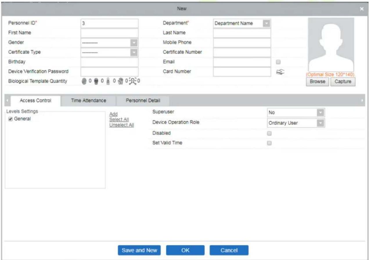
Fields are as follows:
Personnel ID: An ID may consist of up to 9 characters, within the range of 1 to 79999999. It can be configured based on your requirements. The Personnel ID contains only numbers by default but may also include letters.

Notes:
- When configuring a personnel number, check whether the current device supports the maximum length and whether letters can be used in Personnel ID.
- To edit the settings of the maximum number of characters of each personnel number and whether letters can also be used, click Personnel > Parameters.
Department: Select from the drop-down menu and click OK. If the department was not set previously, only one department named Company Name would appear.
First Name/Last Name: The maximum number of characters is 50.
Gender: Set the gender of personnel.
Mobile Phone: Enter the phone number of the user.
Certificate Type: There are four types of certificates: ID, Passport, Driver's License, and others.
Certificate Number: Enter the Certificate number.
Birthday: Enter the employee's Date of Birth.
Email: Enter the employee's Email ID. The max length is 30 characters.
Device Verification Password: Set the password for verifying with the device using personnel accounts. It can only contain up to 6-digits. It cannot be the same with other user's password and the duress password.
Card number: The max length is 10, and it should not be repeated.
Personal Photo: The picture preview function is provided, supporting common picture formats, such as JPG, JPEG, BMP, PNG, GIF, etc. The best size is 120×140 pixels.
Browse: Click Browse to select a photo on your local drive to upload.
Capture: Taking a photo by a camera is allowed when the server is connected with a camera.
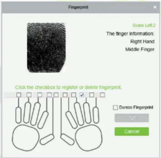
Register Fingerprint / Finger Vein: Enroll the Personnel Fingerprint, Finger Vein, Palm, or Face. To trigger the alarm and send the signal to the system, scan the Duress Fingerprint.
How to register fingerprint:

- Move the cursor to the fingerprint icon position, a registration pop-up or driver download dialog box will appear, click Register.
- Select a fingerprint, press the finger on the sensor continuously until the message "Fingerprint registered Successfully" is prompted.
- Click OK to complete the registration.
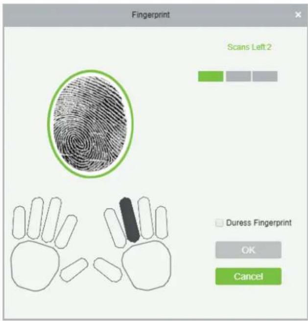
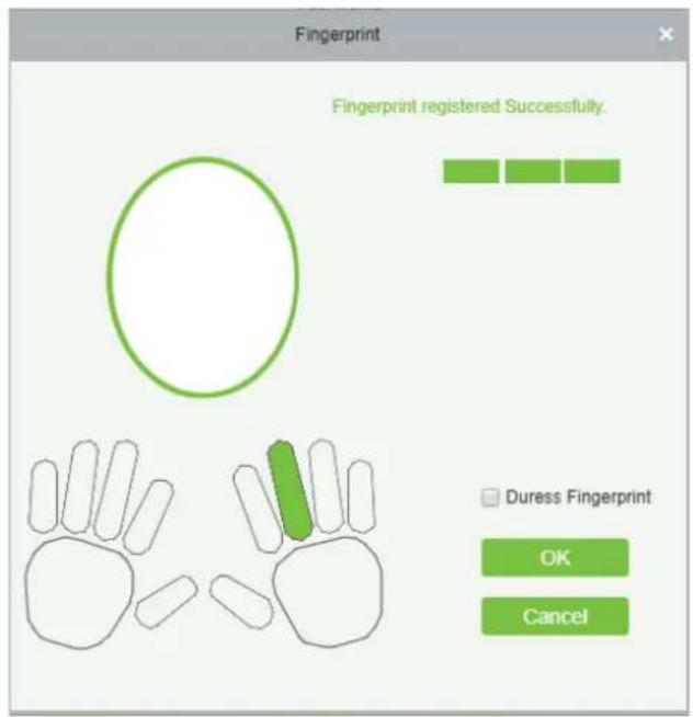
Click a fingerprint to delete. If you need to register a duress fingerprint, select the Duress Fingerprint checkbox.

Notes:
- If fingerprints are duplicated, "Don't repeat the fingerprint entry" will be prompted.
- If the fingerprint sensor driver is not installed, click "Install driver" and the system will prompt to download and install the driver.
- After installing the fingerprint sensor driver, if the fingerprint register button is grey in IE browser while it is normal in other browsers (such as Firefox, Google), you can change the settings of IE browser, as per the following:
a) In Internet Explorer, click Tools > Internet Options > Security > Credible Sites, add http://localhost to the credible sites, then restart the Internet Explorer.
b) In Internet Explorer, click Tools > Internet Options > Advanced > Reset to pop up a dialog of Reset Internet Explorer Settings, click Reset to confirm, then restart the Internet Explorer (you may try when Point 1 does not help).
c) If all the above settings do not work, please execute the following operations (take IE11 browser as an example): click Tools > Internet Options > Advanced > Security, check the option [Allow the software to run or install even if the signature is ...], and remove the selection of [Check for server certificate revocation], then restart IE.
d) If the browser version is below IE8, the fingerprint registration page will be different:
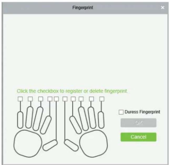
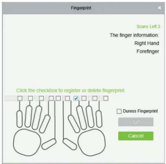
e) The system supports access from the Live20R fingerprint device and the fake fingerprint prevention function.
- To set the Access Control parameters for the personnel, click Access Control.
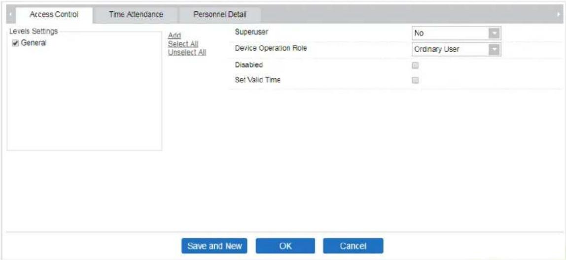
Fields are as follows:
Level Settings: Click Add, then set the passage rules of particular positions in different time zone.
![Add to Levels Level Name Time Zone The current query conditions None Alternative Selected(0) Level Name Time Zone >> > < << [<< 0 > ]] 50 rows per page OK Cancel](/content/2026/05/1041552/images/22294fa706bd0d798d99968fe0a6d30193280e77a991c009620b78ed00afd564.jpg)
Superuser: In the access controller operation, a superuser is not restricted by the regulations on time zones and has extremely high door-opening priority.
Device Operation Role: It will define the authority level in the device of the user.
Disabled: Temporarily disables the personnel's access level.
Set Valid Time: Doors can be set to open only within specific periods. If the checkbox is not selected, the door is always open.

Note: The system will automatically search for the relevant numbers in the departure library during verification.
The Personnel Information List, by default, is displayed as a table. If Graphic Display is selected, photos and numbers will be shown. Place the cursor on a photo to view the details about the personnel.

Notes:
- Not all devices support the "Disabled" function. When a user adds a device, the system will notify the user whether the current device supports this function or not. Please upgrade the device to use this function.
- Not all the devices support the "Set Valid Time" function. Some devices only allow the users to set the year, month, and day of the local time. When a user adds a device, the system will notify the user whether the current device supports this function or not. Please upgrade the device to use this function.
1. Click Personnel Detail to access the details and editing interface and enter the information.

2. After entering the information, click OK to save and exit, the personal details will be displayed in the added list.
5.6 Access Control Settings
The Access Control system can set the access levels of the registered users, namely, allowing some personnel to open some doors by verification during a period. Access Control System Management primarily includes Access Control Time Zones, Access Control Holiday, Door Settings, Access Levels, Personnel Access Levels, Real-Time Monitoring, and Reports, etc.
Access control system parameters
• 255 time zones.
• Unlimited access levels.
• Three-holiday types and 96 holidays in total.
• Anti-passback function.
• Multi-Card Opening function.
• Real-time monitoring.
• Interlock function.
- Linkage function.
• First-Card Normal Open function.
- Reader Settings.
• Auxiliary I/O Settings.
For more details, please refer to "ZKBioAccess User Manual."
5.7 Real-time monitoring
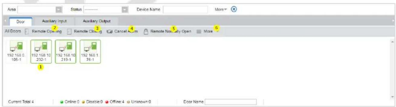
Click Access Device > Real-Time Monitoring.
It monitors the status and real-time events of doors configured to the access control panels in the system in real-time, including normal events and abnormal events (including alarm events).
The Real-Time Monitoring interface is shown as follows:
| Icons | Status | Icons | Status |
 | Device blocked | [S255] | Door Offline |
| [SKOW] | Door sensor not set; relay closed | [H4TH] | Door sensor not set; relay opened |
 | Door sensor not set, and the current firmware does not support the current action on the device | ||
| [XXTK] | Online status Door closed; Relay closed | Online status Door closed; Relay opened | |
| [8TSH] | Online status Door closed, and the current firmware does not support the current action on the device | ||
 | Online status Door opened; Relay closed | Online status Door opened; Relay opened | |
| [X02C] | Online status Door opened, and the current firmware does not support the current action on the device | ||
| [XX47] | Door opened alarm; Relay closed | [SK7S] | Door opened alarm; Relay opened |
 | Door opening timeout, Relay closed |  | Door opening timeout, Relay opened |
| [030D] | Door opening timeout and the current firmware does not support the current action on the device | ||
| [YBBV] | Door opening timeout, Relay closed/Door Sensor Closed | [HW2S] | Door opening timeout, Relay opened/Door Sensor Closed |
| [DSZ3] | Door closed alarm; Relay closed | [607A] | Door closed alarm; Relay opened |
| [YZSK] | Door closed alarm, indicates that the current fir [TTKH] does not support the current action on the device | ||
 | Door sensor not set, Door alarm, Relay closed |  | Door sensor unset, Door alarm, Relay opened |
 | Door opening timeout, without relay status/Door Sensor Closed |  | Door lock |
| Without relay status, it indicates that the current firmware does not support the action on the device. | |||
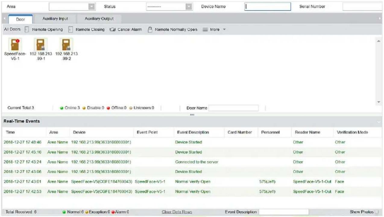
Different icons represent the status as follows:
1. Door
Remote Opening/Closing: It can control one door or all the doors.
To control a single door, right-click on it, and click Remote Opening/ Closing in the pop-up window. To manage all entries, directly click Remote Opening/ Closing in Current All option.
In the remote opening, the user can define the door opening duration (The default is 15s). You can select [Enable Intraday Passage Mode Time Zone] to enable the intraday door passage mode time zones or set the door to Normal Open, and then the door will not be limited to any time zones (can be opened at any time).
To close a door, select [Disable Intraday Passage Mode Time Zone] first, to avoid enabling other normal open time zones to open the door, and then select [Remote Closing].

Note: If [Remote Opening /Closing] fails, check whether the devices are disconnected or not. If
disconnected, check the network connectivity.
Cancel the alarm: Once an alarming door pops-up over the interface, the alarm sound will be played. Alarm cancellation can be made for a single door and all the entries. To control a single door, move the cursor over the door icon, a menu will pop-up, then click Remote Opening/ Closing on the menu. To manage all the doors, directly click Remote Opening/ Closing in Current All option.

Note: If Cancel the alarm fails, check if any devices are disconnected. If found disconnected, check
the network.
Remote Normally Open: It will set the device as normal open by remote.
• Quick Management of Doors
If you move the cursor over a door's icon, you can quickly perform the above-explained operations. Besides, you can query the latest events from the door.
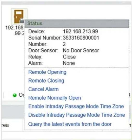
Query the latest events from the door: Click to view the current events on the door quickly.
Issue card to a person: If you swap an unregistered card, a record with a card number will pop-up in a real-time monitoring interface. Right-click that card number, and a menu will pop-out. Click "Issue card to person," to assign that card to one person.
• Multiple selections
You can select several doors at the same time to perform operations such as remote opening, remote closing, canceling alarm, etc. Double-click the door icon to edit the door properties.
• Event monitoring
The system will automatically acquire the records of devices being monitored (by default, it displays 200 records), including normal and abnormal access control events (including alarm events). Normal events
will appear in green; alarm events will appear in red; other abnormal events will appear in orange.
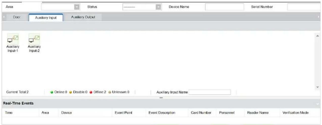
2. Auxiliary Input
It monitors the current auxiliary input events in real-time.
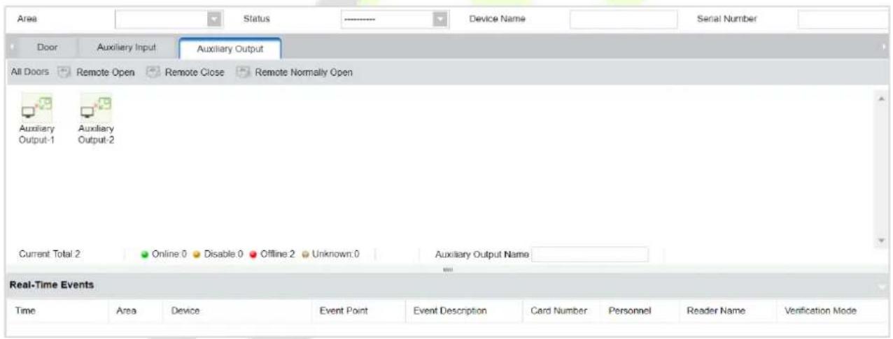
3. Auxiliary Output
Here you can perform Remote open, Remote Close, Remote Normally Open functions.
Reports 5.8
Since the data quantity of access control event control is large, you can view the specific access control events through query conditions. By default, the system displays the last three months' transactions. Click [Reports] > [All Transactions] to view all the transactions.
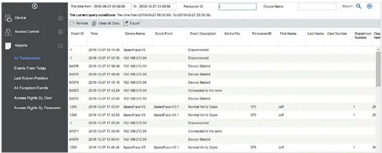
Media File: You can view or download the photos and videos.
Clear All Data: This function is used to clear all the transactions. Click [Clear All Data]. In the appearing pop-up, click OK to remove all the transactions.
Export: You can export all the transactions in Excel, PDF, and CSV format.
All Transactions
| Event ID | Time | Device Name | Event Point | Event Description | Personnel ID | First Name | Last Name | Card Number | Depart ment Number | Depart ment Name | Reader Name | Verification Mode | Area Name | Remark |
| -1 | 2018-12-27 19:15:48 | SpeedFace-V5 | Disconnected | Other | Other | Area Name | ||||||||
| -1 | 2018-12-27 17:57:30 | 192.168.213.99 | Disconnected | Other | Other | Area Name | ||||||||
| 64376 | 2018-12-27 17:56:04 | 192.168.213.99 | Device Started | Other | Other | Area Name | ||||||||
| 64375 | 2018-12-27 17:48:46 | 192.168.213.99 | Device Started | Other | Other | Area Name | ||||||||
| 64374 | 2018-12-27 17:45:16 | 192.168.213.99 | Device Started | Other | Other | Area Name | ||||||||
| 64373 | 2018-12-27 17:43:24 | 192.168.213.99 | Connected to the server | Other | Other | Area Name | ||||||||
| 64372 | 2018-12-27 17:43:06 | 192.168.213.99 | Device Started | Other | Other | Area Name | ||||||||
| 1255 | 2018-12-27 17:43:01 | SpeedFace-V5 | SpeedFace-V5-I | Normal Verify Open | 575 | Jeff | 1 | ZKTeco | SpeedFace-V5-1-Out | Face | Area Name | |||
| 1254 | 2018-12-27 17:42:53 | SpeedFace-V5 | SpeedFace-V5-I | Normal Verify Open | 575 | Jeff | 1 | ZKTeco | SpeedFace-V5-1-Out | Face | Area Name | |||
| -1 | 2018-12-27 17:25:29 | 192.168.213.99 | Disconnected | Other | Other | Area Name | ||||||||
| 64371 | 2018-12-27 13:56:46 | 192.168.213.99 | Connected to the server | Other | Other | Area Name | ||||||||
| 64370 | 2018-12-27 13:56:01 | 192.168.213.99 | Device Started | Other | Other | Area Name | ||||||||
| 1253 | 2018-12-27 11:46:48 | SpeedFace-V5 | SpeedFace-V5-I | Normal Verify Open | 575 | Jeff | 1 | ZKTeco | SpeedFace-V5-1-Out | Face | Area Name |
Appendix 1
Operating demonstration of connecting C2-260, WR485 and Wiegand reader
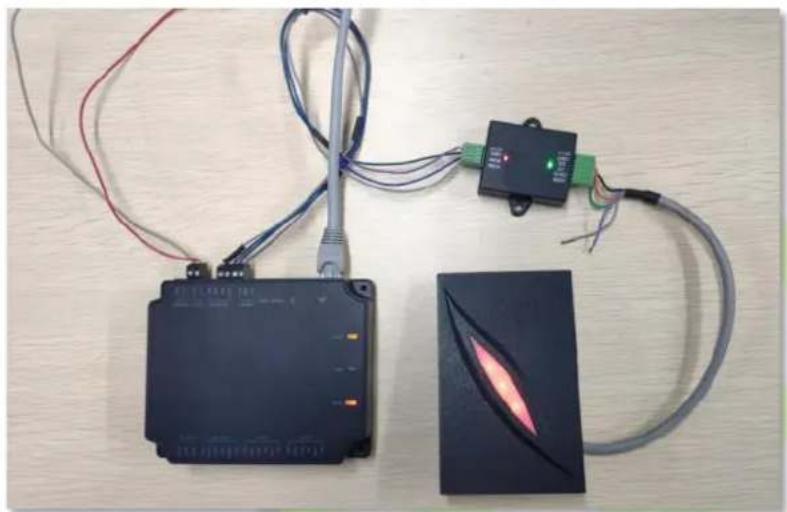
natural_image
Three electronic devices on a wooden surface: a black rectangular device with wires, a black rectangular device with a glowing orange light, and a dark rectangular device with coiled cable (no visible text or symbols)Step 1: Connect C2-260, WR485 and Wiegand reader according to the following circuit diagram.
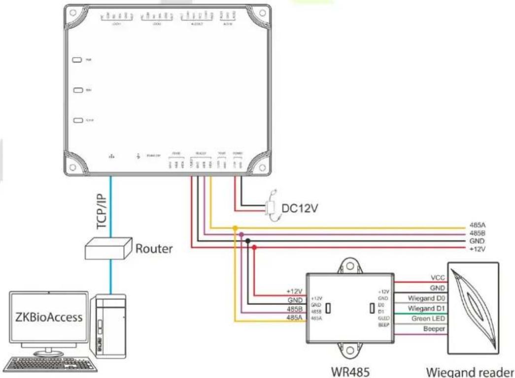
flowchart
graph TD
    A["ZKBioAccess"] -->|TCP/IP| B["Router"]
    B --> C["DC12V"]
    C --> D["WR485"]
    D --> E["Wiegand reader"]
    D --> F["VCC"]
    D --> G["GND"]
    D --> H["Wiegand D0"]
    D --> I["Wiegand D1"]
    D --> J["Green LED"]
    D --> K["Beeper"]
    D --> L["+12V"]
    D --> M["+12V GND"]
    D --> N["+12V GND 485A"]
    D --> O["+12V GND 485B"]
    D --> P["+12V GND 485A"]
    D --> Q["+12V GND 485B"]
    D --> R["+12V GND 485A"]
    D --> S["+12V GND 485B"]
    D --> T["+12V GND 485A"]
    D --> U["+12V GND 485B"]
    D --> V["+12V GND 485A"]
Step 2: Power on the C2-260 and connect to the network.
Step 3: Try to ping the C2-260 to check whether the network is good.
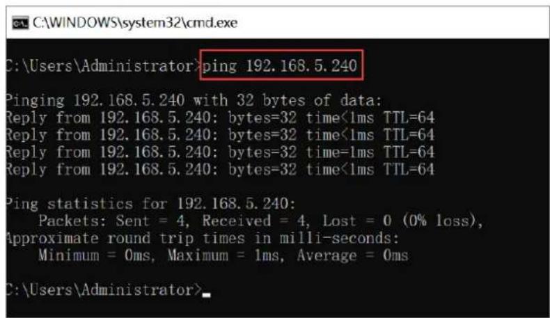
1) Press [Windows + R] of the computer at the same time to open the Run window and enter "cmd".
2) Enter "ping device IP address" to ping the C2-260 to check whether the communication is connected. As shown in the figure above.
Step 4: Adding the device on the ZKBioAccess IVS software.
1) Open the ZKBioAccess IVS software, and click Access > Device > Search to enter the Search interface. Click Search to search the device.
2) After the search is complete, the port number will be displayed on the bottom of the Search interface. From the following picture we can see server IP (192.168.5.111) and the port number (8088).
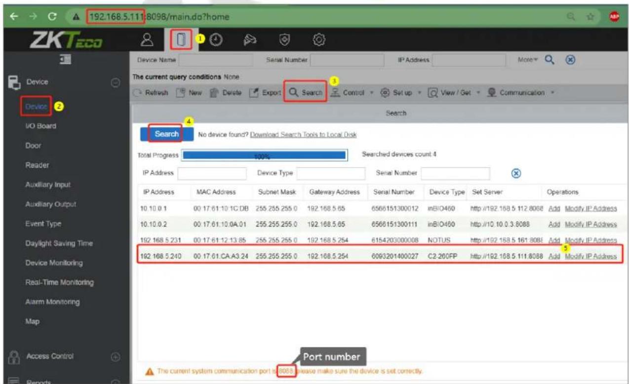
3) Click Add in the search list. Then input the server address (192.168.5.111), port (8088) and the other parameters on the pop-up window.
![Add Device Name* 192.168 5.240 New Server Address* IP Address ○Domain Address 192 168 5 111 New Server Port* 8088 Communication Password Icon Type* Door Area* 2 Add to Level 2 Clear Data in the Device when Adding ✓ [Clear Data in the Device when Adding] will delete data in the device (except event record), please use with caution! OK Cancel](/content/2026/05/1041552/images/de3644f03905d9d00981cc29402bbfc0d39a0017c581c26abf9bddfeefe91f91.jpg)
4) Click OK to save the setting. The following window will pop up if the device is successfully added.
![Add Device Name* 192.168.5.240 New Server Address* IP Address Domain Address Prompt The operation succeeded, the device will restart later. OK New Server Port* Communication Pas Icon Type* Area* Add to Level 2 Clear Data in the Device when Adding [Clear Data in the Device when Adding] will delete data in the device (except event record), please use with caution! OK Cancel](/content/2026/05/1041552/images/3d37b1ef63bd2661e208cb2fcd3c774c912e5089059077fdcfe91bea647cd3e5.jpg)
5) After completion, the device added to the software will be displayed in the device list.
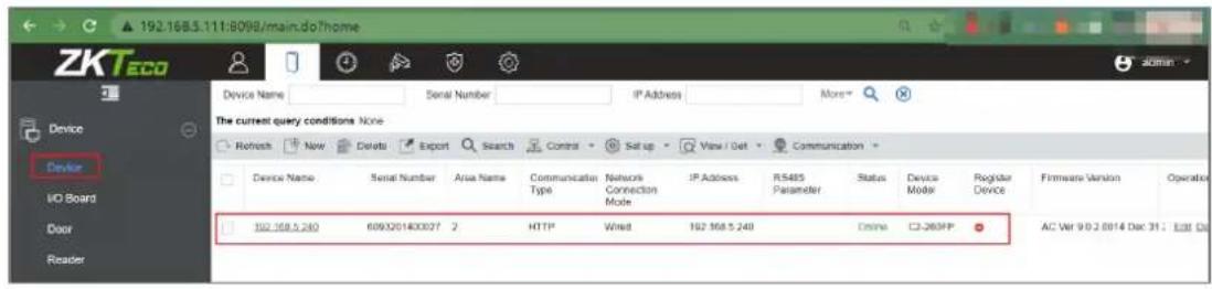
Step 5: Setting the wiegand reader parameters.
1) After adding the C2-260 to the software, click Access > Device > Reader to view the reader.
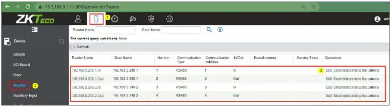
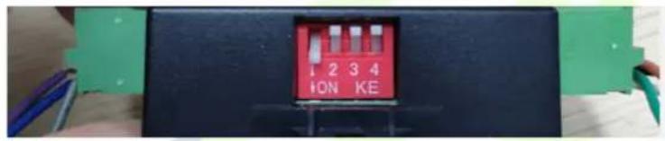
2) Set the WR485 address as 1. By setting the NO.1 of DIP switch to the ON position. It means that the wiegand reader which connect through WR485 be set as Door1(In) reader (Note: Recommended setting the WR485 addresses by the DIP switch before the power supply).
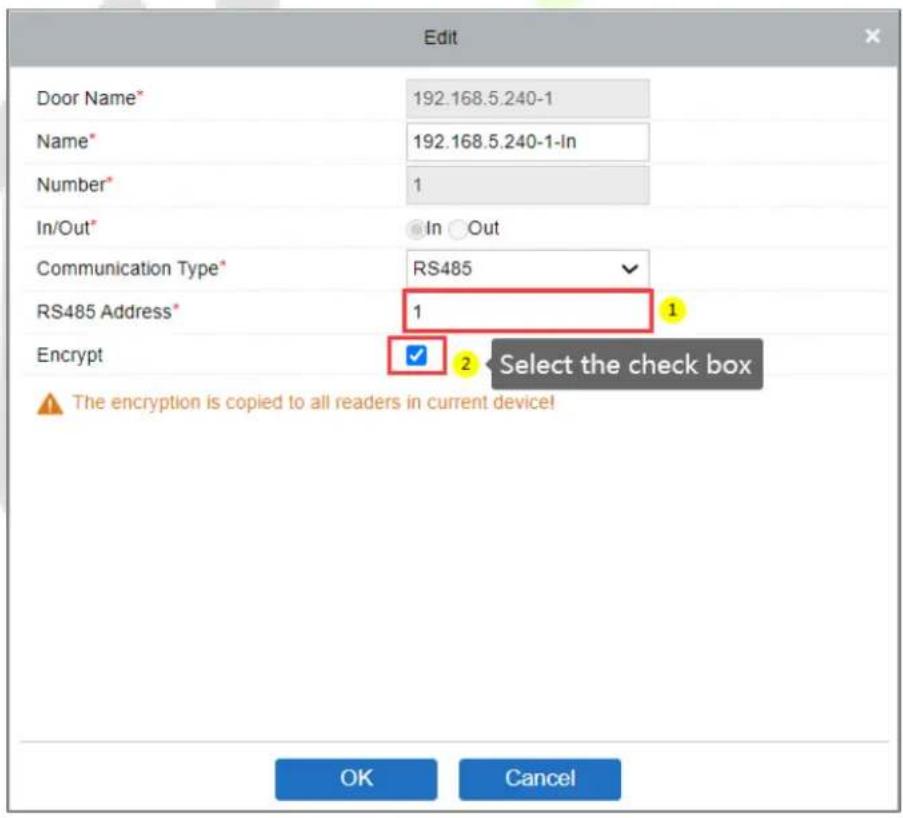
3) Click Edit of the "192.168.5.240-1-In" to set the parameters. Because the WR485 is an encryption mode, you need to select the encryption check box. So that the Wiegand reader can be used normally. As shown in the following figure.
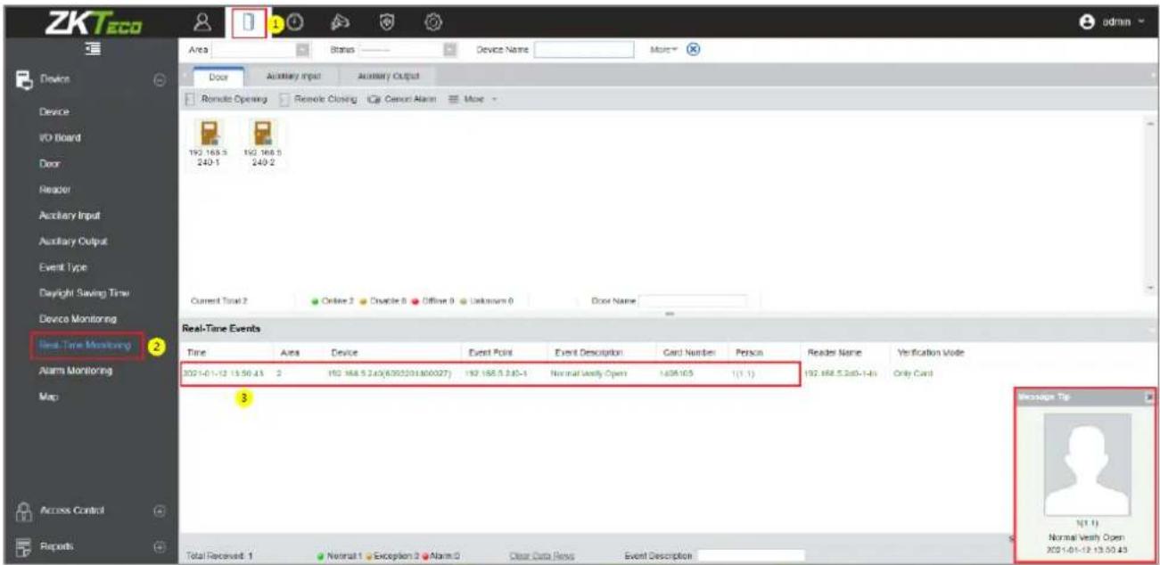
Step 6: View the real-time records.
After the setting is successful, when the employee swipes the card on the Wiegand reader, the real-time event can be viewed on the Real-TimeMonitoring page.
Click Access > Dvice > Real-TimeMonitoring to view the records.
Appendix 2
Statement on the Right to Privacy
Dear Customers,
Thank you for choosing this hybrid biometric recognition product, which was designed and manufactured by ZKTeco. As a world-renowned provider of core biometric recognition technologies, we are constantly developing and researching new products, and strive to follow the privacy laws of each country in which our products are sold.
We Declare That
- All our civilian fingerprint recognition devices capture only characteristics, not fingerprint images, and do not involve privacy protection.
- None of the fingerprint characteristics that we capture can be used to reconstruct an image of the original fingerprint and do not involve privacy protection.
- As the provider of this device, we will assume no direct or indirect responsibility for any consequences that may result from your use of this device.
- If you would like to dispute human rights or privacy issues concerning your use of our product, please directly contact your dealer.
Our other law-enforcement fingerprint devices or development tools can capture the original images of citizen's fingerprints. As to whether or not this constitutes an infringement of your rights, please contact your Government or the final supplier of the device. As the manufacturer of the device, we will assume no legal liability.
Note:
The Chinese law includes the following provisions on the personal freedom of its citizens:
- There shall be no illegal arrest, detention, search, or infringement of persons.
- Personal dignity is related to personal freedom and shall not be infringed upon.
- A citizen's house may not be infringed upon.
- A citizen's right to communication and the confidentiality of that communication is protected by the law.
As a final point, we would like to further emphasize that biometric recognition is an advanced technology that will be certainly used in E-commerce, banking, insurance, judicial, and other sectors in the future. Every year the world is subjected to major losses due to the insecure nature of passwords. The Biometric products serve to protect your identity in high-security environments.
Eco-friendly Operation

The product's "eco-friendly operational period" refers to the time period during which this product will not discharge any toxic or hazardous substances when used in accordance with the prerequisites in this manual.
The eco-friendly operational period specified for this product does not include batteries or other components that are easily worn down, and must be periodically replaced. The battery's eco-friendly operational period is 5 years.
Hazardous or Toxic substances and their quantities
| Component Name | Hazardous/Toxic Substance/Element | |||||
| Lead (Pb) | Mercury (Hg) | Cadmium (Cd) | Hexavalent chromium (Cr6+) | Polybrominated Biphenyls (PBB) | Polybrominated Diphenyl Ethers (PBDE) | |
| Chip Resistor | × | ○ | ○ | ○ | ○ | ○ |
| Chip Capacitor | × | ○ | ○ | ○ | ○ | ○ |
| Chip Inductor | × | ○ | ○ | ○ | ○ | ○ |
| Diode | × | ○ | ○ | ○ | ○ | ○ |
| ESD component | × | ○ | ○ | ○ | ○ | ○ |
| Buzzer | × | ○ | ○ | ○ | ○ | ○ |
| Adapter | × | ○ | ○ | ○ | ○ | ○ |
| Screws | ○ | ○ | ○ | × | ○ | ○ |
| ○ indicates that the total amount of toxic content in all the homogeneous materials is below the limit as specified in SJ/T 11363—2006.× indicates that the total amount of toxic content in all the homogeneous materials exceeds the limit as specified in SJ/T 11363—2006.Note:80% of this product's components are manufactured using non-toxic and eco-friendly materials. The components which contain toxins or harmful elements are included due to the current economic or technical limitations which prevent their replacement with non-toxic materials or elements. | ||||||
www.zkteco.eu
- C2-260 Access Control Panel
- Copyright © 2021 ZKTECO CO., LTD. All rights reserved.
- Trademark
- Disclaimer
- ZKTeco Europe
- About the Company
- About the Manual
- Document Conventions
- Table of Contents
- SAFETY INSTRUCTIONS......6
- SYSTEM INTRODUCTION....9
- INSTALLATION AND CONNECTION ....11
- EQUIPMENT COMMUNICATION 22
- ZKBIOACCESS....28
- APPENDIX 1....53 OPERATING DEMONSTRATION OF CONNECTING C2-260, WR485 AND WIEGAND READER....53
- APPENDIX 2....58
- Safety Instructions
- Important Security Instructions
- Installation Instructions
- System Introduction
- System Functional Parameters
- Product Technical Parameters
- Control Panel Indicators
- Installation and Connection
- Installation Procedure
- Installation of Access Control Panel Wires
- Remarks:
- Control Panel System Installation
- Schematic Diagram of System Installation
- Control Panel Connection Terminals
- • Description of the terminals:
- Connection with Door Sensors, Exit Switches, Auxiliary Input Devices, and RS485 Extension Communication
- Door sensor
- Exit switch
- Auxiliary input
- RS485 extension communication
- Note:
- Connection with RS485/Wiegand Readers
- • Connection with RS485 Readers
- • Connection with Wiegand Readers
- Notes:
- Relay Output Connection
- Equipment Communication
- Access Control Networking Wires and Wiring
- TCP/IP Communication
- ZKPanelWeb 4.3
- Log on to the Web Server
- - TCP/IP Settings
- • Communication Settings
- 1) Server Settings
- 2) Communication Password
- System
- 1) Time Settings
- 2) System Settings
- 3) Device Information
- ZKBioAccess
- Login 5.1
- Activate the System
- Modify Password 5.3
- Device 5.4
- Adding a Device
- Add Device by Searching Access Controllers.
- Click Add in the search list.
- I/O Board
- Device Operation
- • Edit or Delete a Device
- - Export
- - Disable/Enable
- • Synchronize All Data to Devices
- • Upgrade Firmware
- - Reboot Device
- - Synchronize Time
- - Set Device Time Zone
- Set as Registration device
- • Set Daylight Saving Time
- - Modify the fingerprint identification threshold (Ensure that the access controller supports fingerprint function)
- Set Device In/Out State
- • Get Device Option
- • Get Personnel Information
- • Get Transactions
- • View Rules of Devices
- • View Device Capacity
- - Modify IP Address
- Modify Communication Password
- Add a user and a card
- Click Personnel Management > Personnel > New.
- Fields are as follows:
- How to register fingerprint:
- Click Personnel Detail to access the details and editing interface and enter the information.
- After entering the information, click OK to save and exit, the personal details will be displayed in the added list.
- Access Control Settings
- Access control system parameters
- Real-time monitoring
- Door
- • Quick Management of Doors
- • Multiple selections
- • Event monitoring
- Auxiliary Input
- Auxiliary Output
- Reports 5.8
- Appendix 1
- Operating demonstration of connecting C2-260, WR485 and Wiegand reader
- Step 4: Adding the device on the ZKBioAccess IVS software.
- Step 5: Setting the wiegand reader parameters.
- Step 6: View the real-time records.
- Appendix 2
- Statement on the Right to Privacy
- Dear Customers,
- We Declare That
- Eco-friendly Operation
Brand : ZKTeco
Model : C2-260
Category : Access Control