
BDSG500 - Screwdriver BLACK & DECKER - Free user manual and instructions
Find the device manual for free BDSG500 BLACK & DECKER in PDF.


| Product Type | Cordless Screwdriver |
| Brand | Black & Decker |
| Model | BDSG500 |
| Rated Voltage | 12 V |
| Battery Type | Lithium-Ion |
| Battery Capacity | 1.5 Ah |
| Charging Time | Approximately 3 to 5 hours |
| Chuck Type | Hexagonal 1/4" (6.35 mm) |
| No-load Speed | 0 - 600 rpm |
| Max Torque | 10 Nm |
| Weight (with battery) | 1.2 kg |
| Dimensions (L x W x H) | 210 x 180 x 60 mm |
| Power Source | Rechargeable battery |
| Main Functions | Screwing and unscrewing |
| Maintenance and Cleaning | Clean with a dry cloth, avoid solvents |
| Safety | Wear safety glasses, do not expose to water |
| Spare Parts | Batteries, charger, bits available |
| Repairability | Repairable by an authorized center |
| Noise Level | 70 dB(A) |
| Vibrations | < 2.5 m/s² |
| Charger Type | Standard Black & Decker charger |
Frequently Asked Questions - BDSG500 BLACK & DECKER
User questions about BDSG500 BLACK & DECKER
0 question about this device. Answer the ones you know or ask your own.
Ask a new question about this device
Download the instructions for your Screwdriver in PDF format for free! Find your manual BDSG500 - BLACK & DECKER and take your electronic device back in hand. On this page are published all the documents necessary for the use of your device. BDSG500 by BLACK & DECKER.
USER MANUAL BDSG500 BLACK & DECKER
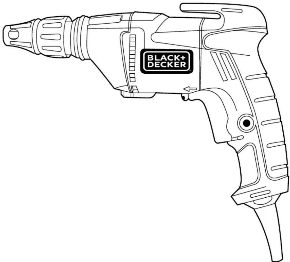
natural_image
Line drawing of a black and white electric drill with a 'BLACK+ DECKER' logo on the handle (no text or symbols beyond branding)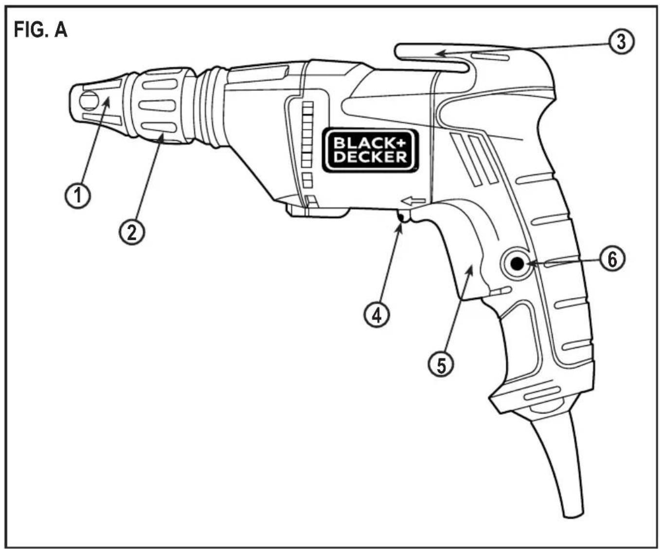
General Safety Rules
Warning! Read and understand all instructions. Failure to follow all instructions listed below, may result in electric shock, fire and/or serious personal injury.
Intended Use
This BLACK+DECKER screwdriver has been designed for driving drywall fasteners through drywall board into timber or metal framing studs.
Save These Instructions
General power tool safety warnings.

Warning! Read all safety warnings and all instructions. Failure to follow the warnings and instructions
listed below may result in electric shock, fire and/or serious injury.
Save all warnings and instructions for future reference. The term “power tool” in all of the warnings listed below refers to your mains operated (corded) power tool or battery operated (cordless) power tool.
1. Work Area Safety
a. Keep work area clean and well lit. Cluttered and dark areas invite accidents.
b. Do not operate power tools in explosive atmospheres, such as in the presence of fl ammable liquids, gases or dust. Power tools create sparks which may ignite the dust or fumes.
c. Keep children and bystanders away while operating a power tool.
Distractions can cause you to lose control.
2. Electrical Safety
a. Power tool plugs must match the outlet. Never modify the plug in any way. Do not use any adapter plugs with earthed (grounded) power tools. Unmodified plugs and matching outlets will reduce risk of electric shock.
b. Avoid body contact with earthed or grounded surfaces such as pipes, radiators, ranges and refrigerators.
There is an increased risk of electric shock if your body is earthed or grounded.
c. Do not expose power tools to rain or wet conditions. Water entering a power tool will increase the risk of electric shock.
d. Do not abuse the cord. Never use the cord for carrying, pulling or unplugging the power tool. Keep cord away from heat, oil, sharp edges or moving parts. Damaged or entangled cords increase the risk of electric shock.
e. When operating a power tool outdoors, use an extension cord suitable for outdoor use. Use of a cord suitable for outdoor use reduces the risk of electric shock.
f. If operating a power tool in a damp location is unavoidable, use a residual current device (RCD) protected supply. Use of an RCD reduces the risk of electric shock. Note: The term “Residual Curent Device (RCD)” can be replaced by “Ground Fault Circuit Interrupter (GFCI)” or by “Earth Leakage Circuit Breaker (ELCB)”.
3. Personal Safety
a. Stay alert, watch what you are doing and use common sense when operating a power tool. Do not use a power tool while you are tired or under the influence of drugs, alcohol or medication. A moment of inattention while operating power tools may result in serious personal injury.
b. Use personal protective equipment. Always wear eye protection. Protective equipment such as dust mask, non-skid safety shoes, hard hat, or hearing protection used for appropriate conditions will reduce personal injuries.
c. Prevent unintentional starting. Ensure the switch is in the off-position before connecting to power source and/or battery pack, picking up or carrying the tool. Carrying power tools with your finger on the switch or energising power tools that have the switch on invites accidents.
d. Remove any adjusting key or wrench before turning the power tool on. A wrench or a key left attached to a rotating part of the power tool may result in personal injury.
e. Do not overreach. Keep proper footing and balance at all times. This enables better control of the power tool in unexpected situations.
f. Dress properly. Do not wear loose clothing or jewellery. Keep your hair, clothing and gloves away from moving parts. Loose clothes, jewellery or long hair can be caught in moving parts.
g. If devices are provided for the connection of dust extraction and collection facilities, ensure these are connected and properly used. Use of these devices can reduce dust related hazards.
4. Power Tool Use and Care
a. Do not force the power tool. Use the correct power tool for your application. The correct power tool will do the job better and safer at the rate for which it was designed.
b. Do not use the power tool if the switch does not turn it on and off. Any power tool that cannot be controlled with the switch is dangerous and must be repaired.
c. Disconnect the plug from the power source and/or the battery pack from the power tool before making any adjustments, changing accessories, or storing power tools. Such preventive safety measures reduce the risk of starting the power tool accidentally.
d. Store idle power tools out of the reach of children and do not allow persons unfamiliar with the power tool or these instructions to operate the power tool.
Power tools are dangerous in the hands of untrained users.
e. Maintain power tools. Check for misalignment or binding of moving parts, breakage of parts and any other condition that may affect the power tools operation. If damaged, have the power tool repaired before use. Many accidents are caused by poorly
maintained power tools.
f. Keep cutting tools sharp and clean.
Properly maintained cutting tools with sharp cutting edges are less likely to bind and are easier to control.
g. Use the power tool, accessories and tool bits etc. in accordance with these instructions, taking into account the working conditions and the work to be performed. Use of the power tool for operations different from those intended could result in a hazardous situation.
5. Service
a. Have your power tool serviced by a qualified repair person using only identical replacement parts. This will ensure that the safety of the power tool is maintained.
6. Electrical safety

Your tool is double insulated; therefore no earth wire is required. Always check that the main voltage corresponds to the voltage on the rating plate.

Warning! If the power cord is damaged, it must be replaced by the manufacturer, authorized
BLACK+DECKER Service Center or an equally qualified person in order to avoid damage or injury. If the power cord is replaced by an equally qualified person, but not authorized by BLACK+DECKER, the warranty will not be valid.
- Labels on tool
The label on your tool may include the following symbols:
| Read Instructions Manual | Hz...... Hertz W...... Watts | Class II Construction |
| Use Eye Protection | min...... minutes | Earthing Terminal |
| Use Ear Protection | ~...... Alternating Current | Safety Alert Symbol |
| V...... Volts | Direct Current | ../min.. Revolutions or Recipro- cation per minute |
| A...... Amperes n | 0...... No-Load Speed |
Features (Fig. A)
- Depth stop
- Depth adjuster
- Belt clip
- Forward/Reverse switch
- Variable speed trigger switch
- Lock-on button
Specific Safety Rules
Hold power tool by insulated gripping surfaces, when performing an operation where the fastener may contact hidden wiring or its own cord. Fasteners contacting a "live" wire may make exposed metal parts of the power tool "live" and could give the operator an electric shock.
Warning! Know your drywall screwdriver. Do not plug the tool into the power source until you have read and understand this Instruction Manual. Learn the tool's applications and limitations, as well as the specific potential hazards related to this tool.
- Following this rule will reduce the risk of electric shock, fi re, or serious injury.
- Always wear eye protection. Any power tool can throw foreign objects into your eyes and cause permanent eye damage. ALWAYS wear safety goggles (not glasses) that comply with ANSI safety standard Z87.1. Everyday glasses have only impact resistant lenses. They ARE NOT safety glasses
Warning! Glasses or goggles not in compliance with ANSI Z87.1 could cause serious injury when they break.
- Never use the drywall screwdriver to drive screws other than drywall screws. The drywall screwdriver and the screwdriver bits are designed specifically for driving drywall screws.
- Only use screwdriver bits that are designed for use with this tool.
- Always keep hands out of the path of the drywall screw.
- Make sure there are no nails or foreign objects in the part of the workpiece to be cut or sanded.
- To avoid injury from accidental starting, always remove the plug from the power source before installing or removing a screwdriver bit or when adjusting the depth control.
- Always check the wall area where screws will be driven to be sure there are no hidden electrical wires in the area.
- Never leave the Lock-on button ON. Before plugging the tool into the power source, make sure the lock-on button is OFF.
General Safety Warnings
Warning! Wear a dust mask that is designed to be used when operating a power tool in a dusty environment.
Warning! Dust that is created by power sanding, sawing, grinding, drilling, and other construction activities may contain chemicals that are known to cause cancer, birth defects, or other genetic abnormalities. These chemicals include:
- Lead from lead-based paints
- Crystalline silica from bricks, cement, and other masonry products
- Arsenic and chromium from chemically treate lumber
The level of risk from exposure to these chemicals varies, according to how often this type of work is performed. In order to reduce exposure to these chemicals, work in a well-ventilated area, and use approved safety equipment, such as a dust mask that is specifically designed to filter out microscopic particles.
Residual risks
Additional residual risks may arise when using the tool which may not be included in the enclosed safety warnings. These risks can arise from misuse, prolonged use etc. Even with the application of the relevant safety regulations and the implementation of safety devices, certain residual risks can not be avoided. These include:
- Injuries caused by touching any rotating/moving parts.
- Injuries caused when changing any parts, blades or ac cessories.
- Injuries caused by prolonged use of a tool. When using any tool for prolonged periods ensure you take regular breaks.
- Impairment of hearing.
- Health hazards caused by breathing dust developed when using your tool (example:- working with wood, especially oak, beech and MDF.)
Vibration
The declared vibration emission values stated in the technical data and the declaration of conformity have been measured in accordance with a standard test method provided by EN 60745 and may be used for comparing one tool with another. The declared vibration emission value may also be used in a preliminary assessment of exposure.
Warning! The vibration emission value during actual use of the power tool can differ from the declared value depending on the ways in which the tool is used. The vibration level may increase above the level stated.
When assessing vibration exposure to determine safety measures required by 2002/44/EC to protect persons regularly using power tools in employment, an estimation of vibration exposure should consider, the actual conditions of use and the way the tool is used, including taking account of all parts of the operating cycle such as the times when the tool is switched off and when it is running idle in addition to the trigger time.
Extension Cord Safety
Warning! Keep the extension cord clear of the working area. Position the cord so it will not get caught on the workpiece, tools or any other obstructions while you are working with the power tool.
Make sure any extension cord used with this tool is in good condition. When using an extension cord, be sure to use one of heavy enough gauge to carry the current the tool will draw. An undersized cord will cause a drop in line voltage resulting in loss of power and overheating.
Be sure your extension cord is properly wired and in good condition. Always replace a damaged extension cord or have it repaired by a qualified electrician before using it. Protect your extension cord from sharp objects, excessive heat and damp or wet areas.
Use a separate electrical circuit for your power tools. This circuit must not be less than 14 gauge wire and should be protected with either a 15 A time delayed fuse or circuit breaker. Before connecting the power tool to the power source, make sure the switch is in the OFF position and the power source is the same as indicated on the nameplate. Running at lower voltage will damage the motor.
Contents
Carefully unpack the drywall screwdriver. Compare the contents against the “Drywall screwdriver components” chart below.
Assembly and Operating
Warning! To avoid fire or toxic reaction, never use gasoline, naphtha, acetone, lacquer thinner or similar highly volatile solvents to clean the tool.
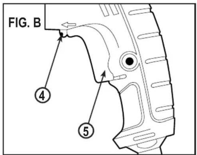
Forward/Reverse switch (Fig. B)
The forward/reverse switch (4) is conveniently mounted in front of the variable speed trigger switch (5). To make the screwdriver rotate clockwise for driving screws, push the forward/ reverse switch (4) to the left. To make the screwdriver rotate counter-clockwise to remove screws, push the forward/reverse switch (4) to the right.
Notes:
a. Never change the position of the forward/ reverse switch (4) while the screwdriver bit is turning.
b. The variable speed trigger switch (5) will NOT function with the forward/reverse switch (4) in the middle position.
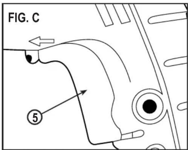
Variable speed trigger switch (Fig. C)
This screwdriver is equipped with a variable speed On/Off trigger switch.
-
To start screwdriver, gently squeeze the variable speed trigger switch (5). Note: The screwdriver will turn at its slowest speed when the variable speed trigger switch is depressed slightly. The screwdriver will turn at its fastest speed when the variable speed trigger switch is fully depressed.
-
To stop the screwdriver, release the variable speed trigger switch (5).
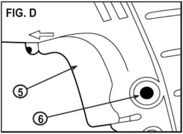
Lock-on button (Fig. D)
The lock-on button feature allows the trigger switch to be locked in the ON position at full speed when continuous operation for extended periods of time is required.
To lock the lock-on button in the ON position, pull back on the variable speed trigger switch (5) to start the screwdriver and push the lock-on button (6) into the screwdriver handle. Release the variable speed trigger switch while holding the lock-on button into the screwdriver handle. The screwdriver will continue to run. To release the lock-on button, pull variable speed trigger switch back (5) and then release the trigger.
Note: Operating the screwdriver with the variable speed trigger switch for an extended period of time may cause the screwdriver motor to overheat. If the screwdriver gets hot, stop driving screws and allow it to cool for at least 15 minutes.
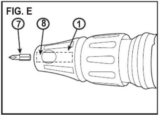
Inserting a screwdriver bit (Fig. E)
This tool has a magnetic bit holder that provides convenient bit changes. To install a bit, simply insert the hex bit shank (7) into the magnetic bit holder (8) that is located inside the depth stop (1). Push the bit into the magnetic bit holder until the magnet holds the bit in place.
Notes:
a. Use only 1" (25 mm) long bits that are designed for use in driving drywall screws.
b. Make sure the bit size is correct for the drywall screws being driven. This will usually be a #2 size.
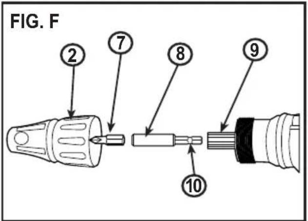
Replacing the magnetic bit holder (Fig. F)
If the magnetic bit holder becomes worn or damaged, it must be replaced. The replacement bit holder must be of the same dimensions as the original and have the ANSI retention groove on the end that is inserted into the tool.
- Remove the nosepiece (2) by turning it counter clockwise.
Note: Do not use pliers on the nosepiece.
Only use your hand. - Grasp the screwdriver bit (7) with pliers and pull it out of the magnetic bit holder (8).
- Grasp the large end of the bit holder with pliers and pull it straight out of the screwdriver spindle (9).
- Reverse the process by inserting the replacement magnetic bit holder into the tool.
Note: When inserting the replacement for magnetic bit holder, gently tap it into place to make sure it is fully inserted. Grasp the large end of the magnetic bit holder to ensure the retention groove (10) is holding the magnetic bit holder in place in the tool. - Reinstall the screwdriver bit and nose piece.
Safety Recommendations
Check the following every time you use the screwdriver:
- Wear safety glasses or a mask.
- Use hearing protection.
- The screwdriver tip is the right size and it is in good condition.
- No power cables "live" where you are inserting the screws.
Note: Failure to follow these safety rules will significantly increase the risk of injury.
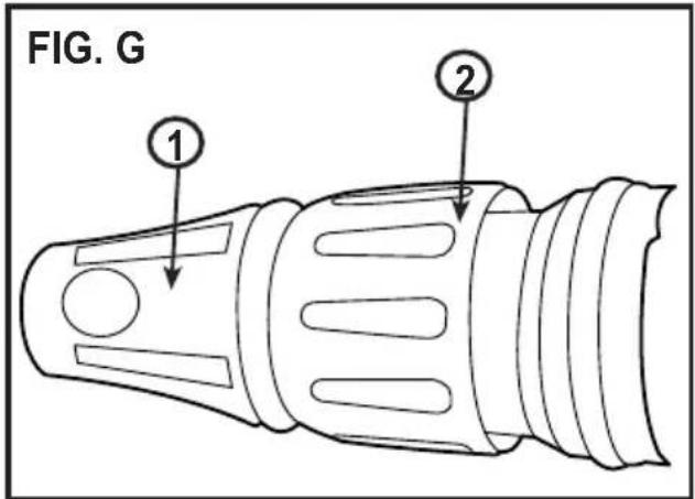
Adjusting the screwdrive bit depth (Fig. G)
It is important to control the depth to which the drywall screw will be driven. Over driving the screw will drive the screw too deep and break the outer paper layer of the drywall. Under driving the screw will leave the screw head above the drywall surface making it impossible to properly finish the drywall.
The depth control system is made up of the depth stop (1) and the depth adjuster (2).
Warning! The following adjustments should always be verified using a scrap piece of drywall to avoid damaging the “good” drywall sections.
-
Rotate the depth adjuster counter clockwise until approximately 1/4" of the screwdriver bit extends beyond the depth stop.
-
Place a drywall screw onto the screwdriver bit. The magnetized bit will hold the screw onto the bit.
Note: Before driving the screw, press the screw point into the drywall and make sure the screw is perpendicular to the drywall.
-
Press the screw against the drywall with steady even pressure and squeeze the trigger switch. The clutch in the tool will engage and the screw will be driven to the preset depth.
-
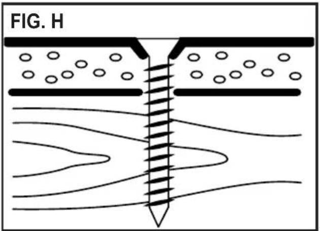
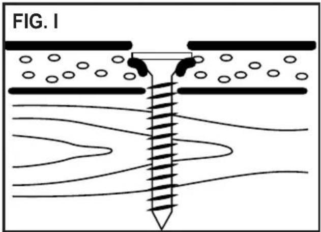
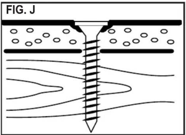
If the screw is not driven deep enough, the head of the screw will not be recessed into the drywall (Fig. H). In this case, turn the depth adjustment sleeve clockwise until the correct depth has been achieved. If the screw is driven too deep, it will be recessed too far into the drywall and the outer paper of the drywall will be fractured (Fig. I). In this case, turn the depth adjustment sleeve counter clockwise until the correct depth has been achieved. Fig. J illustrates the correct depth for the screw to be driven.
Note: For each revolution the depth adjustment sleeve is rotated, the depth will increase/decrease approximately 1/16" (1.6 mm).
Tips for driving drywall screws
- Always drive the screws perpendicular to the drywall so the heads are properly countersunk. They should never be driven at an angle.
- Support the tool with both hands wherever possible. This will provide better control over the tool help eliminate screws being driven at an angle.
- Place the drywall screw on the screwdriver bit. The magnetic bit holder will hold any steel screw for easy starting.
- Press the screw against the drywall with steady even pressure and squeeze the variable speed trigger switch. The clutch in the tool will engage and the screw will be driven to the preset depth. Once fully driven, the clutch will make a chattering sound until the variable speed trigger is released.
- When the screw is properly driven, the screw head will be slightly countersunk into the drywall without breaking the outer drywall paper. At this point, the clutch will release to prevent over driving the screw. This will result in minimum work to fill the holes and taping the seams.
- The belt clip allows you to conveniently attached the screwdriver to your belt. This will allow you to use both hands for positioning the drywall.
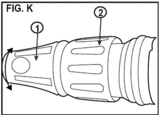
Removing drywall screws (Fig. K)
To remove drywall screws, remove the depth stop (1) to expose the screwdriver bit.
Notes:
a. The depth stop is a press fi t onto the depth adjuster (2). Simply twist and pull outward to slide it off the depth adjuster.
b. You can also turn the depth adjuster clockwise to expose the screwdriver bit. This however will cause you to lose the depth setting and you will have to re-set the depth.
Maintenance
Keep guards, air vents and the motor housing as clear as possible of dust and dirt. Wipe with a clean cloth and blow through with a low-pressure air supply. Excessive build-up of metal dust can cause tracking of electrical current from the internal parts to exposed metal parts.
Warning! When servicing, use only identical replacement parts. The use of any other part may create a hazard or cause product damage.
- DO NOT use solvents when cleaning plastic parts. Plastics are susceptible to damage from various types of commercial solvents and may be damaged by their use. Use a clean cloth to remove dirt, dust, oil, grease etc.
Warning! Do not allow brake fluids, gasoline, petroleum-based products, penetrating oils, etc. to come into contact with plastic parts. They contain chemicals that can damage, weaken or destroy plastic.
- Remove accumulated dust and debris regularly using a SOFT and DRY brush.
Warning! Use safety goggles when using an air jet to blow dust out of the tool. Keep air vents clean and unobstructed to allow maximum airflow through the tool.
- DO NOT abuse power tools. Abusive practices can damage the tool and the workpiece.
Warning! DO NOT attempt to modify tools or create accessories. Any such alteration or modification is misuse and could result in a hazardous condition leading to possible serious injury. It will also void the warranty.
Lubrication
All of the bearings in this tool are lubricated with a sufficient amount of high-grade lubricant for the life of the unit under normal conditions. Therefore, no further lubrication is required.
Cleaning
Use only mild soap and a slightly damp cloth to clean your angle grinder. Many
household cleaners contain chemicals which could seriously damage the plastic. Also, do not use petrol, turpentine, lacquer or paint thinners or similar products. Never let any liquid get inside the tool and never immerse any part of the tool into liquid.
Important! To assure product SAFETY and RELIABILITY, repairs, maintenance and adjustment (other than those listed in this manual) should be performed by authorized service centers or other qualified service personnel, always using identical replacement parts.
Specifications
BDSG500
Power 520W
Voltage
TR voltage 230V \~ 50Hz
No-load speed 0 - 4500/min (rpm)
Weight 3.3lb (1,45kg)
Level of sound pressure according to EN 60745:
Sound pressure ( L_pA ) 82 dB(A), uncertainty (K) 3 dB(A)
Sound power ( L_WA ) 93 dB(A), uncertainty (K) 3 dB(A)
Vibration total values (triax vector sum) according to EN 60745:
Screwdriving without impact ( a_h,s ) 3,5 m/s ^2 , uncertainty (K) 1.5 m/s ^2
EC declaration of conformity
MACHINERY DIRECTIVE

BDSG500
BLACK+DECKER declares that these products described under "technical data" are in compliance with: 2006/42/EC, EN 60745-1, EN 60745-2-2.
These products also comply with Directive 2014/30/EU and 2011/65/EU. For more information, please contact BLACK+DECKER at the following address or refer to the back of the manual.
The undersigned is responsible for compilation of the technical file and makes this declaration on behalf of BLACK+DECKER.
R.Laverick
Engineering Manager BLACK+DECKER Europe, 210 Bath Road, Slough, Berkshire, SL1 3YD United Kingdom 11.2015
Protecting the environment
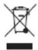
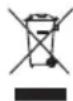
Separate collection. This product must not be disposed of with normal household waste.
Should you find one day that your BLACK+DECKER product needs replacement, or if it is of no further use to you, do not dispose of it with household waste. Make this product available for separate collection.

Separate collection of used products and packaging allows materials to be recycled and used again. Reuse of recycled materials helps prevent environmental pollution and reduces the demand for raw materials.
Local regulations may provide for separate collection of electrical products from the household, at municipal waste sites or by the retailer when you purchase a new product.
BLACK+DECKER provides a facility for the collection and recycling of BLACK+DECKER products once they have reached the end of their working life. To take advantage of this service please return your product to any authorised repair agent who will collect them on our behalf.
You can check the location of your nearest authorised repair agent by contacting your local BLACK+DECKER office at the address indicated in this manual. Alternatively, a list of authorised BLACK+DECKER repair agents and full details of our after-sales service and contacts are available on the Internet at: www.2helpU.com.
Service Information
BLACK+DECKER offers a full network of company-owned and authorized service locations. All BLACK+DECKER Service Centers are staffed with trained personnel to provide customers with efficient and reliable power tool service. For more information about our authorized service centers and if you need technical advice, repair, or genuine factory replacement parts, contact the BLACK+DECKER location nearest you, or visit us at www.blackanddecker.com
Guarantee
Black + Decker is confident of the quality of its products and offers an outstanding guarantee. This guarantee statement is in addition to and in no way prejudices your statutory rights.
If a Black + Decker product becomes defective due to faulty materials, workmanship or lack of conformity, within 24 months from the date of purchase, BLACK+DECKER guarantees to replace defective parts, repair products subjected to fair wear and tear or replace such products to make sure of the minimum inconvenience to the customer unless:
- The product has been used for trade, professional or hire purposes.
- The product has been subjected to misuse or neglect.
- The product has sustained damage through foreign objects, substances or accidents.
- Repairs have been attempted by persons other than authorised repair agents or Black + Decker service staff.
To claim on the guarantee, you will need to submit proof of purchase to the seller or an authorised repair agent. You can check the location of your nearest authorised repair agent by contacting your local BLACK+DECKER office at the address indicated in this manual. Alternatively, a list of authorised BLACK+DECKER repair agents and full details of our aftersales service and contacts are available on the Internet at: www.2helpU.com
Poids 3.3lb (1,45kg)
210 Bath Road, Slough,
Berkshire, SL1 3YD
Ingiltere
11.2015
Çevrenin korunması
- General Safety Rules
- Intended Use
- Save These Instructions
- Work Area Safety
- Electrical Safety
- Personal Safety
- Features (Fig. A)
- Specific Safety Rules
- General Safety Warnings
- Residual risks
- Vibration
- Extension Cord Safety
- Contents
- Assembly and Operating
- Forward/Reverse switch (Fig. B)
- Notes:
- Variable speed trigger switch (Fig. C)
- Lock-on button (Fig. D)
- Inserting a screwdriver bit (Fig. E)
- Replacing the magnetic bit holder (Fig. F)
- Safety Recommendations
- Adjusting the screwdrive bit depth (Fig. G)
- Tips for driving drywall screws
- Removing drywall screws (Fig. K)
- Maintenance
- Lubrication
- Cleaning
- Specifications
- BDSG500
- EC declaration of conformity
- R.Laverick
- Protecting the environment
- Service Information
- Guarantee
- Çevrenin korunması
Brand : BLACK & DECKER
Model : BDSG500
Category : Screwdriver