
RCD-500 - Heating Orbegozo - Free user manual and instructions
Find the device manual for free RCD-500 Orbegozo in PDF.


| Product type | Radiant heater / convector |
| Brand | Orbegozo |
| Model | RCD-500 |
| Power | 500 W |
| Power supply | 220-240 V ~ 50 Hz |
| Dimensions (L x W x H) | approximately 22 x 15 x 25 cm |
| Weight | approximately 1.5 kg |
| Material | Heat-resistant plastic |
| Main functions | Adjustable thermostat, two power levels, oscillation |
| Protection | Automatic shut-off in case of overheating, tip-over safety |
| Noise level | Low (approx. 35 dB) |
| Heating area | Up to 15 m² |
| Control | Manual with rotary buttons |
| Color | White / Black |
| Power cord | Length 1.5 m |
| Maintenance and cleaning | Unplug before cleaning, use a dry cloth |
| Spare parts | Available from Orbegozo customer service |
| Repairability | Repairability index 7/10 |
| Warranty | 2 years |
| Included accessories | User manual, warranty card |
Frequently Asked Questions - RCD-500 Orbegozo
User questions about RCD-500 Orbegozo
0 question about this device. Answer the ones you know or ask your own.
Ask a new question about this device
Download the instructions for your Heating in PDF format for free! Find your manual RCD-500 - Orbegozo and take your electronic device back in hand. On this page are published all the documents necessary for the use of your device. RCD-500 by Orbegozo.
USER MANUAL RCD-500 Orbegozo
Low Energy Electric Radiator
natural_image
Front view of a gray industrial cabinet or enclosure with vertical slats and a control panel (no visible text or symbols)Modelos
SONIFER, S.A.
natural_image
3D diagram of a horizontal beam supported by two vertical supports with two bullet points, labeled A (no text or symbols on the structure itself)fig. 1 fig. 2 fig. 3
natural_image
Simple line drawing of a tool on tiled floor with plus signs above (no text or symbols)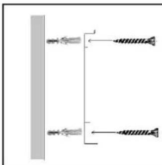
natural_image
Pure electrical circuit lines without any symbols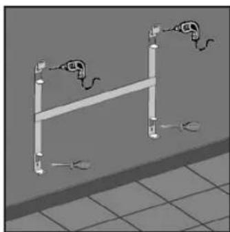
natural_image
Diagram of a horizontal pipe with two connected electrical meters, placed on a tiled floor (no text or symbols)natural_image
3D rendering of a metal structural frame with two vertical supports and a horizontal beam (no text or symbols)fig. 4
natural_image
3D diagram of a horizontal beam supported by two vertical posts, with no visible text or symbols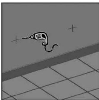
natural_image
Simple line drawing of a tool on tiled floor with plus signs above (no text or symbols)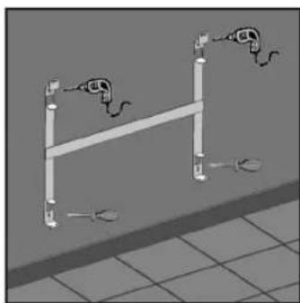
natural_image
3D diagram of a horizontal pipe with two connected electrical meters above it, placed on a tiled floor (no text or symbols)fig. 1 fig. 2 fig. 3
natural_image
3D rendering of a metal structural frame with two vertical supports and a horizontal beam (no text or symbols)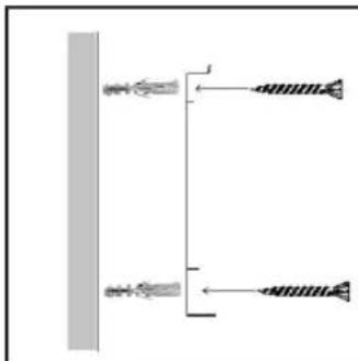
natural_image
Pure electrical circuit lines without any symbolsINSTALLING YOUR HEAT RADIATOR

Installing your Heat Radiator
The location of your heat radiator should be chosen properly and must follow any existing rules and regulations.
WARNING
■The appliance should never be covered by clothes, coverings or any other object, nor should it be placed below a wardrobe or any other obstacle for the circulation of hot air.
■The appliance should stay clear of all flammable objects and children should not be left alone close to the heater without adult supervision.
■Do not install the appliance below an electric outlet.
■Do not use the Heat Radiator to dry clothes.
■ To avoid overheating, do not cover the heating appliance.
■The appliance should not be installed near places which are at risk of splashing water like baths, washbasins, etc..
If the power cord is damaged, it may only be replaced by a technical service assistant, in order to avoid risks.
■The appliance should be installed so that the outlets, thermostats, mobile connection plug may not be touched directly or indirectly by any person within a bath or shower him with (respecting the limits set by the RBT regulations).
■Always follow the safety measures: the minimum distances between the Heat Radiator and the ground or a wall is 150 mm.

Installation Instructions
Wall mount:
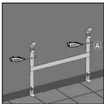
Always try to install the radiator onto an external wall (cold) under a window, but never in a ventilated area. Follow the minimum safety distances for installation.
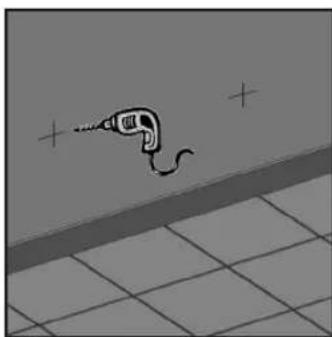
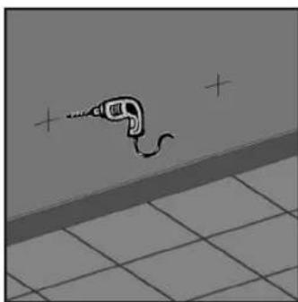
- Place the wall mount on the ground in the position in which it is to be mounted and mark the wall through the upper drill hole of the support on both sides. (fig. 1)
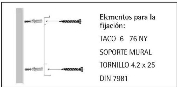
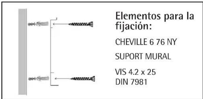
- Drill through the marks and insert a screw anchor. (fig. 2)
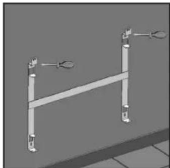
- Mount the support, making sure to align the lower screw holes, then drill. (fig. 3)
- With the mount fixed below, repeat step 2. (fig. 3)
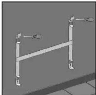
- Finally, screw on to properly fasten the support. (fig 4)
natural_image
3D diagram of a horizontal beam supported by two vertical posts, with no visible text or symbols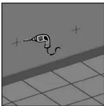
natural_image
Simple line drawing of a tool on tiled floor with plus signs above (no text or symbols)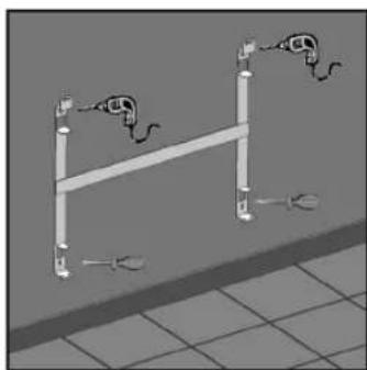
natural_image
3D illustration of a horizontal pipe with two connected fixtures, no text or symbols presentfig. 1 fig. 2 fig. 3
natural_image
3D rendering of a metal structural frame with vertical supports and mounting holes (no text or symbols)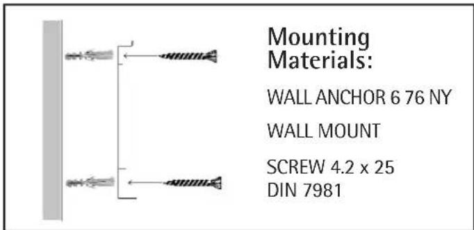
fig. 4

Safety Distances
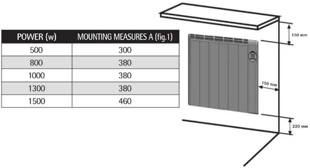
The radiator must be 150mm from all objects, walls... (see figure).
The distance from the floor must be 220 mm, which at the most may go down to 150 mm.
other
| POWER (w) | MOUNTING MEASURES A (fig.1) | |---|---| | 500 | 300 | | 800 | 380 | | 1000 | 380 | | 1300 | 380 | | 1500 | 460 | The image contains two tables: the top table shows a numerical value (e.g., 500) and the bottom table shows a physical dimension (e.g., 150 mm height, 220 mm width). The diagram includes a schematic of a solar panel with a scale indicator of 150 mm and 220 mm.
Series A: High Pressure Analogue Thermostat

Once the appliance is mounted and properly connected, rotate the upper knob to pressurise the Heat Radiator.
Rotate the thermostat knob to the right, and check to see that the pilot lights up, indicating that the Radiator is heating up.
Once the desired temperature is reached, turn the thermostat knob to the left until the pilot light switches off. After this the thermostat will regulate the room temperature to the setting selected.
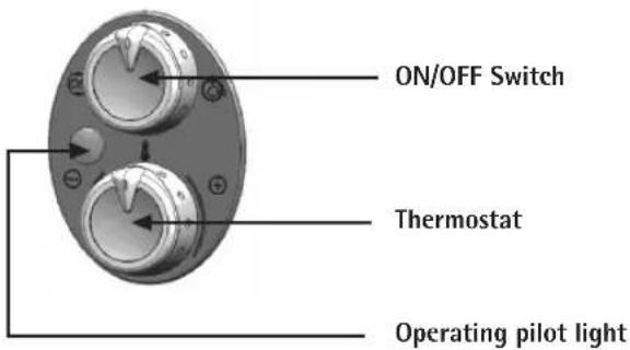
■ Consumption indicator light: Whenever the pilot light is on, the appliance is operating until it reaches the selected temperature.
■ Main Control Knob (ON/OFF Switch): to turn the radiator power on or off.
■Thermostat: it allows you to regulate the selected room temperature.
Anti-freeze Safety: by selecting the minimum thermostat setting (*), the temperature will stay at approximately 7°C. This will prevent freezing and save on heating costs (ideal for prolonged absences).
The control pilot light is on when the appliance is heating and otherwise it is off

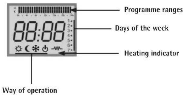
Series D: Digital Thermostat

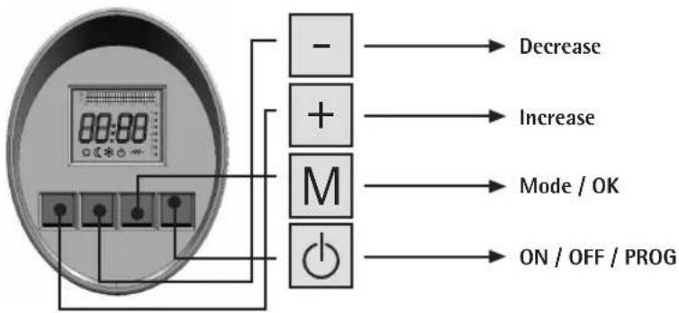
There are 4 buttons:
Once the appliance is mounted and properly connected, press the on button to pressurise the Heat Radiator.
Power On
Once turning the Heat Radiator on, the computer will recall the last user setting selected. In the first connection, the memory is empty, reason why the screen will blink constantly until any key is pressed.
Operating
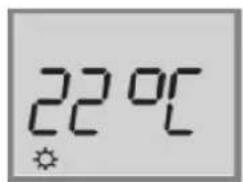
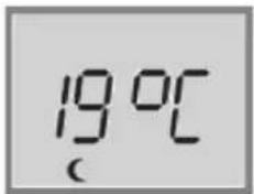
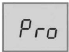
During operation, the thermostat indicates the user's selected temperature and displays the current operating mode:
COMFORT ECONOMY PROGRAMME OFF
natural_image
Simple gray square with a small black power button icon at the bottom (no text or symbols)
The -symbol is displayed while the resistance is operating.
Adjusting the comfort temperature
You can change the temperature by pressing the (+) and (-) buttons by 1°C per press. By maintaining the button pressed, the temperature will increase automatically by 1°C.
Once having selected the temperature and without any further presses, this temperature will be selected.
Selecting mode
Upon pressing the (Mode/ok), we can select the mode.
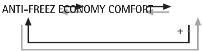
For each press greater than 0.1 seconds, the thermostat passes from one mode to the next: Comfort > Economy> Comfort ....
To select the "anti-freeze" mode, press (Mode/ok) for several seconds, until the screen with a * is displayed.
| MODE | SELECTED TEMPERATURE |
| COMFORT | Select with the (+) and (-) buttons |
| ECONOMY | Temperature less than 3°C |
| ANTI-FREEZE | 7°C |
| OFF | Off |

Programming
a. Make sure that the thermostat is in the STOP position or press the ON/STOP/WEEKLY PROGRAMMING to select STOP.
b. With a prolonged press (min. 5s) of the START/STOP/WEEKLY PROGRAMME button to select the Manual Programme mode.
c. Select the function mode by hour by pressing the "+" and "-" buttons and then "MODE/OK".
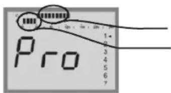
Upper segment: COMFORT
Lower segment: ECONOMY
Nothing: ANTI-FREEZE


d. Repeat the operation for each day of the week.
After programming day 7, the thermostat will automatically save all parameters and change modes at the selected time with Ensure that the time is correct. Change the time if necessary or validate it by pressing STOP.
Setting the clock
a. Make sure that the thermostat is in the STOP position or press the ON/STOP/WEEKLY PROGRAMMING to select STOP.
b. With a prolonged press (min. 5s) of the START/STOP/WEEKLY PROGRAMME button select the Manual Programme mode.
c. Short press the START/STOP/WEEKLY PROGRAMME button.
d. Select the day by pressing "+" and "-" and then press the "MODE/OK" button to validate.
e. Adjust the time by pressing the "+" and "-" buttons and press the "MODE/OK" button to validate.
Validation sets the STOP position.
Possible thermostat problems
■If the thermostat is below -15°C, the screen will display OC.
■If the thermostat is above 50°C, the screen will display SC.
Disposal of old electrical appliances
The European directive 2002/96/EC on Waste Electrical and Electronic Equipment (WEEE), requires that old household electrical appliances must no be disposed of in the normal unsorted municipal waste stream. Old appliances must be collected separately in order to optimize the recovery and recycling of the materials they contain, and reduce the impact on human health and the environment.
The crossed out "wheeled bin" symbol on the product reminds you of your obligation, that when you dispose of the appliance, it must be separately collected.
Consumers should contact their local authority or retailer for information concerning the correct disposal of their old appliance.
INSTALLATION DE L'ÉMETTEUR THERMIQUE

natural_image
3D diagram of a horizontal beam supported by two vertical supports, with no visible text or symbolsfig. 1 fig. 2 fig. 3
natural_image
Simple line drawing of a tool on tiled floor with plus signs (no text or symbols)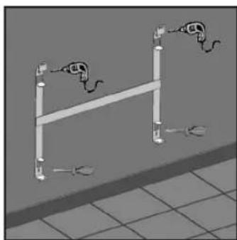
natural_image
3D diagram of a horizontal pipe with two connected cables, no text or symbols present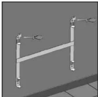
natural_image
3D rendering of a mechanical support structure with two vertical supports and a horizontal beam (no text or symbols visible)fig. 4
- Modelos
- INSTALLING YOUR HEAT RADIATOR
- WARNING
- Installation Instructions
- Wall mount:
- Safety Distances
- Series A: High Pressure Analogue Thermostat
- Series D: Digital Thermostat
- Power On
- Operating
- Adjusting the comfort temperature
- Selecting mode
- Programming
- Setting the clock
- Possible thermostat problems
- Disposal of old electrical appliances
- INSTALLATION DE L'ÉMETTEUR THERMIQUE
Brand : Orbegozo
Model : RCD-500
Category : Heating