
PGH465GM-N - Cooker PROLINE - Free user manual and instructions
Find the device manual for free PGH465GM-N PROLINE in PDF.


| Product Type | Freestanding Gas Cooker |
| Brand | Proline |
| Model | PGH465GM-N |
| Energy Source | Gas (Hob & Oven) |
| Number of Gas Burners | 4 |
| Oven Type | Gas Oven with Thermostat |
| Oven Capacity | Approx. 70 Liters |
| Ignition System | Auto Ignition (Battery-Powered) |
| Flame Failure Safety Device | Yes (On All Burners) |
| Grill Function | Gas Grill in Oven |
| Oven Door | Drop-Down Door with Glass Window |
| Timer | Mechanical Timer Included |
| Dimensions (W x D x H) | 60 cm x 60 cm x 85 cm (Approx.) |
| Weight | Approx. 50 kg |
| Color | Stainless Steel / Gray |
| Gas Type | Natural Gas (NG) - Convertible to LPG |
| Gas Connection | Rear Connection, 1/2" BSP Thread |
| Power Supply for Ignition & Timer | 1 x 1.5V AA Battery (Not Included) |
| Cleaning | Removable Oven Door, Enamel Interior |
| Safety Features | Flame Failure Device, Child Lock (Optional) |
| Accessories Included | Oven Shelf, Baking Tray, Grill Rack |
| Spare Parts Availability | Via Authorized Service Centers |
| Repairability Index | High (Standard Components) |
Frequently Asked Questions - PGH465GM-N PROLINE
User questions about PGH465GM-N PROLINE
0 question about this device. Answer the ones you know or ask your own.
Ask a new question about this device
Download the instructions for your Cooker in PDF format for free! Find your manual PGH465GM-N - PROLINE and take your electronic device back in hand. On this page are published all the documents necessary for the use of your device. PGH465GM-N by PROLINE.
USER MANUAL PGH465GM-N PROLINE
ORERATING AND INSTALLATION INSTRUCTIONS BUILT-IN GAS HOB

natural_image
Line drawing of a four-gas stove with four fans and three switches (no text or symbols)CONTENTS
- DESCRIPTION OF THE HOB
- SAFETY INSTRUCTIONS
- INSTALLATION
- USAGE
- MAINTENANCE & CARE
Dear Customer,
Thank you for purchasing this Proline Cooking Hob. The safety precautions and recommendations in these instructions are for your own safety and that of others. They will also provide a means by which to make full use of the features offered by your appliance.
Please keep this booklet in a safe place. It may be useful in future, either to yourself or to others in the event that doubts should arise relating to its operation.
This appliance must be used only for its intended purpose, that is for the domestic cooking of foodstuffs. Any other form of usage is to be considered as inappropriate and therefore dangerous.
The manufacturer declines all responsibility in the event of damage caused by improper or incorrect use of the appliance.
CE Declaration of conformity
- This cooking hob has been designed to be used only for cooking. Any other use (such as heating a room) is improper and dangerous.
- This cooking hob has been designed, constructed, and marketed incompliant with:
- Safety requirements of the "Gas" Directive 90/396/EC;
- Safety requirements of t"low voltage" Directive 2006/95/EC;
- Safety requirements of the "EMC" Directive 89/336/EC;
- Requirements of the Directive 93/68/EC.
CE GB

8
Descriptions:
- Ceramic glass
- Pan support
- Burner cap
- Burner body
-
Control knob
-
Rapid burner
- Semi-rapid burner
- Auxiliary burner
- Base cover
READ ALL IMPORTANT SAFEGUARDS AND ALL INSTRUCTIONS BEFORE USING THE APPLIANCE
The adjustment conditions for this appliance are stated on the rating label appliance shall be installed in accordance with the regulations in force and on in a well ventilated space. Read the instructions before using or installing this appliance. Appliances should be electrically reported problems due to improper connection are not covered by the warranty.
This appliance is not connected to a combustion product evacuation device. Particular attention shall be given to the relevant requirements regarding ventilation.
The use of a gas cooking appliance results in heat and moisture in the which it is installed. Ensure that the kitchen is well ventilated. Keep natural ventilation holes open or install a mechanical ventilation device (mechanical cooker hood). Prolonged intensive use of the appliance may call for adding ventilation, for example increasing the level of mechanical ventilation, where present.
While operating this appliance needs 2m3/hr air per kW heat input.
In the event of the burner flames being accidentally extinguished, turn of burner control and do not attempt to re-ignite the burner for at least one mo
Remove all the tape and packaging wrap before using the appliance. Do store any pressurised containers, such as aeresol cans, flammable materials, including paper, plastic and cloth items, in the drawer, near the surface.
Do not attempt for gas leakage with a flame.
All the operations including installation, fine tuning, transformations and the servicing operations must be carried out exclusively by qualified personnel.
CAUTION: The use of a gas cooking appliance results in the production of heat, moisture and products of combustion in the room in which it is installed. Ensure that the kitchen is well ventilated especially when the appliance is in use, keep natural ventilation holes open or install a mechanical ventilation device(mechanical extractor hood).
CAUTION: This appliance is for cooking purposes only. It must not be used for other purposes, for example room heating.
PRIOR TO INSTALLATION, ENSURE THAT THE LOCAL DISTRIBUTION CONDITIONS AND THE ADJUSTMENT OF THE APPLIANCE ARE COMPATIBLE.
This appliance must be installed by a qualified gas installer who must also be a qualified electrician if the appliance requires connecting to a mains electricity supply.
After removing the packaging material from the appliance and its accessories ensure that the hob is not damaged. If you suspect any damage do not use appliance and contact a qualified technician immediately.
This built-in hob is to be inserted into a cut out of a worktop. It will be electrically connected with the mains socket below counter level especially provided for this purpose. In all other respects, the user of the appliance is also liable for the orderly installation and operation - in confirmity with these instructions - according to the Appliances Safety LawAnd TheApplicable Regulations and Prescriptions.
Locating Your Built-in Hob
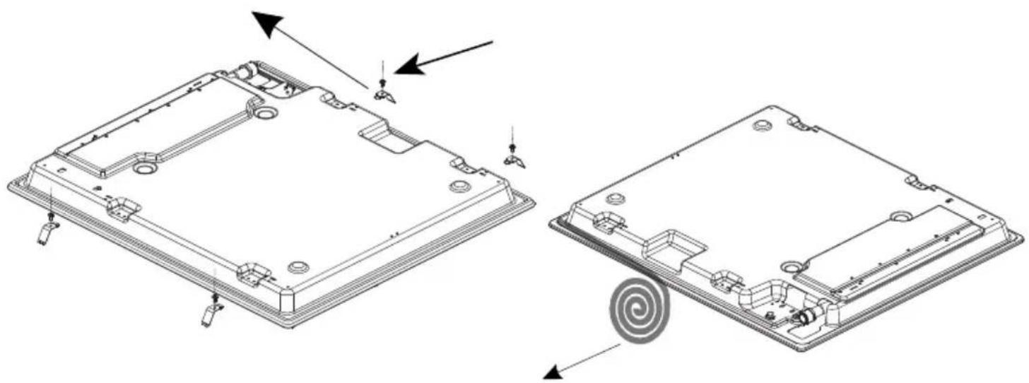
The Hob is supplied with a special seal in order to avoid any liquid infiltration in the work top. Cut out an opening in the top of your kitchen unit that corresponds to the measurements given in figure. Apply the self adhesive seal to all edges of the and carefully fit the hob into the opening in such a way that the knobs will be right side.
The leaf springs located on the lower left and right sides of the hob will fix the hob in the opening.
Create a space to install your hob , following the dimensions indicated or
- 100 mm from edge of cooker to combustible materials.
- 700mm underside of overhead cupboards, shelving
- 750mm underside of overhead exhaust fans.
This appliance must be installed according to the manufacturers installing instructions, local building regulations, gas authority codes and electrical wiring instructions.
Changing the Gas Inlet(FIGURE 1)
The gas feeding manifold protruding from the back of the hob must be completely, any means connection (nut,hose etc.)must be placed with attention avoid any contact with parts that will heat up. It is highly recommended to be access to pipe connection, whilehole is in use or when the gas supply is op
During the gas connection process, the pipe of the appliance should be stationary, while the connected part (mechanical, LPG or NG nut) is fixed. Alw use the seals supplied in the spare set between the connection ‘A’ for flexible connection.
For connection of methane type gases (NG),
- Use B type connection in Spain, Italy, Portugal, Greece, France and Algeria use with flexible hose convection.
- Use C type connection in Letonia and Luxemburg for mechanical connection. This connection may also be optionally used in some areas in France, Alge Spain, Portugal and Italy.
- Use C type connection in Germany and Belgium with an additional ISO7/ISO228 adapter and Netherlands with an additional Besca adapter, supplied in the spare set. An example of usage is shown in E.
- For all types of gasing type connection in United Kingdom and Ireland, the flexible gas hose should neither pass behindven or be in contact with objects that may cause combustion.
IMPORTANT
- The appliance should be installed, regulated and adapted to function other types of gas by a QUALIFIED INSTALLATION ENGINEER.
- Failure to comply with this condition will render the guarantee .invalid
- The appliance must be installed by a gas installer who appears on the gas register.
- The appliance must be installed in compliance with regulations in force.
• Installation engineers must comply to current laws in force concerning ventilation and evacuation of exhaust gases.
• Always unplug the appliance before carrying out any maintenance or repairs - Minimum distance between the appliance and combustible premises must be 20 mm
- After the connection had been made as to be tested.
- This test can be done by applying a soapy liquid to the connection. No bubble should appear. If there are bubbles, check the connection joint and recheck it necessary.
- For all gas connections, make sure that the connection parts and gas deliver components are in accordance with local and international requirements.
DO NOT USE NAKED FLAME TO CHECK FOR GAS LEAKS

FIGURE 1
Table for the choice of the injectors
| Gas Category | LPG | NG | |||
| G31 | G30 | G20 | G25G30 | ||
| 28-30mbar | 28-30/37mbar | 50mbar | 20 mbar | 25 mbar | |
| RAPID BURNER | |||||
| Injector diam.(%mm) | 85 | 85 | 75 | 115 | 125 |
| NominalRating (kw) | 3 | 3 | 3 | 3 | 3 |
| Min.Rating(kw) | 0.85 | 0.85 | 123 | 0.7 | 0.82 |
| Consumptionin1h | 218.13 gr/h | 214.28gr/h | 218.13gr/h | ||
| Consumptionin 1h(at 15°C and 1013mbar press) | 285.7lt/h | 3322lt/h | |||
| AUXILLARY BURNER | |||||
| Injector diam.(%mm) | 50 | 50 | 43 | 72 | 72 |
| NominalRating (kw) | 1 | 1 | 1 | 1 | 1 |
| Min.Rating (kw) | 0.4 | 0.4 | 0.5 | 0.3 | 0.3 |
| Consumptionin1h | 72.71 gr/h | 71.42gr/h | 72.71 gr/h | ||
| Consumptionin1h(at 15°C and 1013mb arpress) | 95.24lt/h | 110.74 lt/h | |||
| MEDIUM BURNER | |||||
| Injector diam.(%mm) | 65 | 65 | 58 | 97 | 94 |
| NominalRating (kw) | 1.75 | 1.75 | 1.75 | 1.75 | 1.75 |
| Min.Rating(kw) | 0.65 | 0.65 | 0.65 | 0.495 | 0.495 |
| Consumptionin 1h | 127.25 gr/h | 125gr/h | 127.25gr/h | ||
| Consumptionin1h(at 15°C and 1013mb arpress) | 166.66lt/h | 193.79lt/h | |||
NOTE;
Instructions for gas conversion can be found on page 13.
LOCATION
The appliance may be installed in a kitchen, kitchen/diner or a bed sitting room, but not in a room or space containing a bath or a shower.
The appliance must not be installed in a bed-sitting room of less than 20 ^3 m .
The appliance is designed and approved for domestic use only and should not be installed in a commercial, semi commercial or communal environment. Your product will not be guaranteed if installed in any of the above environments and could affect any third party or public liability insurances you may have.
VENTILATION REQUIREMENTS
The appliance should be installed into a room or space ith an air supply in accordance with BS 5440-2:2000.
For rooms with a volume of less than 5 m^3 - permanent ventilation of 100 mm^2 free area will be required.
For rooms with a volume of between 5 m^3 and 10 m^3 a permanent ventilation of 50 cm^2 free area will be required unless the room has a door which opens directly to the outside air in which case no permanent ventilation is required.
For rooms with a volume greater than 10 m - no permanent ventilation is required.
NB. Regardless of room size, all rooms containing the appliance must have direct access to the outside air via an openable window or equivalent.
Where there are other fuel burning appliances in the same room, BS 5440 2:2000 should be consulted to determine the correct amount of free area ventilation requirements.
The above requirements allow use of a gas oven and grill but if there are other gas burning appliances in the same room, consult a qualified engineer.
Locating the built-in hob
![523mm 594mm 43.5mm Min. 25mm Min. B 560mm 490mm Min. 100mm Neigboorhood walls A [mm] B [mm] Combustible 60 150 Non-combustible 40 50](/content/2026/05/968244/images/8d7ef033e0980c883d75e30d85baa13467c70cc607911de4d33fb0500795ae66.jpg)
natural_image
Technical line drawing of two views of an electronic device casing with mounting holes and internal components (no text or symbols)ELECTRICAL CONNECTION
Before proceeding with the electrical connection verify that :
- The current carrying capacity of the system and the socket is adequate for maximum power rating of the hob.
• The voltage indicated on the capacity label is the same as the supply volta
- Do not use for connection any reductions, adapters or shunts because they cause overheating.
• The socket has an earth terminal.

Please ensure that the voltage on the capacity label is the same as the sup voltage before connection is made.
The appliance is provided with supply cord and a plug. Replacement of the r cable must be carried up by you to be electrician
before each maintenance. Follow reconnection diagrams strictly. The protective earth connection (PE) must be connected to the Terminal marked (). During installation, please ensure that isolated cables are used.
ELECTRICAL CONNECTION (UK ONLY)
For your safety please read the following information Warning: This appliance must be earthed.
The appliance must be connected to a 240 volts 50 cycle AC supply b means of a three pin socket, suitably earthed and should be protected a 3 amp fuse in the plug.
The appliance is supplied with a 13-amp 3-pin mains plug fitted with a amp fuse. Should the fuse require replacement, it must be replaced with fuse rated at 3 amp and approved to BS1362
The plug contains a removable fuse cover that must be refitted when t fuse is replaced. In the event of the fuse cover being lost or damaged plug must not be used until a replacement cover has been obtained. If the mains plug is unsuitable for the socket outlet in your home or is removed for any other reason, then the fuse should be removed and th cut off plug disposed of safely to prevent the hazard of electric shock.
There is a danger of electric shock if the cut off plug is inserted into any 13 amp socket outlet.
How to wire a 13 amp plug Important
The wires in the mains lead on this appliance are coloured in accordance with the following code :
Green and Yellow – Earth
Blue - Neutral
Brown - Live

As the colours may not correspond with the markings identifying the term in your plug proceed as follows.
The green and yellow wire must be connected to the terminal in the p which is marked with the letter E, or with the earth symbol or coloured and yellow.;
The blue wire must be connected to the terminal marked N.
The brown wire must be connected to the terminal marked L.
4.1 Usage of Your Gas Burners
Manual Ignition
To ignite one of the burners, approach a match to its upper circumference push the corresponding control knob and turn it counter clock-wise. Medium regulation of the flame will be obtained by turning the control knob between maximum position (big flame) and the minimum position (small flame).
The small diagrams situated on the control panel indicate to the gas burner use.
Ignition Through Control Knob (microswitch):
Press the hob valve you want to operate and turn the control knob in the clockwise direction. The microswitch placed under the knob will automatically create sparks through the spark plug of the burner. Continue pressing the k until you see a stable flame on the burner.
Recommendations:
Your hob is composed with of burners different diameters. The most econor way of using gas is too choose the corresponding gas burners for your copan size and to bring the flame to minimum position once the boiling point reached. It is recommended to always cover your cooking pan.
In order to obtain maximum performance from the burners, use pots with the following flat bottom diameters.
Rapid Burner : 22-26 cm
Medium Rapid Burner : 14-22 cm
Auxiliary Burner : 10-18 cm

natural_image
Two simple line drawings of a cooking pot with flames and a lid, no text or symbols present.Do not use over or under sized pans or pans that do not have flat bases.
WARNING:
The use of under sized pans causes flames to rise up the sides of the pans causing the handles to get very hot.
GAS CONVERSIONS
Transformation For The Gas Cookers Replacement Of Injectors
GAS CONNECTION
The installation of the gas appliance to natural gas or LPG must be carried out by a gas safe registered engineer.
Engineers shall take due account of the provisions of the relevant BritishStandards Code of practice, the gas safety regulations and the building standards (Scotland) (Consolidation) regulations issued by the Scottish development department.
The gas burners adapt to different types of gas, by replacing the corresponding injectors to gas on use.
There fore it is necessary to;
- Cut off the feeding gas flow and electric current.
- Remove the cap and the adapter.
- Unscrew the injectors.
- Replace the injector with the ones corresponding to the type of gas that is going to be used, according to the information on the transformation chart.

INJECTORS REPLACEMENT OF HOB BURNERS
This appliance is manufactured for conversion to LPG. To purchase an LPG conversion kit, contact the store where you purchased this appliance. The diameter is marked on the injector in cents of millimetre.
Select the injectors to be replaced according to the "Table for the choice of injectors". To replace the injectors: Remove pan-supports and burners from the hob top. Using a spanner, remove the injector from its housing and replace it the proper one according to the kind of gast(see "Table for the choice of injectors").
Adjusting The Reduced Flame Position
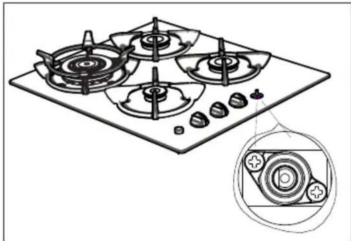
For reduced flame position the by pass screw must be loosened in transformation from LPG to NG. In transformation from NG to LPG, the san screw must beightened.
- Make sure that the appliance is unplugged from the electric current and the feed is open.
- Ignite the burners and leave them on in minimum position.
- Remove the knobs and rubber seals because the screws are accessible on when the knobs and the seals are removed.
- This procedure must be repeated of the valves.
natural_image
Line drawing of a four-gas stove with a close-up inset showing internal components (no text or symbols)
natural_image
Exploded view diagram of a mechanical assembly with multiple circular components and no visible text or symbols- With the help of a small screwdriver fasten or loosen the by pass screw b which makes the flame of the burner reduce to the minimum.
When the flame has a length of at least 4 mm, the gas is well distributed. Make sure that the flame does not die out when passing from the maximum position to the minimum position.
After the adjustment is complete replace the rubber seal and replace the kn
Disconnecting:
Before cleaning disconnect the hob from the electricity supplying the main gas supply.
Burner Caps:
Periodically, enamelled pan supports, enamelled covers, burner heads must be washed with soapy warm water rinsed and dried.
After drying them thoroughly, replace them correctly in their placement.
Pan Supports:
In order to keep them a new, it is necessary to clean them frequently with warm soapy water and then dry with a soft tissue. Do not wash them while I and never use abrasive powders or abrasive cleaning materials. Do not leave vinegar, coffee, milk, salt, water, lemon, or tomato juice to remain in contact with enamelled parts for long periods of time.
CLEANING THE CERAMIC GLASS SURFACE
- Before you begin cleaning make, sure the appliance is switched off and cool down
- Remove spillages and incrustations with a scrapscraper available separately contact the store where you purchased this appliance
- Dust or food particles can be removed with a dampened cloth.
- Clean the glass surface with warm water and mild detergent, do not use aggressive or abrasive cleaners, as they will damage the surface.
- All traces of the cleaner MUST be removed with a damp cloth and then a one.
- Boiled over Fat and Liquids from food must be removed immediately to avoid damage to the surface. If they are allowed to harden they become increasing difficult to remove. This is especially true in the case of sugar, yrup mixtures that could permanently pit the surface of the appliance if left to burn on. If Plastic, sugar, syrup or similar substance, has melted onto the appliance surface, it must be removed with a scraper immediately (whilst the surface is still hot) to avoid permanent damage.
- Do not use knives, steel wool or abrasive sponges to clean the appliance, a these products will result in damage to the surface.
- Remove the control knobs to clean in warm soapy water, take care not to damage the seals underneath the control knobs.
- DO NOT use a steam cleaner as water ingress will result in internal damage voiding the warranty.
If something doesn't seem to work
If there is something about your appliance which you do not understand and you live in the UK you can phone our help line during normal hours on: 0844 8009595 If you require service, call the number on your sales receipt.
Calls are charged at standard rates.
We apologise for any inconvenience caused by minor inconsistencies in these instructions, which may occur as a result of product improve and development.
Kesa U.K HU1 3AU 01/06/2010
PROLINE
PGH465GM-N
BEDIENING EN INSTALLATIE INSTRUCTIES INGEBOUWDE
GAS. 22.3/\$A7

natural_image
Line drawing of a four-gas stove with four fans and three stoves, no text or symbols presentINHOUD
- BESCHRIJVING VAN DE KOOKPLAAT
- VEILIGHEIDSINSTRUCTIES
- INSTALLATIE
- HET IN GEBRUIK NEMEN VAN DE KOOKPLAAT
- ONDERHOUD AAN HET APPARAAT
Beste klant,
Beschrijvingen:
- Keramisch glas
- Pandragers
- Branderdop
- Toestel
-
Bedieningsknop
-
Grote brander
- Kleine brander
- Hulpbrander
- Basisdeksel
LEES ALLE BELANGRIJKE VEILIGHEIDSMAATREGELEN EN ALLE INSTRUCTIE VOOR U HET TOESTEL IN GEBRUIK NEEMT
AFBEELDING 1
natural_image
Technical line drawing of two electronic components with mounting holes and a circular component, showing assembly or assembly motion (no text or symbols)natural_image
Three cooking pots on stovels with a crossed-out heating pan symbol (no text or labels)natural_image
Hand using a tool to press or install a component on a circular base (no text or symbols visible)DE INJECTOREN VAN DE BRANDERS VERVANGEN
natural_image
Line drawing of a four-gas stove with fan and wheels, shown with an inset close-up of the internal components (no text or symbols)
natural_image
Exploded view diagram of a mechanical assembly with multiple circular components and no visible text or symbols


- ORERATING AND INSTALLATION INSTRUCTIONS BUILT-IN GAS HOB
- CONTENTS
- Dear Customer,
- CE Declaration of conformity
- Descriptions:
- READ ALL IMPORTANT SAFEGUARDS AND ALL INSTRUCTIONS BEFORE USING THE APPLIANCE
- PRIOR TO INSTALLATION, ENSURE THAT THE LOCAL DISTRIBUTION CONDITIONS AND THE ADJUSTMENT OF THE APPLIANCE ARE COMPATIBLE.
- Locating Your Built-in Hob
- Changing the Gas Inlet(FIGURE 1)
- IMPORTANT
- DO NOT USE NAKED FLAME TO CHECK FOR GAS LEAKS
- NOTE;
- LOCATION
- VENTILATION REQUIREMENTS
- Regardless of room size, all rooms containing the appliance must have direct access to the outside air via an openable window or equivalent.
- Locating the built-in hob
- ELECTRICAL CONNECTION
- ELECTRICAL CONNECTION (UK ONLY)
- For your safety please read the following information Warning: This appliance must be earthed.
- How to wire a 13 amp plug Important
- Usage of Your Gas Burners
- Manual Ignition
- Ignition Through Control Knob (microswitch):
- Recommendations:
- GAS CONVERSIONS
- Transformation For The Gas Cookers Replacement Of Injectors
- GAS CONNECTION
- INJECTORS REPLACEMENT OF HOB BURNERS
- Adjusting The Reduced Flame Position
- Disconnecting:
- Burner Caps:
- Pan Supports:
- CLEANING THE CERAMIC GLASS SURFACE
- If something doesn't seem to work
- Calls are charged at standard rates.
- PROLINE
- PGH465GM-N
- BEDIENING EN INSTALLATIE INSTRUCTIES INGEBOUWDE
- 22.3/\$A7
- INHOUD
- Beste klant,
- Beschrijvingen:
- LEES ALLE BELANGRIJKE VEILIGHEIDSMAATREGELEN EN ALLE INSTRUCTIE VOOR U HET TOESTEL IN GEBRUIK NEEMT
- DE INJECTOREN VAN DE BRANDERS VERVANGEN
Brand : PROLINE
Model : PGH465GM-N
Category : Cooker