SAC10544DE - Air conditioner Simplicity - Free user manual and instructions
Find the device manual for free SAC10544DE Simplicity in PDF.


| Product Type | Room Air Conditioner |
| Brand | Simplicity |
| Model | SAC10544DE |
| Cooling Capacity | 10,500 Btu/h |
| Input Wattage | 970 W |
| Energy Efficiency Rating (EER) | 10.8 |
| Fan Speeds | 3 (High, Medium, Low) |
| Cooling Speeds | 3 |
| Cooling Area Coverage | 450 sq. ft. |
| Noise Level | 53 dB |
| Unit Dimensions (W x D x H) | 22" x 24.25" x 14.75" |
| Shipping Weight | 108 lb |
| Voltage / Frequency | 115 V / 60 Hz |
| Window Kit Maximum Width | 40" |
| Window Kit Minimum Width | 28" |
| Window Kit Minimum Height | 17.8" |
| Controls | Electronic with LED display |
| Timer | Auto start/stop 0-12 hours |
| Energy Saver Mode | Yes (fan cycles with compressor) |
| Swing (Oscillation) | Yes |
| One Touch | Pre-set 22°C (71.6°F) |
| Air Filter Indicator (E1) | Yes (cleaning reminder) |
| Fresh Air Ventilation | Yes (open/close) |
| Installation Type | Window (single/double hung) – NOT for through-wall |
| Warranty | 2 years parts (including sealed system); 3 additional years on sealed system |
Frequently Asked Questions - SAC10544DE Simplicity
User questions about SAC10544DE Simplicity
0 question about this device. Answer the ones you know or ask your own.
Ask a new question about this device
Download the instructions for your Air conditioner in PDF format for free! Find your manual SAC10544DE - Simplicity and take your electronic device back in hand. On this page are published all the documents necessary for the use of your device. SAC10544DE by Simplicity.
USER MANUAL SAC10544DE Simplicity
For service, contact your nearest service depot or call:
1-800-263-2629
The model number of your room air conditioner is found on the serial plate located on the right side of the unit above the power cord.
All repair parts are available for purchase or special order when you visit your nearest service depot. To request service and/or the location of the service depot nearest you, call the TOLL FREE NUMBER: 1-800-263-2629
When requesting service or ordering parts, always provide the following information:
- Product Type
- Model Number
- Part Number
- Part Descript
- Part Description
Read and Follow All Safety Rules and Operating Instructions Before First Use of This Product.
PRÉCAUTION:
natural_image
Front view of a simple electric air conditioner unit with a digital display and control panel (no visible text or symbols)Simplicity\*
Room Air Conditioner
Table of contents 1
Simplicity\*
Table of contents 15

Danby Products Limited, Guelph, Ontario Canada N1H 6Z9
Danby Products Inc., Findlay, Ohio USA 45840
Danby Products Limited, Guelph, Ontario Canada N1H 6Z9
Danby Products Inc., Findlay, Ohio USA 45840

bar
| Category | Value | |---|---| | A | 100 | | B | 100 |Simplicity
GARANTIE LIMITÉE DE CLIMATISEUR
Danby Products Limited
PO Box 1778, 5070 Whitelow RD, Guelph, Ontario, Canaco NIH 629
Telephone: (519) 837-0920 FAX: (519) 837-0449
01/01
Danby Products Inc.
PO Box 669, 101 Bentley Court, Findlay, Ohio, U.S.A. 45840
Telephone: (415) 425-8627 FAX: (415) 425-8629
TABLE OF CONTENTS
| Page | |
| Introduction | 2 |
| Unit Specifications | 2 |
| Electrical Specifications | 3 |
| Energy-Saving Tips | 4 |
| Window Installation | 4 |
| Operating Instructions | 11 |
| Care and Maintenance | 12 |
| Trouble Shooting Guide | 13 |
| Warranty | 14 |
Parts Identification

INTRODUCTION
Thank you for choosing a Simplicity Room Air Conditioner to cool your home. This Use and Care Manual provides information necessary for the proper care and maintenance of your new Room Air Conditioner. If properly maintained, your air conditioner will give you many years of trouble free operation. To avoid installation difficulties, read these instructions completely before installing/operating your unit.
NOTE: This unit is NOT designed for through-the-wall installation.
For easy reference, you may want to attach a copy of your sales receipt to this page. Note following information provided (on the manufacturer's nameplate located on the right side of the unit above the power cord). This information will be needed when you contact a Customer Service Representative.
Model Number: ____
Serial Number: ____
Date of Purchase: ____
Dealer's Name and Address: ____
Refer to the trouble shooting section of this Use and Care Manual if the unit is not operating correctly. If these suggestions do not solve the problem, contact an authorized service representative or call Danby TOLL FREE: 1-800-263-2629
Keep these instructions for future reference. This symbol denotes a caution or warning

CAUTION
Do not leave a room air conditioner unattended in a space where people or animals who cannot react to a failed unit are located. A failed unit can cause extreme overheating or death in such an enclosed, unattended space.
| Model No.Unit Specificafications | SAC7304D | SAC8404DE | SAC10544DE | SAC12304D | |
| Voltage | 115V/60Hz | 115V/60Hz | 115V/90Hz | 115V/60Hz | |
| Cooling Capacity (Btu/h) | 7,300 | 8,400 | 10,500 | 12,000 | |
| Input Wattage | 740 | 780 | 970 | 1170 | |
| Energy Efficiency Rating (EER) | 9.8 | 10.8 | 10.8 | 9.8 | |
| Fan/Cooling Speeds | 3/3 | 3/3 | 3/3 | 3/3 | |
| Cooling Area Coverage (Sq.ft.) | 270 | 360 | 450 | 500 | |
| Noise Level (dB) | 49 | 55 | 53 | 56 | |
| Unit Dimensions | Width | 17.75" | 22" | 22" | 22" |
| Depth | 22.5" | 24.25" | 24.25" | 24.25" | |
| Height | 13.5" | 14.75" | 14.75" | 14.75" | |
| Window Kit Dimensions | Maximum Width | 37" | 40" | 40" | 40" |
| Minimum Width | 24.5" | 28" | 28" | 28" | |
| Minimum Height | 15.5" | 17.8" | 17.8" | 17.8" | |
| Shipping Weight | 97 lb | 108 lb | 108 lb | 108 lb | |
NOTE: Specifications are subject to change without notice for further improvement.
GUIDE DE DÉPANNAGE
- All wiring must comply with local and national electrical codes and must be installed by a qualified electrician. If you have any questions regarding the following instructions, contact a qualified electrician.
- Check available power supply and resolve any wiring problems BEFORE installing and operating this unit.
- This 115V air conditioner uses 12.0 or less nameplate amps and may be used in any properly wired, general purpose household receptacle. See Table 1 for specifications for individual branch circuit.
- For your safety and protection, this unit is grounded through the power cord plug when plugged into into a matching wall outlet. If you are not sure whether your wall outlet is properly grounded, please consult a qualified electrician.
- The wall outlet (3-pin) must match the plug (3-pin) on the service cord supplied with the unit. DO NOT use plug adapters. See Table 2 for receptacle and fuse information. If it is necessary to use an extension cord to connect your air conditioner, use an approved "air conditioner" extension cord only. (available at most local hardware stores)
- The rating plate on the unit contains electrical and other technical data. The rating plate is located on the right side of the unit, above the power cord.
| Table 1: Suggested Individual Branch Circuit | |
| Nameplate Amps 5.0 to 12 | AWG Wire Size* 14 |
| AWG- American Wire Gage * Based on copper wire at 60 °C temperature rating. | |
| Table 2: Receptacle and Fuse Types | |
| Rated Volts | 125 |
| Amps | 15 |
| Wall Outlet | |
| Fuse Size | 15 |
| Time Delay Fuse (or circuit breaker) | Plug Type |
ENERGY-SAVING TIPS
Your Room Air Conditioner unit is designed to be highly efficient in energy savings.. Follow these recommendations for greater efficiency.
- Select thermostat setting that suits your comfort needs and leave thermostat at that chosen setting.
- The air filter is very efficient in removing airborne dust particles. Always keep the air filter clean.
- Use drapes, curtains, or shades to keep direct sunlight from heating room, but DO NOT obstruct the air conditioner. Allow air to circulate around the unit without obstruction.
WINDOW INSTALLATION

-ELECTRIC SHOCK HAZARD
To avoid the possibility of personal injury, disconnect power to the unit before installing or servicing.
Tools Needed for Window Installation
Screw Drivers: Both Phillips and flat head Power Drill: 1/8 inch diameter drill bit
Pencil
Measuring Tape Scissors
Carpenters Level Adjustable Wrench

CAUTION

To avoid installation/operation difficulties, read these instructions thoroughly.
Your Room Air Conditioner is designed for easy installation in a single or double-hung window. NOTE: This unit is NOT designed for vertical (slider type) windows and/or through-the-wall applications. NOTE: Save the shipping carton and packing materials for future storage or transport of the unit. Remove from carton, the plastic bag containing the installation hardware kit necessary for the installation of your air conditioner. Please check the contents of hardware kit against the corresponding model check list, prior to installation of the unit. See Fig. 1
Fig. 1 Installation Hardware Model


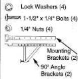
INSTRUCTIONS DE FONCTIONNEMENT
Because the compressor is located on the controls side of the unit (right side), this side will be heavier and more awkward to manipulate. Inadequate support on control side of the unit can result in personal injury and damage to your unit and property. Therefore, it is recommended to have someone assist you during the installation of this unit.
Your unit is designed to evaporate condensation under normal conditions. However, under extreme humidity conditions, excess condensation may cause basepan to overflow to the outside.
The Unit should be installed where condensation run-off cannot drip on pedestrians or neighboring properties.
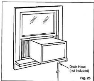
A drain tube connection (excluding hose) is provided to redirect condensation overflow. See Fig. 25.
1. Select the Best Location
A. This room air conditioner is designed to fit easily into a single or double hung window. However, since window designs vary, it may be necessary to make some modifications for safe, proper installation.
B. Make sure window and frame is structurally sound and free from dry and rotted wood.
C. For maximum efficiency, install the air conditioner on a side of a house or building which favors more shade than sunlight. If the unit is in direct sunlight, it is advisable to provide an awning over the unit.
D. Provide sufficient clearance around the cabinet to allow for ample air circulation through the unit. See Fig. 2. The rear of the unit should be outdoors and not in a garage nor inside a building. Keep unit as far away as possible from obstacles/obstructions and at least 30^ above the floor or ground. Curtains and other objects within a room should be prevented from blocking the air flow.
E. Be certain the proper electrical outlet is within reach of the installation. Use only a single outlet circuit rated at 15 amps. All wiring should be in accordance with local and national electrical codes.
F. DO NOT USE "REGULAR" EXTENSION CORDS WITH THIS UNIT. If it is necessary to use an extension cord to connect your air conditioner, use an approved "air conditioner" extension cord only. (available at most local hardware stores)
G. DO NOT install unit where leakage of combustible gas is suspected. Your air conditioner may fail to operate in air containing oils (including machine oils), sulfide gas, near hot springs, etc...

-
Preparation to Remove the Air Conditioner Slide-Out Chassis (All Models)
-
Position the air conditioner in the normal (upright) position.
- Remove the air filter by grasping the filter handle (on front grill) and sliding it to the right. Fig. 2
- Remove the phillips screw (behind filter) securing the grill front to the chassis. (Fig. 4)
- Remove the phillips screws located on the (lower left/right) edge of front grill. (Fig.3)
- To remove the front grill, grasp the lower front corner of the grill, pulling (gently) outward and upward. (Fig.5)
Repeat this step on the 3 remaining corners. - Before the front grill can be completely removed from the cabinet, it will be necessary to disconnect the (male/female) electrical wire harness located directly behind the front grill. (Fig 5a)
- Remove the two phillips screws (lower left/right side of cabinet) securing the slide-out-chassis to the cabinet. Fig.7
NOTE: These screws must be reinstalled upon completion of the window installation. (to secure slide-out-chassis)
NOTE: Some models may be inclusive of an additional (slide-out chassis) retaining bracket and screw located at the front of the chassis. This bracket and screw must also be removed before attempting to remove the slide-out chassis. Fig. 6
NOTE: This bracket and screw does not have to be reinstalled upon completion of the window installation.
- Grasp the pull handle at the front of the slide-out-chassis and carefully slide the air conditioner out of the cabinet. (Fig.6) Please seek assistance for this procedure.
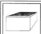
Fig. 1
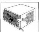
Fig. 2

Fig. 3
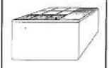
Fig. 4

Fig. 5a
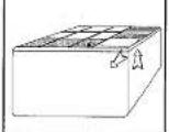
Fig. 5

natural_image
Diagram of a 3D box with ventilation grilles and internal structure, labeled Fig. B (no text or symbols on the diagram itself)
-
Assembly of the Upper & Lower Channels, to Cabinet. (All Models)
-
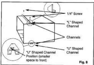
"L" Shaped Top Channel: Install the "L" shaped channel to the top of the cabinet as shown in Fig. 8 using four (4) 1/4" screws.
- "U" Shaped Bottom Channel: Install the "U" shaped channel to the bottom of the cabinet as shown in Fig. 8 using four (4) 1/4" screws. NOTE: Some models may already have the bottom channel factory installed.
- Assembly of the Side Curtains to Cabinet. (All Models)
- Slide the shutters into the top and bottom channels as shown in Fig. 9. The shutters are identified (on frame) as left & right. Attach the shutters to the cabinet using four 1/4" screws on each side.
- Installation of Mounting Brackets and First Sealing Strip (All Models)
SPECIAL NOTE: Windows come in a variety of different designs and styles. Therefore, it may be necessary to modify or improvise on your particular installation.
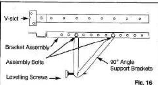
A. Attach the bracket assembly to the 90° angle support brackets (Fig. 16) using four 1 1/2" x 1/4" bolts. (two bolts per bracket) Secure with the four 1/4" lock washers and four 1/4" nuts. DO NOT immediately tighten these bolts as it may be necessary to adjust the depth of the bracket assembly, depending on the depth of your window sill. See Fig. 18 & 19. Test the bracket assembly in the window before installing, if satisfied, tighten all bolts. Install the two levelling screws into the 90° support brackets. See Fig. 16 If the levelling screws are distanced too far away from the wall to provide adequate stability, it may be necessary to shim this area with a solid piece of wood. See Fig. 19.
B. Measure the length of the inside sill and find the center as shown in Fig. 17. Models: SAC7304D: Measure 8.071" on each side of center and mark these points.
Models: SAC8404DE & SAC10544DE&
SAC12304D: Measure 10.315" on each side of center and mark these points. Align the V-slot on the bracket with each corresponding mark and mount the brackets to the sill using two 3/4" screws & two flat washers per bracket.
Brackets should be perpendicular to the inside window sill, with step (U) bracket tight against the sill. See Fig. 18.
C. For proper condensation run-off it will be necessary to adjust the angle/pitch of the window brackets. This is accomplished by adjusting the distance of the leveling screw on the outer wall. The maximum angle/pitch should not exceed more than 3/16". See Fig. 18.


natural_image
Technical line drawing showing two mechanical components mounted on a platform with alignment arrows (no text or symbols)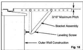


- Installation of the Cabinet (All Models)
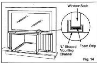
A. Place the air conditioner cabinet into the window with the "L" shaped mounting channel (on top) positioned in front of the upper window sash. The "U" shaped channel on the bottom of the cabinet should be positioned in the "recessed" portion of the track located at the front of the window brackets. Pull the window down until it rests just behind the front flange of the (top) "L" shaped mounting channel. See Fig. 14.
B. Align one hole in the bottom of the cabinet with one hole in the bracket assembly. Secure the cabinet to the bracket using a 1/4" screw provided. Repeat the same procedure on the opposite side of the cabinet. Fig. 15
C. Check to make sure the "pitch" (angle) of the cabinet is slanted slightly downward on the outside. If necessary, re-adjust the levelling screws in the mounting bracket. Fig. 18
D. Cut the first foam sealing strip to fit the underside (bottom) of the lower window sash. Remove the peel-off backing on the foam and attach the foam strip to the sash. See Fig. 13.

natural_image
Technical line drawing of a mechanical assembly with two vertical supports and diagonal lines (no text or symbols)natural_image
Diagram of a 3D box with internal structure and ventilation slots, labeled Fig. 6 (no text or symbols on the diagram itself)
- Installing the Slide-Out Chassis into Cabinet: (please seek assistance for this procedure)
- Carefully slide the air conditioner back into the cabinet. (in window)
Note: Ground wire must be re-installed before completing next step.
- Reinstall (slide-out-chassis) security screws removed earlier from the (lower left/right) side of the cabinet. Fig. 7
- Expand the shutter frames (fully) on each side and secure the top of the shutter frame to the window sash using one 3/4" screw & flat washer on each side. Fig. 23
-
Install a shutter clamp on each side of the (lower) shutter frame and secure to window sill using one 3/4" screw & flat washer on each side. Fig.23
-
Reinstalling Front Grill (All Models):
Before re-installing the front grill back on the cabinet, you must re-connect the (male/female) electrical wire harness between the front grill control panel and the main (cabinet) unit. (Fig.5a) Make sure the electrical connection is firmly and securely attached.
- Position the front panel on the cabinet starting at the top. The front panel lock tabs must be imported into the retaining slots in the cabinet.
- Repeat this procedure on all sides, making sure the fresh air ventilation lever arm and power cord are properly installed back to their original position on the front grill.
- Secure the front grill to the cabinet using the phillips screws removed earlier. Fig's. 3 & 4
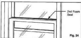
• Re-install the air filter. - Cut the second foam seal to fit the opening between the top inside and outside window. See Fig. 24.
- Some installations may require additional sealing around the window and air conditioner. Check for any air leaks and seal where necessary.
- Under very humid conditions, water removal may be excessive enough to overflow from the rear of the unit or increase noise levels of the air conditioner. If this occurs, you may want to attach a section of (garden) drain hose (not included) to the drain plug located at the rear of the unit, this will permit condensation to run off more conveniently. See Fig. 25.


7. Electronic Control Features
LED DISPLAY: The LED window displays the following information independently.
- Set Cooling Temperature
• Ambient Room Temperature
• Auto on/off Timer Programs
E1 = (Clean Air Filter)
NOTE: During normal operating conditions, (after all settings are complete) the LED readout will always default to show (display) the "ambient room temperature". In order to view the "set" temperature of the air conditioner, press either of the temperature
▲ key pads once.


POWER SWITCH: turns power on/off
SWING: Activates the automatic air swing (oscillation) feature.
(ENERGY SAVER): Press and hold the "SWING" keypad for 3 seconds to activate the ENERGY SAVER program. This program is designed to reduce energy consumption by limiting (restricting) operation of the fan motor with the operation of the compressor, i.c.
compressor off / fan off
compressor on / fan on
NOTE: When the ENERGY SAVER feature is not selected, the fan motor operates continuously, even after the compressor (cooling mode) has cycled off. i.e.
compressor on / fan on compressor off / fan on
MODE: Activates the FAN or COOLING mode.
TIMER: Activates the auto start or auto stop timer program from 0 \~ 12 hours. (1 hour increments)
ONE TOUCH: Activates a (factory) pre-set temperature setting of 22C (-/- - 2C) 71.6F.
FAN: Activates fan speed settings. (High, Medium, Low)
KEYPAD: Activates (increases) temperature settings.
▼ KEYPAD: Activates (decreases) temperature settings.


CAUTION

Walt three minutes before adjusting/changing temperature settings. Adjusting temperatures too quickly may cause the compressor overload to trip, resulting in a blown fuse.
Fresh Air Ventilation should be kept in the "closed" position during air conditioning mode. Fresh Air Ventilation should be kept in the "open" position during "fan mode" only when clearing smoke and/or odors from the room.

10

MISE EN GARDE

Press the POWER keypad to turn the unit on/off.
▲ TEMPERATURE SETTINGS:
Press the up keypad to increase the set (operating) temperature of the air conditioner. Each time the keypad is prossed the temperature is increased as follows; 2°F (Farenheight Scale) Maximum Setting 90°F 1°C (Celsius Scale) Maximum Setting 31°C
▼ TEMPERATURE SETTINGS:
Press the down keypad to decrease the set (operating) temperature of the air conditioner. Each time the keypad is pressed the temperature is decreased as follows; 2°F (Farenheight Scale) Minimum Setting 60°F 1°C (Celsius Scale) Minimum Setting 16°C
SWING:
Press the SWING keypad to activate the automatic air swing (oscillation) feature. The green pilot light adjacent to the SWING keypad will illuminate, identifying the selected mode is operational. The vertical louvers will oscillate back and forth (side to side) automatically sweeping cold air alternately for comfortable cooling. To stop the air swing feature, press the SWING keypad again, the green pilot light adjacent to the keypad will go off.
(ENERGY SAVER):
To activate the ENERGY SAVER feature, press and hold the "SWING" keypad for 3 seconds.
The green pilot light directly above the ENERGY SAVER mode will illuminate, identifying the selected mode is operational. The ENERGY SAVER program helps to reduce energy (electricity) consumption by controlling (limiting) operation of the fan motor with the operation (cycles) of the compressor. i.e.
compressor on / fan off
compressor on / fan on
If the ENERGY SAVER feature is not activated, the fan will operate continuously, even after the compressor has cycled off. i.e.
compressor on / fan on
compressor off / fan on
NOTE: The energy saver feature operates in "cooling" mode only.
MODE: Press this keypad to select the appropriate operating mode. (Fan / Cool) Each depression of the MODE keypad will alternate between the "COOLING" and "FAN" mode. The green pilot light
directly above the COOL or FAN mode will illuminate, identifying the selected mode is operational.
TIMER:
Press this keypad to activate the "auto start / auto stop" timer programs. Auto start/stop programs can be programmed from 0 \~ 12 hours. Each depression of the TIMER keypad will increase the selected time in 1 hour increments.
AUTO -START:
Before activating the "auto - start" program, you must first select (set) the operating conditions of the air conditioner. (i.e. temperature setting and fan speed). Once the settings are complete, the air conditioner must be switched off. (non-operational) Depress the TIMER keypad and the auto-start time will appear in the LED display, select the required time (0 \~ 12 hours) and the air conditioner will start automatically at the established time.
AUTO -STOP:
Turn the air conditioner on and select the required operating conditions. (i.e. temperature setting and fan speed). Depress the TIMER keypad and the time will appear in the LED display, select the required auto stop time, (0 \~ 12hours) and the air conditioner will stop automatically at the established time. NOTE: It is not possible to operate both the "auto-start" and "auto-stop" feature within a single program. All auto-timed programs are automatically erased after the set program is complete.
ONE TOUCH:
Press this keypad to activate a pre-set (factory) temperature setting of 22^ + / - 2^ (71.6°F). The air conditioner will operate and maintain the indoor temperature at this setting.
OPERATING INSTRUCTIONS CONTINUED
FAN:
Press this keypad to activate the appropriate fan speed setting. Each depression of the keypad will alternate through High, Medium, Low fan speed options. The green pilot light directly above the FAN speed option will illuminate, identifying the fan speed selected.
E1 = CLEAN AIR FILTER:
A message prompt "E1" will automatically appear in the LED window indicating, when it is time to clean the air filter. The E1 program is a (built-in) time device that operates based on total (air conditioner) running time. It is very important to keep the air filter clean at all times in order to maximize cooling efficiency. (See Cleaning Air Filter) The air filter "must" be cleaned when the "E1" message is displayed. To cancel (eliminate) the E1 message from the LED display, the air conditioner "must" be disconnected (unplugged) from the power supply and re-connected. This action automatically re-sets the "E1" program internal time device. NOTE: In the event of a power failure, the "E1" program is automatically re-set, therefore we suggest you remove and clean the filter before ro-starting the unit.
TEMPERATURE DISPLAY CELSIUS / FARENHEIGHT:
It is possible to change the LED temperature display to read "Celsius" or 'Farenheight', by pressing the (temperature) keypads simultaneously. The green pilot light under the "C/F" (temperature symbol) will illuminate, identifying the mode selection.
CARE AND MAINTENANCE
When servicing the air conditioner, be sure to turn the air conditioner to the "OFF" position and disconnect the power cord from the electrical outlet.
- DO NOT use gasoline, benzine, thinner or other chemicals on the air conditioner, as these substances may cause damage to the paint finish and deformation of plastic parts.
-
Never attempt to pour water directly on unit as this will cause deterioration of the electrical insulation.
-
When the air inlet grill and cabinet are dirty, wash in lukewarm water. (below 40°C (104°F): For very dirty conditions, wash with soapy water or a neutral cleaning agent.
AIR FILTER INFORMATION
The air filter plays an important role effecting overall performance levels of any air conditioner. A clean air filter will maximize cooling efficiency. A dirty air filter will minimize cooling efficiency. It is important to keep the air filter "clean" at all times. This unit is inclusive of a program that will display a message prompt "E1" (= CLEAN AIR FILTER) in the LED display indicating when it is time to clean the air filter.
AIR FILTER REMOVAL:
The air filter is located behind the air intake front grill. To remove the air filter, grasp the filter handle located on the front of the grill and slide - it (out) to the right.
To reinstall the air filter, reverse
the above procedures.
CLEANING AIR FILTER
- Use a vacuum cleaner with soft brush attachment to remove heavy soil.
- Wash the filter in lukewarm water. (below 40°C 104°F): If the filter is very dirty filter, wash with soapy water or a neutral cleaning agent. (NEVER WASH AIR FILTER IN DISHWASHER) Do not use harsh cleaning chemicals to clean the filter as they may damage the plastic and filter mesh.
- Rinse the filter with clean water and dry thoroughly before re-installing.

CAUTION

NEVER operate the air conditioner without the air filter, as dust/dirt particles can contribute to equipment failure.
End-of-Season Care
- Operate the fan only (high speed) for half a day to dry out the internal components of the unit.
- Turn off power and remove plug from wall socket.
- Clean air filter and exterior cabinet.
- Store air conditioner (covered) in a dry location.
TROUBLESHOOTING GUIDE
Frequently, a problem is minor and a service call may not be necessary, use this troubleshooting guide for a possible solution. If the unit continues to operate improperly, call Danby's Toll Free Number 1-800-263-2629 for assistance, or call one of our service depots listed in the enclosed "Authorized Service Depot" listing provided with this unit.
| Difficulty | Possible Cause | Suggested Solution |
| Air conditioner will not operate. | No power to unit. | Check connection of power cord to power source.Check fuse or circuit breaker.Check the appropriate setting is selected |
| Inefficient or no cooling. | Dirty air filter.Unit size inappropriate for application.Blocked air flow.Power interruption, settings changed too quickly, or compressor overload tripped. | Clean or replace air filter.Check with dealer to determine proper unit capacity for application.Remove obstruction from grill or outdoor louvers.Turn the unit off and wait 5 minutes before attempting to restart |
| Noisy unit. | Loose parts.Inadequate support. | Tighten loose parts.Provide additional support to unit. |
| Odors. | Formation of mold, mildew, or algae on wet surfaces. | Clean unit thoroughly.Place algaecide tablet in base pan. |
| Water dripping outside. | Condensation run-off is normal during hot and humid weather. | Add flexible tubing to redirect water flow, see Fig.25 |
| Water dripping inside. | Unit is not properly angled to allow water to drain outside. | Unit must be installed on an angle for proper condensation run-off. Check the unit and make any adjustments. |
| Ice or frost build-up. | Low outside temperature.Unit air filter is dirty. | When outdoor temperature is approximately 65^ or below, frost may form when unit is in cooling mode. Switch unit to FAN (only) operation until frost melts.Remove and clean filter. |
NOTES: 1. If circuit breaker is tripped repeatedly, or fuse is blown more than once, contact a qualified technician.
2. When unit is installed using proper installation steps, unit is properly tipped towards the outdoors to allow for condensation run-off.
Simplicity®
LIMITED AIR CONDITIONER WARRANTY
This quality product is warranted to be free from manufacturer's defects in material and workmanship, provided that the unit is used under the normal operating conditions intended by the manufacturer.
This warranty is available only to the person to whom the unit was originally sold by Danby or by an authorized distributor of Danby, and is non-transferable.
TERMS OF WARRANTY
First 2 Years
During the first 2 year (2), any electrical parts of this product found to be defective, including any sealed system units, will be repaired or replaced, at warrantor's option, at no charge to the ORIGINAL purchaser.
Third Through
During the next three years (3) any part of the sealed system found to be defective (consisting of compressor, condenser, evaporator, dryer and all related tubing) will be repaired or replaced at warrantor's option, at no charge to the ORIGINAL purchaser.
To obtain
Contact your dealer from whom your unit was purchased, or contact your nearest authorized Danby service depot, where service must be performed by a qualified service technician. If service is performed on the units by anyone other than an authorized service depot, or the unit is used for commercial application, all obligations of Danby under this warranty shall be at an end.
EXCLUSIONS
Save as herein provided, Danby Products Limited (Canada) or Danby Products Inc. (U.S.A.) there are no other warranties, conditions, representations or guarantees, express or implied, made or intended by Danby Products Limited or its authorized distributors and all other warranties, conditions, representations or guarantees, including any warranties, conditions, representations or guarantees under any Sale of Goods Act or like legislation or statute is hereby expressly excluded. Save as herein provided, Danby Products Limited (Canada) or Danby Products Inc. (U.S.A.) shall not be responsible for any damages to persons or property, including the unit itself, however caused or any consequential damages arising from the malfunction of line unit and by the purchase of the unit, the purchaser does hereby agree to indemnify and save harmless Danby Products Limited from any claim for damages to persons or property caused by the unit.
GENERAL PROVISIONS
No warranty or insurance herein contained or set out shall apply when damage or repair is caused by any of the following:
1) Power Failure.
2) Damage in transit or when moving the appliance.
3) Improper power supply such as low voltage, defective house wiring or inadequate fuses.
4) Accident, alteration, abuse or misuse of the appliance such as inadequate air circulation in the room or abnormal operating conditions, (extremely high or low room temperature).
5) Use for commercial or industrial purposes.
6) Fire, water damage, theft, war, not, hostility, acts of God such as hurricanes, floods etc.
7) Service calls resulting in customer education.
Proof of purchase date will be required for warranty claims; so, please retain bills of sale. In the event warranty service is required, present this document to our AUTHORIZED SERVICE DEPOT.
Warranty Service
Air Conditioners With-In Canada With-In United States
In Home
In Home
Danby Products Limited
PO Box 1776, 5070 Whitelaw RD, Guilph, Ontario, Canada NIH 629
Telephone: (519) 837-0920 FAX: (519) 637-0449
Denby Products Inc.
PO Box 659, 101 Bontley Court. Findlay, Ohio, U.S.A. 45840
Telephone: (419) 425-8627 FAX: (419) 425-8129
01.04
14
TABLE DE MATIÈRES

- Simplicity\*
- Room Air Conditioner
- Simplicity
- GARANTIE LIMITÉE DE CLIMATISEUR
- INTRODUCTION
- CAUTION
- GUIDE DE DÉPANNAGE
- ENERGY-SAVING TIPS
- WINDOW INSTALLATION
- -ELECTRIC SHOCK HAZARD
- Fig. 1 Installation Hardware Model
- INSTRUCTIONS DE FONCTIONNEMENT
- Select the Best Location
- Electronic Control Features
- MISE EN GARDE
- ▲ TEMPERATURE SETTINGS:
- ▼ TEMPERATURE SETTINGS:
- SWING:
- (ENERGY SAVER):
- TIMER:
- AUTO -START:
- AUTO -STOP:
- ONE TOUCH:
- OPERATING INSTRUCTIONS CONTINUED
- FAN:
- E1 = CLEAN AIR FILTER:
- TEMPERATURE DISPLAY CELSIUS / FARENHEIGHT:
- CARE AND MAINTENANCE
- AIR FILTER INFORMATION
- AIR FILTER REMOVAL:
- CLEANING AIR FILTER
- End-of-Season Care
- TROUBLESHOOTING GUIDE
- Simplicity®
- LIMITED AIR CONDITIONER WARRANTY
- TERMS OF WARRANTY
- EXCLUSIONS
- GENERAL PROVISIONS
- Warranty Service
Brand : Simplicity
Model : SAC10544DE
Category : Air conditioner