
XTP DTP 24 Punch Down Jack - Cables for Computers and Peripherals Extron - Free user manual and instructions
Find the device manual for free XTP DTP 24 Punch Down Jack Extron in PDF.


| Product Type | Shielded Punch Down Jack |
| Connector Type | RJ45 Punch Down |
| Shielding | Shielded with grounding tie |
| Wiring Standard | T568B (color-coded) |
| IDC Positions | 8 positions (1-8) |
| Termination Tool | 110-style punchdown tool (included) |
| Additional Tools Required | Wire cutter, RJ-45 tester |
| Strain Relief | Plastic cover and rear case |
| Max Conductor Length Exposed | 0.6 inch (15 mm) |
| Cable Jacket Strip Length | 2 inches (50 mm) |
| Compatibility | XTP DTP 24 system |
| Color Code Label | Yes, printed on connector |
| Rear Case Sliding | Yes, for access and strain relief |
| Re-termination | Possible with tweeker (pry tool) |
| Grounding | Braid folded over jacket, secured with grounding tie |
| Wire Retention | Very secure, individual wire release |
| Manual Pages | 2 pages (PDF) |
| Manufacturer | Extron |
| Part Number | 68-2370-50 Rev. C |
Frequently Asked Questions - XTP DTP 24 Punch Down Jack Extron
User questions about XTP DTP 24 Punch Down Jack Extron
0 question about this device. Answer the ones you know or ask your own.
Ask a new question about this device
Download the instructions for your Cables for Computers and Peripherals in PDF format for free! Find your manual XTP DTP 24 Punch Down Jack - Extron and take your electronic device back in hand. On this page are published all the documents necessary for the use of your device. XTP DTP 24 Punch Down Jack by Extron.
USER MANUAL XTP DTP 24 Punch Down Jack Extron
The following tools are required to terminate the shielded XTP DTP 24 punch down connector:
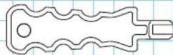
110-Style Punchdown Tool (Provided)
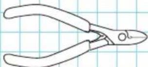
natural_image
Line drawing of a pair of pliers on grid paper (no text or symbols)Wire Cutter
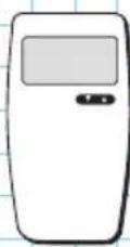
RJ-45 Tester
Follow these instructions to terminate the connector:
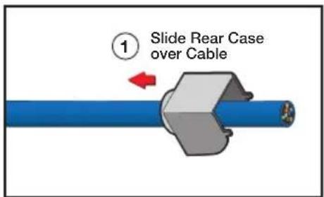
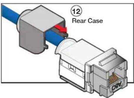
- Slide the rear case of the connector over the cable. Push the case back at least 3 inches (76 mm) to make room for the termination of the cable.
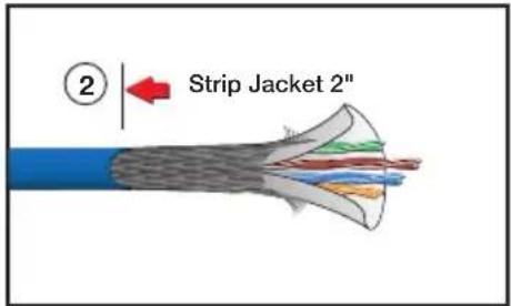
- Remove about 2 inches (50 mm) of the cable jacket.
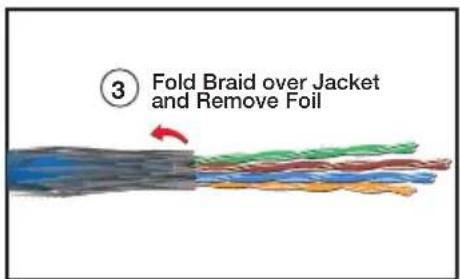
- Fold down the braid over the cable jacket. Remove the foil and mylar shielding (if present).
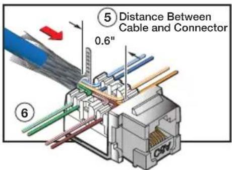
- Note the color codes and pin numbers on the sides of the connector. Follow the color code in the table at right to wire the connector.
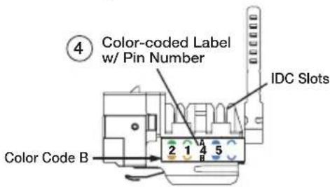
- Untwist the wire pairs and hold the end of the stripped cable jacket close to the back of the connector. The length of the exposed wires in the connector should not exceed 0.6 inch (see image at right).
ATTENTION: Failure to position the cable properly may result in crosstalk and improper termination.
| T568B WiringIDC Numbers & Color Codes | |
| IDC Position | T568B Wire Colors |
| 1 | White/Orange |
| 2 | Orange |
| 3 | White/Green |
| 4 | Blue |
| 5 | White/Blue |
| 6 | Green |
| 7 | White/Brown |
| 8 | Brown |
-
Position each wire into its respective IDC slot. Insert the wires just far enough to hold them in the IDC slots.
-
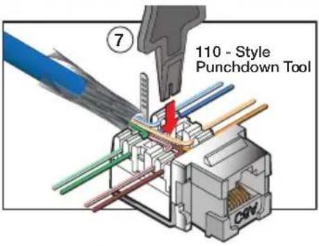
Use the 110-style punchdown tool to push down each wire into the IDC slot. Push the punchdown tool until the wire is firmly secured at the bottom of the slot.
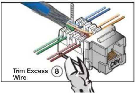
- Trim the excess wire flush with the body of the connector.
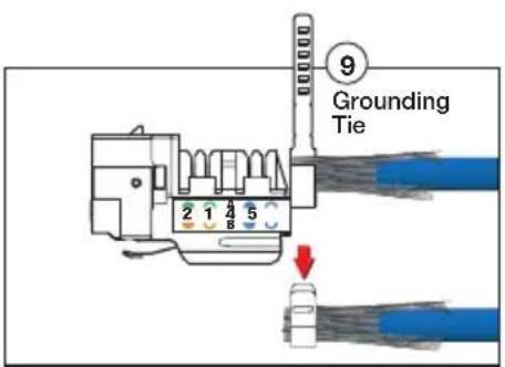
- Tighten the grounding tie around the braid.
- Remove the excess braid at the grounding tie.
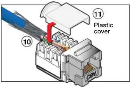
- Place the plastic cover over the termination wires for secure connection and added strain relief.
- Push the rear case forward until it clicks into position over the terminated connector.
- Test both ends of the cable for conductivity.
NOTE: If there is a need to re-terminate the connector, insert a tweeker on the bottom of the rear case and slide it back to access the wires.
NOTE: The wire retention mechanism in these connectors is very secure. If a terminated cable must be separated from its connector, separate it one wire at a time.
68-2370-50
Rev. C
04 13
Brand : Extron
Model : XTP DTP 24 Punch Down Jack
Category : Cables for Computers and Peripherals