Contour 1 - Uncategorized Joranalogue - Free user manual and instructions
Find the device manual for free Contour 1 Joranalogue in PDF.


| Product Type | Eurorack Synthesizer Module |
| Brand | Joranalogue |
| Model | Contour 1 |
| Module Width | 8 HP |
| Module Depth | 35 mm |
| Weight | 120 g |
| Power Supply | +12V / -12V, 45 mA each rail |
| Power Connector | 10-pin Eurorack header |
| Main Functions | Envelope generator, function generator, LFO, slew limiter |
| Controls | Rise, Fall, Shape, Level pots; CV inputs for rise/fall/level |
| Outputs | EOC, EOR gate outputs; bipolar signal output |
| CV Inputs | Rise, Fall, Level, Shape (0-5V or 0-10V) |
| Input Impedance | 100 kΩ |
| Output Impedance | 1 kΩ |
| Maximum Output Level | +/-10V |
| Frequency Range | 0.1 Hz to 10 kHz (approximate) |
| Maintenance and Cleaning | Wipe with a dry, lint-free cloth. Avoid solvents. |
| Safety | Do not expose to liquids or extreme temperatures. Connect only to Eurorack case. |
| Spare Parts and Repairability | Contact Joranalogue or authorized dealer for repairs. |
| General Information | Analog design, skiff-friendly, reverse power protection. |
Frequently Asked Questions - Contour 1 Joranalogue
User questions about Contour 1 Joranalogue
0 question about this device. Answer the ones you know or ask your own.
Ask a new question about this device
Download the instructions for your Uncategorized in PDF format for free! Find your manual Contour 1 - Joranalogue and take your electronic device back in hand. On this page are published all the documents necessary for the use of your device. Contour 1 by Joranalogue.
USER MANUAL Contour 1 Joranalogue
For decades, the voltage controlled slew limiter has been a staple of modular synthesisers. With its extreme versatility, it can be used to slew control voltages (CVs), create envelopes, as a low-frequency or audio oscillator and much more.
Today, Contour 1 brings a fresh approach to this classic circuit. It delivers much improved performance and control by incorporating modern design techniques.
At its most basic, a slew limiter slows down the rate of voltage change in a signal. On Contour 1, the rising and falling rates can be individually set using sliders and CV modulation.
The gate and trigger inputs allow the module to be used as a function generator: create snappy attack-release (AR) and attack-decay (AD) envelopes, with slope times ranging from 500 s to 30 seconds. The dedicated gate input makes it easy to generate +10 V envelopes from any signal source. Using the large tactile push button, AD envelopes can be manually triggered. A trigger will also reset the output voltage.
When set to loop mode, Contour1 will continually re-trigger itself. In this mode, it fulfils the role of a variable-shape low-frequency oscillator (LFO) or temperature-stable voltage controlled oscillator (VCO) in the audio range.
Both the rising and falling slopes can be individually bent, from concave through linear to convex. While doing so, the deviation in slope time, and thus oscillation frequency, is kept to a minimum. Since the bend parameters are separately voltage controllable, boundless modulation possibilities present themselves.
Explore anything from shape-shifting envelopes to rich VCO timbres: Contour 1 will make you re-think what a slew limiter can do.
CONTENTS
In the Contour 1 box, you'll find:
■ Product card, stating serial number and production batch.
■ 16-to-10-pin Eurorack power cable.
- Mounting hardware: two black M3 x 6 mm hex screws, two black nylon washers and a hex key.
- The Contour 1 module itself, in a protective cotton bag.
If any of these items are missing, please contact your dealer or support@joranalogue.com.
CONTROLS & CONNECTIONS
1 SLEW RATE SLIDERS
Use these sliders to set the rising and falling slew rates, from fast on the bottom to slow on top. In the full mode, the 0 to +10 V slew time range is 500 s to 30 seconds (1 kHz to 8.3 mHz loop). In the audio mode, it is 500 s to 30 ms (1 kHz to 16 Hz loop).
The LEDs on the levers, show the module's status in real time. When the slew core is rising or falling, only the corresponding LED will light up. When it is holding, both LEDs will be illuminated. The brightness is at all times correlated with the positive output voltage.
2 TRIGGER BUTTON AND INPUT
Pressing the trigger button or applying a rising edge to the trigger input has two effects: firstly, it resets the output voltage to 0 V. Secondly, while in slew mode, it starts a single-shot: the voltage will rise to +10 V, and then fall again until it reaches the voltage on the analogue input. This feature can be used to create attack-decay (AD) envelopes.
Contour 1's trigger, gate and hold inputs are uniquely designed to be driven reliably even from weak, slow, bipolar signals. They feature Schmitt action, with a +2 V low and +3 V high logic threshold.
3 SLEW/LOOP SWITCH
With this switch to the left, Contour1 will function as a standard slew limiter or envelope generator. Set it to the right, and the circuit will continually re-trigger itself for sustained oscillation.
In this mode, the output voltage will rise to +10 V, and subsequently fall to the voltage at the analogue input. Once this point is reached, a new cycle will start. Adjust the rise and fall slew rates to change both the frequency and waveshape of the output signal.
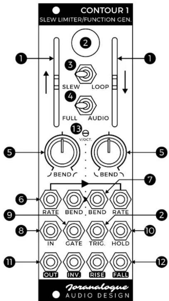
4 FREQUENCY RANGE SWITCH
This switch determines over which time range Contour1 will operate: full (slew limiter, VCLFO, envelope generator, envelope follower...) or audio frequency (VCO, VCF, waveshaper...).
5 BEND KNOBS
Using these knobs, the rising and falling slopes can be individually bent: from concave through linear to convex. While in loop mode, changing the shape will inevitably affect slope time as well. However, Contour1 has been designed to minimise this effect as much as possible.
6 SLEW RATE CV INPUTS
An increase in voltage at one of these CV inputs will increase the corresponding slew rate, and thus decrease the slew time.
The rise CV socket is normalised to the fall CV, allowing both to be modulated by the same source simultaneously. In this case, the module will respond at a standard 1 volt per octave. For the best possible pitch tracking performance, set both rise and fall slew rates equal and the slope shapes linear (bend knobs centred).
7 BEND CV INPUTS
These inputs are used to modulate the slope shapes. With the corresponding bend knob centred, the CV range is -5 V to +5 V. Both slopes can be modulated separately or together thanks to the normalisation from rise to fall.
8 ANALOGUE INPUT
Apply the signal to be slew limited to this input socket. When the gate, trigger or loop features are used, this sets the minimum voltage for each cycle (0 V by default).
9 GATE INPUT
The gate input has a different function depending on Contour 1's mode of operation.
In slew mode, a high gate switches the source between the analogue input socket and a precision +10 V reference. This allows accurate attack-release (AR) envelopes to be created from any gate signal.
In loop mode, it allows for gated oscillation: once a cable is inserted in the socket, Contour 1 will only loop while the incoming gate is high.
10 HOLD INPUT
A hold gate signal 'freezes' the slew core, slowing it down to near-standstill until the hold is released. This is useful for halting modulations, or as a sync-like effect at audio frequencies.
11 ANALOGUE OUTPUTS
The slew limited output signal is available from the main output socket. It is highly accurate and impedance-compensated, allowing portamento effects to be applied on pitch-accurate CV sequences. An inverted output is included as well.
12 SLOPE GATE OUTPUTS
These gate outputs go high (+5 V) whenever the slew core is rising or falling. At any other time, they are low (0 V).
13 VOLT PER OCTAVE TRIMMER
This trim potentiometer is used to calibrate the module's pitch tracking. Since it is accessible from the front panel, calibration can be easily performed without removing the module from the system. Each module is individually calibrated during production; do not adjust this trimmer if not needed.
Should you find your Contour 1 to be out of tune, set it to loop mode, range switch to audio, both slew rate sliders to about 30 % down from the top positions, and both bend knobs centred.
Make sure Contour1 has been powered for at least 20 minutes at a stable ambient temperature. Now connect any output to a calibrated digital tuner. The rise slew rate CV input should be switched between 0 V and a precision +4 V source, toggled automatically or by hand. Leave all other inputs unpatched.
Using a dedicated trimming tool or standard 2.5 mm flat screwdriver, adjust the trimmer until the interval between both states is exactly 4 octaves.
PATCH IDEAS
IMPROVED SAW WAVE OSCILLATOR
Approximate saw/ramp waves can be created by engaging loop mode, setting one of the slew directions to a rather slow rate and the other to the maximum rate. However, it is possible to speed up the saw 'step' immensely by taking advantage of the resetting trigger feature.
Simply patch the fall gate output to the trigger input. Now, as the module enters the fall period, rather than slewing down at the selected fall slew rate, the output voltage will instantly reset to 0 V, resulting in a brighter saw sound.
COMBINED FM/AM VCO
The lower voltage bound in loop mode is determined by the analogue input, a unique feature creating deep modulation possibilities.
With Contour1 patched as a VCO, apply an external oscillator's output to the signal input. This causes a combination of frequency and amplitude modulation, as the module will oscillate 'on top of the modulator signal.
Vary the input amplitude to adjust the modulation depth. This technique can of course be combined with rate and bend modulation, manual, external or via feedback, resulting in an extreme range of possible waveforms.
SUBHARMONIC GENERATOR
To create this classic patch using Contour1, process the signal source through a normally closed gated switch, the output of which is sent to the trigger input. The rise gate output drives the switch, disabling triggering during the rise stage.
The resulting waveforms at Contour 1's outputs will be at a subharmonic frequency of the original source. Vary the rise time to select different subharmonics.
ENVELOPE FOLLOWER
To extract an envelope from a signal applied to the analogue input, set the rise slew rate to the fastest and the fall to a moderate setting, in the full rate range and slew mode. Varying the fall rate results in different decay settings. The output signal can be used to modulate any aspect elsewhere in the patch, for example a lowpass filter.
You can also increase the rise rate to reject transients. A concave fall bend will create the most 'natural' sounding decay.
VOLTAGE CONTROLLED FILTER
Fast signal edges represent high frequency harmonic content. Slewing a signal attenuates these harmonics. In other words, a slew limiter can function as a type of lowpass filter. The (by default) linear slopes and separate rise/fall slewing differentiate the sound from a standard lowpass filter.
Set both slew rates to the maximum speed, in audio range slew mode, and apply an audio signal to the analogue input. Use a signal containing fast edges, such as a square wave, for best effect.
Lowering both the slew rates results in a filtering effect on the analogue output. The rise/fall gate outputs deliver bonus pulse signals.
PULSE WIDTH MODIFIER/DELAY
Shrinking, stretching and delaying pulses has a multitude of uses within a modular system. These pulses can be gates, triggers or audio frequency signals.
With the module set in slew mode, patch the pulse source to the trigger input. Two pulses are generated on a trigger: one on the rise output, and another on the fall. The width of each pulse is controlled by the corresponding slew rate. The fall pulse is delayed, with the delay time set by the rise rate.
SPECIFICATIONS
Module format
Doepfer A-100 'Eurorack' compatible module
3 U, 8 HP, 30 mm deep (inc. power cable)
Milled 2 mm aluminium front panel with non-erasable graphics
Maximum current draw
+12 V: 90 mA
-12 V: 85 mA
Power protection
Reverse polarity (MOSFET)
I/O impedance
All inputs: 100 kΩ
Analogue outputs: 0 Ω (impedance comp.)
Gate outputs: 1 kΩ
Outer dimensions (H x W x D)
128.5 x 40.3 x 43 mm
Mass
Module: 110 g
Including packaging and accessories: 195 g
SUPPORT
As all Joranalogue Audio Design products,
Contour 1 is designed, manufactured and tested with the highest standards, to provide the performance and reliability music professionals expect.
In case your module isn't functioning as it should, make sure to check your Eurorack power supply and all connections first.
If the problem persists, contact your dealer or send an email to support@joranalogue.com.
Please mention your serial number, which can be found on the product card or on the module's rear side.
REVISION HISTORY
Revision D: no functional changes.
Revision C: initial release.
With compliments to the following fine people, who helped to make Contour 1 a reality!
Ben 'DivKid' Wilson Björn Jauss
Boris Uytterhaegen Gregory Delabelle
Jan D'Hooghe Jens Van Daele
Everyone at Wired Electronics
Contour 1 User Manual
version 2019-09-18
21 ^st Century Analogue Synthesis—Made in Belgium
© 2019
Joranalogue
AUDIO DESIGN
info@joranalogue.com
https://joranalogue.com/

- CONTENTS
- CONTROLS & CONNECTIONS
- SLEW RATE SLIDERS
- TRIGGER BUTTON AND INPUT
- SLEW/LOOP SWITCH
- FREQUENCY RANGE SWITCH
- BEND KNOBS
- SLEW RATE CV INPUTS
- BEND CV INPUTS
- ANALOGUE INPUT
- GATE INPUT
- HOLD INPUT
- ANALOGUE OUTPUTS
- SLOPE GATE OUTPUTS
- VOLT PER OCTAVE TRIMMER
- PATCH IDEAS
- IMPROVED SAW WAVE OSCILLATOR
- COMBINED FM/AM VCO
- SUBHARMONIC GENERATOR
- ENVELOPE FOLLOWER
- VOLTAGE CONTROLLED FILTER
- PULSE WIDTH MODIFIER/DELAY
- SPECIFICATIONS
- SUPPORT
- REVISION HISTORY
Brand : Joranalogue
Model : Contour 1
Category : Uncategorized