Switch 4 - Synthesizer Joranalogue - Free user manual and instructions
Find the device manual for free Switch 4 Joranalogue in PDF.

User questions about Switch 4 Joranalogue
0 question about this device. Answer the ones you know or ask your own.
Ask a new question about this device
Download the instructions for your Synthesizer in PDF format for free! Find your manual Switch 4 - Joranalogue and take your electronic device back in hand. On this page are published all the documents necessary for the use of your device. Switch 4 by Joranalogue.
USER MANUAL Switch 4 Joranalogue
Designed with and for performing artists, Switch 4 delivers a hands-on signal switching and routing solution for your Eurorack modular synthesiser.
Quickly mute audio signals, trigger envelopes live, select modulation sources on the fly... With custom dual-action toggle switches, an intuitive interface and sturdy construction. Switch 4 will prove just as useful on stage as in the studio.
The bottom switching section includes four lever-actuated toggle switches, to make or break the signal path between the inputs and outputs. These switches feature a dual action: latched upwards, momentary downwards.
The four input signals are also sent to the top routing section, where two rotary switches allow you to select the signals to be sent to the matching outputs. Here you'll also find dual-action toggle switches, for added versatility.
Finally, all signal paths are buffered, avoiding signal cuts when shorting a jack during patching or severe loading effects when driving many inputs. The high-end components provide exceptionally low noise and distortion, so Switch 4 can reliably process audio, control voltages and gates/triggers.
CONTENTS
In the Switch 4 box, you'll find:
■ Product card, stating serial number and production batch.
■ 16-to-10-pin Eurorack power cable.
- Mounting hardware: two black M3 x 6 mm hex screws, two black nylon washers and a hex key.
- The Switch 4 module itself, in a protective cotton bag.
If any of these items are missing, please contact your dealer or support@joranalogue.com.
CONTROLS & CONNECTIONS
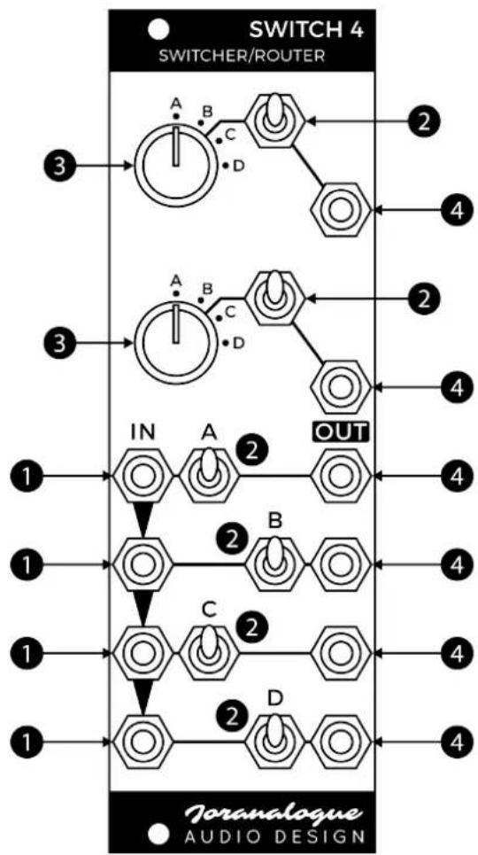
1 SIGNAL INPUTS
The four inputs are arranged in a column. The sockets are normalised top to bottom, so a single signal can be sent to multiple destinations. For example, if only the A socket is used, the signal will also be sent to the B, C and D inputs. Any kind of signal can be used: audio, CV or gate/trigger.
Input socket A includes a +5 V normalisation. Simply leave the socket unused to easily create manual gates.
2 TOGGLE SWITCHES
Switch 4 contains six dual-action toggle switches: one for each output. The corresponding signal is sent to the output socket if the switch is in the upper (latched) or lower (momentary) position, while the connection is interrupted if the switch is in the centre position. This dual switching action gives tremendous control during live performances.
3 ROTARY SWITCHES
The top routing section contains two rotary switches, which can each be set to select one of the four inputs. The selected signal is then sent to the toggle switch right next to the rotary switch. When that switch is active, the selected input signal will be available at the output.
4 SIGNAL OUTPUTS
The switched and routed signals are available at the output sockets. These are impedance-compensated, allowing pitch CVs to be switched while retaining their accuracy.
flowchart
graph TD
    subgraph SWITCH 4
        direction TB
        A1["Power Supply"] -->|A| Switch1["Switch"]
        A2["Power Supply"] -->|B| Switch2["Switch"]
        A3["Power Supply"] -->|C| Switch3["Switch"]
        A4["Power Supply"] -->|D| Switch4["Switch"]
    end
    subgraph OUTPUT
        direction TB
        IN1["IN"] -->|1| A1
        IN2["IN"] -->|2| A2
        OUT1["OUT"] -->|2| A3
        OUT2["OUT"] -->|2| A4
        OUT3["OUT"] -->|2| A5
        OUT4["OUT"] -->|2| A6
        OUT5["OUT"] -->|2| A7
        OUT6["OUT"] -->|2| A8
        OUT7["OUT"] -->|2| A9
        OUT8["OUT"] -->|2| A10
        OUT9["OUT"] -->|2| A11
        OUT10["OUT"] -->|2| A12
    end
    style SWITCH 4 fill:#f9f,stroke:#333
    style OUTPUT fill:#ccf,stroke:#333
PATCH IDEAS
DUAL MODULATION SELECTOR
Connect four CV sources (LFOs, envelopes, sequences...) to the inputs, and the two routing outputs to CV inputs you want to modulate on other modules. Now you can very quickly select between modulation sources, just by turning the rotary switches. Enable or disable modulation using the routing section's toggle switches.
EFFECTS CONTROLLER
Send an audio signal to the A input, and connect the outputs to various signal processors: filters, wavefolders, delays... Mix the resulting signals together with a mixing module. This way, the module's toggle switches control different effects on the original signal.
SPECIFICATIONS
FORMAT
Doepfer A-100 'Eurorack' compatible module
3 U, 8 HP, 30 mm deep (inc. power cable)
Milled 2 mm aluminium front panel with non-erasable graphics
MAXIMUM CURRENT DRAW
+12 V: 25 mA
-12 V: 25 mA
POWER PROTECTION
Reverse polarity (MOSFET)
I/O IMPEDANCE
All inputs: 100 kΩ
All outputs: 0 Ω (compensated)
TOTAL HARMONIC DISTORTION
0.0001 % maximum (1 kHz, 64 harmonics)
NOISE
-100 dBu maximum
OUTER DIMENSIONS
128.5 x 40.3 x 43 mm (H x W x D)
MASS
Module: 100 g
Including packaging & accessories: 185 g
SUPPORT
As all Joranalogue Audio Design products, Switch 4 is designed, manufactured and tested with the highest standards, to provide the performance and reliability music professionals expect.
In case your module isn't functioning as it should, make sure to check your Eurorack power supply and all connections first.
If the problem persists, contact your dealer or send an email to support@joranalogue.com. Please mention your serial number, which can be found on the product card or on the module's rear side.
REVISION HISTORY
Revision D: eliminated the possibility of glitches appearing on the routing outputs while turning the corresponding rotary switches.
Revision C: added +5 V normalisation on input A and output impedance compensation. Current draw is increased from ±10 mA to ±25 mA.
Revision B: initial release.
With compliments to the following fine people, who helped to make Switch 4 a reality!
Björn Jauss Boris Uytterhaegen
Gregory Delabelle Jan D'Hooghe
Jens Van Daele Vincent Vanesse
Everyone at Wired Electronics
Switch 4 User Manual version 2019-06-06
21 ^st Century Analogue Synthesis—Made in Belgium
© 2019
Joranologue AUDIO DESIGN
info@joranalogue.com https://joranalogue.com/