Compare 2 - Synthesizer Joranalogue - Free user manual and instructions
Find the device manual for free Compare 2 Joranalogue in PDF.

User questions about Compare 2 Joranalogue
0 question about this device. Answer the ones you know or ask your own.
Ask a new question about this device
Download the instructions for your Synthesizer in PDF format for free! Find your manual Compare 2 - Joranalogue and take your electronic device back in hand. On this page are published all the documents necessary for the use of your device. Compare 2 by Joranalogue.
USER MANUAL Compare 2 Joranalogue
The window comparator is a very useful circuit building block that is common in general electronics, but rarely found in modular synths. While a regular comparator activates when the input signal voltage is higher than a threshold level, a window comparator checks if the voltage is between two levels (these form the 'window').
Compare 2 combines two such comparators and a logic section in 8 HP. The result is an advanced tool for extracting gates and pulses from analogue signals in Eurorack synths.
The detection windows are defined by the shift and size parameters, which can be varied using the knobs and control voltage (CV) inputs. Complementary gate outputs are available, with big three-colour LEDs showing each comparator's status in real-time.
All inputs are normalised from the left section to the right, but the two comparators can also be used completely independently. On the bottom, the gates from both comparators are combined in various ways by the logic section, which also features LEDs.
You'll find a use for this truly multi-functional module in practically any patch, processing either CV or audio: complex rhythm generator, dual pulse width modulator, frequency multiplier/divider with PWM, digital 'ring modulator' with PWM, dynamic depth VCO synchronizer, voltage controlled swing, logic function array with adjustable thresholds... and many more applications waiting to be discovered!
CONTENTS
In the Compare 2 box, you'll find:
- Product card, stating serial number and production batch.
■ 16-to-10-pin Eurorack power cable. - Mounting hardware: two black M3 x 6 mm hex screws, two black nylon washers and a hex key.
- The Compare 2 module itself, in a protective cotton bag.
If any of these items are missing, please contact your dealer or support@joranalogue.com.
CONTROLS & CONNECTIONS
1 SHIFT KNOBS
Each of the identical window comparators features a knob to offset the window's centre. The range is -5 V to +5 V, with 0 V in the centre position.
2 SIZE KNOBS
Each comparator also includes a size knob, which controls the distance between the window edges, from very small (a few mV) to 10 V maximum.
3 SHIFT AND SIZE CV INPUTS
The windows can be independently modulated using these CV inputs. The modulation voltages are then added to the knob settings to generate the final detection windows.
The CVs of the left comparator are normalised to the right, so both comparators can be voltage controlled together.
Note that both CV inputs can process negative control voltages as well. In the case of the size parameter, this can cause the window to become negative, which simply means the comparator output will never become active.
4 SIGNAL INPUTS
Connect the analogue signals you want to extract gates and pulses from to these sockets. Both CV and audio can be processed. These sockets are also normalised left to right, so by default the same signal is sent to both comparators.
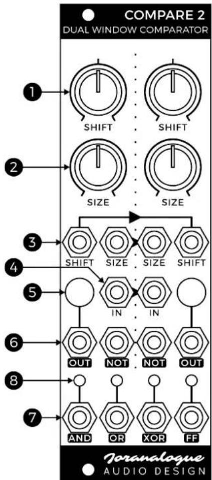
text_image
COMPARE 2 DUAL WINDOW COMPARATOR 1 SHIFT SHIFT 2 SIZE SIZE 3 SHIFT SIZE SIZE SHIFT 4 IN IN 5 OUT NOT NOT OUT 6 AND OR XOR FF 7 Joranalogue AUDIO DESIGN5 COMPARATOR LEDS
Compare 2's most striking feature are the two multi-colour LEDs, which visualise the status of each comparator. They light up blue when the input voltage is below the window, red when above and white when inside.
If the window size is negative, and the signal is within this 'negative window', the LED will turn off rather than turn white.
6 GATE OUTPUTS
When a comparator detects the input signal inside the window, the corresponding main gate output, labelled 'OUT', will be active (+5 V). Otherwise, it is inactive (0 V).
The NOT output is logically inverted, so it is active whenever the main output is inactive and vice versa.
7 LOGIC SECTION OUTPUTS
The outputs from both comparators are sent to the logic section, where additional signals are derived. AND will be active only when both comparators are active, OR when one or both are active and XOR only when one is active. Rising edges of the XOR signal also toggle a flip-flop ('FF'). All these outputs are +5 V active, 0 V inactive.
8 LOGIC SECTION LEDS
Each logic output has a corresponding LED which lights up whenever it is active.
PATCH IDEAS
COMPLEX RHYTHM GENERATOR
Patch a LFO signal to the left comparator input. Now, different gate signals will be generated on the logic outputs at different points in the LFO cycle, depending on the knob settings. These can be used to trigger envelopes, drum modules, sequencers etc. Change the rhythms by turning the parameter knobs or using the CV inputs.
DUAL PULSE WIDTH MODULATOR
Compare 2 can also be used at audio frequencies. Connect an analogue waveform from a VCO (preferably triangle) to a comparator's input. Connect the gate output to a mixer, line output module etc. so you can hear it. A pulse waveform is generated, controlled by the shift and size parameters. Unlike a regular pulse, the frequency can transition between fundamental and +1 octave. Phase modulation is also possible, by modulating the shift parameter with a narrow window size. Each comparator can function as an independent pulse width modulator.
FREQUENCY MULTIPLIER/DIVIDER
This patch idea is similar to the dual pulse width modulator, except the same signal is sent to both comparators and the XOR output is used. Depending on the window parameters, the output signal's frequency can now transition between fundamental, +1 and +2 octave shift, with various complex pulse waveforms. Use the FF output for -1/0/+1 octave shift.
DIGITAL RING MODULATOR
By connecting signals with two different frequencies to both comparator signal inputs and using the XOR as an audio output, digital ring modulation-type sounds can be generated. The knobs and CV inputs allow these sounds to be pulse width-modulated.
DYNAMIC DEPTH OSCILLATOR SYNC
Using Compare 2, any VCO can be given soft-synchronization capability with dynamic depth. Connect one of the to-be sync'ed VCO's outputs to input 1, and the sync source signal (usually another VCO) to input 2. Now patch the XOR output to the VCO's FM input. This input should have a dedicated modulation depth knob.
Listen to one of the VCO's outputs. The sync timbre will depend on the frequencies of the VCO and sync source, the FM depth and Compare 2 parameters. Send the FM signal through a VCA for voltage control over the sync depth.
CHAOTIC ENVELOPE LOOPER
Allow a standard envelope generator to loop using Compare 2: patch the envelope output to the left comparator input, and the flip-flop output back to the EG's gate input. The envelope will now oscillate between two boundary levels, as determined by Compare 2's windows. Modulating any window parameter(s) with a LFO quickly results in a chaotic patch.
LOGIC FUNCTION ARRAY
If you just need logic functions to combine gate signals in a particular patch, Compare 2 can be used for that as well. In this case, you'll want to ensure the comparators are inactive when the input signal is 0, and active when it is +5 V. Set the shift knob to maximum and size to the centre position. The window's edges will now be set at +2.5 V and +7.5 V, reliably activating the comparator on gate signals as long as they do not exceed +7.5 V. Now just patch the outputs as needed.
The shift and size CV inputs can function as additional gate inputs, giving AND or OR functions in combination with the signal input, depending on the window settings. This means a total of 6 gate input signals can be processed for complex logic functions.
SPECIFICATIONS
MODULE FORMAT
Doepfer A-100 'Eurorack' compatible module 3 U, 8 HP, 30 mm deep (inc. power cable)
Milled 2 mm aluminium front panel with non-erasable graphics
MAXIMUM CURRENT DRAW
+12 V: 20 mA
-12 V: 15 mA
POWER PROTECTION
Reverse polarity (MOSFET)
I/O IMPEDANCE
All inputs: 100 kΩ
All outputs: 1 kΩ
OUTER DIMENSIONS (H X W X D)
128.5 x 40.3 x 43 mm
MASS
Module: 95 g
Including packaging and accessories: 180 g
SUPPORT
As all Joranalogue Audio Design products, Compare 2 is designed, manufactured and tested with the highest standards, to provide the performance and reliability music professionals expect.
In case your module isn't functioning as it should, make sure to check your Eurorack power supply and all connections first.
If the problem persists, contact your dealer or send an email to support@joranalogue.com. Please mention your serial number, which can be found on the product card or on the module's rear side.
REVISION HISTORY
Revision C: initial release.
With compliments to the following fine people, who helped to make Compare 2 a reality!
Björn Jauss Boris Uytterhaegen
Gregory Delabelle Jan D'Hooghe
Jean Rochet Jens Van Daele
Lieven Stockx Olivier Carlier
Everyone at Wired Electronics
Compare 2 User Manual version 2018-06-18
© 2018
Joranalogue
AUDIO DESIGN
info@joranalogue.com
https://joranalogue.com/
Designed & made in Belgium