
Select 2 - Uncategorized Joranalogue - Free user manual and instructions
Find the device manual for free Select 2 Joranalogue in PDF.


| Product Type | Dual CV Processor (Eurorack Module) |
| Brand | Joranalogue |
| Model | Select 2 |
| Module Format | Doepfer A-100 Eurorack compatible, 3U, 6 HP, 30 mm depth (incl. power cable) |
| Front Panel | Milled 2 mm aluminum with non-erasable graphics |
| Dimensions (H x W x D) | 128.5 x 30 x 43 mm (module only) |
| Weight | Module: 80 g; with packaging: 165 g |
| Power Requirements | +12 V: 25 mA, -12 V: 25 mA |
| Power Protection | Reverse polarity (MOSFET) |
| Input Impedance | All inputs: 100 kΩ |
| Output Impedance | All outputs: 0 Ω (compensated) |
| DC Voltage Error | 0.3 % maximum |
| Bandwidth | 25 kHz (-1 dB) |
| Main Functions | Dual voltage-controlled signal processor: create, switch, mute, hold, invert, attenuate, offset, add/mix, and subtract voltages (CV to audio) |
| Key Features | Two signal inputs per channel (normalized to +5V and 0V), gate-controlled selector, track-and-hold with low droop (minutes), gated polariser/attenuverter with unity gate input, automatic mixing of A and B outputs when A unused |
| Controls | Two polariser knobs, gate inputs (select, hold, unity), dual-color output LEDs |
| Gate Input Logic | Schmitt trigger: low threshold +2 V, high threshold +3 V; accepts weak/bipolar signals |
| Output LED Indication | Blue for negative voltage, red for positive voltage |
| Included Accessories | Product card, 16-to-10 pin Eurorack power cable, mounting hardware (2x M3 screws, 2x nylon washers, hex key), protective cotton bag |
| Compliance & Safety | Designed, manufactured, and tested for professional performance and reliability |
| Maintenance | No specific maintenance required; keep dry and clean; avoid exposure to liquids or extreme temperatures |
| Repairability / Spare Parts | Contact dealer or support@joranalogue.com; mention serial number (found on product card or module rear) |
| Country of Manufacture | Belgium |
Frequently Asked Questions - Select 2 Joranalogue
User questions about Select 2 Joranalogue
0 question about this device. Answer the ones you know or ask your own.
Ask a new question about this device
Download the instructions for your Uncategorized in PDF format for free! Find your manual Select 2 - Joranalogue and take your electronic device back in hand. On this page are published all the documents necessary for the use of your device. Select 2 by Joranalogue.
USER MANUAL Select 2 Joranalogue
A 'Swiss Army knife' for your modular system. Select 2 provides two highly accurate gate-controlled voltage processors in 6 HP. These allow you to create, switch, mute, hold, invert, attenuate, offset, add/mix and subtract voltages, from slow control voltages (CVs) up to audio frequencies.
Each processor features two signal inputs, with the left input used by default. A gate on the 'select' input switches to the right signal input instead. The signal inputs are normalised to the precision +5 V reference (left) and 0 V (right).
Following the input section is a hold circuit. A rising edge on the 'hold' input freezes the input voltage at that moment, until the gate input goes low again. While most sample/track-and-hold modules only manage a few seconds, Select 2's 'low droop' design enables it to store a held voltage accurately for several minutes.
The end of the signal path consists of a gated polariser/attenuverter. Using the knob, the voltage at the output can attenuated and/or inverted: the gain is -1 (inverted) at the minimum setting, 0 at the centre and +1 (unity gain) at the maximum. The polariser can be disabled using the 'unity' gate input. This unique ability enables a variety of interesting gate-controlled signal modulations. Dual-colour LEDs show the output voltage of each processor.
Finally, if the A output socket is left unused, the signal is mixed together with the B output. This enables signal offsetting, CV mixing, pitch transposing etc.
CONTENTS
In the Select 2 box, you'll find:
- Product card, stating serial number and production batch.
■ 16-to-10-pin Eurorack power cable. - Mounting hardware: two black M3 x 6 mm hex screws, two black nylon washers and a hex key.
- The Select 2 module itself, in a protective cotton bag.
If any of these items are missing, please contact your dealer or support@joranalogue.com.
CONTROLS & CONNECTIONS
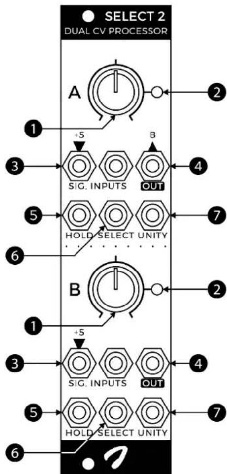
1 POLARISER KNOBS
Each of the identical voltage processors features a knob to control the polariser. The signal is inverted at the minimum setting, fully attenuated (0 V) at the centre and remains unity gain at maximum.
2 OUTPUT LEDS
These bi-colour LEDs visualise the processor output voltages in real time: blue for negative, red for positive.
3 SIGNAL INPUTS
There are two analogue signal inputs for each processor, with the left input being used by default. For constant voltage generation, simply leave all input sockets unused: the left signal input is normalised to +5 V.
4 OUTPUTS
Each processor has an accurate, impedance-compensated signal output.
If nothing is plugged into the A output socket, its output signal is mixed together with the B output. This allows you to apply an offset to a signal, mix two signals etc.
5 HOLD GATE INPUTS
Apply a gate signal to the hold input to 'freeze' the input voltage. While the hold gate is high, any changes on the signal inputs are ignored. When gate goes low again, the circuit snaps back to the voltage at the currently selected input.
Each processor can thus function as a track-and-hold for both CV and audio. However, the exceptionally low leakage rate also allows minutes-long storage of pitch-accurate CVs.
All of Select 2's gate inputs are uniquely designed to be driven reliably even from weak, slow, bipolar signals. They feature Schmitt action, with a +2 V low and +3 V high logic threshold.
flowchart
graph TD
    A["Select 2<br>DUAL CV PROCESSOR"] --> B["1: +5"]
    B --> C["SIG. INPUTS"]
    B --> D["OUT"]
    D --> E["3"]
    E --> F["5"]
    F --> G["HOLD SELECT UNITY"]
    G --> H["6"]
    H --> I["7"]
    I --> J["2"]
    J --> K["2"]
    K --> L["1: +5"]
    L --> M["SIG. INPUTS"]
    L --> N["OUT"]
    N --> O["4"]
    O --> P["5"]
    P --> Q["HOLD SELECT UNITY"]
    Q --> R["7"]
    R --> S["6"]
6 SELECT GATE INPUTS
This gate input selects between the processor's signal inputs: if unused or low, the left signal input is selected. A high gate signal selects the right input instead.
Apart from selecting between two inputs, this gated selector switch also allows you to create gate-activated constant voltages or to mute signals.
7 UNITY GATE INPUTS
The unity gate input is used to disable the polariser. When disabled, the output signal simply remains at unity gain, as if the polariser knob would be set to the maximum position.
PATCH IDEAS
GATED CONSTANT VOLTAGE GENERATOR
If none of a processor's signal or gate inputs are used, the +5 V reference voltage is sent to the polariser. Use the knob to generate a manually variable voltage between -5 V and +5 V at the polariser's output. This is useful for controlling CV inputs without dedicated knobs.
This constant voltage can be disabled (switched to 0 V) using the select gate input. When the select gate is active, the right signal input is selected, which is 0 V by default. The output signal can also be switched to +5 V using the unity gate input, which disables the polariser.
GATED ATTENUATOR/POLARISER AND MUTER
Similar to the gated constant voltage generator, except in this application an external signal is connected to the left signal input. Now the knob attenuates and polarizes the signal. Mute it with a select gate, and disable the polariser using the unity gate input.
RING MODULATOR
Select 2 can be used to create classic ring modulator tones. Set the knob to the minimum setting and connect your audio-rate carrier and modulator signals to the left signal and unity gate inputs respectively. The modulator should be a square or pulse wave for the best result, as this is a logic input. Use the knob to control the depth of the ring modulator effect.
AUDIO TRACK-AND-HOLD
Another classic synthesiser audio effect is the track-and-hold, creating digital-sounding 'downsample' tones using analogue circuitry. Patch Select 2 like the ring modulator, except the modulator is sent to the hold input. While the hold input is high, the carrier signal is 'frozen'. Once the hold goes low again, the output snaps to follow the carrier input. Vary the pulsewidth of the modulator to sweep from a subtle effect to full-on sample-and-hold.
VARIABLE WAVEMORPHER
Connect two different waveshapes from an oscillator (for example, sine and saw) to the two signal inputs, and the oscillator's pulse output to the select gate input. The result is a morphed signal, where each waveshape makes up part of the total period. By adjusting the oscillator's pulsewidth parameter, the morphing can be varied.
SEQUENCE SELECTOR
Patch two CV sequences to both signal inputs, and a gate sequence to the select gate input, all driven from the same clock. Now the gate sequence selects between both CV sequences: left when low, right when high. Easily create new hybrid melodies just by changing the gate sequence.
ATTENUATOR/POLARIZER AND OFFSET
Thanks to the mixing feature, both sections can be used together to both attenuate/polarise and offset a signal. Simply plug your signal into the left B input. The A knob controls the -5 V to +5 V offset, while the B knob controls the attenuation and polarisation.
This method also allows -10 V to +10 V constant voltages to be generated from the bottom processor, when all inputs are unused.
GATE-TO-AUDIO CONVERTER
If you have an audio-rate gate signal (switching between 0 V and +5 V), you can convert it to a standard zero-centred 10 V_pp (-5 to +5 V) signal using Select 2. Set one of the knobs to the minimum setting, plug your signal into the corresponding unity gate input, and leave all other inputs on that section unused. The output signal is a 10 V_pp square wave, not inverted with respect to the original gate signal.
SPECIFICATIONS
MODULE FORMAT
Doepfer A-100 'Eurorack' compatible module
3 U, 6 HP, 30 mm deep (inc. power cable)
Milled 2 mm aluminium front panel with non-erasable graphics
MAXIMUM CURRENT DRAW
+12 V: 25 mA
-12 V: 25 mA
POWER PROTECTION
Reverse polarity (MOSFET)
I/O IMPEDANCE
All inputs: 100 kΩ
All outputs: 0 Ω (compensated)
DC VOLTAGE ERROR
0.3 % maximum
BANDWIDTH
25 kHz (-1 dB)
OUTER DIMENSIONS
128.5 x 30 x 43 mm (H x W x D)
MASS
Module: 80 g
Including packaging and accessories: 165 g
SUPPORT
As all Joranalogue Audio Design products, Select 2 is designed, manufactured and tested with the highest standards, to provide the performance and reliability music professionals expect.
In case your module isn't functioning as it should, make sure to check your Eurorack power supply and all connections first.
If the problem persists, contact your dealer or send an email to support@joranalogue.com. Please mention your serial number, which can be found on the product card or on the module's rear side.
REVISION HISTORY
Revision E: no functional changes.
Revision D: initial release.
With compliments to the following fine people, who helped to make Select 2 a reality!
Ben 'DivKid' Wilson Björn Jauss
Boris Uytterhaegen Gregory Delabelle
Jan D'Hooghe Jens Van Daele
Everyone at Wired Electronics
Select 2 User Manual version 2019-07-15
21 ^st Century Analogue Synthesis—Made in Belgium
© 2018–2019
Joranologue AUDIO DESIGN
info@joranalogue.com https://joranalogue.com/
- CONTENTS
- CONTROLS & CONNECTIONS
- POLARISER KNOBS
- OUTPUT LEDS
- SIGNAL INPUTS
- OUTPUTS
- HOLD GATE INPUTS
- SELECT GATE INPUTS
- UNITY GATE INPUTS
- PATCH IDEAS
- GATED CONSTANT VOLTAGE GENERATOR
- GATED ATTENUATOR/POLARISER AND MUTER
- RING MODULATOR
- AUDIO TRACK-AND-HOLD
- VARIABLE WAVEMORPHER
- SEQUENCE SELECTOR
- ATTENUATOR/POLARIZER AND OFFSET
- GATE-TO-AUDIO CONVERTER
- SPECIFICATIONS
- MODULE FORMAT
- MAXIMUM CURRENT DRAW
- POWER PROTECTION
- I/O IMPEDANCE
- DC VOLTAGE ERROR
- BANDWIDTH
- OUTER DIMENSIONS
- MASS
- SUPPORT
- REVISION HISTORY
Brand : Joranalogue
Model : Select 2
Category : Uncategorized