
JN3200 - Jigsaw MAKITA - Free user manual and instructions
Find the device manual for free JN3200 MAKITA in PDF.

| Product type | Jigsaw (nibbler) |
| Brand | MAKITA |
| Model | JN3200 |
| Max. cutting capacity - Mild steel | 3.2 mm (10 ga) |
| Max. cutting capacity - Stainless steel | 2.5 mm (13 ga) |
| Max. cutting capacity - Aluminium | 3.5 mm (10 ga) |
| Min. cutting radius - Outer edge | 128 mm |
| Min. cutting radius - Inner edge | 120 mm |
| Number of strokes per minute | 1 300 |
| Total length | 215 mm |
| Net weight | 3.4 kg |
| Power supply | Mains (power cord) |
| Rated voltage | 230 V (typical) |
| Protection class | Double insulation (Class II) |
| Recommended lubrication | Machine oil on cutting line |
| Cut materials | Mild steel, stainless steel, aluminium |
| Carbon brush replacement | When worn down to the limit line |
| Warranty | 1 year (limited) |
| Included in box | Punch, die, hex key, wrench 50, adjusting washer |
Frequently Asked Questions - JN3200 MAKITA
User questions about JN3200 MAKITA
0 question about this device. Answer the ones you know or ask your own.
Ask a new question about this device
Download the instructions for your Jigsaw in PDF format for free! Find your manual JN3200 - MAKITA and take your electronic device back in hand. On this page are published all the documents necessary for the use of your device. JN3200 by MAKITA.
USER MANUAL JN3200 MAKITA
MANUEL D'INSTRUCTION
natural_image
Line drawing of a mechanical power tool with handle and base (no text or symbols)004773

DOUBLE INSULATION
DOUBLE ISOLATION
DOBLE AISLAMIENTO
⚠ WARNING:
For your personal safety, READ and UNDERSTAND before using.
SAVE THESE INSTRUCTIONS FOR FUTURE REFERENCE.
⚠ AVERTISSEMENT:
| Model | JN3200 | |
| Max. cutting capacities | Mild steel | 3.2 mm / 10 ga |
| Stainless | 2.5 mm / 13 ga | |
| Aluminum | 3.5 mm / 10 ga | |
| Min. cutting radius | Outside edge | 128 mm (5-1/16") |
| Inside edge | 120 mm (4-3/4") | |
| Strokes per minute | 1,300 | |
| Overall length | 215 mm (8-1/2") | |
| Net weight | 3.4 kg (7.5 lbs) | |
- Due to our continuing programme of research and development, the specifications herein are subject to change without notice.
• Note: Specifications may differ from country to country.
GENERAL SAFETY RULES
GEA001-3
WARNING:
Read all instructions. Failure to follow all instructions listed below may result in electric shock, fire and/or serious injury. The term “power tool” in all of the warnings listed below refers to your mains-operated (corded) power tool or battery-operated (cordless) power tool.
SAVE THESE INSTRUCTIONS
Work area safety
- Keep work area clean and well lit. Cluttered and dark areas invite accidents.
- Do not operate power tools in explosive atmospheres, such as in the presence of flammable liquids, gases or dust. Power tools create sparks which may ignite the dust or fumes.
- Keep children and bystanders away while operating a power tool. Distractions can cause you to lose control.
Electrical safety
- Power tool plugs must match the outlet. Never modify the plug in any way. Do not use any adapter plugs with earthed (grounded) power tools. Unmodified plugs and matching outlets will reduce risk of electric shock.
- Avoid body contact with earthed or grounded surfaces such as pipes, radiators, ranges and
refrigerators. There is an increased risk of electric shock if your body is earthed or grounded.
- Do not expose power tools to rain or wet conditions. Water entering a power tool will increase the risk of electric shock.
- Do not abuse the cord. Never use the cord for carrying, pulling or unplugging the power tool. Keep cord away from heat, oil, sharp edges or moving parts. Damaged or entangled cords increase the risk of electric shock.
- When operating a power tool outdoors, use an extension cord suitable for outdoor use. Use of a cord suitable for outdoor use reduces the risk of electric shock.
Personal safety
- Stay alert, watch what you are doing and use common sense when operating a power tool. Do not use a power tool while you are tired or under the influence of drugs, alcohol or medication. A moment of inattention while operating power tools may result in serious personal injury.
- Use safety equipment. Always wear eye protection. Safety equipment such as dust mask, non-skid safety shoes, hard hat, or hearing protection used for appropriate conditions will reduce personal injuries.
- Avoid accidental starting. Ensure the switch is in the off-position before plugging in. Carrying power tools with your finger on the switch or plugging in power tools that have the switch on invites accidents.
-
Remove any adjusting key or wrench before turning the power tool on. A wrench or a key left attached to a rotating part of the power tool may result in personal injury.
-
Do not overreach. Keep proper footing and balance at all times. This enables better control of the power tool in unexpected situations.
- Dress properly. Do not wear loose clothing or jewellery. Keep your hair, clothing, and gloves away from moving parts. Loose clothes, jewellery or long hair can be caught in moving parts.
- If devices are provided for the connection of dust extraction and collection facilities, ensure these are connected and properly used. Use of these devices can reduce dust-related hazards.
Power tool use and care
- Do not force the power tool. Use the correct power tool for your application. The correct power tool will do the job better and safer at the rate for which it was designed.
- Do not use the power tool if the switch does not turn it on and off. Any power tool that cannot be controlled with the switch is dangerous and must be repaired.
- Disconnect the plug from the power source and/or the battery pack from the power tool before making any adjustments, changing accessories, or storing power tools. Such preventive safety measures reduce the risk of starting the power tool accidentally.
- Store idle power tools out of the reach of children and do not allow persons unfamiliar with the power tool or these instructions to operate the power tool. Power tools are dangerous in the hands of untrained users.
- Maintain power tools. Check for misalignment or binding of moving parts, breakage of parts and any other condition that may affect the power tools operation. If damaged, have the power tool repaired before use. Many accidents are caused by poorly maintained power tools.
- Keep cutting tools sharp and clean. Properly maintained cutting tools with sharp cutting edges are less likely to bind and are easier to control.
- Use the power tool, accessories and tool bits etc. in accordance with these instructions and in the manner intended for the particular type of power tool, taking into account the working conditions and the work to be performed. Use of the power tool for operations different from those intended could result in a hazardous situation.
Service
- Have your power tool serviced by a qualified repair person using only identical replacement parts. This will ensure that the safety of the power tool is maintained.
- Follow instruction for lubricating and changing accessories.
- Keep handles dry, clean and free from oil and grease.
GEB028-1
SPECIFIC SAFETY RULES
DO NOT let comfort or familiarity with product (gained from repeated use) replace strict adherence to nibbler safety rules. If you use this tool unsafely or incorrectly, you can suffer serious personal injury.
- Hold the tool firmly.
- Secure the workpiece firmly.
- Keep hands away from moving parts.
- Edges and chips of the workpiece are sharp. Wear gloves. It is also recommended that you put on thickly bottomed shoes to prevent injury.
- Do not put the tool on the chips of the workpiece. Otherwise it can cause damage and trouble on the tool.
- Do not leave the tool running. Operate the tool only when hand-held.
- Always be sure you have a firm footing. Be sure no one is below when using the tool in high locations.
- Do not touch the punch, die or the workpiece immediately after operation; they may be extremely hot and could burn your skin.
- Avoid cutting electrical wires. It can cause serious accident by electric shock.
SAVE THESE INSTRUCTIONS.
WARNING:
MISUSE or failure to follow the safety rules stated in this instruction manual may cause serious personal injury.
SYMBOLS
USD201-2
The followings show the symbols used for tool.
V volts
A......amperes
Hz hertz
\~ ......alternating current
n_0 ...... no load speed
☐ Class II Construction
.../min ....revolutions or reciprocation per minute
FUNCTIONAL DESCRIPTION
CAUTION:
- Always be sure that the tool is switched off and unplugged before adjusting or checking function on the tool.
Permissible cutting thickness
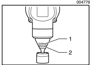
- Stainless steel gauge 2.5 mm (3/32")
- Mild steel gauge 3.2 mm (1/8")
The thickness of material to be cut depends upon the tensile strength of the material itself. The groove on the die holder acts as a thickness gauge for allowable cutting thickness. Do not attempt to cut any material which will not fit into this groove.
006439
| Max.cutting capacities | mm | ga |
| Steel up to 400 N/mm ^2 | 3.2 | 10 |
| Steel up to 600 N/mm ^2 | 2.5 | 13 |
| Steel up to 800 N/mm ^2 | 1.0 | 20 |
| Aluminum up to 200 N/mm ^2 | 3.5 | 10 |
Switch action
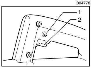
- Lock button
- Switch trigger
CAUTION:
- Before plugging in the tool, always check to see that the switch trigger actuates properly and returns to the "OFF" position when released.
- Switch can be locked in "ON" position for ease of operator comfort during extended use. Apply caution when locking tool in "ON" position and maintain firm grasp on tool.
To start the tool, simply pull the switch trigger. Release the switch trigger to stop.
For continuous operation, pull the switch trigger and then push in the lock button.
To stop the tool from the locked position, pull the switch trigger fully, then release it.
ASSEMBLY
CAUTION:
- Always be sure that the tool is switched off and unplugged before carrying out any work on the tool.
Punch replacement
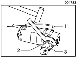
- Wrench
- Lock nut
- Die holder
Fit the wrench provided onto the lock nut and tap the handle lightly with a hammer to loosen the lock nut. Take off the die holder and use a wrench to remove the screw. Then remove the punch.
To install the punch, insert it into the punch holder with its cutting edge facing forward so that the pin in the punch holder fits into the groove in the punch. Install the screw and lock nut. Then tighten them securely.
004784
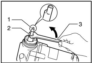
- Punch
- Screw
- Wrench
NOTE:
- When installing the screw and lock nut, be sure to tighten securely. If they become loose during operation, the tool may break down.
004785
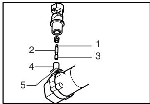
- Cutting edge
- Punch
- Groove
- Punch holder
- Pin
OPERATION
Pre-lubrication
Coat the cutting line with machine oil to increase the punch and die service life. This is particularly important when cutting aluminum.
Cutting method
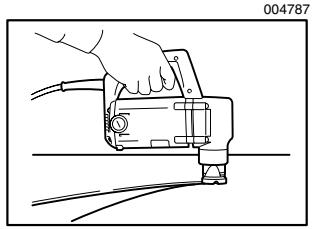
natural_image
Line drawing of a hand operating a mechanical device with wires (no text or symbols)Smooth cutting is achieved by holding the tool upright and applying gentle pressure in the cutting direction.
Apply tool oil to the punch about every 10 meters (32.8 feet) of mild steel or stainless steel to be cut. Light oil or kerosene should be used to keep an aluminum lubricated continuously. Failure to lubricate aluminum in the cut will cause chips to adhere to the tool, dulling the die and punch and increasing load on the motor.
Cutouts
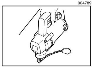
natural_image
Mechanical assembly diagram showing a linkage mechanism with no visible text or symbolsCutouts can be done by first opening a round hole of about 42 mm (1-5/8") diameter or more in the material.
Cutting stainless steel
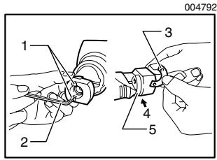
- Screw
- Hex wrench
- Washer
- Insert washer in between
- Die
There is more vibration when cutting stainless steel than mild steel. Less vibration and better cutting is possible by adding another washer (standard equipment) beneath the die.
Use the hex wrench provided to remove the two screws and insert the washer below the die. Replace screws and tighten securely.
MAINTENANCE
CAUTION:
- Always be sure that the tool is switched off and unplugged before attempting to perform inspection or maintenance.
Replace or sharpen punch and die after cutting the lengths indicated in the accompanying table. Their life, of course, depends upon the thickness of materials cut and lubrication conditions.
006440
| Punch | Replace after 150 m (492 ft.) of 3.2 mm (1/8") steel sheet |
| Die | Sharpen after 300 m (984 ft.) of 3.2 mm (1/8") steel sheet |
When cutting is poor even after replacing the punch, sharpen the die. Grind down the dull edge shown in the figure using a grinder. After rough-grinding the dull portion, finish with a dressing stone. Stock removal should be about 0.3 to 0.4 mm (1/64").
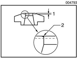
- Grind/sharpen; 0.3 - 0.4 mm (1/64")
- Remove dull portion
When installing ground die, a clearance of 3.5 to 4.0 mm (1/8" to 5/32") should be obtained by attaching one or two of the washer provided, as shown in the figure. Failure to have the proper clearance will result in vibration during cutting.
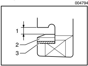
- 3.5 -4.0 mm (1/8" - 5/32")
- Die
- Washer
CAUTION:
- Secure installing screws carefully when installing. A loose screw can cause tool breakage during operation.
NOTE:
- The die can be sharpened two times. After two sharpenings, it should be replaced with new one.
Replacing carbon brushes
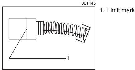
Remove and check the carbon brushes regularly. Replace when they wear down to the limit mark. Keep the carbon brushes clean and free to slip in the holders. Both carbon brushes should be replaced at the same time. Use only identical carbon brushes.
Use a screwdriver to remove the brush holder caps. Take out the worn carbon brushes, insert the new ones and secure the brush holder caps.
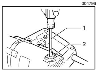
-
Screwdriver
-
Brush holder cap
To maintain product SAFETY and RELIABILITY, repairs, any other maintenance or adjustment should be performed by Makita Authorized or Factory Service Centers, always using Makita replacement parts.
ACCESSORIES
CAUTION:
- These accessories or attachments are recommended for use with your Makita tool specified in this manual. The use of any other accessories or attachments might present a risk of injury to persons. Only use accessory or attachment for its stated purpose.
If you need any assistance for more details regarding these accessories, ask your local Makita Service Center.
• Die
- Punch
- Hex wrench
- Wrench 50
• Die height adjustment washer
EN0006-1
MAKITA LIMITED ONE YEAR WARRANTY
Warranty Policy
Every Makita tool is thoroughly inspected and tested before leaving the factory. It is warranted to be free of defects from workmanship and materials for the period of ONE YEAR from the date of original purchase. Should any trouble develop during this one year period, return the COMPLETE tool, freight prepaid, to one of Makita's Factory or Authorized Service Centers. If inspection shows the trouble is caused by defective workmanship or material, Makita will repair (or at our option, replace) without charge.
This Warranty does not apply where:
• repairs have been made or attempted by others:
- repairs are required because of normal wear and tear:
- the tool has been abused, misused or improperly maintained:
• alterations have been made to the tool.
IN NO EVENT SHALL MAKITA BE LIABLE FOR ANY INDIRECT, INCIDENTAL OR CONSEQUENTIAL DAMAGES FROM THE SALE OR USE OF THE PRODUCT. THIS DISCLAIMER APPLIES BOTH DURING AND AFTER THE TERM OF THIS WARRANTY.
MAKITA DISCLAIMS LIABILITY FOR ANY IMPLIED WARRANTIES, INCLUDING IMPLIED WARRANTIES OF "MERCHANTABILITY" AND "FITNESS FOR A SPECIFIC PURPOSE," AFTER THE ONE YEAR TERM OF THIS WARRANTY.
This Warranty gives you specific legal rights, and you may also have other rights which vary from state to state. Some states do not allow the exclusion or limitation of incidental or consequential damages, so the above limitation or exclusion may not apply to you. Some states do not allow limitation on how long an implied warranty lasts, so the above limitation may not apply to you.
FRANÇAIS SPÉCIFICATIONS
- Tranchant
- Poinçon
- Rainure
- Porte-poinçon
- Broche
UTILISATION
Prègraissage
natural_image
Line drawing of a hand operating a handheld electric drill press (no text or symbols)natural_image
Technical line drawing of a mechanical device with no visible text or symbolsnatural_image
Line drawing of a hand operating a mechanical device with wires (no text or symbols)natural_image
Mechanical component diagram showing a lever mechanism with no visible text or symbolsnatural_image
Pure mechanical diagram showing a spring-loaded component with no text or symbols- Marca límite
Some dust created by power sanding, sawing, grinding, drilling, and other construction activities contains chemicals known to the State of California to cause cancer, birth defects or other reproductive harm. Some examples of these chemicals are:
- lead from lead-based paints,
• crystalline silica from bricks and cement and other masonry products, and
• arsenic and chromium from chemically-treated lumber.
Your risk from these exposures varies, depending on how often you do this type of work. To reduce your exposure to these chemicals: work in a well ventilated area, and work with approved safety equipment, such as those dust masks that are specially designed to filter out microscopic particles.
< USA solamente >
ADVERTENCIA
- GENERAL SAFETY RULES
- WARNING:
- SAVE THESE INSTRUCTIONS
- Work area safety
- Electrical safety
- Personal safety
- Power tool use and care
- Service
- SPECIFIC SAFETY RULES
- SAVE THESE INSTRUCTIONS.
- SYMBOLS
- FUNCTIONAL DESCRIPTION
- CAUTION:
- ASSEMBLY
- NOTE:
- OPERATION
- Pre-lubrication
- MAINTENANCE
- ACCESSORIES
- MAKITA LIMITED ONE YEAR WARRANTY
- Warranty Policy
- UTILISATION
- Prègraissage
- ADVERTENCIA
Brand : MAKITA
Model : JN3200
Category : Jigsaw