
4326 - Jigsaw MAKITA - Free user manual and instructions
Find the device manual for free 4326 MAKITA in PDF.

User questions about 4326 MAKITA
0 question about this device. Answer the ones you know or ask your own.
Ask a new question about this device
Download the instructions for your Jigsaw in PDF format for free! Find your manual 4326 - MAKITA and take your electronic device back in hand. On this page are published all the documents necessary for the use of your device. 4326 by MAKITA.
USER MANUAL 4326 MAKITA
INSTRUCTION MANUAL MANUEL D'INSTRUCTION MANUAL DE INSTRUCCIONES
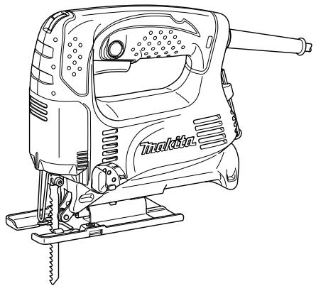
Jig Saw Scie sauteuse Sierra Caladora
4326 4327 4328 4329

natural_image
Line drawing of a J-shaped saw with handle and base mount (no text or symbols)008081

DOUBLE INSULATION DOUBLE ISOLATION DOBLE AISLAMIENTO
⚠ WARNING:
For your personal safety, READ and UNDERSTAND before using. SAVE THESE INSTRUCTIONS FOR FUTURE REFERENCE.
⚠️ AVERTISSEMENT:
| Model | 4326 | 4327 | 4328 | 4329 | |
| Length of stroke | 18 mm (11/16") | 18 mm (11/16") | 18 mm (11/16") | 18 mm (11/16") | |
| Max. cutting capacities | Wood | 65 mm (2-9/16") | 65 mm (2-9/16") | 65 mm (2-9/16") | 65 mm (2-9/16") |
| Mild steel | 6 mm (1/4") | 6 mm (1/4") | 6 mm (1/4") | 6 mm (1/4") | |
| Strokes per minute | 3,100/min | 500 - 3,100/min | 500 - 3,100/min | 500 - 3,100/min | |
| Overall length | 217 mm (8-1/2") (Steel base type) | 217 mm (8-1/2") (Steel base type) | 217 mm (8-1/2") | 223 mm (8-3/4") | |
| 223 mm (8-3/4") (Aluminum base type) | 223 mm (8-3/4") (Aluminum base type) | ||||
| Net weight | 1.8 kg (4.0 lbs) (Steel base type) | 1.8 kg (4.0 lbs) (Steel base type) | 1.8 kg (4.0 lbs) | 1.9 kg (4.2 lbs) | |
| 1.9 kg (4.2 lbs) (Aluminum base type) | 1.9 kg (4.2 lbs) (Aluminum base type) | ||||
- Due to our continuing programme of research and development, the specifications herein are subject to change without notice.
- Note: Specifications may differ from country to country.
GEA001-3
GENERAL SAFETY RULES
WARNING! Read all instructions. Failure to follow all instructions listed below may result in electric shock, fire and/or serious injury. The term "power tool" in all of the warnings listed below refers to your mains-operated (corded) power tool or battery-operated (cordless) power tool.
SAVE THESE INSTRUCTIONS.
Work area safety
- Keep work area clean and well lit. Cluttered and dark areas invite accidents.
- Do not operate power tools in explosive atmospheres, such as in the presence of flammable liquids, gases or dust. Power tools create sparks which may ignite the dust or fumes.
- Keep children and bystanders away while operating a power tool. Distractions can cause you to lose control.
Electrical Safety
- Power tool plugs must match the outlet. Never modify the plug in any way. Do not use any adapter plugs with earthed (grounded) power tools. Unmodified plugs and matching outlets will reduce risk of electric shock.
- Avoid body contact with earthed or grounded surfaces such as pipes, radiators, ranges and refrigerators. There is an increased risk of electric shock if your body is earthed or grounded.
- Do not expose power tools to rain or wet conditions. Water entering a power tool will increase the risk of electric shock.
- Do not abuse the cord. Never use the cord for
carrying, pulling or unplugging the power tool. Keep cord away from heat, oil, sharp edges or moving parts. Damaged or entangled cords increase the risk of electric shock.
- When operating a power tool outdoors, use an extension cord suitable for outdoor use. Use of a cord suitable for outdoor use reduces the risk of electric shock.
Personal Safety
- Stay alert, watch what you are doing and use common sense when operating a power tool. Do not use a power tool while you are tired or under the influence of drugs, alcohol or medication. A moment of inattention while operating power tools may result in serious personal injury.
-
Use safety equipment. Always wear eye protection. Safety equipment such as dust mask, non-skid safety shoes, hard hat, or hearing protection used for appropriate conditions will reduce personal injuries.
-
Avoid accidental starting. Ensure the switch is in the off-position before plugging in. Carrying power tools with your finger on the switch or plugging in power tools that have the switch on invites accidents.
-
Remove any adjusting key or wrench before turning the power tool on. A wrench or a key left attached to a rotating part of the power tool may result in personal injury.
-
Do not overreach. Keep proper footing and balance at all times. This enables better control of the power tool in unexpected situations.
-
Dress properly. Do not wear loose clothing or jewellery. Keep your hair, clothing, and gloves
away from moving parts. Loose clothes, jewellery or long hair can be caught in moving parts.
- If devices are provided for the connection of dust extraction and collection facilities, ensure these are connected and properly used. Use of these devices can reduce dust-related hazards.
Power tool use and care
-
Do not force the power tool. Use the correct power tool for your application. The correct power tool will do the job better and safer at the rate for which it was designed.
-
Do not use the power tool if the switch does not turn it on and off. Any power tool that cannot be controlled with the switch is dangerous and must be repaired.
-
Disconnect the plug from the power source and/or the battery pack from the power tool before making any adjustments, changing accessories, or storing power tools. Such preventive safety measures reduce the risk of starting the power tool accidentally.
-
Store idle power tools out of the reach of children and do not allow persons unfamiliar with the power tool or these instructions to operate the power tool. Power tools are dangerous in the hands of untrained users.
-
Maintain power tools. Check for misalignment or binding of moving parts, breakage of parts and any other condition that may affect the power tools operation. If damaged, have the power tool repaired before use. Many accidents are caused by poorly maintained power tools.
-
Keep cutting tools sharp and clean. Properly maintained cutting tools with sharp cutting edges are less likely to bind and are easier to control.
-
Use the power tool, accessories and tool bits etc. in accordance with these instructions and in the manner intended for the particular type of power tool, taking into account the working conditions and the work to be performed. Use of the power tool for operations different from those intended could result in a hazardous situation.
SERVICE
-
Have your power tool serviced by a qualified repair person using only identical replacement parts. This will ensure that the safety of the power tool is maintained.
-
Follow instruction for lubricating and changing accessories.
-
Keep handles dry, clean and free from oil and grease.
GEB016-1
SPECIFIC SAFETY RULES
DO NOT let comfort or familiarity with product (gained from repeated use) replace strict adherence to jig saw safety rules. If you use this tool unsafely or incorrectly, you can suffer serious personal injury.
- Hold power tools by insulated gripping surfaces when performing an operation where the cutting tool may contact hidden wiring or its own cord. Contact with a "live" wire will make exposed metal parts of the tool "live" and shock the operator.
- Use clamps or another practical way to secure and support the workpiece to a stable platform. Holding the work by hand or against your body leaves it unstable and may lead to loss of control.
- Always use safety glasses or goggles. Ordinary eye or sun glasses are NOT safety glasses.
- Avoid cutting nails. Inspect workpiece for any nails and remove them before operation.
- Do not cut oversize workpiece.
- Check for the proper clearance beyond the workpiece before cutting so that the blade will not strike the floor, workbench, etc.
- Hold the tool firmly.
- Make sure the blade is not contacting the workpiece before the switch is turned on.
- Keep hands away from moving parts.
- Do not leave the tool running. Operate the tool only when hand-held.
- Always switch off and wait for the blade to come to a complete stop before removing the blade from the workpiece.
- Do not touch the blade or the workpiece immediately after operation; they may be extremely hot and could burn your skin.
- Do not operate the tool at no-load unnecessarily.
- Some material contains chemicals which may be toxic. Take caution to prevent dust inhalation and skin contact. Follow material supplier safety data.
- Always use the correct dust mask/respirator for the material and application you are working with.
SAVE THESE INSTRUCTIONS.
⚠ WARNING:
MISUSE or failure to follow the safety rules stated in this instruction manual may cause serious personal
injury.
USD201-2
Symbols
The followings show the symbols used for tool.
v · volts
A · amperes
Hz · hertz
\~ · alternating current
n_0 · no load speed
Class II Construction
... /min · revolutions or reciprocation per minute r/min
FUNCTIONAL DESCRIPTION
CAUTION:
• Always be sure that the tool is switched off and unplugged before adjusting or checking function on the tool.
Selecting the cutting action (For models 4328/4329)
natural_image
Technical line drawing of a sewing machine needle and base (no text or symbols)008153
- Cutting action changing lever
This tool can be operated with an orbital or a straight line (up and down) cutting action. The orbital cutting action thrusts the blade forward on the cutting stroke and greatly increases cutting speed.
To change the cutting action, just turn the cutting action changing lever to the desired cutting action position.
Refer to the table to select the appropriate cutting action.
| Position | Cutting action | Applications |
| 0 | Straight line cutting action | For cutting mild steel, stainless steel and plastics. |
| For clean cuts in wood and plywood. | ||
| I | Small orbit cutting action | For cutting mild steel, aluminum and hard wood. |
| II | Medium orbit cutting action | For cutting wood and plywood. |
| For fast cutting in aluminum and mild steel. | ||
| III | Large orbit cutting action | For fast cutting in wood and plywood. |
006582
Switch action

008082
- Switch trigger
- Lock button
⚠️CAUTION:
- Before plugging in the tool, always check to see that the switch trigger actuates properly and returns to the "OFF" position when released.
- Switch can be locked in "ON" position for ease of operator comfort during extended use. Apply caution when locking tool in "ON" position and maintain firm grasp on tool.
To start the tool, simply pull the switch trigger. Release the switch trigger to stop.
For continuous operation, pull the switch trigger and then push in the lock button.
To stop the tool from the locked position, pull the switch trigger fully, then release it.
Speed adjusting dial (For models 4327/4328/4329)
- Speed adjusting dial
008167
The tool speed can be infinitely adjusted between 500 and 3,100 strokes per minute by turning the adjusting dial. Higher speed is obtained when the dial is turned in the direction of number 6; lower speed is obtained when it is turned in the direction of number 1.
Refer to the table to select the proper speed for the workpiece to be cut. However, the appropriate speed may differ with the type or thickness of the workpiece. In general, higher speeds will allow you to cut workpieces faster but the service life of the blade will be reduced.
| Workpiece to be cut | Number on adjusting dial |
| Wood | 5 - 6 |
| Mild steel | 3 - 6 |
| Stainless steel | 3 - 4 |
| Aluminum | 3 - 6 |
| Plastics | 1 - 4 |
006583
CAUTION:
- If the tool is operated continuously at low speeds for a long time, the motor will get overloaded and heated up.
- The speed adjusting dial can be turned only as far as 6 and back to 1. Do not force it past 6 or 1, or the speed adjusting function may no longer work.
ASSEMBLY
CAUTION:
• Always be sure that the tool is switched off and unplugged before carrying out any work on the tool.
Installing or removing saw blade
008083
- Blade holder
- Bolt
- Hex wrench
⚠️CAUTION:
• Always clean out all chips or foreign matter adhering to the blade and/or blade holder. Failure to do so may cause insufficient tightening of the blade, resulting in a serious personal injury.
- Do not touch the blade or the workpiece immediately after operation; they may be extremely hot and could burn your skin.
• Always secure the blade firmly. Insufficient tightening of the blade may cause blade breakage or serious personal injury.
- Use only B type blades. Using blades other than B type blades causes insufficient tightening of the blade, resulting in a serious personal injury.
To install the blade, loosen the bolt counterclockwise on the blade holder with the hex wrench.
With the blade teeth facing forward, insert the blade into the blade holder as far as it will go. Make sure that the back edge of the blade fits into the roller. Then tighten the bolt clockwise to secure the blade.
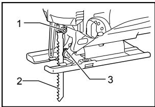
008084
- Bolt
- Blade
- Roller
To remove the blade, follow the installation procedure in reverse.
NOTE:
• Occasionally lubricate the roller.
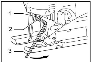
Hex wrench storage
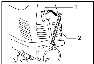
008085
- Hook
- Hex wrench
When not in use, store the hex wrench as shown in the figure to keep it from being lost.
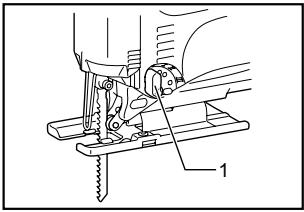
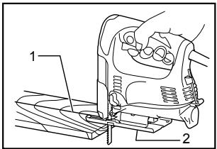
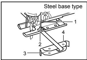
Adjusting roller (For models 4326/4327)
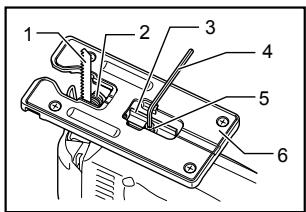
008154
- Blade
- Roller
- Retainer
- Hex wrench
- Bolt
- Base
Loosen the bolt on the back of the base with the hex wrench. Move the retainer so that the roller contacts the blade lightly. Then tighten the bolt to secure the base and the retainer.
NOTE:
• Occasionally lubricate the roller.
Dust cover
008086
- Dust cover
CAUTION:
• Always wear safety goggles even when operating the tool with the dust cover lowered.
Lower the dust cover to prevent chips from flying. However, when making bevel cuts, raise it all the way.
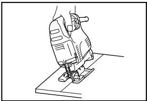
OPERATION
⚠️CAUTION:
• Always hold the base flush with the workpiece. Failure to do so may cause blade breakage, resulting in a serious injury.
- Advance the tool very slowly when cutting curves or scrolling. Forcing the tool may cause a slanted cutting surface and blade breakage.
Turn the tool on without the blade making any contact and wait until the blade attains full speed. Then rest the base flat on the workpiece and gently move the tool forward along the previously marked cutting line.
008087
- Cutting line
- Base
Bevel cutting
natural_image
Line drawing of a sewing machine on a base (no text or symbols)008088
CAUTION:
• Always be sure that the tool is switched off and unplugged before tilting the base.
- Raise the dust cover all the way before making bevel cuts.
With the base tilted, you can make bevel cuts at any angle between 0^ and 45^ (left or right).
Loosen the bolt on the back of the base with the hex wrench. Move the base so that the bolt is positioned in the center of the cross-shaped slot in the base.
008089
- Hex wrench
- Bolt
- Base
Tilt the base until the desired bevel angle is obtained. The edge of the motor housing indicates the bevel angle by graduations. Then tighten the bolt to secure the base.
008090
- Edge
- Graduation
Front flush cuts
008091
- Hex wrench
- Bolt
- Base
Loosen the bolt on the back of the base with the hex wrench and slide the base all the way back. Then tighten the bolt to secure the base.
Cutouts
Cutouts can be made with either of two methods A or B.
A) Boring a starting hole
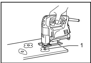
natural_image
Line drawing of a sewing machine on a base, showing foot and legs components (no text or symbols)008092
- Starting hole
For internal cutouts without a lead-in cut from an edge, pre-drill a starting hole 12 mm or more in
diameter. Insert the blade into this hole to start your cut.
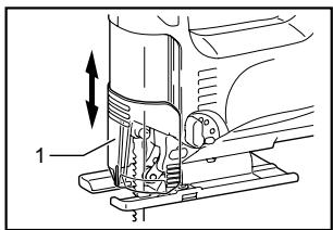
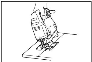
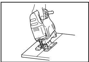
B) Plunge cutting
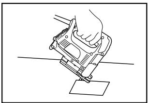
natural_image
Line drawing of a hand using a mechanical tool to press or install a sheet (no text or symbols)008093
You need not bore a starting hole or make a lead-in cut if you carefully do as follows.
(1) Tilt the tool up on the front edge of the base with the blade point positioned just above the workpiece surface.
(2) Apply pressure to the tool so that the front edge of the base will not move when you switch on the tool and gently lower the back end of the tool slowly.
(3) As the blade pierces the workpiece, slowly lower the base of the tool down onto the workpiece surface.
(4) Complete the cut in the normal manner.
Finishing edges
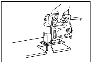
natural_image
Line drawing of a hand operating a mechanical device with a tool, no text or symbols present008094
To trim edges or make dimensional adjustments, run the blade lightly along the cut edges.
Metal cutting
Always use a suitable coolant (cutting oil) when cutting metal. Failure to do so will cause significant blade wear. The underside of the workpiece can be greased instead of using a coolant.
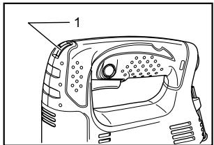
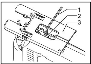
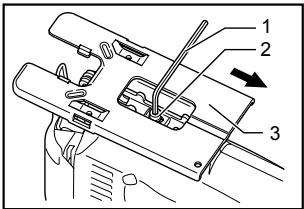
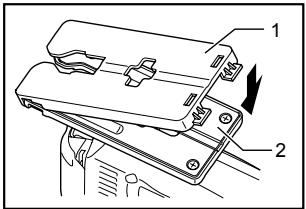
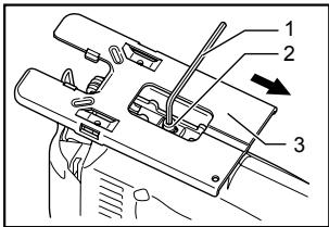
Dust extraction
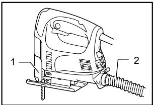
008095
1. Dust cover
2. Hose
Clean cutting operations can be performed by connecting this tool to a Makita vacuum cleaner. Insert the hose of the vacuum cleaner into the hole at the rear of the tool. Lower the dust cover before operation.
NOTE:
- Dust extraction cannot be performed when making bevel cuts.
Rip fence (optional accessory)
CAUTION:
• Always be sure that the tool is switched off and unplugged before installing or removing accessories.
- Straight cuts
008096
- Rip fence (Guide rule)
When repeatedly cutting widths of 160 mm or less, use of the rip fence will assure fast, clean, straight cuts.
008097
- Rip fence (Guide rule)
To install, insert the rip fence into the rectangular hole on the side of the base with the fence guide facing down. Slide the rip fence to the desired cutting width position, then tighten the bolt to secure it.
002776
1. Hex wrench
2. Bolt
3. Rip fence (Guide rule)
4. Guide facing
005454
1. Bolt
2. Fence guide
3. Hex wrench
4. Rip fence (Guide rule)
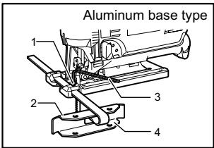
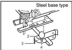
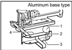
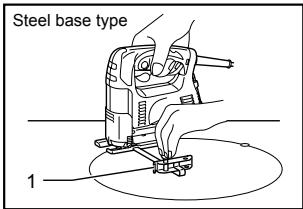
- Circular cuts
002777
1. Treaded knob
2. Guide facing
3. Rip fence (Guide rule)
4. Pin
005455
1. Threaded knob
2. Pin
3. Rip fence (Guide rule)
4. Fence guide
008098
1. Rip fence (Guide rule)
008099
- Rip fence (Guide rule)
When cutting circles or arcs of 170 mm or less in radius, install the rip fence as follows.
Insert the rip fence into the rectangular hole on the side of the base with the fence guide facing up. Insert the circular guide pin through either of the two holes on the fence guide. Screw the threaded knob onto the pin to secure the pin.
Now slide the rip fence to the desired cutting radius, and tighten the bolt to secure it in place. Then move the base all the way forward.
NOTE:
• Always use blades No. B-17, B-18, B-26 or B-27 when cutting circles or arcs.
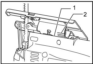
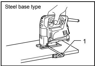
Anti-splintering device for steel base (optional accessory)
008100
- Anti-splintering device
- Protrusions
For splinter-free cuts, the anti-splintering device can be used. To install the anti-splintering device, move the base all the way forward and insert it between the two protrusions of the base.
NOTE:
- The anti-splintering device cannot be used when making bevel cuts.
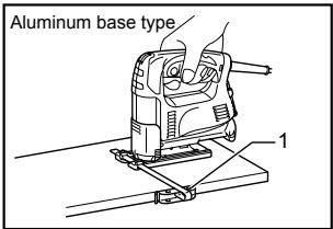
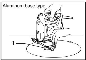
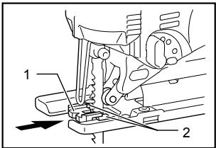
Anti-splintering device for aluminum base (Optional accessory)
008101
- Anti-splintering device
- Aluminum base
For splinter-free cuts, the anti-splintering device can be used. To install the anti-splintering device, move the tool base all the way forward and fit it from the back of tool base. When you use the cover plate, install the anti-splintering device onto the cover plate.
⚠️CAUTION:
- The anti-splintering device cannot be used when making bevel cuts.
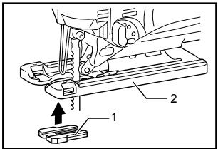
Cover plate for aluminum base (Optional accessory)
008102
- Cover plate
- Aluminum base
Use the cover plate when cutting decorative veneers, plastics, etc. It protects sensitive or delicate surfaces from damage. Fit it on the back of the tool base.
MAINTENANCE
⚠️CAUTION:
• Always be sure that the tool is switched off and unplugged before attempting to perform inspection or maintenance.
To maintain product SAFETY and RELIABILITY, repairs, carbon brush inspection and replacement, any other maintenance or adjustment should be performed by Makita Authorized Service Centers, always using Makita replacement parts.
ACCESSORIES
CAUTION:
- These accessories or attachments are recommended for use with your Makita tool specified in this manual. The use of any other accessories or attachments might present a risk of injury to persons. Only use accessory or attachment for its stated purpose.
If you need any assistance for more details regarding these accessories, ask your local Makita Service Center.
• Jig saw blades
- Hex wrench 3
• Rip fence (guide rule) set
• Anti-splintering device
• Hose (For vacuum cleaner)
• Cover plate (For aluminum base type)
MAKITA LIMITED ONE YEAR WARRANTY
Warranty Policy
Every Makita tool is thoroughly inspected and tested before leaving the factory. It is warranted to be free of defects from workmanship and materials for the period of ONE YEAR from the date of original purchase. Should any trouble develop during this one year period, return the COMPLETE tool, freight prepaid, to one of Makita's Factory or Authorized Service Centers. If inspection shows the trouble is caused by defective workmanship or material, Makita will repair (or at our option, replace) without charge.
This Warranty does not apply where:
• repairs have been made or attempted by others:
- repairs are required because of normal wear and tear:
- the tool has been abused, misused or improperly maintained:
• alterations have been made to the tool.
IN NO EVENT SHALL MAKITA BE LIABLE FOR ANY INDIRECT, INCIDENTAL OR CONSEQUENTIAL DAMAGES FROM THE SALE OR USE OF THE PRODUCT. THIS DISCLAIMER APPLIES BOTH DURING AND AFTER THE TERM OF THIS WARRANTY.
MAKITA DISCLAIMS LIABILITY FOR ANY IMPLIED WARRANTIES, INCLUDING IMPLIED WARRANTIES OF "MERCHANTABILITY" AND "FITNESS FOR A SPECIFIC PURPOSE," AFTER THE ONE YEAR TERM OF THIS WARRANTY.
This Warranty gives you specific legal rights, and you may also have other rights which vary from state to state. Some states do not allow the exclusion or limitation of incidental or consequential damages, so the above limitation or exclusion may not apply to you. Some states do not allow limitation on how long an implied warranty lasts, so the above limitation may not apply to you.
EN0006-1
FRANÇAIS
SPÉCIFICATIONS
| Modèle | 4326 | 4327 | 4328 | 4329 | |
| Longueur de frappe | 18 mm (11/16") | 18 mm (11/16") | 18 mm (11/16") | 18 mm (11/16") | |
| Capacités de coupe max. | Bois | 65 mm (2-9/16") | 65 mm (2-9/16") | 65 mm (2-9/16") | 65 mm (2-9/16") |
| Acier doux | 6 mm (1/4") | 6 mm (1/4") | 6 mm (1/4") | 6 mm (1/4") | |
| Nombre d'impacts par minutes | 3,100/min | 500 - 3,100/min | 500 - 3,100/min | 500 - 3,100/min | |
| Longueur totale | 217 mm (8-1/2")(Avec base d'acier) | 217 mm (8-1/2")(Avec base d'acier) | 217 mm (8-1/2") | 223 mm (8-3/4") | |
| 223 mm (8-3/4")(Type de base en aluminium) | 223 mm (8-3/4")(Type de base en aluminium) | ||||
| Poids net | 1.8 kg (4.0 lbs)(Avec base d'acier) | 1.8 kg (4.0 lbs)(Avec base d'acier) | 1.8 kg (4.0 lbs) | 1.9 kg (4.2 lbs) | |
| 1.9 kg (4.2 lbs)(Type de base en aluminium) | 1.9 kg (4.2 lbs)(Type de base en aluminium) | ||||
natural_image
Technical line drawing of a sewing machine needle and base (no text or symbols)008082
008083
- Porte-lame
- Boulon
- Clé hexagonale
ATTENTION:
008084
- Boulon
- Fer
- Rouleau
008085
- Crochet
- Clé hexagonale
008154
008086
- Capuchon anti-poussière
ATTENTION:
008087
- Ligne de coupe
- Base
Coupe en biseau
natural_image
Line drawing of a sewing machine on a base (no text or symbols)008088
ATTENTION:
008089
- Clé hexagonale
- Boulon
- Base
008090
- Bord
- Graduation
008091
- Clé hexagonale
- Boulon
- Base
natural_image
Line drawing of a sewing machine on a workbench, showing foot and fabric components (no text or symbols)008092
- Trou de départ
natural_image
Line drawing of a hand using a mechanical tool to cut or mark a flat surface (no text or symbols)008093
natural_image
Line drawing of a hand using a power tool on a base (no text or symbols)008094
008095
- Capuchon anti-poussière
- Tuyau
008100
- Dispositif anti-fente
- Saillies
008101
- Dispositif anti-fente
- Base en aluminium
008102
natural_image
Technical line drawing of a sewing machine with a foot adjusting the base (no text or symbols)008082
008083
- Porta-útil
- Tornillo
- Llave hexagonal
⚠️PRECAUCIÓN:
008084
- Tornillo
- Disco
- Rodillo
008085
- Gancho
- Llave hexagonal
008154
- Disco
- Rodillo
- Retenedor
- Llave hexagonal
- Tornillo
- Base
008086
008087
- Línea de corte
- Base
Corte en bisel
natural_image
Line drawing of a sewing machine on a base (no text or symbols)008088
⚠️PRECAUCIÓN:
008089
- Llave hexagonal
- Tornillo
- Base
008090
- Borde
- Graduación
Cortes a ras frontales
008091
- Llave hexagonal
- Tornillo
- Base
natural_image
Line drawing of a sewing machine on a base, showing components and parts (no text or symbols)008092
- Agujero de inicio
natural_image
Line drawing of a hand using a mechanical tool to press or install a sheet of paper (no text or symbols present)008093
natural_image
Line drawing of a hand operating a small electric drill bit on a workbench (no text or symbols)008094
008100
008101
008102
Some dust created by power sanding, sawing, grinding, drilling, and other construction activities contains chemicals known to the State of California to cause cancer, birth defects or other reproductive harm. Some examples of these chemicals are:
- lead from lead-based paints,
• crystalline silica from bricks and cement and other masonry products, and
• arsenic and chromium from chemically-treated lumber.
Your risk from these exposures varies, depending on how often you do this type of work. To reduce your exposure to these chemicals: work in a well ventilated area, and work with approved safety equipment, such as those dust masks that are specially designed to filter out microscopic particles.
< USA solamente >