USER MANUAL 4351CT MAKITA
INSTRUCTION MANUAL
MANUEL D'INSTRUCTION
MANUAL DE INSTRUCCIONES
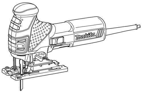
Jig Saw Scie sauteuse Sierra Caladora
4351T
4351CT
4351FCT

natural_image
Line drawing of a manual pusher with visible blade and base mount (no text or symbols)
008029

DOUBLE INSULATION
DOUBLE ISOLATION
DOBLE AISLAMIENTO
⚠ WARNING:
For your personal safety, READ and UNDERSTAND before using. SAVE THESE INSTRUCTIONS FOR FUTURE REFERENCE.
⚠️ AVERTISSEMENT:
| Model | 4351T | 4351CT / 4351FCT |
| Length of stroke | 26 mm (1") |
| Cutting capacities | Wood | 135 mm (5-5/16") |
| Steel | 10 mm (3/8") |
| Aluminum | 20 mm (25/32") |
| Strokes per minute | 2,800/min. | 800 - 2,800/min. |
| Overall length | 271 mm (10-11/16") |
| Net weight | 2.4 kg (5.3 lbs) | 2.5 kg (5.5 lbs) |
- Due to our continuing programme of research and development, the specifications herein are subject to change without notice.
• Note: Specifications may differ from country to country.
GEA001-3
GENERAL SAFETY RULES
WARNING! Read all instructions. Failure to follow all instructions listed below may result in electric shock, fire and/or serious injury. The term "power tool" in all of the warnings listed below refers to your mains-operated (corded) power tool or battery-operated (cordless) power tool.
SAVE THESE INSTRUCTIONS.
Work area safety
- Keep work area clean and well lit. Cluttered and dark areas invite accidents.
- Do not operate power tools in explosive atmospheres, such as in the presence of flammable liquids, gases or dust. Power tools create sparks which may ignite the dust or fumes.
- Keep children and bystanders away while operating a power tool. Distractions can cause you to lose control.
Electrical Safety
- Power tool plugs must match the outlet. Never modify the plug in any way. Do not use any adapter plugs with earthed (grounded) power tools. Unmodified plugs and matching outlets will reduce risk of electric shock.
- Avoid body contact with earthed or grounded surfaces such as pipes, radiators, ranges and refrigerators. There is an increased risk of electric shock if your body is earthed or grounded.
- Do not expose power tools to rain or wet conditions. Water entering a power tool will increase the risk of electric shock.
- Do not abuse the cord. Never use the cord for carrying, pulling or unplugging the power tool. Keep cord away from heat, oil, sharp edges or moving parts. Damaged or entangled cords increase the risk of electric shock.
- When operating a power tool outdoors, use an
extension cord suitable for outdoor use. Use of a cord suitable for outdoor use reduces the risk of electric shock.
Personal Safety
- Stay alert, watch what you are doing and use common sense when operating a power tool. Do not use a power tool while you are tired or under the influence of drugs, alcohol or medication. A moment of inattention while operating power tools may result in serious personal injury.
- Use safety equipment. Always wear eye protection. Safety equipment such as dust mask, non-skid safety shoes, hard hat, or hearing protection used for appropriate conditions will reduce personal injuries.
- Avoid accidental starting. Ensure the switch is in the off-position before plugging in. Carrying power tools with your finger on the switch or plugging in power tools that have the switch on invites accidents.
- Remove any adjusting key or wrench before turning the power tool on. A wrench or a key left attached to a rotating part of the power tool may result in personal injury.
- Do not overreach. Keep proper footing and balance at all times. This enables better control of the power tool in unexpected situations.
- Dress properly. Do not wear loose clothing or jewellery. Keep your hair, clothing, and gloves away from moving parts. Loose clothes, jewellery or long hair can be caught in moving parts.
- If devices are provided for the connection of dust extraction and collection facilities, ensure these are connected and properly used. Use of these devices can reduce dust-related hazards.
- Do not force the power tool. Use the correct
power tool for your application. The correct power tool will do the job better and safer at the rate for which it was designed.
-
Do not use the power tool if the switch does not turn it on and off. Any power tool that cannot be controlled with the switch is dangerous and must be repaired.
-
Disconnect the plug from the power source and/or the battery pack from the power tool before making any adjustments, changing accessories, or storing power tools. Such preventive safety measures reduce the risk of starting the power tool accidentally.
-
Store idle power tools out of the reach of children and do not allow persons unfamiliar with the power tool or these instructions to operate the power tool. Power tools are dangerous in the hands of untrained users.
-
Maintain power tools. Check for misalignment or binding of moving parts, breakage of parts and any other condition that may affect the power tools operation. If damaged, have the power tool repaired before use. Many accidents are caused by poorly maintained power tools.
-
Keep cutting tools sharp and clean. Properly maintained cutting tools with sharp cutting edges are less likely to bind and are easier to control.
-
Use the power tool, accessories and tool bits etc. in accordance with these instructions and in the manner intended for the particular type of power tool, taking into account the working conditions and the work to be performed. Use of the power tool for operations different from those intended could result in a hazardous situation.
SERVICE
-
Have your power tool serviced by a qualified repair person using only identical replacement parts. This will ensure that the safety of the power tool is maintained.
-
Follow instruction for lubricating and changing accessories.
-
Keep handles dry, clean and free from oil and grease.
GEB016-1
SPECIFIC SAFETY RULES
DO NOT let comfort or familiarity with product (gained from repeated use) replace strict adherence to jig saw safety rules. If you use this tool unsafely or incorrectly, you can suffer serious personal injury.
- Hold power tools by insulated gripping surfaces when performing an operation where the cutting tool may contact hidden wiring or
its own cord. Contact with a "live" wire will make exposed metal parts of the tool "live" and shock the operator.
-
Use clamps or another practical way to secure and support the workpiece to a stable platform. Holding the work by hand or against your body leaves it unstable and may lead to loss of control.
-
Always use safety glasses or goggles. Ordinary eye or sun glasses are NOT safety glasses.
-
Avoid cutting nails. Inspect workpiece for any nails and remove them before operation.
-
Do not cut oversize workpiece.
-
Check for the proper clearance beyond the workpiece before cutting so that the blade will not strike the floor, workbench, etc.
-
Hold the tool firmly.
-
Make sure the blade is not contacting the workpiece before the switch is turned on.
-
Keep hands away from moving parts.
-
Do not leave the tool running. Operate the tool only when hand-held.
-
Always switch off and wait for the blade to come to a complete stop before removing the blade from the workpiece.
-
Do not touch the blade or the workpiece immediately after operation; they may be extremely hot and could burn your skin.
-
Do not operate the tool at no-load unnecessarily.
-
Some material contains chemicals which may be toxic. Take caution to prevent dust inhalation and skin contact. Follow material supplier safety data.
-
Always use the correct dust mask/respirator for the material and application you are working with.
SAVE THESE INSTRUCTIONS.
⚠ WARNING:
MISUSE or failure to follow the safety rules stated in this instruction manual may cause serious personal injury.
USD201-2
Symbols
The followings show the symbols used for tool.
v · volts
A · amperes
Hz · hertz
\~ · alternating current
n. no load speed
Class II Construction
... /min · revolutions or reciprocation per minute
r/min
FUNCTIONAL DESCRIPTION
CAUTION:
• Always be sure that the tool is switched off and unplugged before adjusting or checking function on the tool.
Selecting the cutting action
natural_image
Technical line drawing of a sewing machine with no visible text or symbols
008030
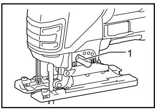
- Cutting action changing lever
This tool can be operated with an orbital or a straight line (up and down) cutting action. The orbital cutting action thrusts the blade forward on the cutting stroke and greatly increases cutting speed.
To change the cutting action, just turn the cutting action changing lever to the desired cutting action position. Refer to the table to select the appropriate cutting action.
| Position | Cutting action | Applications |
| 0 | Straight line cutting action | For cutting mild steel, stainless steel and plastics. For clean cuts in wood and plywood. |
| I | Small orbit cutting action | For cutting mild steel, aluminum and hard wood. |
| II | Medium orbit cutting action | For cutting wood and plywood. For fast cutting in aluminum and mild steel. |
| III | Large orbit cutting action | For fast cutting in wood and plywood. |
006376
Switch action
natural_image
Technical line drawing of a mechanical component with labeled parts (no text or symbols present)
008031
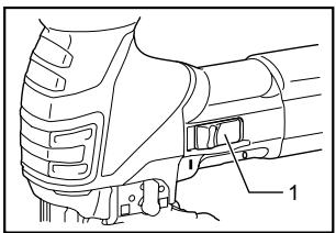
- Switch lever
⚠️CAUTION:
• Before plugging in the tool, always be sure that the tool is switched off.
To start the tool, slide the switch lever to the "I" position. To stop the tool, slide the switch lever to the "O" position.
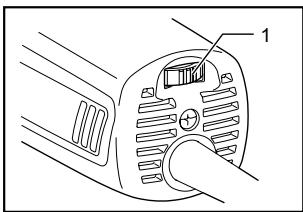
Speed adjusting dial
For 4351CT, 4351FCT
008032
- Speed adjusting dial
The tool speed can be infinitely adjusted between 800 and 2,800 strokes per minute by turning the adjusting dial. Higher speed is obtained when the dial is turned in the direction of number 5; lower speed is obtained when it is turned in the direction of number 1.
Refer to the table to select the proper speed for the workpiece to be cut. However, the appropriate speed may differ with the type or thickness of the workpiece. In general, higher speeds will allow you to cut workpieces
faster but the service life of the blade will be reduced.
| Workpiece to be cut | Number on adjusting dial |
| Wood | 4 - 5 |
| Mild steel | 3 - 5 |
| Stainless steel | 3 - 4 |
| Aluminum | 3 - 5 |
| Plastics | 1 - 4 |
006368
CAUTION:
- The speed adjusting dial can be turned only as far as 5 and back to 1. Do not force it past 5 or 1, or the speed adjusting function may no longer work.
The tools equipped with electronic function are easy to operate because of the following features.
Constant speed control
Electronic speed control for obtaining constant speed. Possible to get fine finish, because the rotating speed is kept constant even under load condition.
Soft start feature
Safety and soft start because of suppressed starting shock.
Lighting up the lamps
For 4351FCT only
CAUTION:
- Do not look in the light or see the source of light directly.
To turn on the lamp, pull the trigger. Release the trigger to turn it off.
NOTE:
- Use a dry cloth to wipe the dirt off the lens of lamp. Be careful not to scratch the lens of lamp, or it may lower the illumination.
ASSEMBLY
CAUTION:
• Always be sure that the tool is switched off and unplugged before carrying out any work on the tool.
Installing or removing saw blade
CAUTION:
• Always clean out all chips or foreign matter adhering to the blade and/or blade holder. Failure to do so may cause insufficient tightening of the blade, resulting in a serious personal injury.
- Do not touch the blade or the workpiece immediately after operation; they may be extremely hot and could burn your skin.
- Tighten the saw blade securely. Failure to do so may cause a serious injury.
- When you remove the saw blade, be careful not to hurt your fingers with the top of the blade or the tips of workpiece.
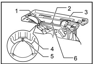
To install the blade, open the tool opener to the position shown in the figure.
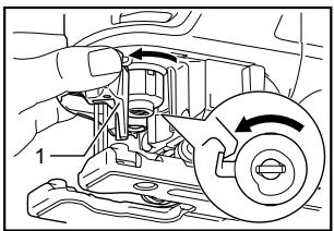
- Tool opener
008007
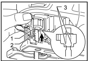
Keeping that situation, insert the saw blade into the blade clamp as far as the two protrusions of the blade can not be seen.
-
Blade clamp
-
Jig saw blade
-
Protrusions
008008
Return the tool opener to its original position.
After installing, always make sure that the blade is securely held in place by trying to pull it out.
⚠️CAUTION:
- Do not open the tool opener excessively, or it may cause tool damage.
To remove the blade, open the tool opener to the position shown in the figure. Pull the saw blade out toward the base.
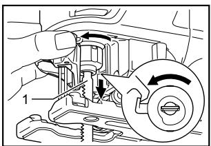
- Jig saw blade
008009
NOTE:
• Occasionally lubricate the roller.
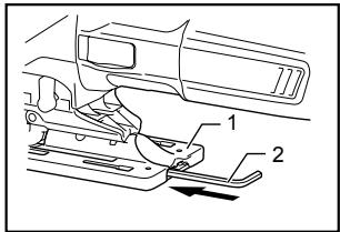
Hex wrench storage
008033
- Base
- Hex wrench
When not in use, the hex wrench can be conveniently stored.
Anti-splintering device
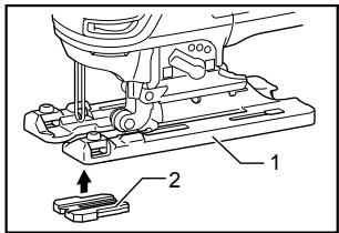
008028
- Base
- Anti-splintering device
For splinter-free cuts, the anti-splintering device can be used. To install the anti-splintering device, move the tool base all the way forward and fit it from the back of tool base. When you use the cover plate, install the anti-splintering device onto the cover plate.
CAUTION:
- The anti-splintering device cannot be used when making bevel cuts.
Cover plate
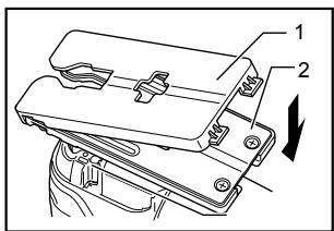
008027
- Cover plate
- Base
Use the cover plate when cutting decorative veneers, plastics, etc. It protects sensitive or delicate surfaces from damage. Fit it on the back of the tool base.
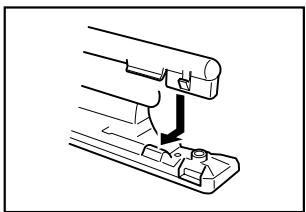
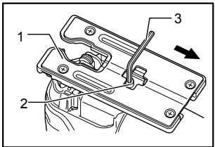
The dust nozzle (optional accessory) is recommended to perform clean cutting operations.
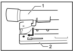
001921
- Dust nozzle
- Base
- Dust nozzle
To attach the dust nozzle on the tool, insert the hook of dust nozzle into the hole in the base.
The dust nozzle can be installed on either left or right side of the base.
natural_image
Technical line drawing of a mechanical assembly with a lever and base component (no text or symbols)
001922
Then connect a Makita vacuum cleaner to the dust nozzle.
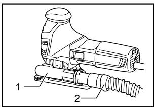
008039
- Dust nozzle
- Hose for vacuum cleaner
⚠️CAUTION:
- If you try to remove the dust nozzle forcibly, the hook of the dust nozzle can be diminished and removed unintentionally during operation.
OPERATION
⚠️CAUTION:
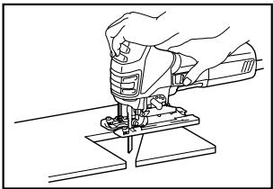
- Hold the tool firmly with one hand on the switch handle and the other hand on the front grip when performing the tool.
• Always hold the base flush with the workpiece. Failure to do so may cause blade breakage, resulting in a serious injury.
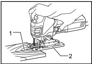
008034
- Cutting line
- Base
Turn the tool on without the blade making any contact and wait until the blade attains full speed. Then rest the base flat on the workpiece and gently move the tool forward along the previously marked cutting line.
When cutting curves, advance the tool very slowly.
Bevel cutting
natural_image
Line drawing of hands using a sewing machine to adjust or install a component (no text or symbols present)
008035
CAUTION:
• Always be sure that the tool is switched off and unplugged before tilting the base.
With the base tilted, you can make bevel cuts at any angle between 0^ and 45^ (left or right).
Loosen the bolt on the back of the base with the hex wrench. Move the base so that the bolt is positioned in the center of the bevel slot in the base.
008013
- Base
- Bolt
- Hex wrench
Tilt the base until the desired bevel angle is obtained. The V-notch of the gear housing indicates the bevel angle by graduations. Then tighten the bolt firmly to secure the base.
008014
- Graduation
- Bevel slot
- Base
- Gear housing
- V-notch
- Bolt
Front flush cuts
008015
- Base
- Bolt
- Hex wrench
Loosen the bolt on the back of the base with the hex wrench and slide the base all the way back. Then tighten the bolt to secure the base.
Cutouts
Cutouts can be made with either of two methods A or B.
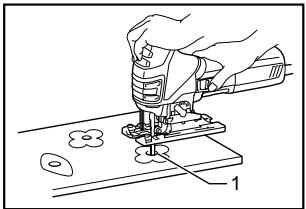
A) Boring a starting hole:
natural_image
Line drawing of a hand using a sewing machine to cut fabric or paper (no text or symbols present)
008036
- Starting hole
For internal cutouts without a lead-in cut from an edge, pre-drill a starting hole 12 mm (1/2") or more in diameter. Insert the blade into this hole to start your cut.
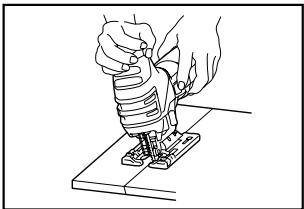
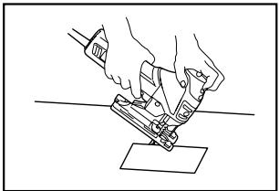
B) Plunge cutting:
natural_image
Line drawing of hands using a tool to cut or mark a piece of paper (no text or symbols present)
008037
You need not bore a starting hole or make a lead-in cut if you carefully do as follows.
(1) Tilt the tool up on the front edge of the base with the blade point positioned just above the workpiece surface.
(2) Apply pressure to the tool so that the front edge of the base will not move when you switch on the tool and gently lower the back end of the tool slowly.
(3) As the blade pierces the workpiece, slowly lower the base of the tool down onto the workpiece surface.
(4) Complete the cut in the normal manner.
Finishing edges
natural_image
Line drawing of a hand using a sewing machine to cut or install a piece of material (no text or symbols present)
008038
To trim edges or make dimensional adjustments, run the blade lightly along the cut edges.
Always use a suitable coolant (cutting oil) when cutting metal. Failure to do so will cause significant blade wear. The underside of the workpiece can be greased instead of using a coolant.
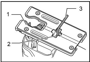
Rip fence set (optional accessory)
CAUTION:
- Always be sure that the tool is switched off and unplugged before installing or removing accessories.
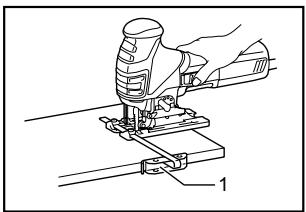
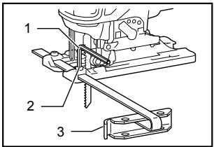
1. Straight cuts
When repeatedly cutting widths of 160 mm (6-5/16") or less, use of the rip fence will assure fast, clean, straight cuts. To install, insert the rip fence into the rectangular hole on the side of the tool base with the fence guide facing down. Slide the rip fence to the desired cutting width position, then tighten the bolt to secure it.
natural_image
Technical line drawing of a sewing machine tool (no text or symbols)
008040
1. Rip fence

008041
- Hex wrench
- Bolt
-
Fence guide
-
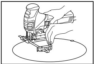
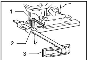
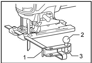
Circular cuts
natural_image
Line drawing of a hand using a power tool to press or install a component (no text or symbols present)
008042

008043
- Fence guide
- Threaded knob
- Circular guide pin
When cutting circles or arcs of 170 mm (6-11/16") or less in radius, install the rip fence as follows.
Insert the rip fence into the rectangular hole on the side of the base with the fence guide facing up. Insert the circular guide pin through either of the two holes on the fence guide. Screw the threaded knob onto the pin to secure the pin.
Now slide the rip fence to the desired cutting radius, and tighten the bolt to secure it in place. Then move the base all the way forward.
NOTE:
• Always use blades No. B-17, B-18, B-26 or B-27 when cutting circles or arcs.
MAINTENANCE
⚠️CAUTION:
• Always be sure that the tool is switched off and unplugged before attempting to perform inspection or maintenance.
To maintain product SAFETY and RELIABILITY, repairs, carbon brush inspection and replacement, any other maintenance or adjustment should be performed by Makita Authorized or Factory Service Centers, always using Makita replacement parts.
ACCESSORIES
⚠️CAUTION:
- These accessories or attachments are recommended for use with your Makita tool specified in this manual. The use of any other accessories or attachments might present a risk of injury to persons. Only use accessory or attachment for its stated purpose.
If you need any assistance for more details regarding these accessories, ask your local Makita Service Center.
- Jig saw blades
- Hex wrench
- Rip fence (guide rule) set
• Anti-splintering device
- Dust nozzle
- Cover plate
• Hose (For vacuum cleaner)
MAKITA LIMITED ONE YEAR WARRANTY Warranty Policy
Every Makita tool is thoroughly inspected and tested before leaving the factory. It is warranted to be free of defects from workmanship and materials for the period of ONE YEAR from the date of original purchase. Should any trouble develop during this one year period, return the COMPLETE tool, freight prepaid, to one of Makita's Factory or Authorized Service Centers. If inspection shows the trouble is caused by defective workmanship or material, Makita will repair (or at our option, replace) without charge.
This Warranty does not apply where:
• repairs have been made or attempted by others:
- repairs are required because of normal wear and tear:
- the tool has been abused, misused or improperly maintained:
• alterations have been made to the tool.
IN NO EVENT SHALL MAKITA BE LIABLE FOR ANY INDIRECT, INCIDENTAL OR CONSEQUENTIAL DAMAGES FROM THE SALE OR USE OF THE PRODUCT. THIS DISCLAIMER APPLIES BOTH DURING AND AFTER THE TERM OF THIS WARRANTY.
MAKITA DISCLAIMS LIABILITY FOR ANY IMPLIED WARRANTIES, INCLUDING IMPLIED WARRANTIES OF "MERCHANTABILITY" AND "FITNESS FOR A SPECIFIC PURPOSE," AFTER THE ONE YEAR TERM OF THIS WARRANTY.
This Warranty gives you specific legal rights, and you may also have other rights which vary from state to state. Some states do not allow the exclusion or limitation of incidental or consequential damages, so the above limitation or exclusion may not apply to you. Some states do not allow limitation on how long an implied warranty lasts, so the above limitation may not apply to you.
EN0006-1
FRANÇAIS
SPÉCIFICATIONS
natural_image
Technical line drawing of a sewing machine with no visible text or symbols
natural_image
Technical line drawing of a mechanical assembly with labeled parts (no text or symbols present)
008031
008032
008007
008008
008009
008033
- Base
- Clé hexagonale
008028
- Base
- Dispositif anti-fente
008027
- Plaque de recouvrement
- Base
natural_image
Technical line drawing of a mechanical assembly with a downward arrow indicating motion (no text or symbols)
001922
008039
008034
natural_image
Line drawing of hands operating a sewing machine on a cutting board (no text or symbols)
008035
ATTENTION:
008013
- Base
- Boulon
- Clé hexagonale
008014
- Graduation
- Fente en biseau
- Base
- Carter
d'engrenage
- Encoche en V
- Boulon
008015
- Base
- Boulon
- Clé hexagonale
natural_image
Line drawing of a hand using a sewing machine to cut fabric or paper onto a piece, with no visible text or symbols.
natural_image
Line drawing of hands using a power tool to cut or mark a flat surface (no text or symbols)
008037
natural_image
Line drawing of a hand using a power tool to cut or install a piece of material (no text or symbols present)
008038
natural_image
Technical line drawing of a hand operating a drill bit on a workbench (no text or symbols)
008040
- Garde parallèle
008041
natural_image
Line drawing of a hand using a power tool to press or install a component (no text or symbols present)
008042

008043
natural_image
Technical line drawing of a sewing machine with base mount (no text or symbols)
natural_image
Technical line drawing of a mechanical assembly with labeled parts (no text or symbols present)
008031
- Gatillo del interruptor
⚠️PRECAUCIÓN:
natural_image
Mechanical assembly diagram showing a valve mechanism inside a vehicle (no text or labels)
008007
008008
008009
- Hoja de sierra caladora
NOTA:
008033
- Base
- Llave hexagonal
008028
008027
natural_image
Technical line drawing of a mechanical assembly with a lever and base component (no text or symbols)
001922
008039
- Boquilla para polvo
- Manguera para aspirador
⚠️PRECAUCIÓN:
008034
- Línea de corte
- Base
natural_image
Line drawing of a hand using a sewing machine to press or install a piece of material (no text or symbols present)
008035
⚠️PRECAUCIÓN:
008013
- Base
- Tornillo
- Llave hexagonal
008014
008015
- Base
- Tornillo
- Llave hexagonal
natural_image
Line drawing of a hand using a sprocket to cut a piece of paper with small circular pieces nearby (no text or symbols)
008036
- Orificio de inicio
natural_image
Line drawing of hands using a sewing machine to cut or mark a piece of paper (no text or symbols present)
008037
natural_image
Line drawing of a hand using a sewing machine to press or install a piece of material (no text or symbols present)
008038
natural_image
Technical line drawing of a sewing machine tool (no text or symbols)
008040
- Tope lateral de corte
008041
- Llave hexagonal
- Tornillo
-
Guía lateral
-
Cortes circulares

natural_image
Line drawing of hands operating a sewing machine (no text or symbols)
008042
008043
- Guía lateral
- Perilla roscada
- Clavija de la guía circular
Some dust created by power sanding, sawing, grinding, drilling, and other construction activities contains chemicals known to the State of California to cause cancer, birth defects or other reproductive harm. Some examples of these chemicals are:
- lead from lead-based paints,
• crystalline silica from bricks and cement and other masonry products, and
• arsenic and chromium from chemically-treated lumber.
Your risk from these exposures varies, depending on how often you do this type of work. To reduce your exposure to these chemicals: work in a well ventilated area, and work with approved safety equipment, such as those dust masks that are specially designed to filter out microscopic particles.
< USA solamente >
ADVERTENCIA

