
4340FCT - Jigsaw MAKITA - Free user manual and instructions
Find the device manual for free 4340FCT MAKITA in PDF.

| Brand | Makita |
| Model | 4340FCT |
| Product Type | Jigsaw |
| Stroke Length | 26 mm |
| Wood Cutting Capacity | 135 mm |
| Steel Cutting Capacity | 10 mm |
| Strokes per Minute | 800 – 2,800 min⁻¹ |
| Overall Length | 239 mm |
| Net Weight | 2.4 kg |
| Power Supply | Single-phase, double insulation |
| Variable Speed | Yes, speed adjustment dial 1 to 5 |
| Orbital Cutting | Yes, 3 levels |
| Soft Start Function | Yes |
| LED Light | Yes |
| Dust Extraction Adapter | Yes (accessory) |
| Parallel Guide | Available (accessory) |
| Rip Guide | Available (accessory) |
| Cover Plate | Available (accessory) |
| Anti-Splinter Device | Available (accessory) |
| Maintenance | Regular cleaning, lubricate roller |
| Repairability | Makita Service Center |
| Safety | Double insulation, safety instructions |
Frequently Asked Questions - 4340FCT MAKITA
User questions about 4340FCT MAKITA
0 question about this device. Answer the ones you know or ask your own.
Ask a new question about this device
Download the instructions for your Jigsaw in PDF format for free! Find your manual 4340FCT - MAKITA and take your electronic device back in hand. On this page are published all the documents necessary for the use of your device. 4340FCT by MAKITA.
USER MANUAL 4340FCT MAKITA
natural_image
Line drawing of a Jigsaw power tool with visible screw base and handle (no text or symbols)
1
2
3
4
5
6
7
8
natural_image
Line drawing of a person using a power tool on a base (no text or symbols)9
10
11
12
natural_image
Line drawing of a hand using a power tool to cut a component, with no visible text or symbols13
natural_image
Line drawing of a hand using a power tool to cut a component (no text or symbols)14
natural_image
Line drawing of a hand operating a small electronic device (no text or symbols present)15
16
17
18
natural_image
Line drawing of a hand operating a power tool on a base plate, labeled with number 20 (no text or symbols beyond label)19
20
natural_image
Line drawing of a hand operating a power strip device (no text or symbols)21
22
natural_image
Line drawing of a power tool on a wooden base (no text or symbols)23
24
25
26
27
Symbols
The following show the symbols used for the tool. Be sure that you understand their meaning before use.
Symboles
Explanation of general view
| 1 | Tool opener | 12 | Bolt | 23 | Threaded knob |
| 2 | Blade clamp | 13 | Gear housing | 24 | Circular guide pin |
| 3 | Jig saw blade | 14 | V-notch | 25 | Rule bar |
| 4 | Protrusions | 15 | Bevel slot | 26 | Guide rail adapter |
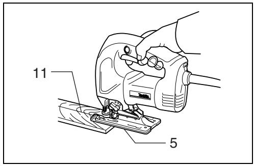
| 5 | Base | 16 | Graduations | 27 | Guide rail |
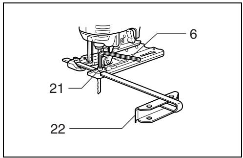
| 6 | Hex wrench | 17 | Starting hole | 28 | Screw |
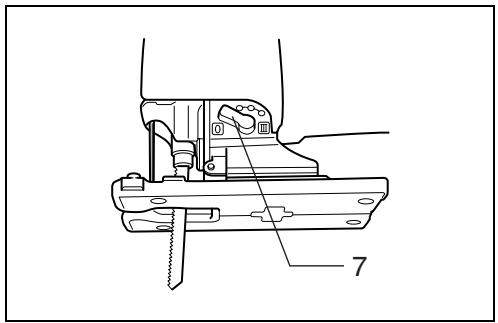
| 7 | Cutting action changing lever | 18 | Dust nozzle | 29 | Cover plate |
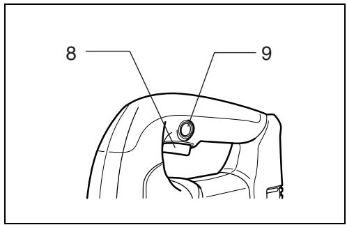
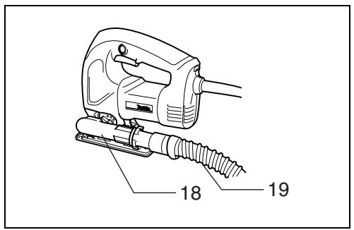
| 8 | Switch trigger | 19 | Hose for vacuum cleaner | 30 | Anti-splintering device |
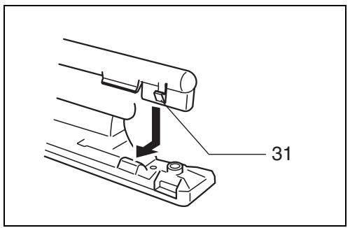
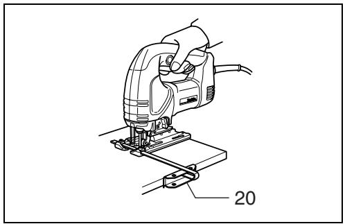
| 9 | Lock button | 20 | Rip fence | 31 | Hook |
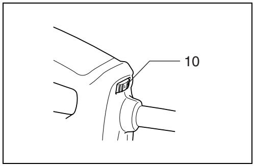
| 10 | Speed adjusting dial | 21 | Bolt | ||
| 11 | Cutting line | 22 | Fence guide |
SPECIFICATIONS
| Model | 4340T | 4340CT | 4340FCT |
| Length of stroke | 26 mm | 26 mm | 26 mm |
| Cutting capacities | |||
| Wood | 110 mm | 135 mm | 135 mm |
| Steel | 10 mm | 10 mm | 10 mm |
| Strokes per minute (min ^-1 ) | 2,800 | 800 – 2,800 | 800 – 2,800 |
| Overall length | 239 mm | 239 mm | 239 mm |
| Net weight | 2.4 kg | 2.4 kg | 2.4 kg |
- Due to our continuing program of research and development, the specifications herein are subject to change without notice.
- Note: Specifications may differ from country to country.
Intended use
The tool is intended for the sawing of wood, plastic and metal materials. As a result of the extensive accessory and saw blade program, the tool can be used for many purposes and is very well suited for curved or circular cuts.
Power supply
The tool should be connected only to a power supply of the same voltage as indicated on the nameplate, and can only be operated on single-phase AC supply.
They are double-insulated in accordance with European Standard and can, therefore, also be used from sockets without earth wire.
Safety hints
For your own safety, please refer to the enclosed safety instructions.
ADDITIONAL SAFETY RULES
ENB062-1
- Hold tool by insulated gripping surfaces when performing an operation where the cutting tools may contact hidden wiring or its own cord. Contact with a "live" wire will make exposed metal parts of the tool "live" and shock the operator.
- Avoid cutting nails. Inspect workpiece for any nails and remove them before operation.
- Do not cut hollow pipe.
- Do not cut oversize workpiece.
- Check for the proper clearance beyond the workpiece before cutting so that the blade will not strike the floor, workbench, etc.
- Hold the tool firmly.
- Make sure the blade is not contacting the workpiece before the switch is turned on.
-
Keep hands away from moving parts.
-
Do not leave the tool running. Operate the tool only when hand-held.
- Always switch off and wait for the blade to come to a complete stop before removing the blade from the workpiece.
- Do not touch the blade or the workpiece immediately after operation; they may be extremely hot and could burn your skin.
SAVE THESE INSTRUCTIONS.
OPERATING INSTRUCTIONS
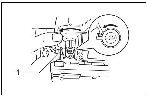
Installing or removing saw blade (Fig.1, 2 & 3)
CAUTION:
- Always be sure that the tool is switched off and unplugged before installing or removing the blade.
- Always clean out all chips or foreign matter adhering to the blade and/or blade holder. Failure to do so may cause insufficient tightening of the blade, resulting in a serious injury.
- Do not touch the blade or the workpiece immediately after operation; they may be extremely hot and could burn your skin.
- Tighten the saw blade securely. Failure to do so may cause a serious injury.
Installing saw blade
Open the tool opener to the position shown in the figure. (Fig. 1)
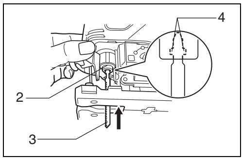
Keeping that situation, insert the saw blade into the blade clamp as far as the two protrusions of the blade can not be seen. (Fig. 2)
Return the tool opener to its original position. After installing the saw blade, always make sure that the blade is securely held in place by trying to pull it out.
CAUTION:
Do not open the tool opener excessively, or it may cause tool damage.
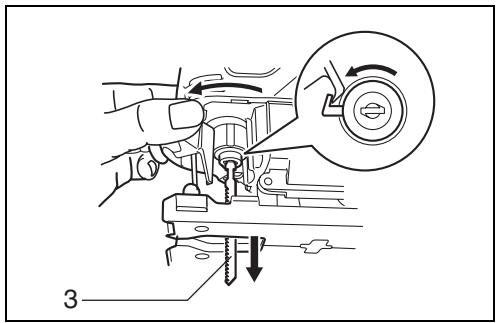
Removing saw blade
CAUTION:
When you remove the saw blade, be careful not to hurt your fingers with the top of the blade or the tips of workpiece.
Open the tool opener to the position shown in the figure. Pull the saw blade out toward the base. (Fig. 3)
NOTE:
Occasionally lubricate the roller.
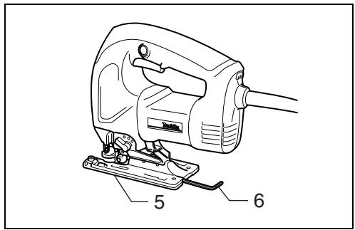
Hex wrench storage (Fig. 4)
When not in use, the hex wrench can be conveniently stored.
Selecting the cutting action (Fig. 5)
This tool can be operated with an orbital or a straight line (up and down) cutting action. The orbital cutting action thrusts the blade forward on the cutting stroke and greatly increases cutting speed.
To change the cutting action, just turn the cutting action changing lever to the desired cutting action position.
Refer to the table below to select the cutting action.
| Position | Cutting action | Applications |
| 0 | Straight line cutting action | For cutting mild steel, stainless steel and plastics.For clean cuts in wood and plywood. |
| I | Small orbit cutting action | For cutting mild steel, aluminum and hard wood. |
| II | Medium orbit cutting action | For cutting wood and plywood.For fast cutting in aluminum and mild steel. |
| III | Large orbit cutting action | For fast cutting in wood and plywood. |
Switch action (Fig. 6)
CAUTION:
Before plugging in the tool, always check to see that the switch trigger actuates properly and returns to the "OFF" position when released.
To start the tool, simply pull the switch trigger. Release the switch trigger to stop. For continuous operation, pull the switch trigger and then push in the lock button. To stop the tool from the locked position, pull the switch trigger fully, then release it.
Speed adjusting dial (Fig. 7)
The tool speed can be infinitely adjusted between 800 and 2,800 strokes per minute by turning the adjusting dial. Higher speed is obtained when the dial is turned in the direction of number 5; lower speed is obtained when it is turned in the direction of number 1. Refer to the table below to select the proper speed for the workpiece to be cut. However, the appropriate speed may differ with the type or thickness of the workpiece. In general, higher speeds will allow you to cut workpieces faster but the service life of the blade will be reduced.
| Workpiece to be cut | Number on adjusting dial |
| Wood | 4 – 5 |
| Mild steel | 3 – 5 |
| Stainless steel | 3 – 4 |
| Aluminum | 3 – 5 |
| Plastics | 1 – 4 |
CAUTION:
The speed adjusting dial can be turned only as far as 5 and back to 1. Do not force it past 5 or 1, or the speed adjusting function may no longer work.
For 4340CT, 4340FCT
The tools equipped with electronic function are easy to operate because of the following features.
Constant speed control
Electronic speed control for obtaining constant speed. Possible to get fine finish, because the rotating speed is kept constant even under load condition.
Soft start feature
Safety and soft start because of suppressed starting shock.
Lighting up the lamps (For 4340FCT only)
CAUTION:
Do not look in the light or see the source of light directly.
To turn on the lamp, pull the trigger. Release the trigger to turn it off.
NOTE:
Use a dry cloth to wipe the dirt off the lens of lamp. Be careful not to scratch the lens of lamp, or it may lower the illumination.
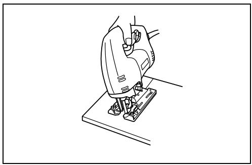
Operation (Fig. 8)
CAUTION:
Always hold the tool base flush with the workpiece. Failure to do so may cause blade breakage, resulting in a serious injury.
Turn the tool on and wait until the blade attains full speed. Then rest the tool base flat on the workpiece and gently move the tool forward along the previously marked cutting line. When cutting curves, advance the tool very slowly.
Bevel cutting
CAUTION:
Always be sure that the tool is switched off and unplugged before tilting the tool base.
With the tool base tilted, you can make bevel cuts at any angle between 0^ and 45^ (left or right). (Fig. 9)
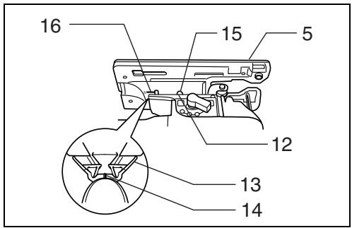
Loosen the bolt on the back of the base with the hex wrench. Move the base so that the bolt is positioned in the center of the bevel slot in the base. (Fig. 10 & 11)
Tilt the base until the desired bevel angle is obtained. The V-notch of the gear housing indicates the bevel angle by graduations. Then tighten the bolt firmly to secure the base. (Fig. 11)
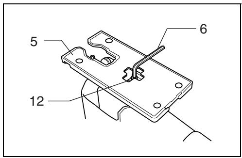
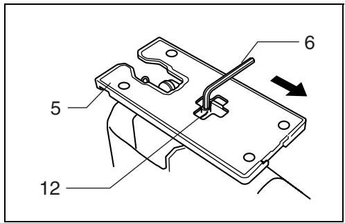
Front flush cuts (Fig. 12)
Loosen the bolt on the back of the tool base with the hex wrench, then move the tool base all the way back. Then tighten the bolt to secure the tool base.
Cutouts
Cutouts can be made with either of two methods A or B.
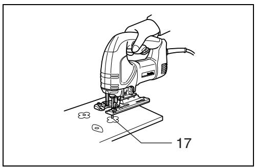
A) Boring a starting hole: For internal cutouts without a lead-in cut from an edge, pre-drill a starting hole 12 mm or more in diameter. Insert the blade into this hole to start your cut. (Fig. 13)
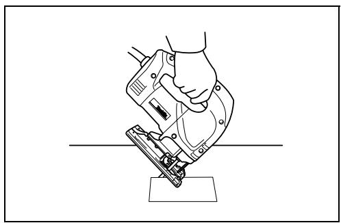
B) Plunge cutting: You need not bore a starting hole or make a lead-in cut if you carefully do as follows.
- Tilt the tool up on the front edge of the base, with the blade point positioned just above the workpiece surface. (Fig. 14)
- Apply pressure to the tool so that the front edge of the base will not move when you switch on the tool and gently lower the back end of the tool slowly.
- As the blade pierces the workpiece, slowly lower the base of the tool down onto the workpiece surface.
- Complete the cut in the normal manner.
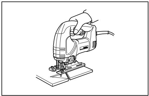
Finishing edges (Fig. 15)
To trim edges or make dimensional adjustments, run the blade lightly along the cut edges.
Metal cutting
Always use a suitable coolant (cutting oil) when cutting metal. Failure to do so will cause significant blade wear. The underside of the workpiece can be greased instead of using a coolant.
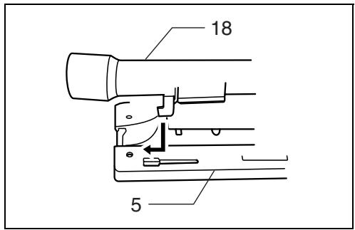
Dust extraction
The dust nozzle (accessory) is recommended to perform clean cutting operations. To attach the dust nozzle on the tool, insert the hook of dust nozzle into the hole in the base. (Fig. 16 & 17)
The dust nozzle can be installed on either left or right side of the base. Then connect a Makita vacuum cleaner to the dust nozzle. To remove the dust nozzle, follow the installing procedure in reverse. (Fig. 18)
CAUTION:
If you try to remove the dust nozzle forcibly, the hook of the dust nozzle can be diminished and removed unintentionally during operation.
Rip fence set (accessory)
CAUTION:
Always be sure that the tool is switched off and unplugged before installing or removing accessories.
1) Straight cuts (Fig. 19 & 20)
When repeatedly cutting widths of 160 mm or less, use of the rip fence will assure fast, clean, straight cuts. To install, insert the rip fence into the rectangular hole on the side of the tool base with the fence guide facing down. Slide the rip fence to the desired cutting width position, then tighten the bolt to secure it.
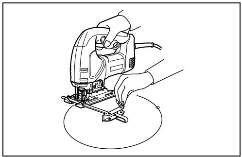
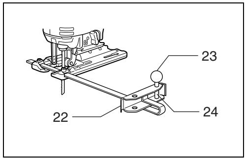
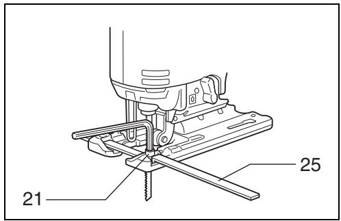
2) Circular cuts (Fig. 21 & 22)
When cutting circles or arcs of 170 mm or less in radius, install the rip fence as follows.
Insert the rip fence into the rectangular hole on the side of the tool base with the fence guide facing up. Insert the circular guide pin through either of the two holes on the fence guide. Screw the threaded knob onto the pin to secure the pin.
Now slide the rip fence to the desired cutting radius, and tighten the bolt to secure it in place. Then move the tool base all the way forward.
NOTE:
Always use blades No. B-17, B-18, B-26 or B-27 when cutting circles or arcs.
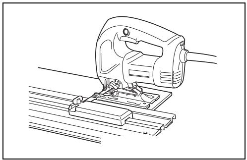
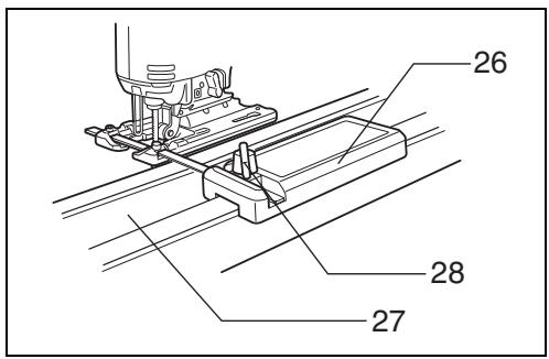
Guide rail adapter set (accessory)
When cutting parallel and uniform width or cutting straight, the use of the guide rail and the guide rail adapter will assure the production of fast and clean cuts.
(Fig. 23)
To install the guide rail adapter, insert the rule bar into the square hole of the base as far as it goes. Secure the bolt with the hex wrench securely. (Fig. 24)
Install the guide rail adapter on the rail of the guide rail. Insert the rule bar into the square hole of the guide rail adapter. Put the base to the side of the guide rail, and secure the bolt securely. (Fig. 25)
CAUTION:
Always use blades No. B-8, B-13, B-16, B-17 or 58 when using the guide rail and the guide rail adapter.
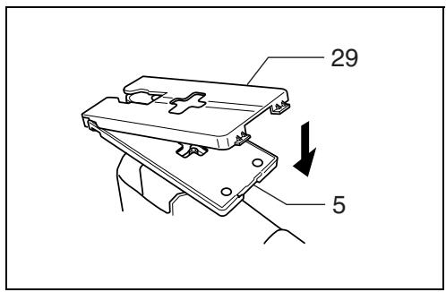
Cover plate (Fig. 26)
Use the cover plate when cutting decorative veneers, plastics, etc. It protects sensitive or delicate surfaces from damage. Fit it on the back of the tool base.
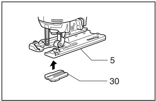
Anti-splintering device (Fig. 27)
For splinter-free cuts, the anti-splintering device can be used. To install the anti-splintering device, move the tool base all the way forward and fit it from the back of tool base. When you use the cover plate, install the anti-splintering device onto the cover plate.
CAUTION:
The anti-splintering device cannot be used when making bevel cuts.
MAINTENANCE
CAUTION:
Always be sure that the tool is switched off and unplugged before carrying out any work on the tool.
To maintain product safety and reliability, repairs, maintenance or adjustment should be carried out by a Makita Authorized Service Center.
Descriptif
These accessories or attachments are recommended for use with your Makita tool specified in this manual. The use of any other accessories or attachments might present a risk of injury to persons. The accessories or attachments should be used only in the proper and intended manner.
F ACCESSOIRES
ATTENTION :
EC-DECLARATION OF CONFORMITY
We declare under our sole responsibility that this product is in compliance with the following standards or standardized documents,
HD400, EN50144, EN55014, EN61000
in accordance with Council Directives, 73/23/EEC, 89/336/EEC and 98/37/EC.
FRANÇAISE
DÉCLARATION DE CONFORMITÉ CE
HD400, EN50144, EN55014, EN61000.
ITALIANO
Michigan Drive, Tongwell, Milton Keynes, Bucks MK15 8JD, ENGLAND
PORTUGUÊS
EU-DEKLARATION OM KONFORMITET
HD400, EN50144, EN55014, EN61000.
Yasuhiko Kanzaki CE 2001

Director
Direktør
Direktör
Direktor
Johtaja
Διευθυντής
Müdür
MAKITA INTERNATIONAL EUROPE LTD.
Michigan Drive, Tongwell, Milton Keynes,
Bucks MK15 8JD, ENGLAND
ENGLISH
Noise and Vibration
The typical A-weighted sound pressure level is 83 dB (A).
The noise level under working may exceed 85 dB (A).
- Wear ear protection. -
The typical weighted root mean square acceleration value is 8 m/s^2 .