
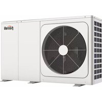
Fahu - Air Handling Unit FERROLI - Free user manual and instructions
Find the device manual for free Fahu FERROLI in PDF.


| Product Type | Air Handling Unit |
| Brand | Ferroli |
| Model | Fahu |
| Category | Unidad de Tratamiento de Aire |
| Dimensions (W x H x D) | 800 x 600 x 400 mm |
| Weight | 50 kg |
| Power Supply | 230V, 50Hz, single phase |
| Max Airflow | 2000 m³/h |
| Functions | Heating, Cooling, Ventilation, Filtration |
| Filter Class | G4 (pre-filter) |
| Noise Level | 60 dB(A) at max speed |
| Insulation | Thermal and acoustic insulation |
| Control Type | Electronic controller with remote option |
| Installation | Indoor, vertical or horizontal |
| Maintenance | Filter cleaning every 3 months, annual inspection |
| Safety Features | Overheat protection, fan delay, emergency stop |
| Spare Parts Availability | Filters, motors, sensors, controllers |
| Reparability | Modular design, easy access to components |
| Certifications | CE, RoHS |
Frequently Asked Questions - Fahu FERROLI
User questions about Fahu FERROLI
0 question about this device. Answer the ones you know or ask your own.
Ask a new question about this device
Download the instructions for your Air Handling Unit in PDF format for free! Find your manual Fahu - FERROLI and take your electronic device back in hand. On this page are published all the documents necessary for the use of your device. Fahu by FERROLI.
USER MANUAL Fahu FERROLI
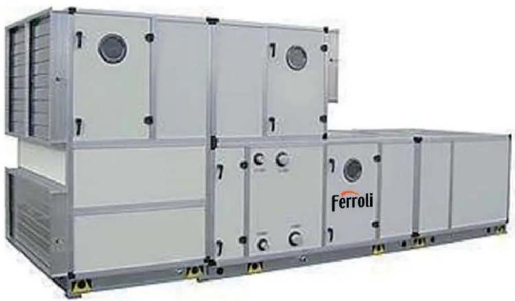
CENTRAL STATION AIR HANDLING UNITS
natural_image
Exterior view of a large industrial container unit with visible branding and control panels (no readable text beyond brand name)CE
ITA - MANUALE INSTALLAZIONE E MANUTENZIONE EN - INSTALLATION AND MAINTENANCE MANUAL
INDICE GENERALE
INTRODUZIONE pag. 3
natural_image
Isometric line drawing of a rectangular enclosure or cabinet with mounting holes and a label 'A' (no text or symbols on the diagram itself)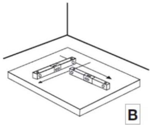
natural_image
Isometric diagram of two rectangular blocks mounted on a base plate, with directional arrows indicating movement (no text or symbols)
natural_image
Isometric line drawing of a rectangular industrial or structural component mounted on a rail base, with no visible text or symbols.
natural_image
Isometric line drawing of a rectangular enclosure with vertical supports and mounting holes (no text or symbols)11
natural_image
Isometric line drawing of a rectangular industrial or structural component with mounting base and internal compartments (no text or symbols)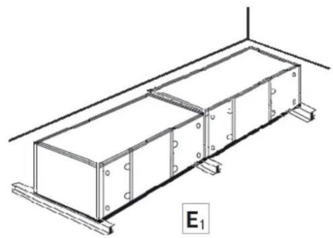
natural_image
Technical line drawing of a rectangular industrial or electrical enclosure with mounting brackets and structural supports (no text or symbols)
natural_image
Technical line drawing of a structural frame with supports and mounting base (no text or symbols)
natural_image
Isometric line drawing of a truss structure with triangular spans and support beams (no text or symbols)
Fig. 7
GENERAL DISPOSITIONS 4
RESIDUAL RISKS 5
- UNIT IDENTIFICATION 6
- CHECK AT RECEIVAL 7
-
TRANSPORTATION AND HANDLING 8
-
INSTALLATION 9
4.1. Preliminary notice 9
4.2. Service area requirements 12
4.3. Sections coupling and bolting 12
4.4. Coil connections 14
4.5. Hydronic connections 16
4.6 Connection to water supply systems for humidification 16
4.7. Air connections 17
4.8. Electrical connections 17
-
UNIT START UP 23
5.1. Safety systems 23
5.2. Electric motors, fans and drives 23
5.3. Air filters 24
5.4. Humidifier sections and pumps 24
5.5.Coils 25
5.6. Dampers 25 -
MAINTENANCE 26
6.1. Safety systems 26
6.2. Electric motors, fans and drives 26
6.3. Air filters 28
6.4. Humidifier section and pumps 29
6.5.Coils 29
6.6. Dampers 30
6.7. Unit shut down precautions 30
6.8. Summary schedule for periodical maintenance 31
6.9. Trouble shooting 32
6.10. Unit record manual 34 -
REPLACEMENT PARTS 35
7.1. Unit identification 35
7.2. Identification of the part to be replaced 35
7.3. Replacement parts ordering 35 -
DISMANTLEMENT AND DISPOSAL OF MATERIALS 35
8.1 Unit disconnection 35 -
APPROXIMATE PLACEMENT OF SIGNAL STICKERS AND IDENTIFICATIONATE 37
INTRODUCTION
Air handling units, central station type, should be installed and operated in accordance with requirements listed in this manual. Observing these simple instructions carefully is a preliminary precaution in order to:
- totally avoid or substantially decrease number of unit shutdowns for unforeseen breakdowns;
- increase component efficiency and consequently conserve energy;
- increase component and unit life;
- decrease maintenance need.
This unit has been designed in accordance with EU Directives 2006/42/CE, 2014/35/EU, 2014/30/EU as applicable, and complies with "essential criteria for safety and health protection" therein specified.
Unit is therefore equipped with appropriate devices fully described in the technical literature supplied with the unit. Installer should carefully connect and activate all safety components provided on the unit and check for their operation.
The plant or system, where this unit is assembled in, must also comply with the above mentioned Directives.
End users, or any plant operators, should periodically check for proper operation and efficiency of safety devices. Non activating or removing or impeding operation of active safety devices, as well as removal of passive safety equipment, will cause immediate loss liability with regard to any accidents or damages, direct or indirect, to persons or property, due manufactured unit.
The Unit manual, provided with the unit, is completed by a "Technical Form" reporting all essential unit construction and operational data together with relevant drawings.
Trasportation and handling, as well as operation of unit, should be carried out in accordance with instructions given in the present notes and following pages, as well as technical literature supplied with the unit.
Unit maintenance should be made by trained and qualified service personnel, who must follow all safety codes and other precautions that may apply; wear safety glasses and work gloves.
Guarantee is limited by conditions and terms described in the "CERTIFICATE" supplied with the unit and bearing unit type and serial number.
This unit is not suitable for operation in explosive atmosphere
GENERAL DISPOSITIONS
The present manual is realized to allow the correct unit's installation, the start up and maintenance. It is consequently fundamental:
– to read the following instructions carefully
- only qualified staff (who owns the requirements provided by the law) can install, test and handle the unit
– observe local safety regulations in force at the moment of installation
- check that electric net's characteristics comply with the data indicated on the identification plate
– the manual and unit's electric schemes must be conserved with particular care for any further consultation
- packing materials as plastic films, expanded polystyrene, nails etc. must be kept out of children's reach because they are potentially dangerous. They must be also correctly recycled according to lacal regulations in force
- the unit must be used only for the scopes it is designed to (Ref. technical schedule)
– Any use which is different from those specified does not bind the Manufacturer to answer for it
- Disconnect the machine in case of damages or bad working
SOUND LEVELS
See technical schedule
DIMENSIONS
See general draws attached to technical schedule
SAFETY INTEGRATION PRINCIPLES
The machine is designed and built to avoid any risk for health and people.
Many project's solutions have been carried out to avoid (where is possible) any kind of danger. Where there is no possibility to completely prevent or avoid dangers, please respect behavioural disposition indicated in the paragraph “RESIDUAL RISKS”.
RESIDUAL RISKS
This definition includes all those dangers which can not be completely eliminated during the planning phase or through protection devices; it also includes all potential risks which are not evident.
SECURITY INSTRUCTIONS CAUTION!
ANY OPERATION WHICH CAN PRODUCE DANGEROUS SITUATIONS IS INDICATED IN THIS MANUAL. IT ALSO CONTAINS PRECAUTIONARY MEASURES FOR ANY SPECIFIC CASE.
– All the units are provided with pictograms with danger warnings
- All the units are safe, and it is forbidden to tamper with the machines or to remove security protections
- To operate in total secure conditions it is helpful to have a technical preparation, and it is important to respect the proceedings illustrated in this manual and eventual signalling affixed in critical places of the unit.
- The following dispositions must be respected during the installation, the start up, the use and maintenance of the unit.
PROHIBITIONS!
- Do not start up the unit before its electric components are wired to the building's electric plant
- Do not start up the unit before the fan outlet is wired to a duct or protected with an accident prevention grid
- Do not use the unit as a support for another machine
- Do not use the unit as a platform
- Do not use the unit as an equipment's storehouse
- Do not open inspection doors while the fan is working, especially near pressure sections
- Do not leave inspection doors half closed, but check that handles and knobs are completely closed
- Do not expose oneself to ultraviolet lamp's light, which are situated in those sections where germicidal lamps are used
OBLIGATIONS!
- Wear individual security devices before working with the unit
Before unit's start up check that all electrical devices are off. Especially, before opening inspection doors, check that the fan is switched off and that no one can start it up without the knowledge of the technicist who is operating on the machine - Always reassemble the protection grid of the fan section before the start up
CAUTION!
– Pay attention during lifting the machine, because its barycentre can be very unbalanced
– Pay attention to lifting cables/hooks blocking
– Pay attention to edges inside the unit
– Pay attention to roof edges outside the unit
– Pay attention to possible burns that heat coils can cause
— Pay attention to possible burns that humidification system can cause
— Pay attention to servo-controlled dampers which could suddenly close
1. UNIT IDENTIFICATION
A metal name plate, usually mounted on the external surface of the inspection panel of the unit fan section, bears unit identification data and main technical characteristics. Fig. 1 shows the name plate and data included.
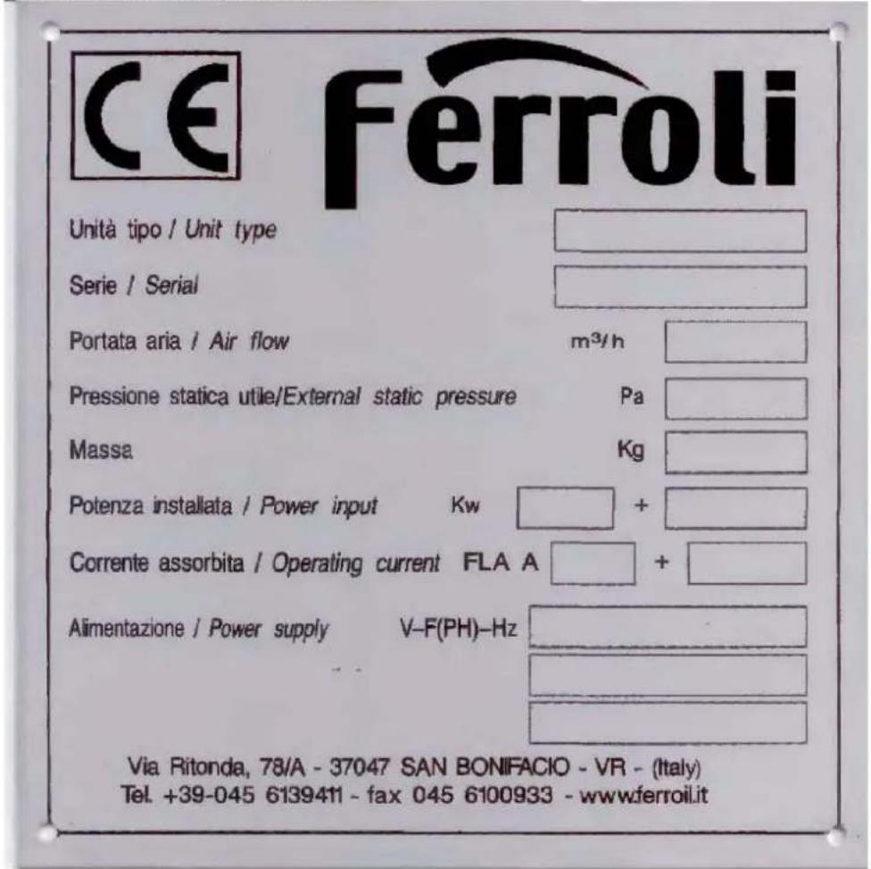
1 - CE Mark.
2 - Unit type and size.
3 - Serial number.
4 - Air flow, at standard conditions and external available static pressure.
5 - Design external available static pressure.
6- Unit's total weight in Kg
7 - Nominal power input, inductive plus resistive.
8 - FLA, full load current according to power input type.
9 - Main supply characteristics, up to three different data for electric components with different supply characteristics.
The "Technical Form" provided with the unit bears all other technical details.
When corresponding, unit type and serial number (point 2 and 3) must always be indicated.
INSTRUCTIONS FOR WORKER'S SAFETY
- All the operations (discharge, assembly, moving etc.) must be effected after reading the following instructions. It is also important to respect Safety Directive's prescriptions and individual safety devices.
- Installation and machine's start up must be effected by a qualified staff.
2. CHECK AT RECEIVAL
Air handling units are shipped without packing and, frequently, devided into different modular sections to be assembled on site.
It is recommended to check that sections are devided in the same way as indicated on unit assembly drawings and components are free from damages due to transportation. Particularly it should be carefully checked that:
- fan-motor group rotates freely;
- antivibration isolators are not damaged;
- coil fins and threaded pipes are not damaged;
- dampers move freely;
- filters are correctly assembled and not damaged;
- external panels have no scratches or dents;
- no foreign matters are in the unit sections and their internal wall are clean.
Some types of filter cells, e.g. the absolute, bag or activated carbon types, can be shipped in a separate packing. Any damages or lack of material should be immediately reported to the shipping agent and should be informed accordingly.
Warning! In case unit sections are stored outdoors before unit assembly, they must be adequately protected against possible damages due to rain or foreign matters or dirt.
3. TRASPORTATION AND HANDLING
Each unit section or single piece unit is provided with appropriate lifting points (lifting lugs or perimeter holes for lifting bars) clearly identified in the structural base.
Lifting procedure to be followed in order to avoid any damages to side panels is schematically shown on Fig. 2.
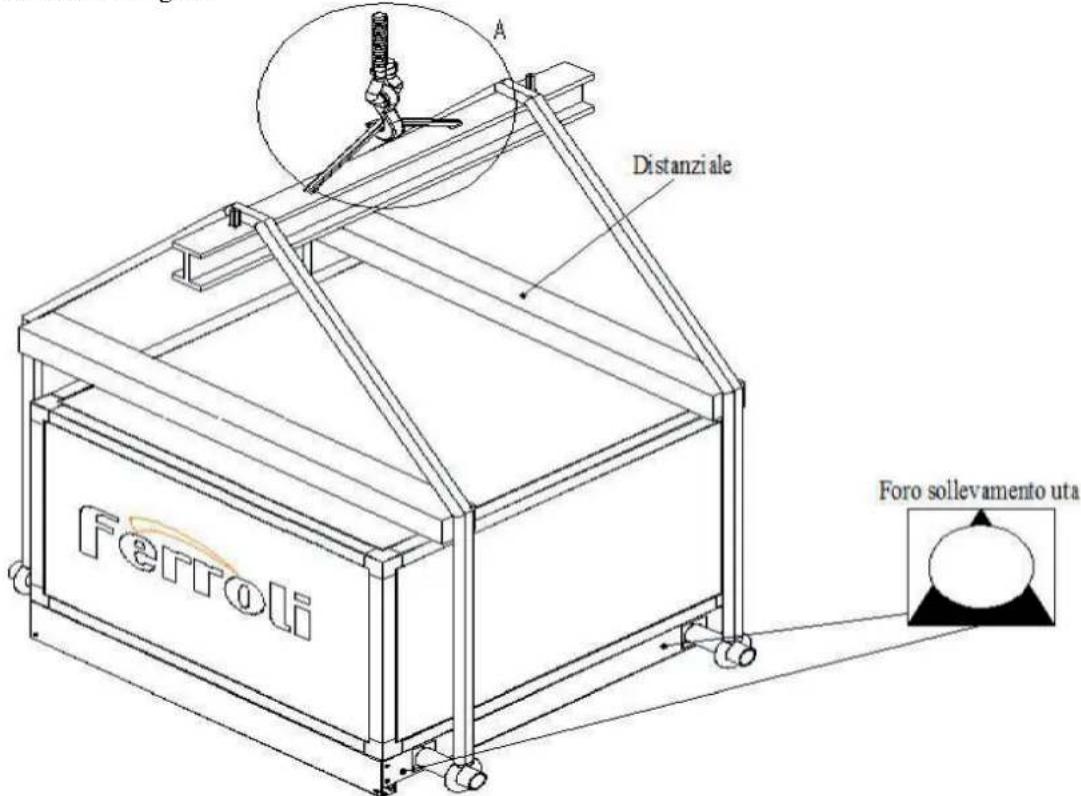
Unit sections should be handled separately, before any assembly or coupling is made. After sections are assembled, it is not possible to move the whole resulting unit..
Weight of each section or unit module, as well as the unit total weight, are shown in the technical literature supplied with the unit.
4. INSTALLATION
4.1. Preliminary notice
The unit must be placed in a suitable placement that can be built in a technical room or outside in room machinery or in outdoor location depending on the equipment provided.
The installation placement of the unit must meet the following minimum requirements:
- The floor or structure where the machine is to be placed must be adequate to support the mass of unit considering also the weight of the water machine contained in the batteries and any existing basins;
- The installation location must minimize the risk of earthquake;
- The installation location must minimize the risks in case of strong winds;
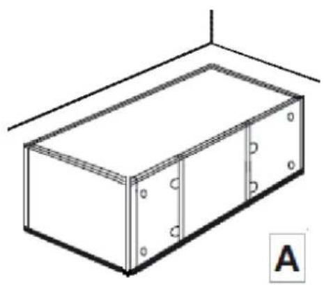
- The positioning plate of the machine can be obtained:
- directly on the floor (see A)
- on a concrete pedestal (section B)
- on metal profile pedestals (C)
- on a metal frame (Fig. D)
In any case, the following minimum requirements must be met:
- Floor or pedestals must have the characteristics to withstand the mass of the machine in compliance with the required safety limits;
- The contact surface with the lower frame of the machine must be sufficiently smooth and durable in relation to the mass of the machine;
- The floor or pedestal must allow the siphons to be fitted on the drain lines;
- The horizontal plane of the support plate must be checked and any corrections can be obtained using metal thicknesses.
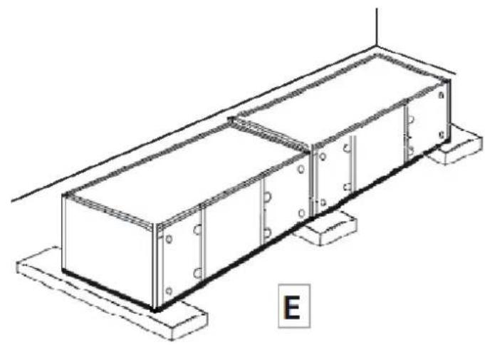
- Particular precautions must be taken in the case of machines provided in sections and / or large dimensions if it is not available a positioning placement not made by a single and continuous surface:
- as well as at the ends of the machine, support points should be provided at any intermediate support points and junctions between the individual sections (can be seen from the overall design of the machine and / or checked by our Technical Office) (dis E (concrete) - E1 (base in steel profiles));
- in the case of climbing, the individual supporting points must be made in such a way as to withstand the corresponding mass of the machine in view of the height and the respect of the seismic risk of safety
(F (concrete) - F1 (base in steel profiles));
- the surface of the support points must have a suitable width to permit positioning / approaching and assembling of the individual sections during the installation phase (see G);
natural_image
Isometric line drawing of a rectangular cabinet or enclosure with mounting holes and a label 'A' (no text or symbols on the diagram itself)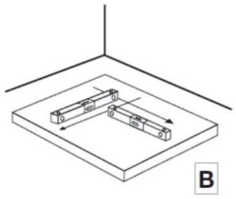
natural_image
Isometric diagram of two rectangular blocks mounted on a base plate, with directional arrows indicating movement (no text or symbols)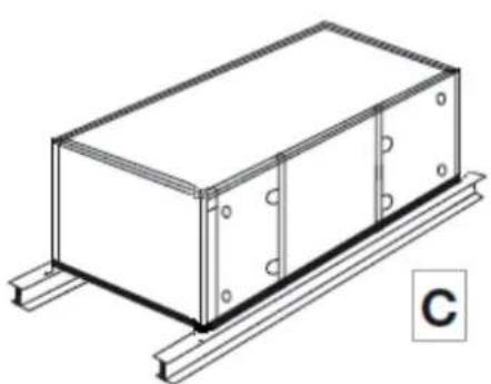
natural_image
Isometric line drawing of a rectangular industrial or electrical enclosure with mounting flanges and a base, labeled 'C' (no text or symbols on the diagram itself)
natural_image
Isometric line drawing of a rectangular enclosure with vertical posts and mounting brackets (no text or symbols)
natural_image
Isometric line drawing of a rectangular industrial or structural component with mounting base and labeled point E (no text or symbols on the diagram itself)
natural_image
Isometric line drawing of a rectangular industrial or structural component with mounting brackets and bolts, labeled E₁ (no text or symbols on the diagram itself)
natural_image
Isometric line drawing of a rectangular structural frame with supports and mounting base, labeled 'F' (no text or symbols on the diagram itself)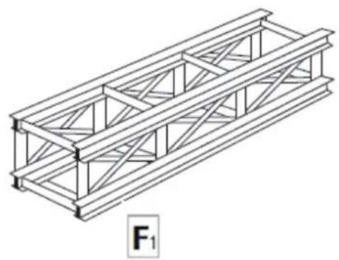
natural_image
Isometric line drawing of a truss structure with triangular spans, labeled F₁ (no text or symbols on the diagram itself)
4.2. Service area requirements
Area chooses for unit assembly must allow sufficient clearance space, around and on top of unit, for unit installation and further ordinary and extraordinary maintenance operations.
Particularly important is the service area on the inspection and connection side, in order to allow panels to open completely and coils to slide out completely for extraordinary maintenance.
Fig. 3 shows minimum clearances requested.

Fig 3
4.3. Section coupling and bolting
For unit delivered in separate sections, it is necessary to proceed to the total assembly on site, according to the overall drawings provided with the unit.
1) Apply supplied self adhesive gasket along the perimetrical face of one of the sections to be coupled.
2) Position first the heaviest section, then set beside the second one and embed it in the provided corner mortises.
3) Bolt sections together by means of holes provided in the profiles and using M8 bolts supplied with the unit. Fasten gradually and alternatively along the full perimeter (fastening couple 8-12 Nm / 0,8-1,2 kgm) until gasket between profiles is fully and uniformly pressed (see Fig. 4).
Assembly of union bolts is carried out through inspection panels, or by disassembling side panels adjacent to union profiles; as side panels are secured on to profiles by self-threading screws, highest care is required for re-assembly the same, in order not to break panel seal gasket and not to dent panel surfaces.
For small size units, assembly is made by means of four M8 bolts in the structural sheet metal base with interposing seal gasket.
4) Apply the sealing cord, supplied with unit, on the two sides and on top of the union perimeter. No resilient material or antivibration isolators should be provided between unit and supporting surface (floor) as all fan-motor groups are mounted on vibration isolators.
Fig. 4

4.4. Coil connections
4.4.1. Water coils
The following requirements for water connections are also applicable for coils with other fluid, such as glicole solutions, diathermal oil, etc. The following minimal requirements are recommended for any type of installations.
a) Provide adequate supports for external circuit and thermal expansion joints with vibration ion isolators; avoid to load coil connections.
b) Position water pipes and water circuit devices not to impede coil slide out, inspection panel openings and access to any unit sections.
c) Avoid damages to coil connection solderings by fastening mechanical connections with care without applying any torsions to the same.
Coil performance is normally rated for counter-flow circuit arrangement, consequently coils are provided with water inlet at the bottom and downstream air flow, outlet at the top and upstream air flow. This rule is ensured by following the applied plates indicating "Water in" and "Water out". Furthermore, water circuit should be provided with:
1) water drain to be positioned at the unit lowest point;
2) vent valve at the circuit highest point to allow easy replenishment;
3) shut-off valves, on water inlet and outlet, to allow coil disassembly for extraordinary maintenance;
4) for hot water coils, water pump electric interlock with the fan cycling device or circuit bypass, to avoid damages resulting from overheated stagnating air, during fan shutdown periods.
Installer must obviously guarantee the requested value of water flow.
4.4.2. Steam coils
For steam coils, follow same instructions given for water coils at points a), b), and c) of 4.4.1., paying attention to "Steam inlet" and "Steam outlet" plates. When realizing the steam circuit, installer should also take into consideration that:
1) steam coils are mounted in the section with an appropriate slope toward the outlet connection, this in order to facilitate a natural drainage of condensate;
2) shut-off valves must be installed at steam inlet and outlet, to allow easy disassembly of coil, if necessary;
3) condensate should never build up inside coils headers or supply and discharge pipes; adequate slope of minimum 2% toward the boiler should be provided for this purpose, in order to avoid water hammer at steam jet supply;
4) condensate from upstream pipes should never flow through the coil; for this purpose a condensate drain valve should be provided at coil inlet, to be connected to the return pipe to boiler;
5) condensate in the coil should be discharged through a condensate drain valve positioned downstream coil;
6) in case a steam regulating valve of "on-off" type is installed and the air system can intake air at
0°C or less, it is recommended to provide a steam pressure not less than 0.4 kg/cm2, in order to prevent coil from freezing up;
7) similarly to water coils, it is recommended to shut off steam supply when fan stops, in order to avoid overheated air from stagnating inside unit, this can damage motors and bearings and impair honeycomb packages.
4.4.3. Direct expansion coils
Instructions given at points a) and b) of 4.4.1. for water coils should be followed also in this case, bearing in mind that the best coil performance is always obtained with the counter-flow
arrangement. In this case coil supply is evidently the one provided with the distribution header where the liquid line must be connected.
The refrigerant circuit must be made in accordance to the best state-of-the-art practice; in any case, the following recommendations are to be followed:
1) coil is supplied with a holding charge of refrigerant or dehydrated nitrogen;
2) only refrigeration copper tubes should be used, tubes must be thoroughly cleaned, dehydrated and sealed until their use;
3) coil distributor should be cut only immediately before proceeding to brazing, which must be carried out in dehydrated nitrogen atmosphere which must be forced inside tube to prevent undesired oxidation;
4) same criteria must be used when brazing liquid line to distributor;
5) refrigerant circuit must include appropriate controls and devices to guarantee proper system operation, coil is only a part of the system.
When sizing refrigerant circuit make sure that gas velocity is never lower than 2.5 m/s in the horizontal lines and 5 m/s in the vertical risers, this to guarantee oil return to compressor.
4.4.4. Electric heaters
Electric coils are also of the slide out type and consist of steel finned sheathed elements.
Electric connections, including the ones to the safety thermostat, should be made in the electric control panel located on the coil section panel and according to the electric diagram glued inside.
To avoid damages resulting from overheat, electric controls should include coil shut off during fan shutdown periods, even if each electric coil is complete with its own safety thermostat.
4.5. Hydronic connections
All connections should be made with the best available current workmanship practice according to the indicated dimensions of inlet and outlet diameters.
Outlet connections should be complete with water traps and their height calculated on the basis of the maximum negative pressure existing at the drainage point. A simplified method is to assume this value equal to the total fan pressure and calculate trap dimension as indicated at Fig. 6.

Fig 6
$$ \mathrm{S} 1 = \mathrm{Ht} / 1 0 + 3 5 \mathrm{S} 2 = \mathrm{Ht} / 1 0 \times 0, 7 5 $$
where:
S1 - S2 = minimum height, mm, as indicated
Ht = total fan pressure, Pa, as indicated in the "Technical Form"
4.6. Connection to water supply systems for humidification
Water supply to humidifier systems must be carried out using valves suitable to shut off and to adjust the water flow rate.
Especially in the case of small systems, where the flow rates are minimal, it is also necessary to provide a pressure reducer to allow precise regulation and regularity of the feed.
4.7 Air connections
Air flow connections, to supply, suction and possible exhaust-recycle ductworks, should be made with flanges of the same dimensions of those existing on the central station unit and indicated on the general drawing supplied.
Unit is complete with internal antivibration isolators, therefore there is no need for this type of joints when connecting ductworks; all screws supplied must be used and sealing gasket should be interposed (not of the adhesive type).
4.8. Electrical connections
The unit name plate and the literature supplied with the unit show the electric characteristics and the maximum full-load current input, FLA, of all electric motors and electric heaters, if any. Different main supplies, voltage and phases, can be needed for different uses, for this reason check carefully data on the name plate.
The plant should have safety devices, for every motor and electric heater, if any, according to nominal current input.
Always use appropriate ports provided on the unit for cable passageway.
4.8.1. Electric heaters
Connections should be made in the provided electric box, situated on the external panel of the electric heaters section, according to the relevant diagram pasted on the internal side of electric box.
4.8.2. Electric motors
The electric motors with a power rating of between 7.5 and 375kW , with efficiency level under IE3, must be equipped with variable speed drive.
Different types of motors can be installed on the unit:
- fan motors, supply and/or return air, one or two speed, class F windings, IP55 protection;
- humidifying pumps, if this section is installed, class B or higher windings, IP44 or higher protection;
- motor gears for roll type filters, if this component is installed, class B windings, IP44 protection.
Motors, usually three-phase, must be connected
according to following well known diagrams, usually pasted inside of the terminal box.
Electrical connection schemes
ALWAYS check the electrical connection scheme attached to electric box, because the following schemes are illustrative.
Single speed motors
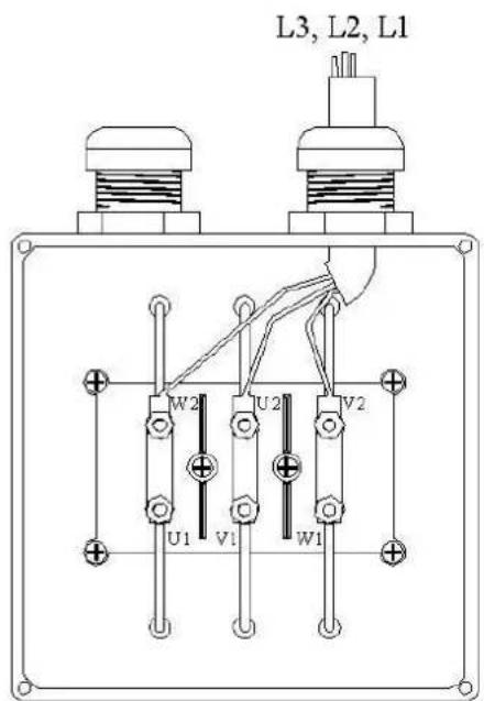
Delta (Δ)
connection

Star
(Y)
Two speed motors - 2/4 poles or 4/8 poles - Double polarity (Dahlander type) - Y/YY

L1, L2, L3

Lower speed
(higher number of poles)
(lower number of poles)
Higher
speed
Two speed motors - 4/6 poles
ALWAYS check the electrical connection scheme attached to electric box, because the following schemes are illustrative.
Double winding - Y/Y
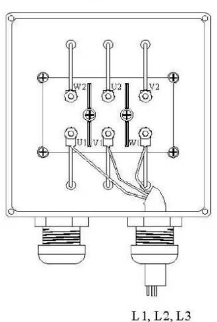
Lower speed (6 poles)
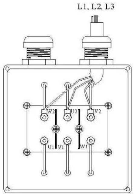
Higher speed (4 poles)
One-phase motors
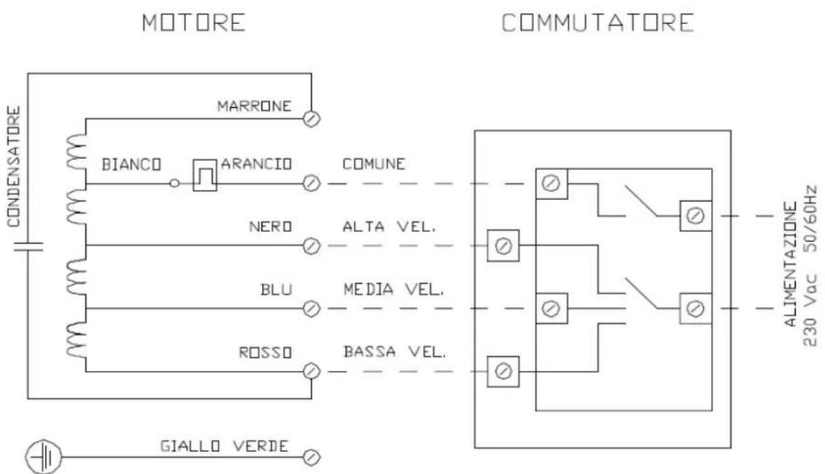
Because of the multitude of fan used, the pattern shown above is quite exemplary, ALWAYS verify the pattern indicated on the fan
brushless
| ( ) | Ca | C | Mot | (A) a | ||
| 400V | 15 m | |||||
| 0,75 kW | FG | OR 6/1K | 3x1,5+T | 13,65 | 1,3 | 0,09% |
| 1,1 kW | FG | OR 6/1KV 3x1,5+T | 13,65 1,9 0,13% | |||
| 1,5 kW | FG | OR 6/1KV 3x1,5+T | 13,65 2,6 / 3 0,18% | |||
| 2,2 kW | FG | OR 6/1KV 3x1,5+T | 13,65 4,1 / 5 0,27% | |||
| 3 kW | FG | OR 6/1KV 3x2,5+T | 18,2 5,1 / 6 0,22% | |||
| 4 kW | FG | OR 6/1KV 3x2,5+T | 18,2 7,1 / 8 0,29% | |||
| 5,5 kW | FG | OR 6/1KV 3x4+T | 24 9,5 / 10,5 0,25% | |||
| 7,5 kW | FG | OR 6/1KV 3x4+T | 24 12,7 / 14 0,34% | |||
| 11 kW | FG | OR 6/1KV 3x6+T | 30,8 18 / 20 0,34% | |||
| 15 kW | FG | OR 6/1KV | 3x10+T | 42 | 26 / 30 | 0,27% |
| 18,5 kW | FG | OR 6/1KV | 3x16+T | 56 | 32 / 35 | 0,24% |
| 22 kW | FG | OR 6/1KV | 3x16+T | 56 | 38 / 42 | 0,25% |
| 30 kW | FG | OR 6/1KV 3x25+T | 73,5 52 / 55 0,23% | |||
| 37 kW | FG | OR 6/1KV 3x25+T | 73,5 63 / 66 0,28% | |||
| 45 kW | FG | OR 6/1KV | 3x35+T | 90 | 76,5 / 80 | 0,24% |
| 55 kW | FG | OR 6/1KV | 3x50+T | 108 94 / 97 0,22% | ||
| 55 kW | FG | OR 6/1KV | 3x35+T | 128 94 / 97 0,30% | ||
| 75 kW | FG | OR 6/1KV | 3(1x50)+N35+T | 175 128 / 132 | 0,30% | |
| 75 kW | FG | OR 6/1KV | 3(1x70)+T | 155,5 128 / 132 | 0,30% | |
PLC
GND, 0-10V (Ain 1U), +10V.
GND, +10V, 0-10V o Ain 1U
0-10V
EC BRUSHLESS

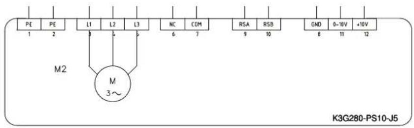


EBM-Papst
4.8.3. Safety devices on doors
Fan sections are equipped with a microswitch and/or a protection grid an inlet doors. In presence of a N.O. microswitch, connect it through an auxiliary contact in the circuit breaker; in this way as you open the fan door, it turns off anyway.
Wiring and connections of safety devices to the general safety system of the plant must be done at the installer care according to the note described at the chapter "INTRODUCTION". Safety devices should be interlocked according CEI-EN 60204-1. When a microswitch operates (or any other kind of electric protection) it must completely and irreversibly inhibit machine's working. Its restart must be allowed only manually, with an interruption and a following supply restart from the electric panel..
4.8.4. Internal unit lighting
Unit internal lamps should be cabled at installer's care directly on the lighting points provided on the unit. Lighting operation should comply with CEE standards and in particular should include an automatic switch-on operation at the moment of any safety devices intervention.
4.8.5. Unit ground connection
Unit ground connection should be made using the appropriate terminals provided outside the unit, with cables of adequate section and carefully following all procedures and standards. Grounding of the unit is fundamental requirement to comply with safety codes against electrical accidents.
Lack, or inadequate grounding relieves manufacturer from electrical accidents liability. Warning!
Installer is liable by law for the proper activation of safety devices installed in accordance to EU Directives, specially to the principle decribed at the point 4.7.3.
All cables and connections of electric parts should comply with the current IEC standards, or the standard national requirements of the country.
5. UNIT START UP
The following preliminary checks are essential before proceeding to specific start-up verifications:
1) no foreign matters or dirt should be left close to rotating parts or in the unit sections;
2) all drains should be free;
3) hydronic circuits should be regularly fed;
4) coil circuits should be fed and valves open.
5.1. Safety system
Safety systems operation and reliability must be verified by specifically checking their actual intervention on emergency conditions and ensuring that moving parts are effectively stopped; unit shall be de -energized as soon as safety devices show their proper effect.
Tests of safety systems must be repeated at least three times for each safety device, and should not be subsequent on the same system.
For unit with internal lighting, shut off due to any emergencies must cause immediate lighting of the internal lamps.
5.2. Electric motors, fans and drives
a) Check alignment of drive pulleys and their stability on shaft.
b) Check for the correct rotating direction of fans, which must be the one shown on the fan housing by an arrow; wrong rotation can be corrected by switching motor electric connections on the three-phase line.
c) After a short period of operation (12-24 hours) check the drive belt tension and adjust it, if necessary, according to procedure indicated at point 6.2..
d) Verify the actual current input and compare this value with data indicated on the unit name plate; in case actual current input is higher, it is necessary to check that:
- motor-fan group rotates freely by hand;
- fan speed is the prescribed one;
- air volume is not higher than the one indicated on the name plate;
- electric supply is correct.
e) Ensure also that all protective guards on rotating parts are held in strong position.
5.3. Air filters
Check that filters have not been damaged during transportation and/or installation and that are free from dirt or other foreign matters. If filters cells have been shipped separately, proceed to their assembly on unit, ensuring that:
1) flat filters, extended surface or metallic types, are properly inserted in their guides and that each cell is tight to the next, a slight pressure on the closing panel will ensure this detail;
2) bag type filters are properly tighten to frames by means of their springs;
3) absolute filter cells are properly mounted and their sealing gasket is tight and held in correct position by slightly fastening screws of the supporting frames;
4) roll-type filter, if any, rotates in the correct direction;
5) differential pressostats, if any, operate properly and are regularly connected.
For other filter types, particular instructions are given, when applicable.
5.4. Humidifier sections and pumps
5.4.1. Drain sumps
a) Open valves and replenish drain sumps by regulating the floating ball at a level of 1-2 cm below overflow discharge, then block floating valve arm in position.
b) Bleed-off discharge should operate continuously and uniformly in all types of humidifiers.
5.4.2. Packs and spraying nozzles
a) For the pack type humidifiers, ensure that the whole pack is wet and sprayed uniformly; the bypass valve on the water supply allows fine regulation of the water flow in order to avoid overflows.
b) For humidifying systems bearing spraying nozzles, check that water jet of each nozzle is regular and clean those nozzles that appear to be clogged.
c) The supply pressure of any humidification system which uses water must be approximately 1.5 bar.
5.4.3. Pumps
a) Check pump rotation direction and, if uncorrect, switch electric connections on the three-phase line.
b) Check pump suction and ensure is never underfed, this may cause surging and damage the electric motors.
c) Measure current input and, if higher than name plate value, check for causes prior to operating the unit.
5.5. Coils
Check that fin packs are not damaged and are clean; in case of any bends or flattening of fins for previous mishandling, use fin calibrated combs and restore proper fin conditions and spacing. Coil circuit should be vented repeatedly with pumps in operation.
In case the unit is expected to intake air at temperature below 0^ C during cold seasons or that can be held idle in freezing ambient temperature, it is mandatory that all water circuit not in use be completely drained in order to avoid ruptures due to freezing. To avoid this risk, antifreezing solutions, such as water glycol, can also be used, with adequate component percentages related to the minimum temperature that could be reached in the area.
An informative table is given, showing solution percentages according to various minimal temperatures; in any case it is recommended that tables supplied by glycol producer be fellowed.
| Glycol solution, by volume | % | in | the | Freezing | poin |
| 0 | 0 | ||||
| 10 | -5,5 | ||||
| 2 | 0 | 9 | |||
| 3 | 0 | 1 | |||
| 4 | 0 | 2 | |||
| 50 | -33 |
It should be noticed that, when using a water-glycol solution, coil performance decreases. In these cases a certain penalization should be accepted, unless such operating conditions can be taken into consideration during unit design and heat exchangers sized accordingly, to compensate for the capacity loss.
5.6. Dampers
For manually operated dampers, check that operation is smooth and it is possible to block damper in the desired position easily and efficiently.
For motorized dampers ensure there are no slowdowns or stopping in the damper movement along the entire sector. Instructions on electric connections are given by the control manufacturer and supplied with unit
6. MAINTENANCE
Warning: before any operation, turn off the main power switch.
Only the safety devices check should be done with power main supply.
6.1. Safety system
Essential safety requirements, as recommended by EU Directives, which this unit complies with, must be verified at least every 90 days.
Verification must ensure full operation of all safety devices installed and their reliability. To properly accomplish this duty, the following procedure should be considered:
1) take full note of all safety devices and other safety systems installed on the unit, by carefully examining the technical literature supplied with the unit;
2) with the unit in operation and using all due precautions, create emergency situations and cause safety systems to intervene; ve rify that in such cases unit is immediately shut off (as an example, emergency situations can be created by opening one by one all inspection doors); repeat test for two non consecutive times and for the whole series of safety devices;
3) when internal lighting is installed, check that light turns on at safety intervention, (i.e. at panel opening in the previous example);
4) check correct positioning of all static (or passive) safety devices and that they are steadily fasten to the unit parts; in particular, protection of moving parts must be stable and should be possible to disassemble them only by using special tools.
Check and tests of safety system must be recorded in the "Unit record manual". See a sample of this manual at point 6.10..
6.2. Electric motors, fans and drives
Motor and fan bearings are life-lubricated hence do not need maintenance. Only on some large size fans open type bearings needing periodical greasing are assembled, in these cases, litium grease bearings lubrification should be provided as follows:
1) carefully clean external surface of the greaser before connecting to the grease pump, to avoid dirt to be forced inside bearing;
2) use moderate pressure and carefully avoid that grease overflows from sealing gaskets;
3) after greasing, have fan to rotate for few seconds.
Every 30 days check for any wearing out signs on the fan belts and check proper belt tension as follows:
1) disassemble belt guard;
2) measure free length of the distance "D" (Fig. 7);
3) apply on the central point of the free distance "D" a force "F", as indicated in the table of Fig. 7, according to the cross section of the belt used (for belt section see "Technical Form");
| Belt cross Section | Minimum force F N | Maximum force F ( k g ) | |
| A | 7 | (0,7) | |
| B | 16 | (1,6) | |
| C | 29 | (2,9) | |
| D | 57 | (5,7) | |
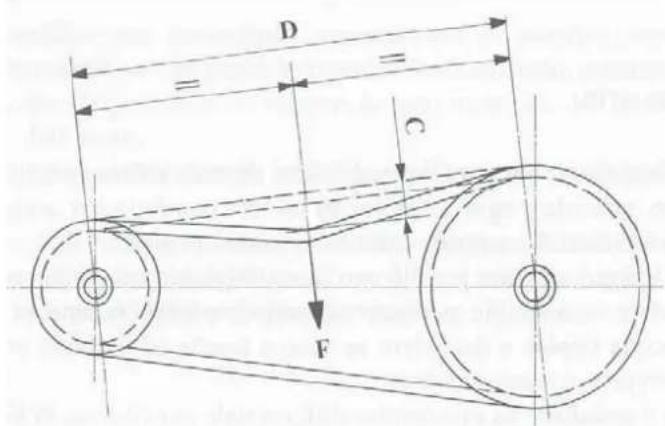
Fig. 7
4) measure deflection "C", at the center of distance "D", which must result equal to 1.5 mm per each 100 mm of free distance "D" (C = 1,5 x D/100);
5) if "C" value is lower (belt is too tensioned) adjustment is necessary through screw "A" by reducing distance between motor and fan, if "C" value is larger (belt is not much tensioned) is necessary, always through screw "A", to increase the distance between motor and fan;
6) when force "F" and deflection "C" return to correct values, reassemble belt guard by tightening all screws provided for this purpose.

Fig. 8
At motor start up belts normally slide on pulleys for 1-2 seconds. Correct tension will avoid early wear out of belts (usually due to belts too loose) or overloading bearings of motor and fan (due to belts too tensioned).
To avoid undesired unit shutdowns, change belts at least every 12 months without waiting for their complete wear out.
Changing belts is carried out with an operation similar to the one already described for their tensioning, with the additional note that:
1) untighten screw "A" until belt is easily removed from pulley grove;
2) new belts should first be tensioned with a force F1 = F x 1,3;
3) after an operation period of 12-24 hours, re-check belt tension and adjust it to the values shown on the table of Fig. 7.
6.3. Air filters
a) As filter life depends on ambient conditions in which they operate, it is important to check every 15 days for their status to ascertain chances to reach their standard maintenance schedules.
b) Every 60 days cleaning or replacement of filters is necessary; if filters are of the cleanable type they can be cleaned either by applying a vacuum to their surface or by washing with lukewarm water and detergent; bag type and absolute filters are not cleanable and must be fully replaced.
c) When a differential pressostat is mounted, filters cells must be cleaned or replaced when pressure drop reaches the maximum value recommended by the filter manufacturer (usually 200 Pa or 20 mm w.g. for corrugated filters, 300 Pa or 30 mm for bag type filters and 500 Pa or 50 mm for absolute filters).
d) Roll-type media should be replaced once completely un rolled.
Special attention should be paid for the lack of filter cleaning or replacement can cause a decrease in the unit efficiency because:
- air volume will decrease due to pressure drop increase;
- unit treatment performance will decrease and consequently lower comfort will be obtained;
- refrigeration system can be damaged in case of DX coil application.
6.4. Humidifier sections and pumps
6.4.1. Water sumps, packs and nozzles
Every 60 days open the bottom discharge and empty sumps, then wash with water jet in order to clean from dirt and mud deposited on the bottom; check and clean, if necessary, humidifier evaporative packs and overhead distribution sectors. For humidifiers with spraying nozzles, disassemble and clean those appearing clogged.
Check that bleed-off discharge flows uniformly and continuously, if necessary proceed to its cleaning.
6.4.2. Water strainers
Remove and carefully clean water strainers every 30 days, washing them with running water. Lack of strainers cleaning reduces pump performance and efficiency of humidifiers section, furthermore it can cause surging conditions with heavy damages to pumps.
6.4.3. Pumps
Pumps installed on the unit do not usually need maintenance being of the lifelong nonmaintenance type. It is only necessary to check, during section standard checks, that their suction is always under the normal water level.
In case of long idle periods, pumps must operate for short cycles from time to time.
After having carried out all operation described, replenish sump and regulate floating valve so to maintain a water level of 1-2 cm below overflow discharge, then block the floating arm in position.
6.5 Coils
When cleaning or replacing air filters, check for status and cleanliness of coil fin packs. Lack of or late filter maintenance can impair filters and consequently allow dirt and foreign matters to clog coil fin packs.
In this case do not use any cleaning system that may damage the fins, but use compressed air in counterflow to the normal air direction.
In case of deformations, fins can be restored by using a suitable calibrated fin comb.
When coils are seriously damaged and must be disassembled, proceed as follows:
1) shut off inlet and outlet valves and drain coil by opening vent and discharge;
2) disconnect coil headers from water circuit;
3) take out headers cover panel and, inside unit, the side metal sheet protections;
4) ascertain that external available space is sufficient for the complete coil withdrawal, as prescribed in 4.2. (Service area requirements);
5) by lifting headers end slide coil out on its guide rails, possibly greased if necessary;
6) in case unit must continue to operate without the coil, reassemble header cover panel and close connection holes with whatever means.
Unit can eventually be re-assembled with the same procedure but in the contrary order.
6.6. Dampers
Every 180 days check that dampers complete their full movement freely and without stops, particularly the motorized ones.
For manually controlled dampers, check the holding device that keeps them in position.
6.7. Unit shut down precautions
When unit is expected to be idle for long periods, it is recommended to use the following simple precautions:
1) disconnect power supply on the general electric panel and place a warning notice that unit is idle;
2) shut off water supply;
3) empty unit sumps as per point 6.4.1.;
4) shut off coil valves and drain coils;
5) shut all dampers off;
6) if unit is equipped with absolute filters, take them out and store in sealed boxes;
7) every 30 days have motors, fan and pumps to rotate for few seconds to avoid damages to bearing.
In case unit could remain idle at ambient temperature below 0^ C, it is particularly important to proceed to coil drainage as per point 4), furthermore it is necessary to empty all traps and replenish them with an antifreeze solution as per table at point 5.5..
6.8. Summary schedule for periodical maintenance
| 15 gg. | 30 gg. | 60 gg. | 90 gg. | 180 gg. | 12 mesi | |
| security systems and testing | ** | |||||
| Fan motor transmiss.- control straps- Replacement belts- Bearing Lubricants | ** | *** | ||||
| air filters control- cleaning or replacement | ** | ** | ||||
| humidification section.and wash-basins _parcels and nozzleswater filters- pump control | ** | ****** | ||||
| Batteries control | ** | |||||
| Damper control | ** |
"Check and tests" of safety systems must be recorded with all other maintenance interventions in the "Unit record manual". A sample of this manual is shown at point 6.10.
All maintenance periods refer to unit effective operation days with a continuous service of 12 hour/day. For operational periods longer of shorter than indicated, maintenance schedule must be adjusted accordingly.
"Check and tests" of all safety systems and bearing greasing must be accomplished in any case every 12 months, even if unit is operating for limited periods only.
6.9. Trouble shooting
| Trouble | Possible Cause | How to solve |
| 1) Active safety fails to operate | Electric system failureElectric components failure | Call electric maintenanceReplace component or call Service |
| 2) Insufficient air volume Dirty filters | Dirty fin packBelts worn outLoose beltsWrong fan rotationEcessive pressure dropDampers shut off | Clean or replace filtersClean coilsReplace beltsAdjust driveChange electric motor connectionsCheck system designCall for fan section modificationOpen dampers and check for correct operation of their control |
| 3) Ecessive air volume | System pressure drop lower than forecastedComponents (filters?) missingInspection panels open | Check dampersCheck system designCall for fan drive modificationCheck inside unit and install missing elementsShut panels off |
| 4) Low thermal capacity | Insufficient air volumeLack or insufficient supply to coilsCoil connections invertedFin pack dirty or batteredAir bubbles in circuit, on liquid coilsFluid exchange temperatures not at design values | See trouble 2)Open shut off valvesCheck pump rotation and, if wrong, change pump electric connectionsCheck pump flowInvert inlet/outlet connectionsClean and comb fin packPurge coilsCheck thermostats on thermal sources (boilers or chillers) |
| 5) Insufficient humidification | Clogged nozzlesInsufficient water supplyPack not completely wetWater supply shut offInefficient evaporative packsInsufficient pre-heating | Clean nozzlesOpen supply valvedownstream pumpAdjust sump levelOpen supply valvedownstream pumpAdjust sump levelOpen water supply valveClean or replace evaporative packsCheck pre -heating coil control |
| 6) Droplets carryover | Ecessive air volumeEcessive water flow on packs | See trouble 3)Adjust supply valvedownstream pump |
| 7) Excessive noise and/or vibrations | Warn bearings on fan or motorFan discharge isolator too compressedFan isolators inadequateRotating parts out of balanceRotating parts loose on shafts (fan wheel and/or pulleys)Pulleys out of alignmentForeign matters in rotating partsTrasmission safety guard not tightenPanels fixing screws untightenOne phase out on motor power supplyIncorrect power main supply | Replace bearingsAdjust fan positioningCall for serviceCall ServiceBalance or replace rotating partsCall ServiceFirmly tighten fixing screws on wheel and pulley hubsAlign pulleys and tighten fixing screwsClean internal partTighten fixing screwsCarefully and smoothly tighten screws paying attention not to bend panel surfaceCheck terminals and tighten boltsCheck power supply comparing with electric characteristic on name plate |
6.10 Unit record manual
| DATE | CHECK OR TROUBLE | RESULT | INTERVENTION | SIGNATURE |
7. REPLACEMENT PARTS
7.1. Unit identification
Central station model is univoquely identified by the Type and Series indicated on the name plate, normally located on the external surface of the inspection panel of the fan section. Same identification data are indicated at Chapter 1 - UNIT IDENTIFICATION -, on the "Technical Form" and on the "GUARANTEE CERTIFICATE".
7.2. Identification of the part to be replaced
Once ascertained the component to be replaced, for normal wearing out or for any falts, refer to the "Technical Form" and identify its correct type and description in order to place a correct and clear order.
7.3. Replacement parts ordering
Order should be placed by mail, fax or e-mail:
1) type and serial number as indicated at point 7.1.;
2) type and full description of the parts requested as indicated at point 7.2.;
3) quantity (number of pieces) requested for each item.
will inform on price and delivery of parts by return.
It is recommended that only original replacement parts be used, of same type and Quality as selected at unit design; this will guarantee unit performance and reliability.
8. DISMANTLEMENT AND MATERIALS' DISPOSAL
8.1 Unit disconnection
Disconnection operations must be effected by a qualified technicist, who must follow the dispositions provided in this manual into the section “residual risks”.
Before the disconnection of the unit the following materials (if present) must be recovered:
- Refrigerant gas, when it is impossible to isolate circuits, for direct expansion coil units. The extraction of refrigerant gas must be effected with intake devices, which operate in a closed circuit to assure that no material will be released in the atmosphere
- Antifreeze fluid into the circuits: during its removal it is important to avoid any losses into the environment. Antifreeze fluid must be stored into appropriate container, as provided by the laws in force.
IMPORTANT
- During recovery operations it is important to pay a great attention to avoid damages to people or environmental pollution
Awaiting dismantlement and disposal moment, the unit can be stored even outdoor, because bad weather and sudden changes in temperature cannot cause damages for the environment.
- During dismantlement phase the fan, the coil, the motor (if they are still usable) can be recovered in specialized centres
■ Recover and dispose of materials according to national laws in force
- In the following table you can find the materials employed to build the unit, even those which are present in its components
| MATERIAL | EMPLOYMENT | QUANTITY OF MATERIAL WITH REFERENCE TO TOTAL WEIGHT | PRESENCE |
| Rolled metal | Base, panels, fan, electric motor | High | Always present |
| Aluminium | Case, electric motor's structure, coils, dampers, droplet separators | High | Always present |
| Copper | Coils, motor | Medium | Always present |
| Polyurethane | Panels | High | Optional |
| Mineral wood | Panels, sound attenuators | High | Optional |
| Gummy material | Gaskets, antivibration joints | Low | Always present |
| Nylon | Handles, clasps, panelblocks | Low | Always present |
| Paper | Steaming pack | Medium | Optional |
! MATERIALS MUST BE ALWAYS DELIVERED TO AUTHORIZED CENTRES FOR DISPOSAL OPERATIONS
****************************************************************************************
In order to better assist its customers and users of its equipment, will be obliged if any changes in unit property are communicated by simply giving:
- serial number or construction number of the unit;
- new user's name and address;
- new unit location in case of change in installation address.
INDICATIVE POSITIONING OF ADHESIVE SIGNALING AND PLAQUE OF RECOGNITION

A duplicate of this manual can be requested in case of damage or loss.
This manual represents the current state-of-the-art technology at publication.
Modifications can be made without prior notice
- CE
- INDICE GENERALE
- INTRODUCTION
- GENERAL DISPOSITIONS
- SOUND LEVELS
- DIMENSIONS
- SAFETY INTEGRATION PRINCIPLES
- RESIDUAL RISKS
- SECURITY INSTRUCTIONS CAUTION!
- ANY OPERATION WHICH CAN PRODUCE DANGEROUS SITUATIONS IS INDICATED IN THIS MANUAL. IT ALSO CONTAINS PRECAUTIONARY MEASURES FOR ANY SPECIFIC CASE.
- PROHIBITIONS!
- OBLIGATIONS!
- CAUTION!
- UNIT IDENTIFICATION
- INSTRUCTIONS FOR WORKER'S SAFETY
- CHECK AT RECEIVAL
- TRASPORTATION AND HANDLING
- INSTALLATION
- Preliminary notice
- Service area requirements
- Section coupling and bolting
- Coil connections
- Water coils
- Steam coils
- Direct expansion coils
- Electric heaters
- Hydronic connections
- Connection to water supply systems for humidification
- Air connections
- Electrical connections
- Electric heaters
- Electric motors
- Electrical connection schemes
- Single speed motors
- Two speed motors - 4/6 poles
- Safety devices on doors
- Internal unit lighting
- Unit ground connection
- UNIT START UP
- Safety system
- Electric motors, fans and drives
- Air filters
- Humidifier sections and pumps
- Drain sumps
- Packs and spraying nozzles
- Pumps
- Coils
- Dampers
- MAINTENANCE
- Warning: before any operation, turn off the main power switch.
- Only the safety devices check should be done with power main supply.
- Safety system
- Electric motors, fans and drives
- Air filters
- Humidifier sections and pumps
- Water sumps, packs and nozzles
- Water strainers
- Pumps
- Coils
- Dampers
- Unit shut down precautions
- Summary schedule for periodical maintenance
- Trouble shooting
- REPLACEMENT PARTS
- Unit identification
- Identification of the part to be replaced
- Replacement parts ordering
- DISMANTLEMENT AND MATERIALS' DISPOSAL
- Unit disconnection
- IMPORTANT
- ! MATERIALS MUST BE ALWAYS DELIVERED TO AUTHORIZED CENTRES FOR DISPOSAL OPERATIONS
- INDICATIVE POSITIONING OF ADHESIVE SIGNALING AND PLAQUE OF RECOGNITION
Brand : FERROLI
Model : Fahu
Category : Air Handling Unit