
CG 24EKS(L) - Hedge Trimmer HITACHI - Free user manual and instructions
Find the device manual for free CG 24EKS(L) HITACHI in PDF.


| Product type | Gas hedge trimmer |
| Brand | Hitachi |
| Model | CG 24EKS(L) |
| Blade length | 600 mm |
| Tooth spacing | 24 mm |
| Engine | 2-stroke, 24 cc |
| Power | 0.9 kW |
| Idle speed | 7000 rpm |
| Fuel | Gas-oil mixture 50:1 |
| Fuel tank capacity | 0.4 L |
| Weight (without fuel) | 5.3 kg |
| Dimensions (L x W x H) | 1020 × 290 × 240 mm |
| Guaranteed sound power level | 108 dB(A) |
| Vibration level (front handle) | 7.8 m/s² |
| Anti-vibration system | Yes |
| Blade guard | Included |
| Blade brake | No |
| Electronic ignition | Yes |
| Air filter maintenance | Regular cleaning with soapy water |
| Spark plug maintenance | Check and replace if necessary |
| Blade sharpening | Recommended after heavy use |
| Spare parts available | Blade, spark plug, filter, carburetor, etc. |
| Repairability index | 8.2/10 |
Frequently Asked Questions - CG 24EKS(L) HITACHI
User questions about CG 24EKS(L) HITACHI
0 question about this device. Answer the ones you know or ask your own.
Ask a new question about this device
Download the instructions for your Hedge Trimmer in PDF format for free! Find your manual CG 24EKS(L) - HITACHI and take your electronic device back in hand. On this page are published all the documents necessary for the use of your device. CG 24EKS(L) by HITACHI.
USER MANUAL CG 24EKS(L) HITACHI
Grass Trimmer/Brush Cutter
natural_image
Technical line drawing of a mechanical tool labeled CG24EKS (L), showing a lever and base mount (no text or symbols on the diagram itself)

SAFETY INSTRUCTIONS AND INSTRUCTION MANUAL
WARNING
IMPROPER OR UNSAFE use of this power tool can result in death or serious bodily injury!
This manual contains important information about product safety. Please read and understand this manual BEFORE operating the power tool. Please keep this manual available for other users and owners before they use the power tool. This manual should be stored in safe place.
INSTRUCTIONS DE SECURITE ET MODE D'EMPLOI
⚠ AVERTISSEMENT
NOTE: Some units do not carry them.
| Symbols⚠ WARNINGThe following show symbols used for the machine. Be sure that you understand their meaning before use. | |||
 | It is important that you read, fully understand and observe the following safety precautions and warnings. Careless or improper use of the unit may cause serious or fatal injury. |  | Shows maximum shaft speed. Do not use the cutting attachment whose max speed is below the shaft speed. |
 | Read, understand and follow all warnings and instructions in this manual and on the unit. |  | Gloves should be worn when necessary, e.g., when assembling cutting equipment. |
 | Always wear eye, head and ear protectors when using this unit. |  | Use anti-slip and sturdy footwear. |
 | Do not use metal/rigid blades when this sign is shown on the unit. | 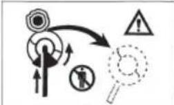 | Blade thrust may occur when the spinning blade contacts a solid object in the critical area. A dangerous reaction may occur causing the entire unit and operator to be thrust violently. This reaction is called blade thrust. As a result, the operator may lose control of the unit which may cause serious or fatal injury. Blade thrust is more likely to occur in areas where it is difficult to see the material to be cut. |
 | Keep all children, bystanders and helpers 50 ft (15 m) away from the unit. If anyone approaches you, stop the engine and cutting attachment immediately. | ||
 | Be careful of thrown objects. | 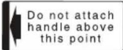 | Indicate handle location. Do not attach handle above this point. |
 | Indicates blade guard location for a trimmer head or semi-auto cutting head. | ||
| Before using your machineRead the manual carefully.Check that the cutting equipment is correctly assembled and adjusted.Start the unit and check the carburetor adjustment. See “MAINTENANCE”. | |||
Contents
WHAT IS WHAT 3
WARNINGS AND SAFETY INSTRUCTIONS ..... 4
WARRANTY 5
SPECIFICATIONS....6
ASSEMBLY PROCEDURES 7
OPERATING PROCEDURES 8
MAINTENANCE 10
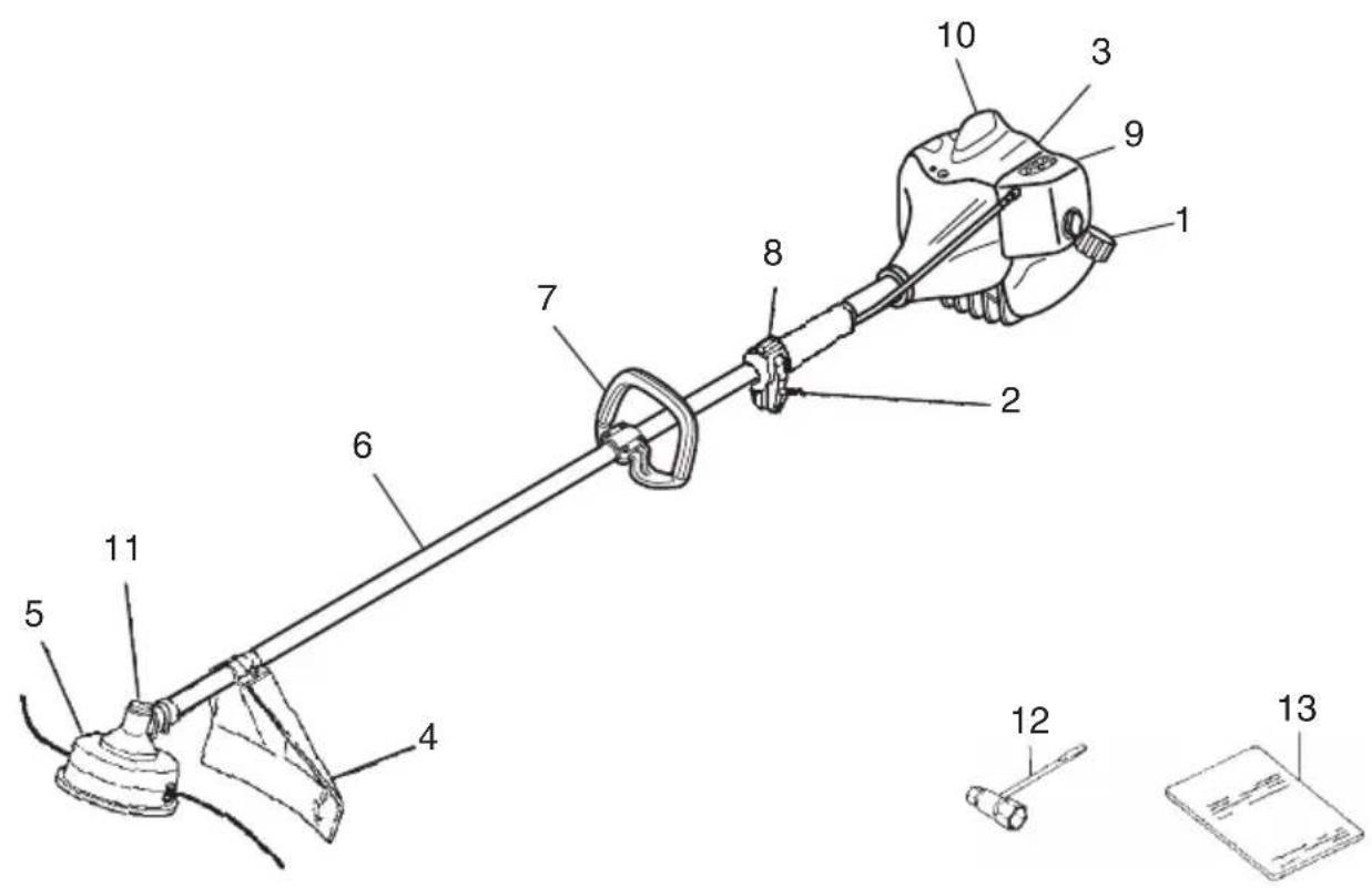
WHAT IS WHAT
- Fuel cap
- Throttle trigger
- Starter handle
- Blade guard
- Cutting attachment
- Drive shaft tube
- Handle
- Ignition switch
- Choke lever
- Engine
- Angle transmission
- Combi box spanner
- Handling instructions
WARNINGS AND SAFETY INSTRUCTIONS
Operator safety
○ Always wear a safety face shield or goggles.
○ Always wear heavy, long pants, boots and gloves. Do not wear loose clothing, jewelry, short pants, sandals or go barefoot. Secure hair so it is above shoulder length.
○ Do not operate this tool when you are tired, ill or under the influence of alcohol, drugs or medication.
Never let a child or inexperienced person operate the machine.
○ Wear hearing protection. Pay attention to your surroundings. Be aware of any bystanders who may be signaling a problem. Remove safety equipment immediately upon shutting off engine.
○ Wear head protection.
Never start or run the engine inside a closed room or building. Breathing exhaust fumes can kill.
○ Keep handles free of oil and fuel.
○ Keep hands away from cutting equipment.
○ Do not grab or hold the unit by the cutting equipment.
When the unit is turned off, make sure the cutting attachment has stopped before the unit is set down.
When operation is prolonged, take a break from time to time so that you may avoid possible Hand-Arm Vibration Syndrome (HAVS) which is caused by vibration.
WARNING
● Antivibration systems do not guarantee that you will not sustain Hand-Arm Vibration Syndrome or carpal tunnel syndrome. Therefore, continual and regular users should monitor closely the condition of their hands and fingers. If any symptoms of the above appear, seek medical advice immediately.
- If you are using any medical electric/electronic devices such as a pacemaker, consult your physician as well as the device manufacturer prior to operating any power equipment.
Unit/machine safety
○ Inspect the entire unit/machine before each use. Replace damaged parts. Check for fuel leaks and make sure all fasteners are in place and securely tightened.
○ Replace parts that are cracked, chipped or damaged in any way before using the unit/machine.
○ Make sure the safety guard is properly attached.
- Keep others away when making carburetor adjustments.
○ Use only accessories as recommended for this unit/machine by the manufacturer.
WARNING
Never modify the unit/machine in any way. Do not use your unit/machine for any job except that for which it is intended.
Fuel safety
○ Mix and pour fuel outdoors and where there are no sparks or flames.
○ Use a container approved for fuel.
Do not smoke or allow smoking near fuel or the unit/machine or while using the unit/machine.
○ Wipe up all fuel spills before starting engine.
○ Move at least 10 ft (3 m) away from fueling site before starting engine.
○ Stop engine before removing fuel cap.
○ Empty the fuel tank before storing the unit/machine. It is recommended that the fuel be emptied after each use. If fuel is left in the tank, store so fuel will not leak.
○ Store unit/machine and fuel in area where fuel vapors cannot reach sparks or open flames from water heaters, electric motors or switches, furnaces. etc.
WARNING
Fuel is easy to ignite or get explosion or inhale fumes, so that pay special attention when handling or fi lling fuel.
Cutting safety
○ Do not cut any material other than grass and brush.
○ Inspect the area to be cut before each use. Remove objects which can be thrown or become entangled.
☐ For respiratory protection, wear an aerosol protection mask when cutting the grass after insecticide is scattered.
Keep others including children, animals, bystanders and helpers outside the 50 ft (15 m) hazard zone. Stop the engine immediately if you are approached.
○ Always keep the engine on the right side of your body.
○ Hold the unit/machine firmly with both hands.
○ Keep firm footing and balance. Do not over-reach.
Keep all parts of your body away from the muffler and cutting attachment when the engine is running.
○ Keep cutting attachment below waist level.
When relocating to a new work area, be sure to shut off the machine and ensure that all cutting attachments are stopped.
○ Never place the machine on the ground when running.
○ Always ensure that the engine is shut off and any cutting attachments have completely stopped before clearing debris or removing grass from the cutting attachment.
○ Always carry a first-aid kit when operating any power equipment.
Never start or run the engine inside a closed room or building and/or near infl ammable liquids. Breathing exhaust fumes can kill.
Maintenance safety
○ Maintain the unit/machine according to recommended procedures.
○ Disconnect the spark plug before performing maintenance except for carburetor adjustments.
- Keep others away when making carburetor adjustments.
○ Use only genuine Hitachi replacement parts as recommended by the manufacturer.
Transport and storage
○ Carry the unit/machine by hand with the engine stopped and the muffler away from your body.
○ Allow the engine to cool, empty the fuel tank, and secure the unit/machine before storing or transporting in a vehicle.
○ Empty the fuel tank before storing the unit/machine. It is recommended that the fuel be emptied after each use. If fuel is left in the tank, store so fuel will not leak.
○ Store unit/machine out of the reach of children.
○ Clean and maintain the unit carefully and store it in a dry place.
○ Make sure engine switch is off when transporting or storing.
○ If your unit has blade, when transporting in a vehicle, cover blade with blade cover.
If situations occur which are not covered in this manual, take care and use common sense. Contact your Hitachi dealer if you need assistance. Pay special attention to statements preceded by the following words:
WARNING
Indicates a strong possibility of severe personal injury or loss of life, if instructions are not followed.
CAUTION
Indicates a possibility of personal injury or equipment damage, if instructions are not followed.
NOTE
Helpful information for correct function and use.
CAUTION
Do not disassemble the recoil starter. You may get a possibility of personal injury with recoil spring.
WARRANTY
The warranties provided by Hitachi Koki U.S.A., Ltd. are explained in the warranty card enclosed with this product titled "Hitachi Outdoor Power Equipment Limited Warranty".
Therefore, the two year warranty for “the first commercial end user” and one year warranty for “rental applications” mentioned in the warranty card are provided on CG24EKS(L).
SPECIFICATIONS
| Model CG24EKS (L) | ||
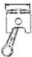 | Engine Size (cu. in.) 1.46 (23.9 ml) | |
 | Spark Plug Champion CJ6 | |
 | Fuel Tank Capacity (fl . oz) 17.6(0.52 l) | |
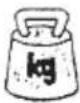 | Dry Weight (lbs) 11.2 (5.1 Kg) | |
 | Sound pressure level LpA (dB (A))(EN27917) | 95.2 |
 | Sound power level LwA (dB (A)) | 112 |
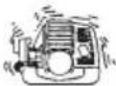 | Vibration level (m/s2)(ISO7916) | |
| Front handle | 5.3 | |
| Rear handle | 3.2 | |
NOTE
Equivalent noise level/vibration level are calculated as the time-weighted energy total for noise/vibration levels under various working conditions with the following time distribution: 1/2 Idle, 1/2 racing.
* All data subject to change without notice.
ASSEMBLY PROCEDURES
Drive shaft to engine (Fig. 1)
Loosen tube locking bolt (1) about ten turns so that the bolt point will not obstruct drive shaft tube to be inserted. When inserting drive shaft tube, hold the tube locking bolt outward preventing inside fitting from obstructing as well.
Insert the drive shaft into the clutch case of the engine properly until the marked position (2) on the drive shaft tube meets the clutch case.
Some models may come with the drive shaft already installed.
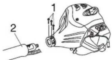
Fig. 1
NOTE
When it is hard to insert drive shaft up to the marked position on the drive shaft tube, turn drive shaft by the cutter mounting end clockwise or counter-clockwise. Tighten tube locking bolt lining up the hole in the shaft tube. Then tighten clamp bolt securely.
Installation of handle
WARNING
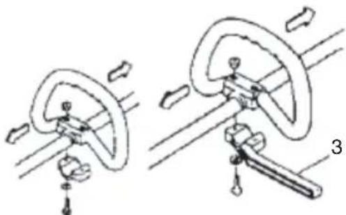
When you use steel/rigid blades on straight shaft trimmers or brush cutters, always use a barrier bar (3) and shoulder harness with the loop handle. (Fig. 2)
natural_image
Mechanical diagram showing two configurations of a rotating component with directional arrows indicating motion (no text or symbols present)Fig. 2
Attach the handle to the drive shaft tube with the angle towards the engine.
Adjust the location to the most comfortable position before operation.
NOTE
If your unit has handle location label on drive shaft tube, follow the illustration.
Throttle wire / stop cord
Remove air cleaner cover. (Fig. 3)
Connect stop cords. (Fig. 4)
If the throttle outer end (4) is threaded on your unit, screw it into the cable adjuster stay (5) all the way, and then tighten this cable end using the adjuster nut (8) against the cable adjuster stay (9).
Connect throttle wire end (6) to carburetor (7) and install swivel cap (9). (Fig. 5)
Cover throttle wire and stop cords together with protective tube provided up to air cleaner cover. (Fig. 6)
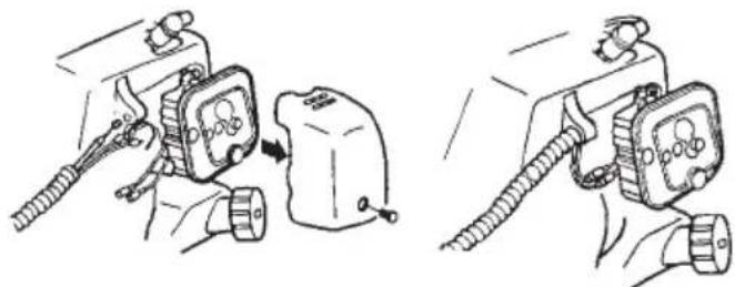
natural_image
Illustration of two hand-cranked electrical connector assemblies with no visible text or symbolsFig. 3 Fig. 4
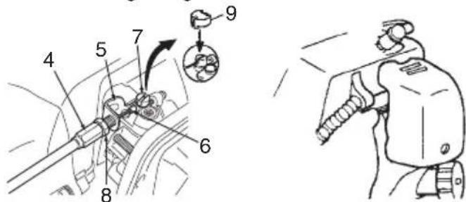
Fig. 6Fig. 5
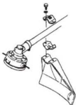
Installation of blade guard (Fig. 7)
natural_image
Technical line drawing of a mechanical device with no visible text or symbolsFig. 7
Install the blade guard on drive shaft tube. Tighten the guard bracket firmly so that the blade guard does not swing or move down during operation.
CAUTION
Some blade guards are equipped with sharp line limiters. Be careful with handling it.
NOTE
○ If your unit has guard location label on drive shaft tube, follow the indication.
Installation of cutting blade (Fig. 8)
(If so equipped)
When installing a cutting blade, make sure that there are no cracks or any damage in it and that the cutting edges are facing the correct direction.
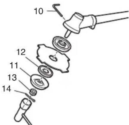
Fig. 8
NOTE
○ When installing cutter holder cap (11), be sure to set concave side upward.
Insert the alien wrench (10) into the hole of the angle transmission in order to lock the cutter holder (12). Please note that the cutter fi xing bolt or nut (13) has left-handed threads, (clockwise to loosen/ counter-clockwise to tighten). Tighten the fi xing bolt or nut with the box wrench.
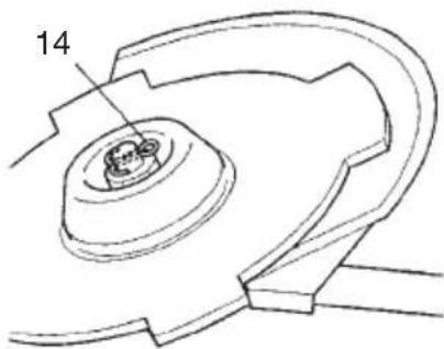
○ If your unit is of a nut securing type and equipped with a cotter pin, the blade must be retained with a new pin (14) each time installed. (Fig. 9)
natural_image
Technical line drawing of a mechanical component with no visible text or symbolsFig. 9
CAUTION
● Before operation, make sure the blade has been properly installed.
- If your unit is equipped with protection cover under a cutting blade, check it for wear or cracks before operation. If any damage or wear is found, replace it, as it is an article of consumption.
WARNING
For Hitachi heads, use only flexible, non-metallic line recommended by the manufacturer. Never use wire or wire ropes. They can break off and become a dangerous projectile.
OPERATING PROCEDURES
Fuel (Fig. 10)
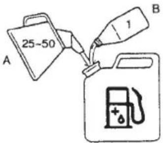
Fig. 10
WARNING
● The trimmer is equipped with a two-stroke engine. Always run the engine on fuel, which is mixed with oil.
Provide good ventilation, when fueling or handling fuel.
● Fuel contains highly flammable and it is possible to get the serious personal injury when inhaling or spilling on your body. Always pay attention when handling fuel. Always have good ventilation when handling fuel inside building.
Fuel
○ Always use branded 89 octane unleaded gasoline.
○ Use genuine two-cycle oil or use a mix between 25:1 to 50:1, please consult the oil bottle for the ratio or Hitachi dealer.
If genuine oil is not available, use an anti-oxidant added quality oil expressly labeled for air-cooled 2-cycle engine use (JASO FC GRADE OIL or ISO EGC GRADE). Do not use BIA or TCW (2-stroke water-cooling type) mixed oil.
○ Never use multi-grade oil (10 W/30) or waste oil.
○ Always mix fuel and oil in a separate clean container.
Always start by fi ling half the amount of fuel, which is to be used. Then add the whole amount of oil. Mix (shake) the fuel mixture. Add the remaining amount of fuel.
Mix (shake) the fuel-mix thoroughly before filling the fuel tank.
Fueling
WARNING
● Always shut off the engine before refueling.
● Slowly open the fuel tank, when filling up with fuel, so that possible over-pressure disappears.
● Tighten the fuel cap carefully, after fueling.
● Always move the trimmer at least 10 ft (3 m) from the fueling area before starting.
● Always wash any spilled fuel from clothing immediately with soap.
● Be sure to check for any fuel leakage after refueling.
Before fueling, clean the tank cap area carefully, to ensure that no dirt falls into the tank. Make sure that the fuel is well mixed by shaking the container, before fueling.
Starting
CAUTION
Before starting, make sure the cutting attachment does not touch anything.
- Set ignition switch (15) to ON position. (Fig. 11)
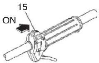
Fig. 11
* Push priming bulb (16) several times so that fuel flows through return pipe (17). (Fig. 12)
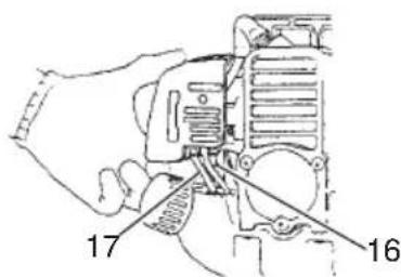
Fig. 12
- Set choke lever (18) to CLOSED position. (Fig. 13)
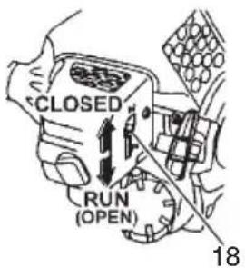
Fig. 13
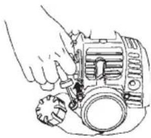
- Pull recoil starter briskly, taking care to keep the handle in your grasp and not allowing it to snap back. (Fig. 14)
natural_image
Line drawing of a hand using a tool to adjust or install a mechanical component (no text or symbols visible)Fig. 14
- When you hear the engine want to start, return choke lever to RUN position (open). Then pull recoil starter briskly again.
NOTE
If engine does not start, repeat procedures from 2 to 5.
- Then allow the engine about 2–3 minutes to warm up before subjecting it to any load.
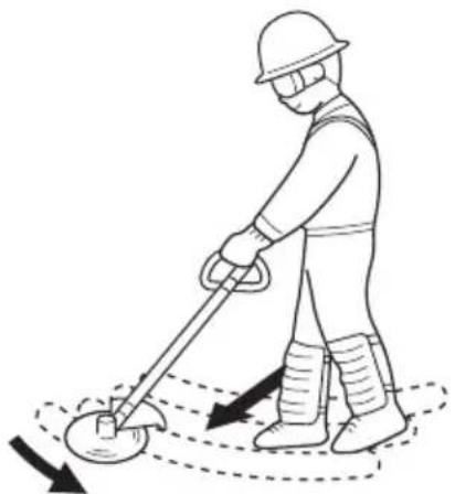
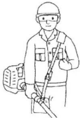
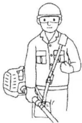
Cutting (Fig. 15, 16, 17)
When cutting, operate engine at over 6,500 min ^-1 . Extended time of use at low rpm may wear out the clutch prematurely.
○ Cut grass from right to left.
○ Blade thrust may occur when the spinning blade contacts a solid object in the critical area.
A dangerous reaction may occur causing the entire unit and operator to be thrust violently. This reaction is called blade thrust. As a result, the operator may lose control of the unit which may cause serious or fatal injury. Blade thrust is more likely to occur in areas where it is difficult to see the material to be cut.
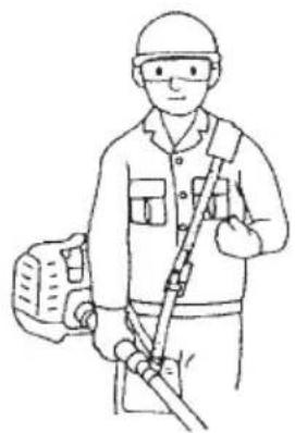
○ Wear the harness as shown in the figure (if so equipped). The blade turns counter-clockwise, therefore, be advised to operate the unit from right to left for efficient cutting. Keep onlookers out of working area at least 50 ft (15 m).
natural_image
Line drawing of a person using a metal detector to measure a circular object, with arrows indicating motion (no text or symbols)Fig. 15
natural_image
Line drawing of a person in safety gear holding equipment (no text or symbols)Fig. 16
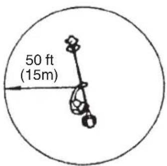
Fig. 17
WARNING
If cutting attachment should strike against stones or other debris, stop the engine and make sure that the attachment and related parts are undamaged. When grass or vines wrap around attachment, stop engine and attachment and remove them.
Stopping (Fig. 18)
Decrease engine speed and run at an idle for a few minutes, then turn off ignition switch (15).
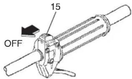
Fig. 18
WARNING
A cutting attachment can injure while it continues to spin after the engine is stopped or power control is released. When the unit is turned off, make sure the cutting attachment has stopped before the unit is set down.
Semi-auto cutting head
When cutting, operate engine at over 6,500 min ^-1 . Extended time of use at low revolution may wear out the clutch prematurely.
○ Cut grass from right to left.
WARNING
A cutting attachment can injure while it continues to spin after the engine is stopped or power control is released. When the unit is turned off, make sure the cutting attachment has stopped before the unit is set down.
MAINTENANCE
MAINTENANCE, REPLACEMENT OR REPAIR OF THE EMISSION CONTROL DEVICES AND SYSTEMS MAY BE PERFORMED BY ANY NON-ROAD ENGINE REPAIR ESTABLISHMENT OR INDIVIDUAL.
Carburetor adjustment (Fig. 19)
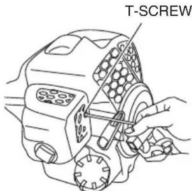
Fig. 19
WARNING
● The cutting attachment may be spinning during carburetor adjustments.
● Never start the engine without the complete clutch cover and tube assembled! Otherwise the clutch can come loose and cause personal injuries.
In the carburetor, fuel is mixed with air. When the engine is test run at the factory, the carburetor is basically adjusted. A further adjustment may be required, according to climate and altitude. The carburetor has one adjustment possibility:
T = Idle speed adjustment screw.
Idle speed adjustment (T-Screw)
Check that the air fi Iter is clean. When the idle speed is correct, the cutting attachment will not rotate. If adjustment is required, close (clockwise) the T-screw, with the engine running, until the cutting attachment starts to rotate. Open (counter-clockwise) the screw until the cutting attachment stops. You have reached the correct idle speed when the engine runs smoothly in all positions well below the rpm when the cutting attachment starts to rotate.
If the cutting attachment still rotates after idle speed adjustment, contact your Hitachi dealer.
NOTE
Standard Idle speed is 2,800 - 3,200 min ^-1 .
WARNING
When the engine is idling the cutting attachment must under no circumstances rotate.
Air fi Iter (Fig. 20)
The air fi Iter must be cleaned from dust and dirt in order to avoid:
○ Carburetor malfunctions
○ Starting problems
○ Engine power reduction
○ Unnecessary wear on the engine parts
○ Abnormal fuel consumption
Clean the air fi Iter daily or more often if working in exceptionally dusty areas.
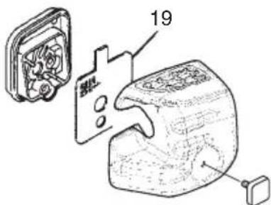
Fig. 20
Cleaning the air fi Iter
Remove the air filter cover and the filter (19). Rinse it in warm soap suds. Check that the fi liter is dry before reassembly. An air fi liter that has been used for some time cannot be cleaned completely. Therefore, it must regularly be replaced with a new one. A damaged fi liter must always be replaced.
Fuel fi Iter (Fig. 21)
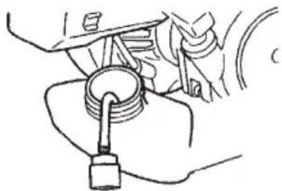
Drain all fuel from fuel tank and pull fuel filter line from tank. Pull fi Iter element out of holder assembly and rinse element in warm water with detergent.
Rinse thoroughly until all traces of detergent are eliminated. Squeeze, do not wring, away excess water and allow element to air dry.
NOTE
If element is hard due to excessive dirt buildup, replace it.
natural_image
Line drawing of a hand holding a mechanical component with a key inserted (no text or symbols)Fig. 21
Spark plug (Fig. 22)
The spark plug condition is influenced by:
○ An incorrect carburetor setting
○ Wrong fuel mixture (too much oil in the gasoline)
○ A dirty air fi Iter
○ Hard running conditions (such as cold weather)
These factors cause deposits on the spark plug electrodes, which may result in malfunction and starting diffi culties. If the engine is low on power, diffi cult to start or runs poorly at idling speed, always check the spark plug fi rst. If the spark plug is dirty,
clean it and check the electrode gap. Re-adjust if necessary. The correct gap is 0.024" (0.6 mm). The spark plug should be replaced after about 100 operation hours or earlier if the electrodes are badly eroded.
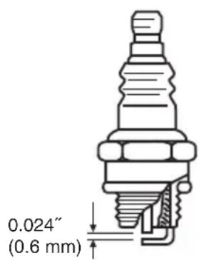
Fig. 22
NOTE
In some areas, local law requires using a resistor spark plug to suppress ignition signals. If this machine was originally equipped with resistor spark plug, use same type of spark plug for replacement.
Angle transmission (Fig. 23)
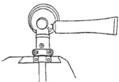
Check angle transmission or angle gear for grease level about every 50 hours of operation by removing the grease filler plug on the side of angle transmission. If no grease can be seen on the flanks of the gears, fi ll the transmission with quality lithium based multipurpose grease up to 3/4. Do not completely fill the transmission.
natural_image
Simple line drawing of a mechanical device with a lever and base mount (no text or symbols)Fig. 23
Maintenance schedule
Below you will find some general maintenance instructions. For further information please contact your Hitachi dealer.
Daily maintenance
○ Clean the exterior of the unit.
○ Check that the harness is undamaged.
☐ If your unit has blade, check the blade guard for damage or cracks. Change the guard in case of impacts or cracks.
☐ Check that the cutting attachment is properly centred, sharp, and without cracks. An off-centre cutting attachment induces heavy vibrations that may damage the unit.
○ Check that the cutting attachment nut is sufficiently tightened.
☐ If your unit has blade, make sure that the blade transport guard is undamaged and that it can be securely fitted.
○ Check that nuts and screws are sufficiently tightened.
Weekly maintenance
○ Check the starter, especially the cord and return spring.
○ Clean the exterior of the spark plug.
○ Remove it and check the electrode gap. Adjust it to 0.024" (0.6 mm), or change the spark plug.
○ Check that the angle gear is filled with grease up to 3/4.
○ Clean the air fi Iter.
Monthly maintenance
○ Rinse the fuel tank with gasoline.
○ Clean the exterior of the carburetor and the space around it.
○ Clean the fan and the space around it.
SIGNIFICATION DES SYMBOLES
PRÉCAUTIONS ET CONSIGNES DE SÉCURITÉ
Fig. 1
REMARQUE
natural_image
Diagram of two mechanical or electrical components with directional arrows indicating motion (no text or symbols)Fig. 2
natural_image
Illustration of two hands operating a vehicle battery and plug, showing internal components (no text or symbols)Fig. 3 Fig. 4
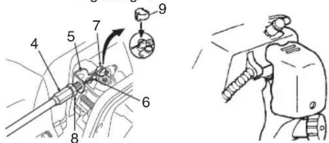
Fig. 6Fig. 5
natural_image
Technical line drawing of a mechanical device with no visible text or symbolsFig. 7
Fig. 13
natural_image
Line drawing of a hand using a tool to adjust or install a mechanical component (no text or symbols visible)Fig. 14
natural_image
Line drawing of a worker using a metal detector to measure a circular object (no text or symbols)Fig. 15
natural_image
Line drawing of a person in safety gear holding equipment (no text or symbols)Fig. 16
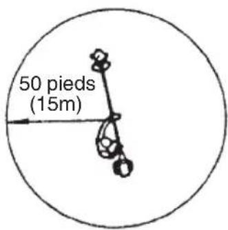
Fig. 17
ATTENTION
natural_image
Line drawing of a hand holding an internal combustion engine cylinder (no text or symbols)Fig. 21
Bougie (Fig. 22)
Fig. 22
REMARQUE
natural_image
Simple line drawing of a mechanical device with a lever and base mount (no text or symbols)Fig. 23
Entretien
Fig. 1
NOTA
natural_image
Mechanical diagram showing two configurations of a rotating device with lever and handle (no text or symbols)Fig. 2
natural_image
Illustration of two different automotive components with hoses and connectors, no text or symbols presentFig. 3 Fig. 4
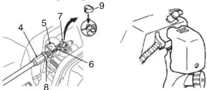
Fig. 6 Fig. 5
natural_image
Technical line drawing of a mechanical assembly with no visible text or symbolsFig. 7
Fig. 13
natural_image
Line drawing of a hand using a wrench to adjust or install a camera module (no text or symbols present)Fig. 14
Corte (Fig. 15, 16, 17)
natural_image
Illustration of a worker using a metal detector to measure a circular object, with arrows indicating motion (no text or symbols)Fig. 15
natural_image
Line drawing of a person in safety gear holding equipment (no text or symbols)Fig. 16
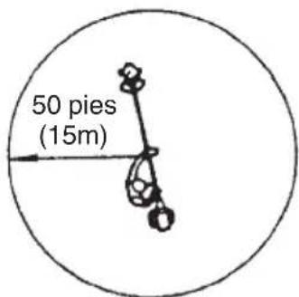
Fig. 17
ADVERTENCIA
natural_image
Line drawing of a hand holding an internal combustion engine cylinder (no text or symbols)Fig. 21
Bujía (Fig. 22)
Fig. 22
NOTA
natural_image
Simple line drawing of a mechanical device with a lever and base mount (no text or symbols)Fig. 23
natural_image
Line drawing of a quill pen in an inkwell (no text or symbols)
natural_image
Line drawing of a quill pen in an inkwell (no text or symbols)
natural_image
Line drawing of a quill pen in an inkwell (no text or symbols)WARNING:
Some dust created by power sanding, sawing, grinding, drilling, and other construction activities contains chemicals known to the State of California to cause cancer, birth defects or other reproductive harm.
Some examples of these chemicals are:
- Lead from lead-based paints,
- Crystalline silica from bricks and cement and other masonry products, and
- Arsenic and chromium from chemically-treated lumber.
Your risk from these exposures varies, depending on how often you do this type of work. To reduce your exposure to these chemicals: work in a well ventilated area, and work with approved safety equipment, such as those dust masks that are specially designed to filter out microscopic particles.
AVERTISSEMENT:
Minato-ku, Tokyo 108-6020, Japan
Distributed by

Hitachi Koki U.S.A., Ltd.
3950 Steve Reynolds Blvd.
Norcross, GA 30093

Hitachi Koki Canada Co.
450 Export Blvd. Unit B,
Mississauga ON L5T 2A4
- SAFETY INSTRUCTIONS AND INSTRUCTION MANUAL
- WARNING
- INSTRUCTIONS DE SECURITE ET MODE D'EMPLOI
- ⚠ AVERTISSEMENT
- Contents
- WHAT IS WHAT
- WARNINGS AND SAFETY INSTRUCTIONS
- Operator safety
- Unit/machine safety
- Fuel safety
- Cutting safety
- Maintenance safety
- Transport and storage
- CAUTION
- NOTE
- WARRANTY
- ASSEMBLY PROCEDURES
- Drive shaft to engine (Fig. 1)
- Installation of handle
- Throttle wire / stop cord
- Installation of blade guard (Fig. 7)
- Installation of cutting blade (Fig. 8)
- OPERATING PROCEDURES
- Fuel
- Fueling
- Starting
- Cutting (Fig. 15, 16, 17)
- Stopping (Fig. 18)
- Semi-auto cutting head
- MAINTENANCE
- Carburetor adjustment (Fig. 19)
- Idle speed adjustment (T-Screw)
- Air fi Iter (Fig. 20)
- Cleaning the air fi Iter
- Fuel fi Iter (Fig. 21)
- Spark plug (Fig. 22)
- Angle transmission (Fig. 23)
- Maintenance schedule
- Daily maintenance
- Weekly maintenance
- Monthly maintenance
- SIGNIFICATION DES SYMBOLES
- PRÉCAUTIONS ET CONSIGNES DE SÉCURITÉ
- REMARQUE
- ATTENTION
- Bougie (Fig. 22)
- Entretien
- NOTA
- Corte (Fig. 15, 16, 17)
- ADVERTENCIA
- Bujía (Fig. 22)
- WARNING:
- AVERTISSEMENT:
- Hitachi Koki U.S.A., Ltd.
- Hitachi Koki Canada Co.
Brand : HITACHI
Model : CG 24EKS(L)
Category : Hedge Trimmer