
SWH 55 A1 - Wall mount SILVERCREST - Free user manual and instructions
Find the device manual for free SWH 55 A1 SILVERCREST in PDF.


| Product type | Wall mount for flat screen |
| Brand | SilverCrest |
| Model | SWH 55 A1 |
| VESA standard | 400 x 400 mm (compatible with M4, M5, M6, M8 screws) |
| Maximum load capacity | 30 kg |
| Compatible screen diagonal | 81 to 140 cm (32 to 55 inches) |
| Wall distance | 66 to 340 mm |
| Tilt angle | -5° to 15° |
| Product weight | Approximately 4 kg |
| Mount material | Steel (not specified, estimate) |
| Compatible wall type | Solid concrete or wooden beams |
| Usage | Indoor only |
| Number of people required for installation | Minimum 2 |
| Required tools (not included) | Pencil, screwdriver, electric drill, tape measure |
| Package contents | Wall mount, TV plate, 5 mm hex key, magnetic bubble level, M5x30 safety screws (2x), mounting rails (2x), TV screw kit (M4, M5, M6, M8 x25mm – 4x each, spacer washers 4x, square washers 4x), wall screw kit (screws 4x, wall plugs 4x, washers 4x) |
| Maintenance | Clean with a damp cloth; check screw tightening every 2 months; check stability every 3 months |
| Safety distance around the load | At least 62 cm |
| Recycling | Packaging recyclable; used product to be disposed of at a recycling center |
Frequently Asked Questions - SWH 55 A1 SILVERCREST
User questions about SWH 55 A1 SILVERCREST
0 question about this device. Answer the ones you know or ask your own.
Ask a new question about this device
Download the instructions for your Wall mount in PDF format for free! Find your manual SWH 55 A1 - SILVERCREST and take your electronic device back in hand. On this page are published all the documents necessary for the use of your device. SWH 55 A1 by SILVERCREST.
USER MANUAL SWH 55 A1 SILVERCREST
TV-WANDHALTERUNG / TV WALL BRACKET / SUPPORT MURAL TV SWH 55 A1
DE AT CH
TV-WANDHALTERUNG
Assembly and safety advice
FR BE
SUPPORT MURAL TV
GB/IE Assembly and safety advice Page 10
natural_image
Diagram of two vertical metal structures with a central numbered connection (no text or symbols)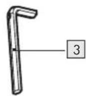
natural_image
Technical diagram of a mechanical assembly with two vertical components connected by a shaft (no text or symbols)Intended use Page 11
Warnings and symbols used Page 11
Safety instructions....Page 11
Description of parts....Page 12
Tools needed for assembly (not included). Page 13
Technical data Page 13
Before use.... Page 13
Assembly Page 13
Cleaning Page 16
Disposal Page 16
TV WALL BRACKET
Introduction
We congratulate you on the purchase of your new product. You have chosen a high quality product. The instructions for use are part of the product. They contain important information concerning safety, use and disposal. Before using the product, please familiarise yourself with all of the safety information and instructions for use. Only use the product as described and for the specified applications. If you pass the product on to anyone else, please ensure that you also pass on all the documentation with it.
- Intended use
This wall bracket is designed exclusively for wall mounting flat-panel displays with a screen diagonal of 32" to 55" on wood stud walls and solid concrete walls. This product may only be used privately and not for industrial or commercial purposes. Any other use is considered improper. Any claims resulting from improper use or due to unauthorised modification of the product will be considered un-warranted. Any such use is at your own risk.
● Warnings and symbols used
These instructions for use contain the following warnings:
DANGER!
This symbol with the signal word indicates a hazard with a high level of risk which, if not avoided, will result in serious injury or death.
WARNING!
This symbol with the signal word indicates a hazard with a medium level of risk which, if not avoided, could result in serious injury or death.
CAUTION!
This symbol with the signal word indicates a hazard with a low level of risk which, if not avoided, could result in minor or moderate injury.
NOTE:
This symbol with the signal word provides additional useful information.

Safety instructions
Before installing or using the product, please familiarize yourself with all of the safety instructions and instructions for use! When passing this product on to others, please also include all the documents!
⚠️ DANGER! DANGER TO LIFE AND RISK OF ACCIDENT FOR INFANTS AND CHILDREN!
⚠️ DANGER! RISK OF SUFFOCATION!
Never leave children unsupervised with the packaging material. The packaging material poses a suffocation hazard. Children frequently underestimate the dangers. The packaging material is not a toy.
This product contains small items that could be a choking hazard if swallowed. Keep these items away from young children.
Prior to installation / Preparation
- Do not install the product in places under which people might stand.
If you are unsure of any part of this installation, contact a professional installer for assistance.
⚠️ DANGER! Ensure that there are no electrical cables, water or gas pipes or other lines in the wall at the mounting location.
CAUTION! Check the suitability of the proposed wall for supporting the weight that is to be mounted. The wall must be capable of supporting the combined weight of the TV bracket as well as the TV set, otherwise the structure must be reinforced.
Never exceed the product's maximum load capacity of 30 kg (66 lbs) or else it may result in product failure or personal injury.
This product is intended for indoor use only. Use of this product outdoors could lead to product failure or personal injury.
Installation
■ Safety gear and proper tools must be used. A minimum of 2 people are required for this installation.
■ Never use violence or excessive force for assembly. This could damage your TV set or the product.
■ After mounting the product, check its stability and operational reliability as well as that of the mounted load.
Use
- Maintain a safe distance of at least 62 cm around the mounted load. - In the case of damage, remove the mounted load and stop using the product.
Maintenance
- Check joint parts every 2 months to ensure that no screws have loosened.
- Check the product's stability and operational reliability as well as that of the mounted load at regular intervals (at least every 3 months).
NOTES:
- Bearing in mind the wide variety of TV sets and wall mountings available on the market, the supplied mounting kit may not cover all the possibilities.
In rare cases, it is possible that the screws for attaching the TV set may be too long. If this is the case, use the supplied extension washers.
If the mounting material necessary for your set is not provided in the supplied mounting kit, please purchase the items you require from a specialist shop.
If your wall is made of different types of materials and construction than that intended for the installation, purchase suitable materials from a specialist shop.
● Description of parts
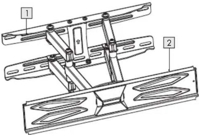
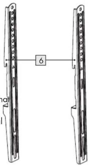
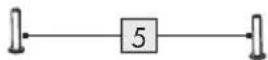
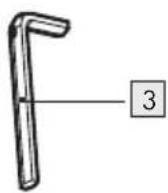
1 Wall bracket
2 TV plate
√3 Hex key 5 x 5 mm
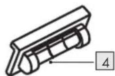
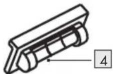
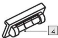
4 Magnetic removable spirit level
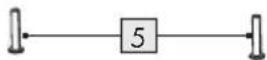
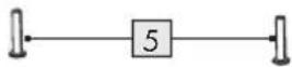
5 Safety screw M5 x 30 mm (2x)
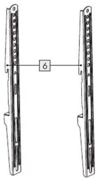
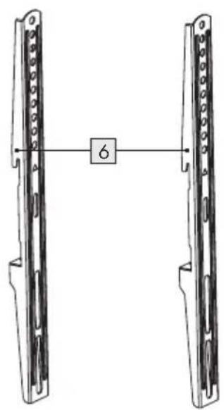
6 Mounting rails (2x)
TV attachment screw set
| 7 | Screw M4 x 25 mm | (4x) | |
| 8 | Screw M5 x 25 mm | (4x) | |
| 9 | Screw M6 x 25 mm | (4x) | |
| 10 | Screw M8 x 25 mm | (4x) | |
| 11 | Extension washer | (4x) | |
| 12 | Square washer | (4x) |
Wall mounting screw set
| 13 | Screw | (4x) |
| 14 | Wall plug | (4x) |
| 15 | Washer | (4x) |
● Tools needed for assembly (not included)
Pencil
Screwdriver
Electric drill
Measuring tape
● Technical data
VESA standard: 400 x 400 mm
| Max. loading capacity: 30 kg (66 lbs) | |
| Screen diagonal of flat-panel display: | 81 to 140 cm(32" to 55") |
| Wall clearance to the back of the TV set: | 66 to 340 mm(2.6" to 13.4") |
| Tilt angle: -5° to 15° | |
Product weight (approx.): 4 kg (8.8 lbs)
The specification and design may be changed without notification.
Before use
NOTES:
All parts have to be unpacked and the packaging material has to be removed completely.
■ Before use, verify the package contents are complete and undamaged!
Assembly
Assembly step 1
OPTION 1: Mounting on solid concrete
■ Select a suitable mounting height. The ideal height for a TV set is parallel to the eye-level of a seated person.
- Hold the wall bracket to the desired position on the wall and align it with the spirit level 4. Mark the 4 holes with a pencil.
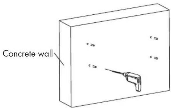
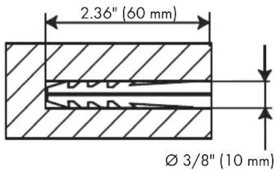
- Drill holes at the marked positions with a diameter of 10 mm and a depth of 60 mm.
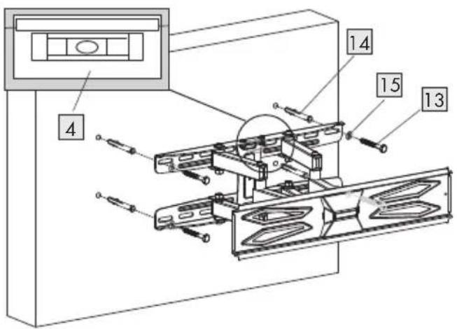
- Insert the wall plug into the holes. Screw the wall bracket to the wall using the supplied screws 13 and the washers 15.
OPTION 2: Mounting on wood studs
- Identify where the studs in your wall are.
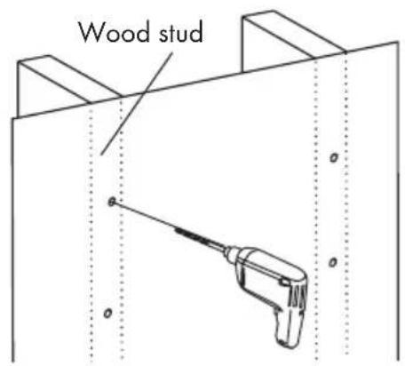
- Hold the wall bracket to the desired position on the wall and align it with the spirit level 4. Mark the 4 holes on the studs using a pencil.
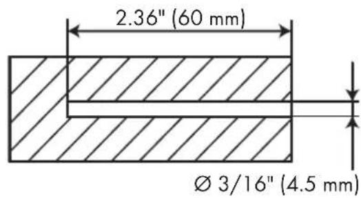
- Drill holes at the marked positions with a diameter of 4.5 mm and a depth of 60 mm.
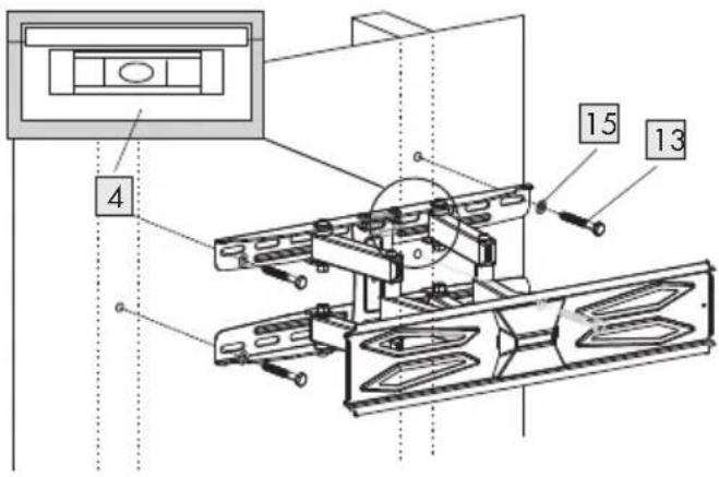
- Screw the wall bracket to the wall using the supplied screws 13 and the washers 15.
Assembly step 2
- Check whether the supplied screws, \$8, 9 or 10) fit in the prepared holes on the back of your TV set. If this is not the case, use other suitable screws and washers.
The square washer consists of 3 holes for different size of screws.
Square washer 12
Large hole M8 screws
Medium hole M5 or M6 screws
Small hole M4 screws
OPTION 1: Attaching mounting rails to your TV set
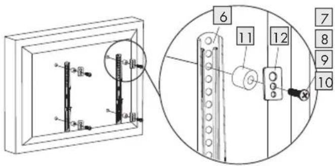
- Attach the mounting fails the back of your TV set.
Screw the mounting candle using the suitable screws 7, 8, 9 or 10 (depending on the size of the holes) and square washers 12.
NOTE:
If the screws 8, 9 or 10 are too long for the mounting holes, use the extension washers 11 between the mounting rails 6 and the square washers 12.
OPTION 2: For TV sets with a curved rear panel
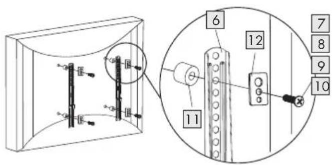
If the screws 8, 9 or 10 are too long for the mounting holes, use the extension washers 11 between the mounting rails 6 and the TV set.
Assembly step 3
Hanging the TV set on the TV plate
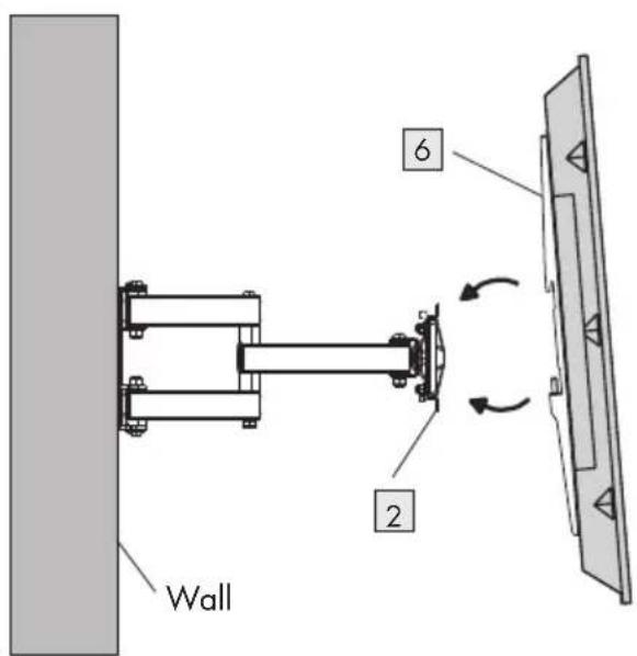
- Attach the mounting coil attached on the TV set) on the TV plate 2.
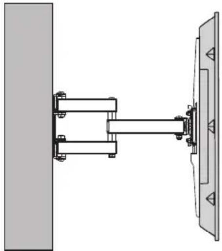
natural_image
Technical diagram of a mechanical assembly with two vertical components connected by a shaft (no text or symbols)- Tighten the safety screw at the bottom to secure the TV set to the TV plate 2.
Setting the optimum tilting position
The vertical tilt angle can be set between -5^ and 15^ (depending on the TV set).
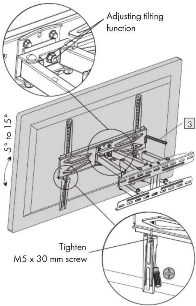
■ Align the TV set as desired. Then, tighten or loosen the screw nuts M6 on the head of the wall plate to adjust the tilting function.
Cleaning
- Do not use any aggressive or abrasive cleaning agents, as these may damage the surface of the wall bracket. - Clean the product using a moistened cloth and a standard commercial household cleaning fluid.
- Disposal
The packaging is made of environmentally friendly materials, which may be disposed of through your local recycling facilities.
Contact your municipality for information on how to dispose of your worn-out product.
Introduction Page 18
natural_image
Diagram of two vertical metal structures with a central labeled component '6' connected by a line (no text or symbols beyond the number)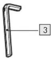
natural_image
Technical diagram of a mechanical assembly with two vertical components connected by a shaft (no text or symbols)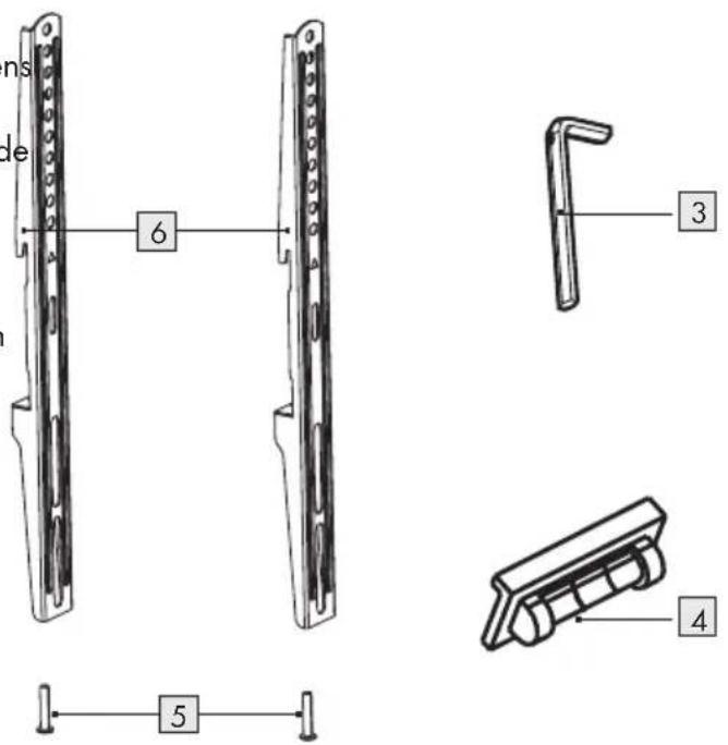
1 Muurbeugel
2 TV-plaat
3 Inbussleutel 5 x 5 mm
4 Afneembare magnetische waterpas
natural_image
Technical diagram of a mechanical assembly with two vertical components connected by a shaft (no text or symbols)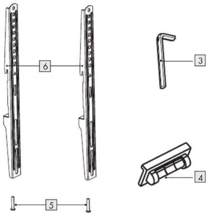
natural_image
Technical diagram of a mechanical assembly with two vertical components connected by a rod (no text or symbols present)- TV-WANDHALTERUNG / TV WALL BRACKET / SUPPORT MURAL TV SWH 55 A1
- TV-WANDHALTERUNG
- SUPPORT MURAL TV
- TV WALL BRACKET
- Introduction
- - Intended use
- ● Warnings and symbols used
- DANGER!
- WARNING!
- CAUTION!
- NOTE:
- Safety instructions
- ⚠️ DANGER! DANGER TO LIFE AND RISK OF ACCIDENT FOR INFANTS AND CHILDREN!
- ⚠️ DANGER! RISK OF SUFFOCATION!
- Prior to installation / Preparation
- Installation
- Use
- Maintenance
- NOTES:
- ● Tools needed for assembly (not included)
- ● Technical data
- Before use
- Assembly
- Assembly step 1
- OPTION 1: Mounting on solid concrete
- OPTION 2: Mounting on wood studs
- Assembly step 2
- Square washer 12
- OPTION 1: Attaching mounting rails to your TV set
- Assembly step 3
- Setting the optimum tilting position
- Cleaning
- - Disposal
Brand : SILVERCREST
Model : SWH 55 A1
Category : Wall mount