
LT10A - Loudspeaker Proel - Free user manual and instructions
Find the device manual for free LT10A Proel in PDF.


| Type | Active 2-way vented PA speaker |
| Woofer | 10" (254 mm) with 2" voice coil |
| Tweeter | 1" (25 mm) neodymium compression driver, 1" VC |
| Total Peak Power | 600 W |
| LF Amplifier Power | 250 W Class D |
| HF Amplifier Power | 50 W Class AB |
| Frequency Response (-10 dB) | 60 Hz – 20 kHz |
| Max SPL at 1 m (peak) | 123 dB |
| Coverage Angle | 90° H x 60° V |
| Crossover Frequency | 2 kHz |
| Input Sensitivity | Line: +4 dBu / Mic: -20 dBu |
| Input Impedance | 30 kΩ balanced, 15 kΩ unbalanced |
| Input Connectors | Combo XLR-F / Jack (Mic/Line), Link XLR-M |
| Controls | MIC/LINE, LEVEL, LOW, HIGH, GND LIFT |
| Power Supply | SMPS, selectable 115V/230V, 50/60 Hz |
| Rated Power Consumption | 300 W |
| Cabinet Material | Plywood with black scratch-resistant paint |
| Grille | Steel with internal foam layer |
| Flying System | 4 x M10 threaded inserts (top/bottom) |
| Pole Mount | Dual-angle pole holder (bottom) |
| Handles | 1 rear |
| Weight | 12.5 kg (27.6 lb) |
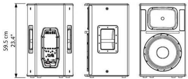
| Dimensions (W x H x D) | 340 x 515 x 310 mm |
| Protection | Thermal, over-power limiter, clip limiter |
| Cleaning | Clean only with dry cloth; check ventilation slots periodically |
Frequently Asked Questions - LT10A Proel
User questions about LT10A Proel
0 question about this device. Answer the ones you know or ask your own.
Ask a new question about this device
Download the instructions for your Loudspeaker in PDF format for free! Find your manual LT10A - Proel and take your electronic device back in hand. On this page are published all the documents necessary for the use of your device. LT10A by Proel.
USER MANUAL LT10A Proel
natural_image
Line drawing of six different industrial storage units arranged in ascending order (no text or symbols)FCC COMPLIANCE NOTICE
This device complies with part 15 of the FCC rules. Operation is subject to the following two conditions:
(1) This device may not cause harmful interference, and
(2) this device must accept any interference received, including interference that may cause undesired operation.
CAUTION: Changes or modifications not expressly approved by the party responsible for compliance could void the user's authority to operate the equipment.
NOTE: This equipment has been tested and found to comply with the limits for a Class B digital device, pursuant to part 15 of the FCC Rules. These limits are designed to provide reasonable protection against harmful interference in a residential installation. This equipment generates, uses, and can radiate radio frequency energy and, if not installed and used in accordance with the instruction manual, may cause harmful interference to radio communications. However, there is no guarantee that interference will not occur in a particular installation. If this equipment does cause harmful interference to radio or television reception, which can be determined by turning the equipment off and on, the user is encouraged to try to correct the interference by one or more of the following measures:
- Reorient or relocate the receiving antenna.
- Increase the separati on between the equipment and receiver.
- Connect the equipment into an outlet on a circuit different from that to which the receiver is connected.
- Consult the dealer or an experienced radio/TV technician for help.
This marking shown on the product or its literature, indicates that it should not be disposed with other household wastes at the end of its working life. To prevent possible harm to the environment or human health from uncontrolled waste disposal, please separate this from other types of wastes and recycle it responsibly to promote the sustainable reuse of material resources. Household users should contact either the retailer where they purchased this product, or their local government office, for details of where and how they can take this item for environmentally safe recycling. Business users should contact their supplier and check the terms and conditions of the
purchase contract. This product should not be mixed with other commercial wastes for disposal.

The lightning flash with arrowhead symbol within an equilateral triangle is intended to alert the user to the presence of uninsulated "dangerous voltage" within the product's enclosure, that may be of sufficient magnitude to constitute a risk of electric shock to persons.

The exclamation point within an equilateral triangle is intended to alert the user to the presence of important operating and maintenance (servicing) instructions in the literature accompanying the appliance.
The information contained in this publication has been carefully prepared and checked. However no responsibility will be taken for any errors. All rights are reserved and this document cannot be copied, photocopied or reproduced in part or completely without written consent being obtained in advance from PROEL. PROEL reserves the right to make any aesthetic, functional or design modification to any of its products without any prior notice. PROEL assumes no responsibility for the use or application of the products or circuits described herein.
DIMENSIONS AND FLYING POINTS ..... 5
ACCESSORIES 7
LT6A CONTROL PANEL (FIG.1) 8
LT8A CONTROL PANEL (FIG.2) 9
LT10A / LT12A / LT15A / LT215A
CONTROL PANEL (FIG.3) 10
CONNECTIONS (FIG.4)....10
CONFIGURATIONS (FIG.5) 11
SAFETY AND PRECAUTIONS....12
IN CASE OF FAULT 12
TROUBLESHOOTING....12
CE CONFORMITY 13
PACKAGING, SHIPPING AND COMPLAINT ..... 13
WARRANTY AND PRODUCTS RETURN ..... 13
INSTALLATION AND DISCLAIMER....13
POWER SUPPLY AND MAINTENANCE ..... 13
GENERAL INFORMATION....14
INSTRUCTIONS (FIG. 1 / 2 / 3 / 4 / 5) ..... 14
INDICE
| System type | 2-way vented enclosure | 2-way vented enclosure | 2-way vented enclosure | 2-way vented enclosure | 2-way vented enclosure | 2-way vented enclosure |
| High Frequency Device | 1" neodymium tweeter | 1" compression driver 1" VC | 1" compression driver 1.35" VC | 1" compression driver 1.35" VC | 1" compression driver 1.35" VC | 1" compression driver 1.35" VC |
| Low Frequency Device | 6.5" woofer with 1" VC | 8" woofer with 1.5" VC | 10" woofer with 2" VC | 12" woofer with 2.5" VC | 15" woofer with 2.5" VC | 2x 15" woofer with 2.5" VC |
| Angular Coverage | 60° H x 40° V | 60° H x 40° V | 90° H x 60° V | 90° H x 60° V | 90° H x 60° V | 90° H x 60° V |
| Total peak power | 150 W | 400 W | 600 W | 600 W | 600 W | 1200 W |
| HF Amplifier Power | 50 W Class D | 50 W Class AB | 50 W Class AB | 50 W Class AB | 100 W Class AB | |
| LF Amplifier Power | 75 W Class AB | 150 W Class D | 250 W Class D | 250 W Class D | 250 W Class D | 500 W Class D |
| Power Supply type | LINEAR | SMPS | SMPS | SMPS | SMPS | SMPS |
| Frequency Response | 75 Hz - 20 kHz | 70 Hz - 20 kHz | 60 Hz - 20 kHz | 50 Hz - 20 kHz | 45 Hz - 20 kHz | 45 Hz - 20 kHz |
| Processing | Analog | Analog | Analog | Analog | Analog | Analog |
| Max SPL at 1mt (peak) | 110 dBspl | 121 dBspl | 123 dBspl | 124 dBspl | 126 dBspl | 132 dBspl |
| Crossover Frequency | 2400 Hz | 2200 Hz | 2000 Hz | 2000 Hz | 2000 Hz | 2000 Hz |
| Input Impedance | 30 kohm balanced 15 kohm unbalanced | 30 kohm balanced 15 kohm unbalanced | 30 kohm balanced 15 kohm unbalanced | 30 kohm balanced 15 kohm unbalanced | 30 kohm balanced 15 kohm unbalanced | 30 kohm balanced 15 kohm unbalanced |
| Input Sensitivity | LINE: 0/-10 dBu / MIC: -20 dBu | LINE: +4 dBu / MIC: -20 dBu | LINE: +4 dBu / MIC: -20 dBu | LINE: +4 dBu / MIC: -20 dBu | LINE: +4 dBu / MIC: -20 dBu | LINE: +4 dBu / MIC: -20 dBu |
| Controls | MIC/LINE, LEVEL | MIC/LINE, LEVEL, LOW, HIGH, GND. | MIC/LINE, LEVEL, LOW, HIGH, GND. | MIC/LINE, LEVEL, LOW, HIGH, GND. | MIC/LINE, LEVEL, LOW, HIGH, GND. | MIC/LINE, LEVEL, LOW, HIGH, GND. |
| Connectors | MIC/LINE: Combo XLR-F / JACK, LINE: RCA, LINK: XLR-M | MIC/LINE: Combo XLR-F / JACK LINK: XLR-M | MIC/LINE: Combo XLR-F / JACK LINK: XLR-M | MIC/LINE: Combo XLR-F / JACK LINK: XLR-M | MIC/LINE: Combo XLR-F / JACK LINK: XLR-M | MIC/LINE: Combo XLR-F / JACK LINK: XLR-M |
| Power Supply | 230 V~ or 120 V~- 50/60 Hz | 230 V~ or 120 V~- 50/60 Hz | 230 V~ or 120 V~- 50/60 Hz | 230 V~ or 120 V~- 50/60 Hz | 230 V~ or 120 V~- 50/60 Hz | 230 V~ or 120 V~- 50/60Hz |
| Rated Consumption | 100 W | 150 W | 300 W | 300 W | 300 W | 700 W |
| Construction | Plywood | Plywood | Plywood | Plywood | Plywood | Plywood |
| Cabinet Colour | Black | Black | Black | Black | Black | Black |
| Flying System | 1 x M4 top / 2 x M4 bottom | 4 x M8 top/bottom | 4 x M10 top/bottom | 4 x M10 top/bottom | 4 x M10 top/bottom | 4 x M10 top/bottom |
| Handles | - | 1 x rear | 1 x rear | 2 x sides | 2 x sides | 2 x sides, 1 x top |
| Mounting Pole | 1 x bottom | 1 x bottom, dual angle | 1 x bottom, dual angle | 1 x bottom, dual angle | 1 x bottom, dual angle | 1 x bottom |
| Weight | 5.9 kg (13 lb) | 8.5 kg (18.7 lb) | 12.5 kg (27.6 lb) | 16.5 kg (36.4 lb) | 21 kg (46.3 lb) | 34 kg (74.9 lb) |
| Dimensions (W x H x D) | 204 x 295 x 223 mm | 220 x 442 x 260 mm | 340 x 515 x 310 mm | 380 x 595 x 360 mm | 448 x 670 x 410 mm | 448 x 1060 x 450 mm |
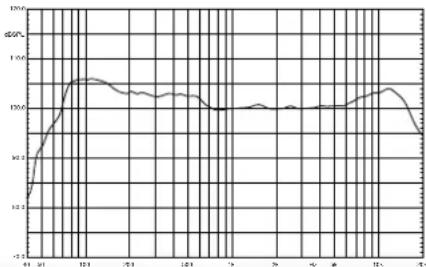
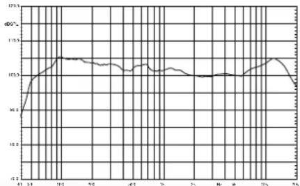
FREQUENCY RESPONSE RISPOSTA IN FREQUENZA
LT6A

line
| Date | Value | |---|---| | 01-01 | 10.5 | | 02-01 | 11.0 | | 03-01 | 11.5 | | 04-01 | 12.0 | | 05-01 | 12.2 | | 06-01 | 12.1 | | 07-01 | 12.0 | | 08-01 | 11.9 | | 09-01 | 11.8 | | 10-01 | 11.7 | | 11-01 | 11.6 | | 12-01 | 11.5 | | 13-01 | 11.4 | | 14-01 | 11.3 | | 15-01 | 11.2 | | 16-01 | 11.1 | | 17-01 | 11.0 | | 18-01 | 10.9 | | 19-01 | 10.8 | | 20-01 | 10.7 | | 21-01 | 10.6 | | 22-01 | 10.5 | | 23-01 | 10.4 | | 24-01 | 10.3 | | 25-01 | 10.2 | | 26-01 | 10.1 | | 27-01 | 10.0 | | 28-01 | 9.9 | | 29-01 | 9.8 | | 30-01 | 9.7 | | 31-01 | 9.6 | | 32-01 | 9.5 | | 33-01 | 9.4 | | 34-01 | 9.3 | | 35-01 | 9.2 | | 36-01 | 9.1 | | 37-01 | 9.0 | | 38-01 | 8.9 | | 39-01 | 8.8 | | 40-01 | 8.7 | | 41-01 | 8.6 | | 42-01 | 8.5 | | 43-01 | 8.4 | | 44-01 | 8.3 | | 45-01 | 8.2 | | 46-01 | 8.1 | | 47-01 | 8.0 | | 48-01 | 7.9 | | 49-01 | 7.8 | | 50-01 | 7.7 | | 51-01 | 7.6 | | 52-01 | 7.5 | | 53-01 | 7.4 | | 54-01 | 7.3 | | 55-01 | 7.2 | | 56-01 | 7.1 | | 57-01 | 7.0 | | 58-01 | 6.9 | | 59-01 | 6.8 | | 60-01 | 6.7 | | 61-01 | 6.6 | | 62-01 | 6.5 | | 63-01 | 6.4 | | 64-01 | 6.3 | | 65-01 | 6.2 | | 66-01 | 6.1 | | 67-01 | 6.0 | | 68-01 | 5.9 | | 69-01 | 5.8 | | 70-01 | 5.7 | | 71-01 | 5.6 | | 72-01 | 5.5 | | 73-01 | 5.4 | | 74-01 | 5.3 | | 75-01 | 5.2 | | 76-01 | 5.1 | | 77-01 | 5.0 | | 78-01 | 4.9 | | 79-01 | 4.8 | | 80-01 | 4.7 | | 81-01 | 4.6 | | 82-01 | 4.5 | | 83-01 | 4.4 | | 84-01 | 4.3 | | 85-01 | 4.2 | | 86-01 | 4.1 | | 87-01 | 4.0 | | 88-01 | 3.9 | | 89-01 | 3.8 | | 90-01 | 3.7 | | 91-01 | 3.6 | | 92-01 | 3.5 | | 93-01 | 3.4 | | 94-01 | 3.3 | | 95-01 | 3.2 | | 96-01 | 3.1 | | 97-01 | 3.0 | | 98-01 | 2.9 | | 99-01 | 2.8 | | N/A | - |LT8A

line
| Date | φG (%) | |---|---| | 4/13 | 10.7 | | 5/13 | 12.0 | | 10/13 | 13.8 | | 11/13 | 13.6 | | 12/13 | 13.4 | | 01/03 | 13.4 | | 02/03 | 13.4 | | 03/03 | 13.4 | | 04/03 | 13.4 | | 05/03 | 13.4 | | 06/03 | 13.4 | | 07/03 | 13.4 | | 08/03 | 13.4 | | 09/03 | 13.4 | | 10/03 | 13.4 | | 11/03 | 13.4 | | 12/03 | 13.4 | | 1/04 | 13.4 | | 2/04 | 13.4 | | 3/04 | 13.4 | | 4/04 | 13.4 | | 5/04 | 13.4 | | 6/04 | 13.4 | | 7/04 | 13.4 | | 8/04 | 13.4 | | 9/04 | 13.4 | | 10/04 | 13.4 | | 11/04 | 13.4 | | 12/04 | 13.4 | | 1/05 | 13.4 | | 2/05 | 13.4 | | 3/05 | 13.4 | | 4/05 | 13.4 | | 5/05 | 13.4 | | 6/05 | 13.4 | | 7/05 | 13.4 | | 8/05 | 13.4 | | 9/05 | 13.4 | | 10/05 | 13.4 | | 11/05 | 13.4 | | 12/05 | 13.4 | | 1/06 | 13.4 | | 2/06 | 13.4 | | 3/06 | 13.4 | | 4/06 | 13.4 | | 5/06 | 13.4 | | 6/06 | 13.4 | | 7/06 | 13.4 | | 8/06 | 13.4 | | 9/06 | 13.4 | | 10/06 | 13.4 | | 11/06 | 13.4 | | 12/06 | 13.4 | | 1/07 | 13.4 | | 2/07 | 13.4 | | 3/07 | 13.4 | | 4/07 | 13.4 | | 5/07 | 13.4 | | 6/07 | 13.4 | | 7/07 | 13.4 | | 8/07 | 13.4 | | 9/07 | 13.4 | | 10/07 | 13.4 | | 11/07 | 13.4 | | 12/07 | 13.4 | | 1/08 | 13.4 | | 2/08 | 13.4 | | 3/08 | 13.4 | | 4/08 | 13.4 | | 5/08 | 13.4 | | 6/08 | 13.4 | | 7/08 | 13.4 | | 8/08 | 13.4 | | 9/08 | 13.4 | | 10/08 | 13.4 | | 11/08 | 13.4 | | 12/08 | 13.4 | | -2/08 | -2.9 | | -2/09 | -2.9 | | -2/10 | -2.9 | | -2/11 | -2.9 | | -2/12 | -2.9 | | -2/13 | -2.9 | | -2/14 | -2.9 | | -2/15 | -2.9 | | -2/16 | -2.9 | | -2/17 | -2.9 | | -2/18 | -2.9 | | -2/19 | -2.9 | | -2/20 | -2.9 | | -2/21 | -2.9 | | -2/22 | -2.9 | | -2/23 | -2.9 | | -2/24 | -2.9 | | -2/25 | -2.9 | | -2/26 | -2.9 | | -2/27 | -2.9 | | -2/28 | -2.9 | | -2/29 | -2.9 | | -2/30 | -2.9 | | -2/31 | -2.9 | | -3/01 | -2.9 | | -3/02 | -2.9 | | -3/03 | -2.9 | | -3/04 | -2.9 | | -3/05 | -2.9 | | -3/06 | -2.9 | | -3/07 | -2.9 | | -3/08 | -2.9 | | -3/09 | -2.9 | | -3/10 | -2.9 | | -3/11 | -2.9 | | -3/12 | -2.9 | | -3/13 | -2.9 | | -3/14 | -2.9 | | -3/15 | -2.9 | | -3/16 | -2.9 | | -3/17 | -2.9 | | -3/18 | -2.9 | | -3/19 | -2.9 | | -3/20 | -2.9 | | -3/21 | -2.9 | | -3/22 | -2.9 | | -3/23 | -2.9 | | -3/24 | -2.9 | | -3/25 | -2.9 | | -3/26 | -2.9 | | -3/27 | -2.9 | | -3/28 | -2.9 | | -3/29 | -2.9 | | -3/30 | -2.9 | | -4/01 | -2.9 | | -4/02 | -2.9 | | -4/03 | -2.9 | | -4/04 | -2.9 | | -4/05 | -2.9 | | -4/06 | -2.9 | | -4/07 | -2.9 | | -4/08 | -2.9 | | -4/09 | -2.9 | | -4/10 | -2.9 | | -4/11 | -2.9 | | -4/12 | -2.9 | | -4/13 | -2.9 | | -4/14 | -2.9 | | -4/15 | -2.9 | | -4/16 | -2.9 | | -4/17 | -2.9 | | -4/18 | -2.9 | | -4/19 | -2.9 | | -4/20 | -2.9 | | -4/21 | -2.9 | | -4/22 | -2.9 | | -4/23 | -2.9 | | -4/24 | -2.9 | | -4/25 | -2.9 | | -4/26 | -2.9 | | -4 /LT10A

line
| Date | Value | |---|---| | 12 | 10.1 | | 13 | 12.8 | | 14 | 12.9 | | 15 | 12.7 | | 16 | 12.6 | | 17 | 12.5 | | 18 | 12.4 | | 19 | 12.3 | | 20 | 12.2 | | 21 | 12.1 | | 22 | 12.0 | | 23 | 12.0 | | 24 | 12.0 | | 25 | 12.0 | | 26 | 12.0 | | 27 | 12.0 | | 28 | 12.0 | | 29 | 12.0 | | 30 | 12.0 | | 31 | 12.0 | | 32 | 12.0 | | 33 | 12.0 | | 34 | 12.0 | | 35 | 12.0 | | 36 | 12.0 | | 37 | 12.0 | | 38 | 12.0 | | 39 | 12.0 | | 40 | 12.0 | | 41 | 12.0 | | 42 | 12.0 | | 43 | 12.0 | | 44 | 12.0 | | 45 | 12.0 | | 46 | 12.0 | | 47 | 12.0 | | 48 | 12.0 | | 49 | 12.0 | | 50 | 12.0 | | 51 | 12.0 | | 52 | 12.0 | | 53 | 12.0 | | 54 | 12.0 | | 55 | 12.0 | | 56 | 12.0 | | 57 | 12.0 | | 58 | 12.0 | | 59 | 12.0 | | 60 | 12.0 | | 61 | 12.0 | | 62 | 12.0 | | 63 | 12.0 | | 64 | 12.0 | | 65 | 12.0 | | 66 | 12.0 | | 67 | 12.0 | | 68 | 12.0 | | 69 | 12.0 | | 70 | 12.0 | | 71 | 12.0 | | 72 | 12.0 | | 73 | 12.0 | | 74 | 12.0 | | 75 | 12.0 | | 76 | 12.0 | | 77 | 12.0 | | 78 | 12.0 | | 79 | 12.0 | | 80 | 12.0 | | 81 | 12.0 | | 82 | 12.0 | | 83 | 12.0 | | 84 | 12.0 | | 85 | 12.0 | | 86 | 12.0 | | 87 | 12.0 | | 88 | 12.0 | | 89 | 12.0 | | 90 | 12.0 | | 91 | 12.0 | | 92 | 12.0 | | 93 | 12.0 | | 94 | 12.0 | | 95 | 12.0 | | 96 | 12.0 | | 97 | 12.0 | | 98 | 12.0 | | 99 | 12.0 | | N/A | -125.5 |LT12A
line
| X-Axis | Y-Axis | |---|---| | 41 | 12.0 | | 39 | 13.0 | | 38 | 14.0 | | 37 | 14.5 | | 36 | 14.2 | | 35 | 14.0 | | 34 | 13.8 | | 33 | 13.6 | | 32 | 13.5 | | 31 | 13.4 | | 30 | 13.3 | | 29 | 13.2 | | 28 | 13.1 | | 27 | 13.0 | | 26 | 12.9 | | 25 | 12.8 | | 24 | 12.7 | | 23 | 12.6 | | 22 | 12.5 | | 21 | 12.4 | | 20 | 12.3 | | 19 | 12.2 | | 18 | 12.1 | | 17 | 12.0 | | 16 | 11.9 | | 15 | 11.8 | | 14 | 11.7 | | 13 | 11.6 | | 12 | 11.5 | | 11 | 11.4 | | 10 | 11.3 | | 9 | 11.2 | | 8 | 11.1 | | 7 | 11.0 | | 6 | 10.9 | | 5 | 10.8 | | 4 | 10.7 | | 3 | 10.6 | | 2 | 10.5 | | 1 | 10.4 | | 0 | 10.3 | | -1 | 10.2 | | -2 | 10.1 | | -3 | 10.0 | | -4 | 9.9 | | -5 | 9.8 | | -6 | 9.7 | | -7 | 9.6 | | -8 | 9.5 | | -9 | 9.4 | | -10 | 9.3 | | -11 | 9.2 | | -12 | 9.1 | | -13 | 9.0 | | -14 | 8.9 | | -15 | 8.8 | | -16 | 8.7 | | -17 | 8.6 | | -18 | 8.5 | | -19 | 8.4 | | -20 | 8.3 | | -21 | 8.2 | | -22 | 8.1 | | -23 | 8.0 | | -24 | 7.9 | | -25 | 7.8 | | -26 | 7.7 | | -27 | 7.6 | | -28 | 7.5 | | -29 | 7.4 | | -30 | 7.3 | | -31 | 7.2 | | -32 | 7.1 | | -33 | 7.0 | | -34 | 6.9 | | -35 | 6.8 | | -36 | 6.7 | | -37 | 6.6 | | -38 | 6.5 | | -39 | 6.4 | | -40 | 6.3 | | -41 | 6.2 | | -42 | 6.1 | | -43 | 6.0 | | -44 | 5.9 | | -45 | 5.8 | | -46 | 5.7 | | -47 | 5.6 | | -48 | 5.5 | | -49 | 5.4 | | -50 | 5.3 | | -51 | 5.2 | | -52 | 5.1 | | -53 | 5.0 | | -54 | 4.9 | | -55 | 4.8 | | -56 | 4.7 | | -57 | 4.6 | | -58 | 4.5 | | -59 | 4.4 | | -60 | 4.3 | | -61 | 4.2 | | -62 | 4.1 | | -63 | 4.0 | | -64 | 3.9 | | -65 | 3.8 | | -66 | 3.7 | | -67 | 3.6 | | -68 | 3.5 | | -69 | 3.4 | | -70 | 3.3 | | -71 | 3.2 | | -72 | 3.1 | | -73 | 3.0 | | -74 | 2.9 | | -75 | 2.8 | | -76 | 2.7 | | -77 | 2.6 | | -78 | 2.5 | | -79 | 2.4 | | -80 | 2.3 | | -81 | 2.2 | | -82 | 2.1 | | -83 | 2.0 | | -84 | 1.9 | | -85 | 1.8 | | -86 | 1.7 | | -87 | 1.6 | | -88 | 1.5 | | -89 | 1.4 | | -90 | 1.3 | | -91 | 1.2 | | -92 | 1.1 | | -93 | 1.0 | | -94 | 0.9 | | -95 | 0.8 | | -96 | 0.7 | | -97 | 0.6 | | -98 | 0.5 | | -99 | 0.4 | | -100 | 0.3 | The chart displays a single data series (likely 'Y' or similar) plotted against an unlabeled horizontal axis (X). The Y-axis is labeled 'Y' and the X-axis is labeled 'X'. The data series are represented by a single line connecting the points of the line on the horizontal axis, with labels above and below the lines.LT15A
line
| Date | Value | | ---- | ----- | | 01 | 14.2 | | 02 | 15.8 | | 03 | 16.5 | | 04 | 16.2 | | 05 | 16.0 | | 06 | 15.8 | | 07 | 15.5 | | 08 | 15.3 | | 09 | 15.2 | | 10 | 15.4 | | 11 | 15.6 | | 12 | 15.8 | | 13 | 16.0 | | 14 | 16.2 | | 15 | 16.5 | | 16 | 16.8 | | 17 | 17.0 | | 18 | 16.8 | | 19 | 16.5 | | 20 | 16.2 | | 21 | 15.8 | | 22 | 15.5 | | 23 | 15.2 | | 24 | 15.0 | | 25 | 14.8 | | 26 | 14.5 | | 27 | 14.2 | | 28 | 14.0 | | 29 | 13.8 | | 30 | 13.5 | | 31 | 13.2 | | 32 | 13.0 | | 33 | 12.8 | | 34 | 12.5 | | 35 | 12.2 | | 36 | 12.0 | | 37 | 11.8 | | 38 | 11.5 | | 39 | 11.2 | | 40 | 11.0 | | 41 | 10.8 | | 42 | 10.5 | | 43 | 10.2 | | 44 | 10.0 | | 45 | 9.8 | | 46 | 9.5 | | 47 | 9.2 | | 48 | 9.0 | | 49 | 8.8 | | 50 | 8.5 | | 51 | 8.2 | | 52 | 8.0 | | 53 | 7.8 | | 54 | 7.5 | | 55 | 7.2 | | 56 | 7.0 | | 57 | 6.8 | | 58 | 6.5 | | 59 | 6.2 | | 60 | 6.0 | | 61 | 5.8 | | 62 | 5.5 | | 63 | 5.2 | | 64 | 5.0 | | 65 | 4.8 | | 66 | 4.5 | | 67 | 4.2 | | 68 | 4.0 | | 69 | 3.8 | | 70 | 3.5 | | 71 | 3.2 | | 72 | 3.0 | | 73 | 2.8 | | 74 | 2.5 | | 75 | 2.2 | | 76 | 2.0 | | 77 | 1.8 | | 78 | 1.5 | | 79 | 1.2 | | 80 | 1.0 | | 81 | -0.2 | | 82 | -0.5 | | 83 | -0.8 | | 84 | -1.0 | | 85 | -1.2 | | 86 | -1.5 | | 87 | -1.8 | | 88 | -2.0 | | 89 | -2.2 | | 90 | -2.5 | | 91 | -2.8 | | 92 | -3.0 | | 93 | -3.2 | | 94 | -3.5 | | 95 | -3.8 | | 96 | -4.0 |LT215A

line
| X-Axis | Y-Axis | |---|---| | 1 | 10.0 | | 2 | 10.5 | | 3 | 11.0 | | 4 | 11.5 | | 5 | 11.8 | | 6 | 11.6 | | 7 | 11.4 | | 8 | 11.2 | | 9 | 11.0 | | 10 | 10.8 | | 11 | 10.6 | | 12 | 10.4 | | 13 | 10.2 | | 14 | 10.0 | | 15 | 9.8 | | 16 | 9.6 | | 17 | 9.4 | | 18 | 9.2 | | 19 | 9.0 | | 20 | 8.8 | | 21 | 8.6 | | 22 | 8.4 | | 23 | 8.2 | | 24 | 8.0 | | 25 | 7.8 | | 26 | 7.6 | | 27 | 7.4 | | 28 | 7.2 | | 29 | 7.0 | | 30 | 6.8 | | 31 | 6.6 | | 32 | 6.4 | | 33 | 6.2 | | 34 | 6.0 | | 35 | 5.8 | | 36 | 5.6 | | 37 | 5.4 | | 38 | 5.2 | | 39 | 5.0 | | 40 | 4.8 | | 41 | 4.6 | | 42 | 4.4 | | 43 | 4.2 | | 44 | 4.0 | | 45 | 3.8 | | 46 | 3.6 | | 47 | 3.4 | | 48 | 3.2 | | 49 | 3.0 | | 50 | 2.8 | | 51 | 2.6 | | 52 | 2.4 | | 53 | 2.2 | | 54 | 2.0 | | 55 | 1.8 | | 56 | 1.6 | | 57 | 1.4 | | 58 | 1.2 | | 59 | 1.0 | | 60 | -0.2 | | 61 | -0.4 | | 62 | -0.6 | | 63 | -0.8 | | 64 | -1.0 | | 65 | -1.2 | | 66 | -1.4 | | 67 | -1.6 | | 68 | -1.8 | | 69 | -2.0 | | 70 | -2.2 | | 71 | -2.4 | | 72 | -2.6 | | 73 | -2.8 | | 74 | -3.0 | | 75 | -3.2 | | 76 | -3.4 | | 77 | -3.6 | | 78 | -3.8 | | 79 | -4.0 | | 80 | -4.2 | | 81 | -4.4 | | 82 | -4.6 | | 83 | -4.8 | | 84 | -5.0 | | 85 | -5.2 | | 86 | -5.4 | | 87 | -5.6 | | 88 | -5.8 | | 89 | -6.0 | | 90 | -6.2 | | 91 | -6.4 | | 92 | -6.6 | | 93 | -6.8 | | 94 | -7.0 | | 95 | -7.2 | | 96 | -7.4 | | 97 | -7.6 | | 98 | -7.8 | | 99 | -8.0 |DIMENSIONS AND FLYING POINTS
DIMENSIONI E PUNTI DI SOSPENSIONE

LT6 Pole adapter (supplied)

LT12A
natural_image
Technical line drawings of a multi-chamber electronic device with front, side, and top views (no text or symbols)
natural_image
Line drawing of a rectangular enclosure with mounting holes and a recessed opening (no text or symbols)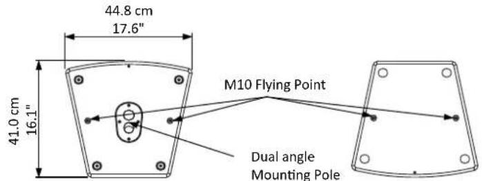
LT15A


natural_image
Line drawing of a white rectangular enclosure with mounting holes and a recessed opening (no text or symbols)
LT215A

natural_image
Technical line drawing of a multi-tiered speaker enclosure with front, top, and side views (no text or symbols)
natural_image
Line drawing of a rectangular industrial enclosure with mounting holes and a side panel (no text or symbols)ACCESSORIES
ACCESSORI
KP210
Adjustable speaker pole for speaker-subwoofer separation, with terminal pieces ∅ 35 mm. Supplied with a bolt locking mechanism incorporating a steel pin for extra safety. Adjustment: 825 - 1320 mm.
FRE300BK
Professional aluminium floor-stand for speaker with terminal pieces ∅ 35mm. Supplied with a screw locking system, a steel safety pin and "Aircushioned" air-damped release device to grant a flexible, fast and easy adjustment. Adjustment: 1470-2180 mm.
KPTLT6
C-shape metal bracket for wall mount of TL6A with +/- 30° free rotati on.
KPTLT8
C-shape metal bracket for wall mount of TL8A with +/- 70° free rotati on.
KPTLT10
C-shape metal bracket for wall mount of TL10A with +/- 70° free rotati on.
KPTLT12
C-shape metal bracket for wall mount of TL12A with +/- 70° free rotati on.
KPTNX04
Horizontal and Verti cal adjustable metal bracket for wall mount, bar length 25 cm, 12.5° 4 step vert. aiming, 10° 7 step hor. aiming, must be used in conjuncti on with KPTLT8 / KPTLT10 / KPTLT12.
PLH300
Single aluminium coupler for 50mm truss with M12 bolt, always use two couplers with the KPTLT8 / KPTLT10 / KPTLT12 for each speaker.
KP210
natural_image
Simple black tripod structure with no text or symbols
natural_image
Technical line drawing of two mechanical bracket components (no text or symbols)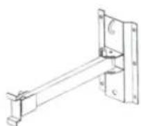
KPTLT6
natural_image
Metal mechanical clamp or bracket component with threaded pins and a central pin (no visible text or symbols)PLH300
CONNECTIONS (FIG.4) CONNESSIONI (FIG.4)


*note: connect both cold and ground to make cable from balanced to unbalanced *nota: connettere insieme cold e ground per cavi da bilanciato a sbilanciato
SAFETY AND PRECAUTIONS
- CAUTION: before using this product read carefully the following safety instructions. Take a look of this manual entirely and preserve it for future reference.
When using any electric product, basic precautions should always be taken, including the following:
- To reduce the risk, close supervision is necessary when the product is used near children.
- Protect the apparatus from atmospheric agents and keep it away from water, rain and high humidity places.
- This product should be site away from heat sources such as radiators, lamps and any other device that generate heat.
- This product should be located so that its location or position does not interfere with its proper ventilation and heating dissipation.
- Care should be taken so that objects and liquids do not go inside the product.
- The product should be connected to a power supply mains line only of the type described on the operating instructions or as marked on the product. Connect the apparatus to a power supply using only power cord included making always sure it is in good conditions.
- ⚠ WARNING: The mains plug is used as disconnect device, the disconnect device shall remain readily operable.
- Do not cancel the safety feature assured by means of a polarized line plug (one blade wider than the other) or with a earth connection.
- Make sure that power supply mains line has a proper earth connection.
- Power supply cord should be unplugged from the outlet during strong thunderstorm or when left unused for a long period of time.
- Do not place objects on the product's power cord or place it in a position where anyone could trip over, walk on or roll anything over it. Do not allow the product to rest on or to be installed over power cords of any type. Improper installations of this type create the possibility of fire hazard and/or personal injury.
- This product may be capable of producing sound levels that could cause permanent hearing loss. Exposure to extremely high noise levels may cause permanent hearing loss. Individuals vary considerably in susceptibility to noise-induced hearing loss, but nearly everyone will lose some hearing if exposed to sufficiently intense noise for a period of time. The U.S. Government's Occupational Safety and Health Administration (OSHA) has specified the permissible noise level exposures shown in the following chart. According to OSHA, any exposure in excess of these permissible limits could result in some hearing loss. To ensure against potentially dangerous exposure to high sound pressure levels, it is recommended that all persons exposed to equipment capable of producing high sound pressure levels use hearing protectors while the equipment is in operation. Ear plugs or protectors in the ear canals or over the ears must be worn when operating the equipment in order to prevent permanent hearing loss if exposure is in excess of the limits set forth here. Keep your's attention that children and pets are more susceptible to excessive noise levels.
| Duration Per Day In Hours | Sound Level dBA Slow Response | Typical Example |
| 8 | 90 | Duo in small club |
| 6 | 92 | |
| 4 | 95 | Subway Train |
| 3 | 97 | |
| 2 | 100 | Very loud classical music |
| 1.5 | 102 | |
| 1 | 105 | Traffic noise |
| 0.5 | 110 | |
| 0.25 or less | 115 | Loudest parts at a rock concert |
IN CASE OF FAULT
- In case of fault or maintenance this product should be inspected only by qualified service personnel when:
- There is a flaw either in the connections or in the supplied connecting cables.
– Liquids have spilled inside the product.
– The product has fallen and been damaged.
– The product does not appear to operate normally or exhibits a marked change in performance. - The product has been lost liquids or gases or the enclosure is damaged.
- Do not operate on the product, it has no user-serviceable parts inside, refer servicing to an authorized maintenance centre.
TROUBLESHOOTING
| No Power | The loudspeaker's "POWER" switch is off.Make sure the mains AC outlet is live (check with a tester or a lamp).Make sure the mains plug is securely plugged into mains AC outlet. |
| No Sound • Is the input | LEVEL control for the channel turned up?Is the SIGNAL LED illuminated? If not check if your signal level is too low or check the signal cable, mixer and other equipment setting and cabling.Are you sure your signal cables works properly? check it using a cable tester or replacing with a new one.Is the SPEAKON cable connector correctly inserted? turn it clockwise until it clicks.Are you sure your power cable works properly? check it using a cable tester or replacing with a new one. |
| Distorted Sound • Input | signal level is too high. Turn down your level controls.NOTE: The loudspeakers should never be operated at a level which causes the amplifier Clip LEDs to illuminate constantly. |
| Different channel level | Check if are using a balanced cable for one channel and an unbalanced one for the other, as this would cause a considerable difference in channel levels.Be sure that your loudspeaker system is fully connected and both loudspeakers have the same impedance. |
| Noise / Hum | Enable GND LIFT button on rear panel, if the problem persist press all GND LIFT buttons for all system's amplifiers.Whenever possible, preferably use only balanced cables. Unbalanced lines may also be used but may result in noise over long cable runs.Sometimes it helps to plug all audio equipment into the same AC circuit so they share a common ground. |
CE CONFORMITY
• Proel products comply with directive 2004/108/EC (EMC), as stated in EN 55103-1 and EN 55103-2 standards and with directive 2006/95/CE (LVD), as stated in EN 60065 standard.
• Under the EM disturbance, the ratio of signal-noise will be changed above 10dB.
PACKAGING, SHIPPING AND COMPLAINT
- This unit package has been submitted to ISTA 1A integrity tests. We suggest you control the unit conditions immediately after unpacking it.
- If any damage is found, immediately advise the dealer. Keep all unit packaging parts to allow inspection.
- Proel is not responsible for any damage that occurs during shipment.
- Products are sold "delivered ex warehouse" and shipment is at charge and risk of the buyer.
- Possible damages to unit should be immediately notified to forwarder. Each complaint for package tampered with should be done within eight days from product receipt.
WARRANTY AND PRODUCTS RETURN
• Proel products have operating warranty and comply their specifications, as stated by manufacturer.
- Proel warrants all materials, workmanship and proper operation of this product for a period of two years from the original date of purchase. If any defects are found in the materials or workmanship or if the product fails to function properly during the applicable warranty period, the owner should inform about these defects the dealer or the distributor, providing receipt or invoice of date of purchase and defect detailed description. This warranty does not extend to damage resulting from improper installation, misuse, neglect or abuse. Proel S.p.A. will verify damage on returned units, and when the unit has been properly used and warranty is still valid, then the unit will be replaced or repaired. Proel S.p.A. is not responsible for any "direct damage" or "indirect damage" caused by product defectiveness.
INSTALLATION AND DISCLAIMER
- Proel products have been expressly designed for audio application, with signals in audio range (20Hz to 20kHz). Proel has no liability for damages caused in case of lack of maintenance, modifications, improper use or improper installation non-applying safety instructions.
- The installation of these speakers is provided for indoors, in case of use outdoors be sure that the speakers are installed correctly in a safe location protected from wind, rain and humidity. To avoid performance deterioration of mechanical, acoustics and electrical parts is not advisable to leave these speakers exposed outdoors for a long period of time, so we suggest a temporary installation for the limited sound events.
- The installation of these speakers is provided for floor or by means of specific stands able to support their weight. Therefore avoid installation on unstable elements such as: furniture, chairs and vibrant surfaces as stages or other speakers without appropriate fix point specifically designed to avoid speaker movement. Then avoid the use of inadequate supports, we suggest to use PROEL stands and accessories only.
- In case of the speakers are provided of rigging points: DO NOT SUSPEND THE SPEAKERS FROM THE HANDLES, use exclusively these rigging points. Consult professional rigger or structural engineers prior to suspending loudspeakers from a structure not intended for that use. Always know the working load limit of the structure supporting the loudspeakers. Always make sure that the rigging hardware minimum rating is at least five times the actual load, speakers and rigging hardware.
- In case of suspended installations of active loudspeakers where is not possible to turn on and off the speakers from their appropriate switches, we recommend to install switches on the mains lines, for this purpose consult an expert electrician for the exact dimension of wiring.
- Locate the speakers as far away as possible from radio or television receivers or other sensitive equipment. These speakers have a strong magnetic field which can induce hum and noise into unshielded devices that are located nearby with consequent deterioration of reception of image and sound.
- Proel S.p.A. reserves the right to change these specifications at any time without notice.
- Proel S.p.A. declines any liability for damages to objects or persons caused by lacks of maintenance, improper use, installation not performed with safety precautions and at the state of the art.
POWER SUPPLY AND MAINTENANCE
- Clean only with dry cloth.
- Check periodically that the slots for its proper ventilation and heating dissipation are not obstructed by dust, remove the dust using a dry brush or a compressed air gun.
- The amplified loudspeakers of Proel have been designed with CLASS I construction and must be connected always to a mains socket outlet with a protective earth connection (the third grounding prong).
- Before connecting the product to the mains outlet make certain that the mains line voltage matches that shown on the rear of the product, a tolerance of up to ± 10% is acceptable.
- Inside the amplified loudspeakers are present special safety devices such as:
√ Transformer and amplifier over-heating protection.
√ Protection against excessive power applied at each speaker.
- △ THE REPLACEMENT OF FUSES INSIDE THE APPARATUS MUST BE MADE ONLY BY QUALIFIED PERSONNEL.
- CHECK THE CONDITION OF THE PROTECTION FUSE, ACCESSIBLE OUTWARD, ONLY WITH THE APPARATUS SWITCHED OFF AND DISCONNECTED FROM THE MAINS LINE OUTLET.
- REPLACE THE PROTECTION FUSE ONLY WITH SAME TYPE AS SHOWN ON THE PRODUCT.
- IF AFTER THE SUBSTITUTION, THE FUSE INTERRUPTS AGAIN THE APPARATUS WORKING, DO NOT TRY AGAIN THEN CONTACT THE PROEL SERVICE CENTRE.
GENERAL INFORMATION
Thank you for having chosen a PROEL product.
The LITE Series by PROEL is an extended range of active and passive speaker systems with plywood cabinet offering the renowned PROEL sound and a high-level performance in a reliable and affordable package. For the construction of the cabinets we have used plywood, a very lightweight and durable material that makes moving and installing these speakers very quick and easy. Strong, anti-scratch paint and steel grilles with an internal foam layer provide proper protection for years of service. The dual-angle pole holder featured in LT8, LT10, LT12 and LT15 models offers the possibility to obtain a more uniform coverage of the audience.
For the high frequency reproduction of LITE Series we have designed wide-dispersion horns, able to provide constant coverage for large audiences and detailed response with low distortion. The high-excursion woofers, together with carefully tuned vented cabinets, offers an extended response with deep and tight basses.
The LITE Series includes 6 active models ranging from 6.5" to dual 15" woofers, plus 1 satellites + subwoofer system. The extremely lightweight power modules used in the active models feature the latest technologies for amplification, such as Switch Mode Power Supply and CLASS D output stages, which provides a massive amount of power with a reduced weight. The power modules are hosted in fully-sealed die-cast aluminium boxes that provides protection, perfect insulation of the cabinet from the outside and extremely efficient cooling. Each module includes a sophisticated pre-amp section with up to 24 dB/oct. phase aligned crossover filters and active EQ filters for the system's fine tuning. The DUAL LIMITER circuit ensures an undistorted sound even at the loudest level and a total loudspeaker protection.
The LT loudspeaker systems can be combined with the SW subwoofers: available in 5 models and capable of providing the perfect low frequency extension for each model of the series.
INSTRUCTIONS (FIG. 1 / 2 / 3 / 4 / 5)
1. INPUT (combo XLR-JACK input)
This is a female combo connector, which accepts a XLR or a JACK plug from almost any type of equipment with a balanced or unbalanced outputs. The XLR input is wired as follows:
Pin 1 = shield or ground
Pin 2 = + positive or "hot"
Pin 3 = - negative or "cold"
The JACK input is wired as follows:
Tip = + positive or "hot"
Ring = - negative or "cold"
Sleeve = shield or ground
When connecting an unbalanced signal (RCA pin jack inputs on LT6A model), wire them as follows:
Pin2 / Tip = + positive or "hot"
Pin 1-3 / Sleeve = shield or ground
NOTE: whenever possible, use always balanced cables. Unbalanced lines may also be used but may result in noise over long cable runs. In any case, avoid using a balanced cable for one channel and an unbalanced one for the other.
2. LINK (XLR output)
This is a male XLR connector, it is connected in parallel with the respective INPUT socket, so the LINK is wired as INPUT. Connect these to the inputs of other powered speakers to make an array.
3. MIC / LINE switch
This switch adjusts the gain of the LINE/MIC input varying the sensitivity between MIC, suited to connect a microphone, and LINE, suited to connect a device with high level output like a MIXER, a CD player etc.
NOTE: do not use the MIC sensitivity to "pump up" the volume with the LINE level equipment, in order to avoid the analog input saturation that could produce very annoying distortion.
4. GND LIFT switch
This switch lift the ground of the balanced audio inputs from the earth-ground of the amplifier. If you have HUM noise problem on one or more loudspeaker try to change the position of these switches (often all up or all down for all the amplifiers in the system). Please note that to have an effect all cables must be balanced.
5. LEVEL control
Rotary level control: it attenuates the level of the signal sent to the INPUT. The attenuation ranges from "0" fully closed (the signal is completely attenuated) to "10" fully open, nominal level (the signal is not attenuated in any way, so it is fed to the internal amplifier at the same level at which it arrives on input).
6. LOW control
This control gives you up to 6 dB boost or cut at 90 Hz with a "SHELVING" curve shape. Use it to add or reduce the sound "punch", or to reduce the low frequency rise when the speaker is set near walls or on floor as stage monitor (not available on LT6A model).
7. HIGH control
This control gives you up to 6 dB boost or cut at 8 KHz with a "SHELVING" curve shape. Use it to add or reduce the sound "clarity" and "brightness" (not available on LT6A model).
8. SIGN/LIMIT indicator
GREEN LED illuminates to indicate the presence of the signal at the amplifier input.
RED LED illuminates when the internal amplifier's output is limited. When this LED flashes reduce the input signal level.
9. ON indicator
GREEN LED: when lighted indicates amplifier has been turned on and AC power is available.
10. POWER switch
Speaker is "ON" when the switch is in the "I" position, use this switch to set the speaker power to ON or OFF.
NOTE: When you shut down your equipment, turn off the speaker first. When powering up, turn on the speaker last.
11. LINE VOLTAGE selector
This switch sets the AC voltage line of your country (usually it is set by factory and isn't necessary to change it). The 115V setting is for mains line in the range of 105-120V\~ and 230V setting is for mains line in the range of 210-240V\~.

WARNING: AN INCORRECT SETTING OF AC LINE VOLTAGE COULD DAMAGE SERIOUSLY THE INTERNAL ELECTRONICS!
12. FUSE holder
Here is placed the mains protecti on fuse.

WARNING: REPLACE THE PROTECTION FUSE ONLY WITH SAME TYPE AS SHOWN ON THE PRODUCT. IF AFTER THE SUBSTITUTION, THE FUSE INTERRUPTS AGAIN THE APPARATUS WORKING, DO NOT TRY AGAIN THEN CONTACT THE PROEL SERVICE CENTER.
13. AC\~ socket
Here's where you plug in your speaker's mains supply cord. You should always use the mains cord supplied with the speaker. Be sure your speaker is turned off before you plug the mains supply cord into an electrical outlet.
AVVERTENZE PER LA SICUREZZA



- FCC COMPLIANCE NOTICE
- INDICE
- FREQUENCY RESPONSE RISPOSTA IN FREQUENZA
- ACCESSORIES
- ACCESSORI
- KP210
- FRE300BK
- KPTLT6
- KPTLT8
- KPTLT10
- KPTLT12
- KPTNX04
- PLH300
- SAFETY AND PRECAUTIONS
- IN CASE OF FAULT
- CE CONFORMITY
- PACKAGING, SHIPPING AND COMPLAINT
- WARRANTY AND PRODUCTS RETURN
- INSTALLATION AND DISCLAIMER
- POWER SUPPLY AND MAINTENANCE
- GENERAL INFORMATION
- INSTRUCTIONS (FIG. 1 / 2 / 3 / 4 / 5)
- INPUT (combo XLR-JACK input)
- LINK (XLR output)
- MIC / LINE switch
- GND LIFT switch
- LEVEL control
- LOW control
- HIGH control
- SIGN/LIMIT indicator
- ON indicator
- POWER switch
- LINE VOLTAGE selector
- FUSE holder
- AC\~ socket
- AVVERTENZE PER LA SICUREZZA
Brand : Proel
Model : LT10A
Category : Loudspeaker