
Flash 5A V2 - Loudspeaker Proel - Free user manual and instructions
Find the device manual for free Flash 5A V2 Proel in PDF.


| Product Type | Active PA Speaker |
| Model | Flash 5A V2 |
| Brand | Proel |
| Dimensions (W x H x D) | Approx. 280 x 430 x 250 mm |
| Weight | Approx. 8.5 kg |
| Power Supply | AC 100-240V, 50/60Hz |
| Amplifier Power | 200W RMS |
| Frequency Response | 60 Hz - 20 kHz |
| Speaker Configuration | 5" Woofer + 1" Tweeter |
| Inputs | XLR/Jack Combo, RCA |
| Outputs | XLR Link Out |
| Controls | Volume, EQ, Power Switch |
| Enclosure Material | Polypropylene |
| Mounting | Pole mount socket (36mm) |
| Protection Features | Overload, Thermal, Limiter |
| Cleaning Instructions | Wipe with dry cloth; avoid liquids |
| Safety | Do not expose to rain or moisture |
| Spare Parts & Repair | Contact authorized Proel service center |
| General Information | Designed for portable PA applications |
Frequently Asked Questions - Flash 5A V2 Proel
User questions about Flash 5A V2 Proel
0 question about this device. Answer the ones you know or ask your own.
Ask a new question about this device
Download the instructions for your Loudspeaker in PDF format for free! Find your manual Flash 5A V2 - Proel and take your electronic device back in hand. On this page are published all the documents necessary for the use of your device. Flash 5A V2 by Proel.
USER MANUAL Flash 5A V2 Proel
R&D Department Testing Procedure
From PROEL R&D DEPT.
To PROEL SERVICE DEPT.
Object FLASH5A amplifier module - TESTING PROCEDURE
Date 30/04/2014
Instruments required:
1) Sinusoidal audio signal generator
2) 100MHz or more dual trace oscilloscope (scope)
3) True RMS digital multimeter (DMM) with dBu scale
4) 250W or more Variac transformer with 0-250 Vac range (230V european version) or with 0-140 Vac range (120V US version)
5) 4 Ω 100W or more resistive load
6) 8 Ω 50W or more resistive load
7) Music and pink noise signal generator (CD player)

IMPORTANT: The oscilloscope must be insulated from the earth ground.
1. Set up
- Check the correct earth main connection on the rear surface of the front panel.
- Check the insulation between the heat sink and the case of IC4, IC5 and IC3.
- Set the LINE LEVEL control full clockwise.
- Set the NEARFIELD/MIDFIELD button in NEARFIELD position.
- Switch OFF the amplifier module.
2. Low amplifier check
- Connect the mains of amplifier module to VARIAC and set it at zero AC voltage.
- Connect the scope CH1 GND clip to P8 black wire/faston (GND), scope CH1 probe tip to P6 red wire/faston (LOW OUT) and scope CH2 probe tip to P10 black wire/faston (HIGH OUT).
- Switch ON the amplifier module.
- Increase slowly the VARIAC voltage up to the nominal value (230Vac or 120Vac).
- Check the transformer secondary voltages with DMM (without signal on input):
52 ±2 Vac between red wire
32 ±2 Vac between yellow wire
- Using DMM check also the +15Vdc / -15Vdc supplies on relative voltage regulator outputs (IC4 & IC5 devices).
- Connect the signal generator to LINE INPUT (XLR/JACK socket) and set it at 100 Hz, -10 dBu.
- Verify that CH1 (LOW OUT) signal is 30V ±6 Vpp.
- Check of SIGNAL/LIMIT LED function, moving the volume potentiometer of the amplifier; when the output signal is < 2 Vpp the led must be OFF when the output signal is > 2 Vpp, the led must be GREEN.
- Rotate the volume potentiometer knob fully clockwise.
- Set the signal generator at 0 dBu.
-
Connect the 4 Ω load resistor at LOW OUT and verify that the signal is symmetrical refer to GND, without detectable distortion and oscillation.
-
Remove signal from XLR Input.
- Connect the signal generator to LINE INPUT (RCA socket) and set it at -20 dBu.
- Verify that low amplifier output signal is 28V ±6 Vpp.
NOTE: the low amplifier is designed with a class-D half-bridge self-oscillating amplifier around the IRS2092 ic, to see in detail how this amplifier works consult IRS2092 data sheet and related application notes available on International Rectifier website (www.irf.com). The low amplifier oscillating frequency is in the range of 400-420 KHz. If there is a problem in the nested loop the amplifier doesn't oscillate: switch off then check TR6. If the mosfets isn't fault check the voltage, using the DMM, between -VCC and pin 3 of IC2 (7812), this is the voltage regulator of low side mosfet driver, if this regulator doesn't work the amplifier doesn't oscillate.
3. COMPRESSOR check of LOW amplifier
- Increase the signal at +10 dBu and check that the output signal remains constant at 40 ±4 Vpp. Check that the SIGNAL/COMP LED has changed the colour from GREEN to RED.
- Disconnect the 4ohm □load resistor from the LOW amplifier output.
6. HIGH amplifier check
- Connect the signal generator to LINE INPUT (XLR/JACK socket) and set it at 10 KHz, 0 dBu.
- Verify that the CH2 (HIGH OUT) signal is symmetrical referring to GND, without detectable distortion and oscillation.
- Connect the 8 Ω load resistor at LOW OUT and check that the HIGH amplifier output signal is limited to 20 ±3 Vpp.
7. X-OVER check.
- Disconnect all resistive loads and set the signal generator to -10 dBu.
- Sweep the frequency and check that the LOW amplifier power out signal level is as the 1a plot and HIGH frequency amplifier power signal level is as 1b plot.

line
| Frequency (Hz) | Curve 1a | Curve 1b | | -------------- | -------- | -------- | | 20 | -10 | - | | 50 | - | - | | 100 | -23 | - | | 200 | - | - | | 500 | - | - | | 1k | - | - | | 2k | - | - | | 5k | - | - | | 10k | - | - | | 20k | - | -10 |- Set the NEARFIELD/MIDFIELD button in MIDFIELD position.
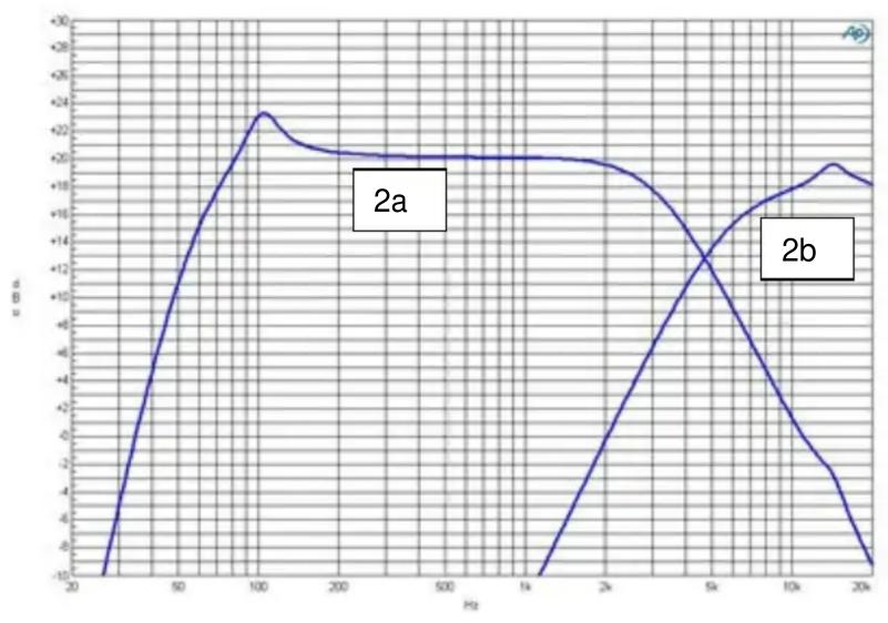
- Sweep again the frequency and check that the LOW amplifier power out signal level is as the 2a plot and HIGH frequency amplifier power signal level is as 2b plot.
line
| Hz | Value | | ---- | ----- | | 20 | -10 | | 50 | 10 | | 100 | 2.3 | | 200 | 2.0 | | 500 | 2.0 | | 1k | 2.0 | | 2k | 1.5 | | 5k | 1.0 | | 10k | 0.5 | | 20k | -1.0 |8: Burn in
- Connect to the LINE input of the amplifier module the 3:1 pink noise source.
- Connect a 4 Ω 100W resistive load to the LOW amplifier output.
- Connect a 8 Ω 50W resistive load to the HIGH amplifier output.
- Switch ON the amplifier module.
- Increase the pink noise level until the SIGNAL/LIMIT LED is flickering in RED/GREEN light.
- Hold the amplifier in vertical position and run the burn-in test for 2 hours min.
9: Final acoustic check
- After the burn-in test, the amplifier module must still work properly. An acoustic or electric test (with speaker box and audio signal) is needed to verify this condition.



Brand : Proel
Model : Flash 5A V2
Category : Loudspeaker